
Study on the Dip Angle Effect of Asymmetric Deformation and Failure of the Gob-Side Coal–Rock Roadway in Gently Inclined Coal Seam

 ,
,  ,
,  and
and
Abstract
:1. Introduction
2. Asymmetric Deformation Characteristics of Surrounding Rock in the Gob-Side Coal–Rock Roadway
- (1)
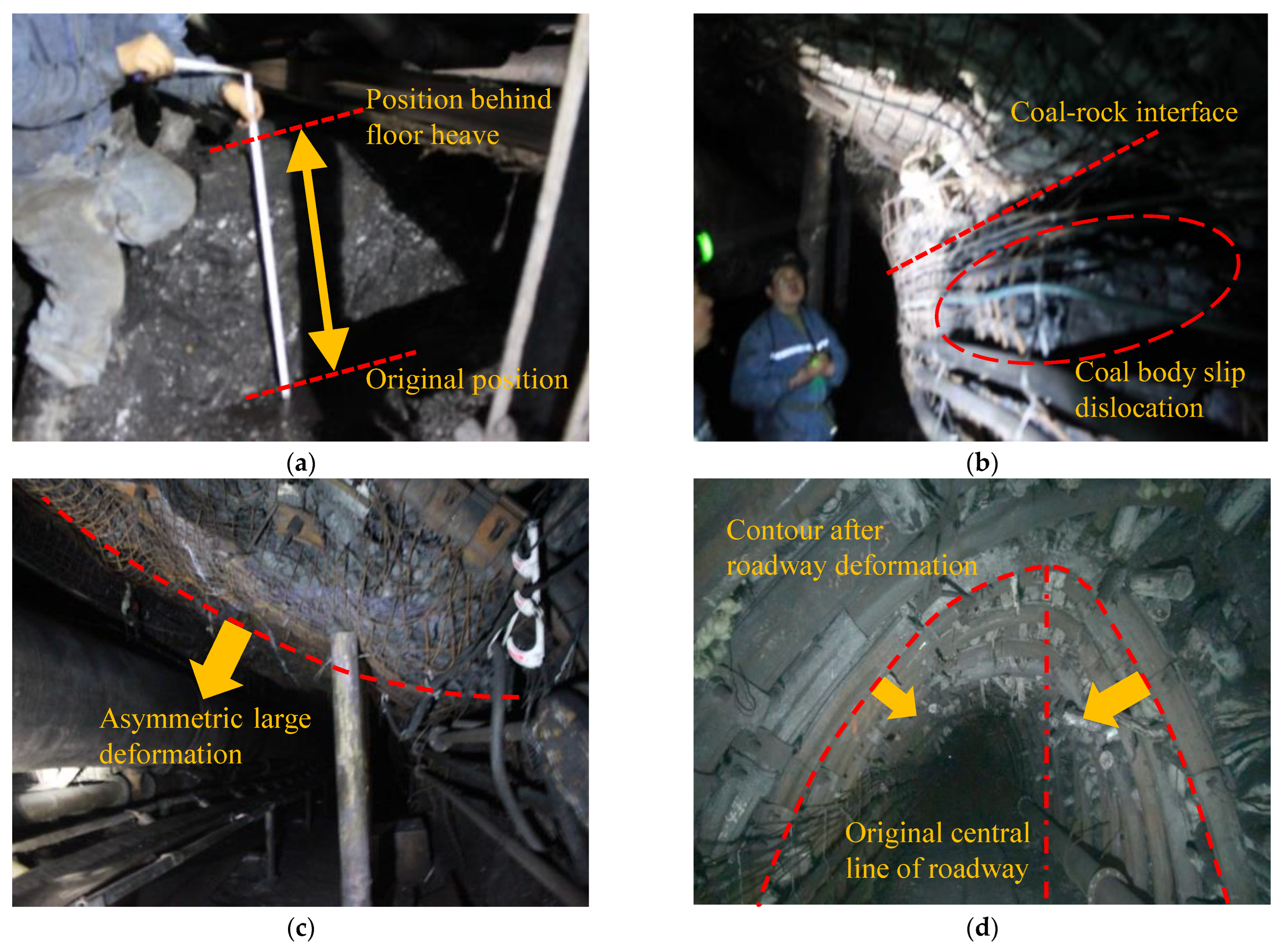
- Continuous floor heave. Due to the infiltration of fissure water in the surrounding rock and the influx of water from the neighboring mining, the floor was seriously flooded after roof watering, and floor heave deformation was continuously produced, as shown in Figure 1a.
- (2)
- Coal–rock interface slip dislocation. The coal–rock body at the coal–rock interface on the side of the roadway, especially at the side of the narrow coal pillar, produced an obvious slip dislocation deformation along the coal–rock interface. When it was serious, it presented the phenomenon of stepped bulging, as shown in Figure 1b.
- (3)
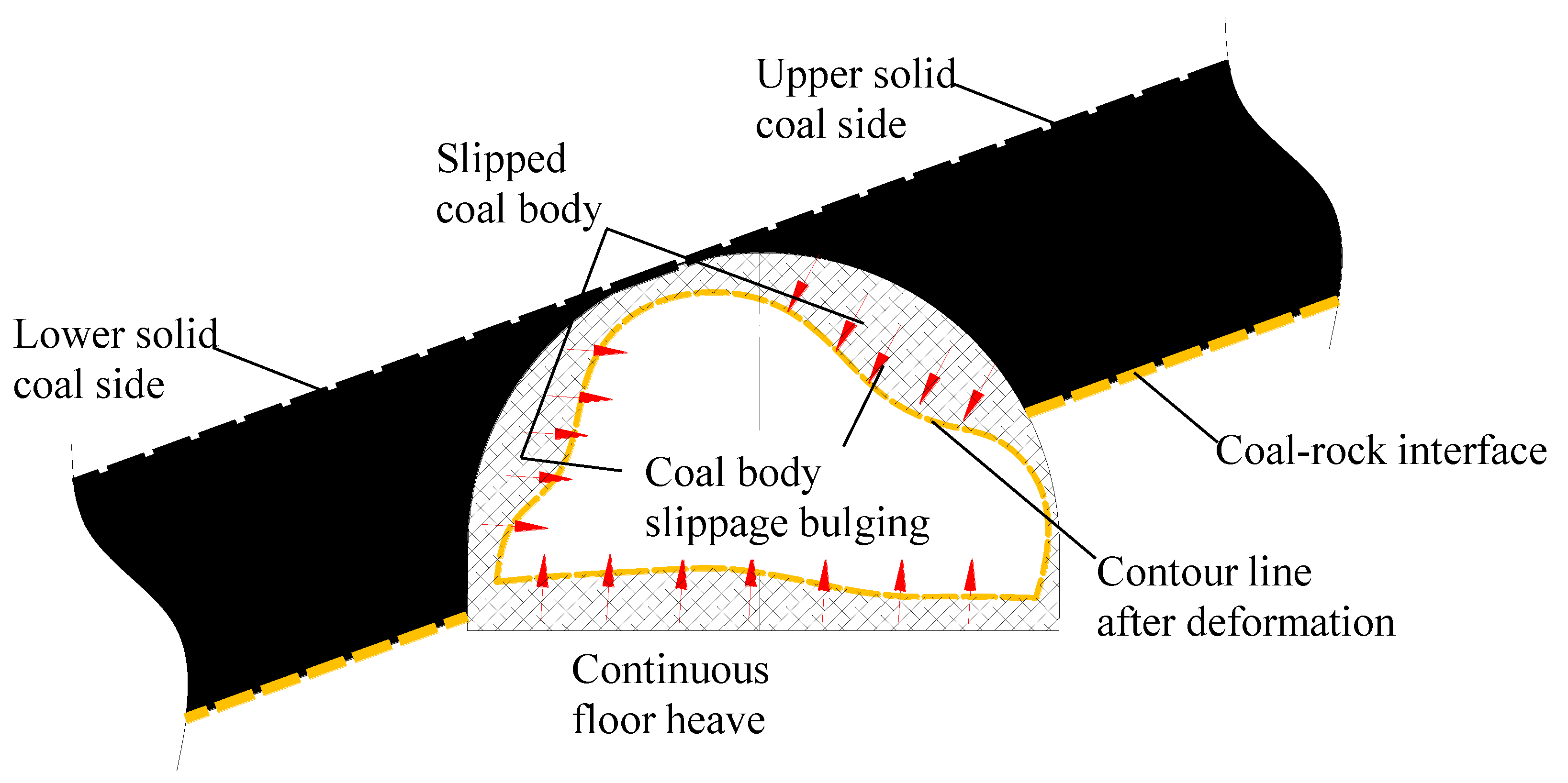
- The two sides showed asymmetric deformation characteristics. It was found in the investigation that, under the existing support model, the deformation of the coal pillar side of the roadway was generally greater than that of the solid coal side, as shown in Figure 1c,d. According to the results of the field investigation, the sketch of asymmetric deformation characteristics of the roadway was drawn in Figure 2.
3. Engineering Geology Overview
4. Asymmetric Deformation Mechanism of Coal–Rock Interface Slip Dislocation under the Influence of Dip Angle
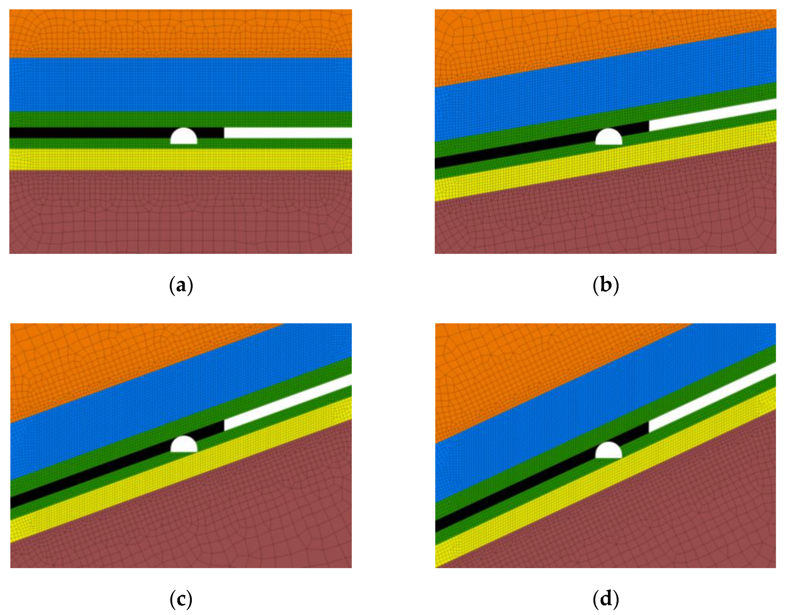
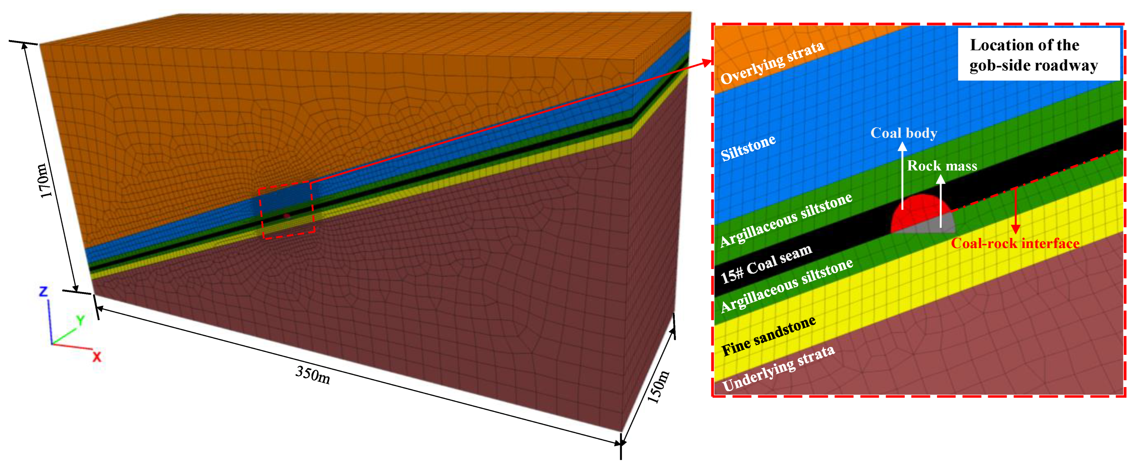
5. Numerical Simulation of Asymmetric Deformation and Failure Characteristics of the GCRGICS under Different Dip Angles
5.1. Establishment of Numerical Calculation Mode
5.2. Numerical Simulation Results
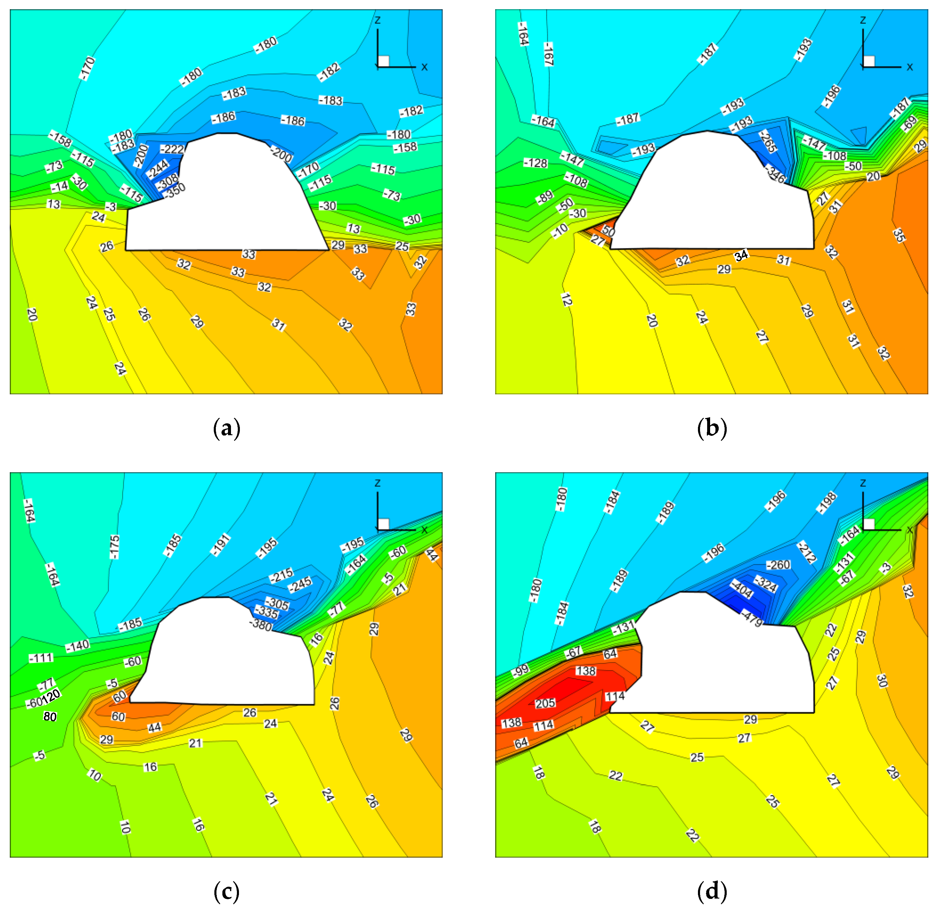
5.2.1. Asymmetric Deformation Characteristics of the Gob-Side Coal–Rock Roadway under Different Dip Angles
- (1)
- Vertical displacement
- (2)
- Horizontal displacement
- (3)
- Asymmetric deformation rate
- (4)
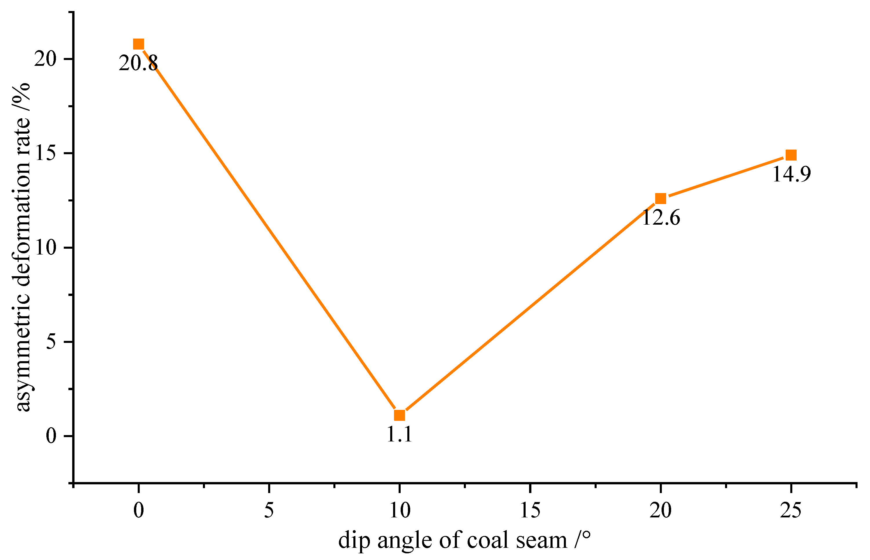
- Evolution law of asymmetric deformation rate
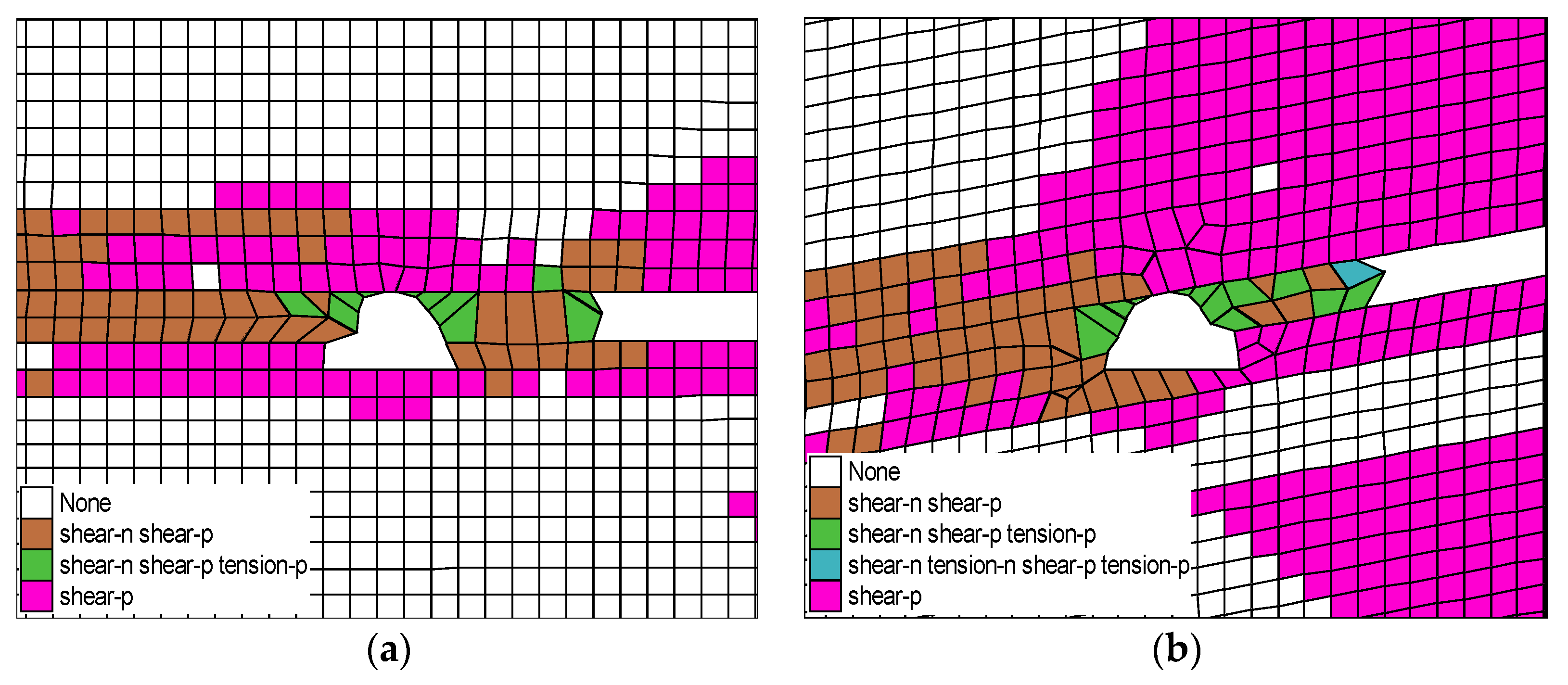
5.2.2. Asymmetric Failure Characteristics of the Gob-Side Coal–Rock Roadway under Different Dip Angles
6. Conclusions
- (1)
- This study found the influence law of the dip angles on the asymmetric deformation and failure of the surrounding rock of the gob-side coal–rock roadway. With the increase of the dip angle, the shear–slip dislocation deformation of the coal–rock interface intensified. The deformation of the upper coal body slippage and misalignment was increased, the narrow coal pillar yielded instability gradually, and the surrounding rock stress transferred to the lower solid coal side. The maximum slip deformation area gradually transferred from the upper arc triangle coal to the lower arc triangle coal, and the asymmetric deformation characteristics of the surrounding rock were more obvious.
- (2)
- For the GCRGICS, the relationship between asymmetric deformation rate and coal seam dip angle was roughly V-shaped. When the coal seam dip angle was 10°, the asymmetric deformation rate was the smallest, only 1.1%. When the coal seam dip angles were 0°, 20° and 25°, due to the difference of slip dislocation deformation between the solid coal side and the upper goaf side, the asymmetric deformation rates were relatively large, 20.8%, 12.6% and 14.9%, respectively.
- (3)
- The plastic zone range of the surrounding rock expanded with the increase of the dip angle, it showed that the failure range of the surrounding rock of the gob-side roadway increased significantly after the increase of the dip angle. The new expansion range was mainly located in the roof area, and the plastic zone of the floor was mainly concentrated on the side of solid coal and developed from symmetric distribution to asymmetric distribution with the increase of dip angle.
- (4)
- Compared with the existing research on the coal–rock roadways, the significance of this study was to provide a scientific basis and theoretical guidance for the formulation of the surrounding rock control scheme of the gob-side coal–rock roadway under different dip angles. For the asymmetric deformation roadways under different dip angles, the asymmetric support designs should be carried out according to the load distribution law of the surrounding rock, such as anchor cable reinforcement support or adjustment of bolt (cable) support parameters for differential support countermeasures, so as to realize the strength coupling between the support body and the surrounding rock and make the surrounding rock and the support body uniformly and harmoniously deform within the allowable range of engineering application.
Author Contributions
Funding
Institutional Review Board Statement
Informed Consent Statement
Data Availability Statement
Conflicts of Interest
References
- Gao, L.; Wang, J.C.; Kong, D.Z.; Wu, G.Y.; Ma, Z.Q. Deformation mechanism and repairing technology for coal-rock uphill roadway under influence of dynamic pressure. China Saf. Sci. J. 2020, 30, 67–73. [Google Scholar]
- Yu, W.J.; Feng, T.; Wang, W.J.; Wang, P.; Yuan, C.; Guo, G.Y.; Du, S.H. Support problems and solutions of roadway surrounding rock for thin coal seams under complex conditions in Southern China. J. China Coal Soc. 2015, 40, 2370–2379. [Google Scholar]
- Gao, L.; Zhao, S.H.; Huang, X.F.; Ma, Z.Q.; Kong, D.Z.; Kang, X.T.; Han, S. Experimental study on surrounding rock characteristics of gateway in Panjiang mining area. J. GZU (Nat. Sci.) 2022. Available online: http://kns.cnki.net/kcms/detail/52.5002.N.20220412.0956.002.html (accessed on 13 April 2022).
- Zhang, P.D.; Gao, L.; Liu, P.Z.; Wang, Y.Y.; Liu, P.; Kang, X.T. Study on the influence of borehole water content on bolt anchoring force in soft surrounding rock. Shock Vib. 2022, 2022, 2384626. [Google Scholar] [CrossRef]
- Yu, W.J.; Feng, T.; Wang, W.J.; Liu, H.; Ma, P.Y.; Wang, P.; Li, R.H. Deformation mechanism, control principle and technology of soft half coal rock roadway. Chin. J. Rock Mech. Eng. 2014, 33, 658–671. [Google Scholar]
- Majdi, A.; Rezaei, M. Prediction of unconfined compressive strength of rock surrounding a roadway using artificial neural network. Neural Comput. Appl. 2013, 23, 381–389. [Google Scholar] [CrossRef]
- Jin, G.; Wang, L.G.; Li, Z.L.; Zhang, J.H. Study on the gateway rock failure mechanism and supporting practice of half-coal-rock extraction roadway in deep coal mine. J. Min. Saf. Eng. 2015, 32, 963–967. [Google Scholar]
- Wang, M.; Xiao, T.Q.; Gao, J.; Liu, J.L. Deformation mechanism and control technology for semi coal and rock roadway with structural plane under shearing force. J. Min. Saf. Eng. 2017, 34, 527–534. [Google Scholar]
- Liu, C.X. Research of imitating the numerical calculation on rock structure stability of half coal seam roadway. J. Basic Sci. Eng. 2000, 8, 16–21. [Google Scholar]
- Yao, Q.; Feng, T.; Wang, W.J.; Yu, W.J.; Wang, P.; Yuan, C. Study on deformation and failure mechanism and support control measure of half coal rock roadway under extremely fractured surrounding rock. J. Saf. Sci. Technol. 2015, 11, 32–39. [Google Scholar]
- Zhang, H.L.; Wang, L.G.; Tu, M. Failure evolution laws and control technology of roadway surrounding rock. J. Heilongjiang Inst. Sci. Technol. 2013, 23, 258–262. [Google Scholar]
- Jin, G.; Hao, G.S. Numerical simulation of anchored rope supporting in half-coal and half-rock roadway. Coal Min. Technol. 2012, 17, 55–58. [Google Scholar]
- Luo, J.A.; Wang, L.G.; Hou, H.Q. Preliminary research on coal-rock structural plane of mining roadway located in thin coal seam. Min. Res. Dev. 2014, 34, 22–26. [Google Scholar]
- Wang, H.; Jiang, C.; Zheng, P.Q.; Zhao, W.J.; Li, N. A combined supporting system based on filled-wall method for semi coal-rock roadways with large deformations. Tunn. Undergr. Space Technol. 2020, 99, 103382. [Google Scholar] [CrossRef]
- Sun, Y.N.; Zhou, H.C.; Zhou, J.R.; Xiong, Z.Q. Control technique of floor heave in semi coal and rock roadway with weak floor. J. Min. Saf. Eng. 2007, 24, 340–344. [Google Scholar]
- Yu, W.J.; Wu, G.S.; Liu, H.; Wang, P.; An, B.F.; Liu, Z.; Huang, Z.; Liu, F.F. Deformation characteristics and stability control of soft coal-rock mining roadway in thin coal seam. J. China Coal Soc. 2018, 43, 2668–2678. [Google Scholar]
- Xu, T.B. Surrounding rock control technique in semi-coal and semi-rock roadway with ultra long distance. J. Min. Saf. Eng. 2009, 26, 168–172. [Google Scholar]
- Gao, L.; Liu, P.Z.; Zhang, P.D.; Wu, G.Y.; Kang, X.T. Influence of fracture types of main ro-of on the stability of surrounding rock of the gob-side coal-rock roadway in inclined coal seams and its engineering application. Goal Geol. Explor. 2022. Available online: https://kns.cnki.net/kcms/detail/61.1155.p.20220416.0838.002.html (accessed on 20 April 2022).
- Zhang, N.; Li, B.Y.; Li, G.C.; Qian, D.Y.; Yu, X.Y. Inhomogeneous damage and sealing support of roadways through thin bedded coal-rock crossovers. J. Min. Saf. Eng. 2013, 30, 1–6. [Google Scholar]
- Yang, X.P.; Xie, X.P.; Liu, X.N. Comprehensive control technology of floor heave in soft floor roadway of semi coal rock. Saf. Coal Mines 2013, 44, 78–81. [Google Scholar]
- He, X.K.; Wei, S.J.; Gao, J.H. Numerical simulation optimization on parameters of bolt support in semi coal and rock roadways. J. HPU (Nat. Sci.) 2009, 28, 705–708. [Google Scholar]
- Li, J.F.; Guo, W.Y.; Zhang, C.L.; Cheng, C.X.; Liu, J.K.; Zhou, G.L. Supporting Technology of fully mechanized half-coal rock mining roadway in thin seam. Saf. Coal Mines 2013, 44, 97–99, 103. [Google Scholar]
- Zheng, Y.; He, C.C.; Xi, C.D.; Yao, B.; Liu, B.H. Analysis on numerical simulation of anchor setting parameters in the semi-coal and semi-rock roadway. Coal Chem. Ind. 2015, 38, 90–92. [Google Scholar]
- Cui, Q.L.; Wu, J.X. Parameters optimization of bolting in mining coal-rock roadway under shallow overburden. Coal Eng. 2015, 47, 48–50. [Google Scholar]
- Rezaei, M.; Hossaini, M.F.; Majdi, A. Determination of longwall mining-induced stress using the strain energy method. Rock Mech. Rock Eng. 2015, 48, 2421–2433. [Google Scholar] [CrossRef]
- Rezaei, M.; Hossaini, M.F.; Majdi, A. Development of a time-dependent energy model to calculate the mining-induced stress over gates and pillars. J. Rock Mech. Geotech. Eng. 2015, 12, 306–317. [Google Scholar] [CrossRef]
- Das, A.J.; Mandal, P.K.; Paul, P.S.; Sinha, R.K. Generalised analytical models for the strength of the inclined as well as the flat coal pillars using rock mass failure criterion. Rock Mech. Rock Eng. 2019, 52, 3921–3946. [Google Scholar] [CrossRef]
- Barton, N. Review of a new shear-strength criterion for rock joints. Eng. Geol. 1973, 7, 287–332. [Google Scholar] [CrossRef]
- Bandis, S.C.; Lumsden, A.C.; Barton, N.R. Fundamentals of rock joint deformation. Int. J. Rock Mech. Min. Sci. 1983, 20, 249–268. [Google Scholar] [CrossRef]
- Rezaei, M.; Hossaini, M.F.; Majdi, A. A time-independent energy model to determine the height of destressed zone above the mined panel in longwall coal mining. Tunn. Undergr. Space Technol. 2015, 47, 81–92. [Google Scholar] [CrossRef]
- Gao, L. Asymmetric Deformation Characteristics and Failure Mechanism of the Gob-Side Coal-Rock Roadway and Its Control Techniques in Gently Inclined Coal Seam. Ph.D. Thesis, China University of Mining and Technology, Beijing, China, 2020. [Google Scholar]


| Lithology | Density (g/cm3) | Bulk (GPa) | Shear (GPa) | Cohesion (MPa) | Friction (°) |
|---|---|---|---|---|---|
| Overlying strata | 2.500 | 12.00 | 7.60 | 2.30 | 28 |
| Siltstone | 2.325 | 10.85 | 7.00 | 7.90 | 31 |
| Argillaceous siltstone | 2.370 | 11.90 | 7.80 | 8.60 | 33 |
| No. 15 coal seam | 1.395 | 0.75 | 0.23 | 0.21 | 13 |
| Fine sandstone | 2.325 | 10.85 | 7.00 | 7.90 | 31 |
| Underlying strata | 2.500 | 12.00 | 7.60 | 2.30 | 28 |
Publisher’s Note: MDPI stays neutral with regard to jurisdictional claims in published maps and institutional affiliations. |
© 2022 by the authors. Licensee MDPI, Basel, Switzerland. This article is an open access article distributed under the terms and conditions of the Creative Commons Attribution (CC BY) license (https://creativecommons.org/licenses/by/4.0/).
Share and Cite
Gao, L.; Zhan, X.; Zhang, P.; Wen, Z.; Ma, Z.; Kong, D.; Kang, X.; Han, S. Study on the Dip Angle Effect of Asymmetric Deformation and Failure of the Gob-Side Coal–Rock Roadway in Gently Inclined Coal Seam. Sustainability 2022, 14, 7299. https://doi.org/10.3390/su14127299
Gao L, Zhan X, Zhang P, Wen Z, Ma Z, Kong D, Kang X, Han S. Study on the Dip Angle Effect of Asymmetric Deformation and Failure of the Gob-Side Coal–Rock Roadway in Gently Inclined Coal Seam. Sustainability. 2022; 14(12):7299. https://doi.org/10.3390/su14127299
Chicago/Turabian StyleGao, Lin, Xinyu Zhan, Pandong Zhang, Zhijie Wen, Zhenqian Ma, Dezhong Kong, Xiangtao Kang, and Sen Han. 2022. "Study on the Dip Angle Effect of Asymmetric Deformation and Failure of the Gob-Side Coal–Rock Roadway in Gently Inclined Coal Seam" Sustainability 14, no. 12: 7299. https://doi.org/10.3390/su14127299
APA StyleGao, L., Zhan, X., Zhang, P., Wen, Z., Ma, Z., Kong, D., Kang, X., & Han, S. (2022). Study on the Dip Angle Effect of Asymmetric Deformation and Failure of the Gob-Side Coal–Rock Roadway in Gently Inclined Coal Seam. Sustainability, 14(12), 7299. https://doi.org/10.3390/su14127299