Abstract
Traditional electronic pianos mostly adopt a gantry type and a large number of rigid keys, and most keyboard sensors of the electronic piano require additional power supply during playing, which poses certain challenges for portable electronic products. Here, we demonstrated a fluorinated ethylene propylene (FEP)-based electret nanogenerator (ENG), and the output electrical performances of the ENG under different external pressures and frequencies were systematically characterized. At a fixed frequency of 4 Hz and force of 4 N with a matched load resistance of 200 MΩ, an output power density of 20.6 mW/cm2 could be achieved. Though the implementation of a signal processing circuit, ENG-based, self-powered pressure sensors have been demonstrated for self-powered, flexible electronic pianos. This work provides a new strategy for electret nanogenerators for self-powered sensor networks and portable electronics.
1. Introduction
With the massive development of electronic technology, especially in smart and wearable electronics, implantable electronic devices, patient monitoring, distributed wireless sensor networks, environmental and structure monitoring, and national security, etc., harvesting energy from the human body and the ambient environment is a suitable solution for the rapid and constant increase of the world’s energy demand. Meanwhile, there is ubiquitous kinetic energy in various motions and vibrations: for example, human motion, walking, vibration, mechanical triggering, rotating tires, wind, flowing water, and more. Therefore, harvesting mechanical energy from the living environment to establish a sustainable and maintenance-free electronic system has become a research hotspot in the last two decades [1,2,3]. New technologies that can harvest energy from the environment as self-sufficient micro/nano-power sources are newly emerging fields of nanoenergy, which is about the applications of nanomaterials and nanotechnology for harvesting energy for powering micro/nanosystems [4,5].
Electronic pianos are widely used in modern music performances, people’s learning and entertainment due to their wide range of sound, abundant harmony, multi-tone imitation, free volume regulation, rhythm accompaniment similar to percussion sound, and additional effects such as reverberation, echo, delay, vibrators and modulators, etc. [6,7]. In general, traditional electronic pianos mostly adopt a gantry type and a large number of rigid keys, which occupy a large space, and thus the whole system is inconvenient to carry. In addition, most of the keyboard sensors of the electronic piano require additional power supply during playing, which poses certain challenges for portable applications that continue to work. For instance, the theremin, the first electronic instrument, produced in 1928, uses capacitive sensors as the interface, and additional power consumption is inevitable [8]. Therefore, to realize a portable and sustainable electronic piano, flexible and self-powered pressure sensors should be endowed to the keyboard of the smart electronic piano, which is small in size, easy to carry, and maintenance-free [9].
Up to now, pressure sensors with various sensing mechanisms such as piezoresistivity [10,11,12,13,14], capacitance [15,16,17], piezoelectricity [18,19,20], and triboelectricity [21,22,23] have been successfully demonstrated in the last two decades. Among these, resistive and capacitive sensors require peripheral auxiliary circuits to power the sensors to achieve the required parameters, while piezoelectric and triboelectric sensors can output a certain voltage or current signal directly without the need for external equipment under the stimuli of external force [24,25]. However, piezoelectric sensors depend on the characteristics of the piezoelectric materials used. Although the performance of traditional piezoelectric ceramics such as lead zirconate titanate (PZT) have high piezoelectric coefficients (up to 700 pC/N) [26], their intrinsic brittleness limits their application in flexible electronics. The flexible piezoelectric polymers, polyvinylidene fluoride (PVDF) and its co-polymers, have better flexibility and mechanical toughness, but the piezoelectric coefficients d33 are only dozens of pC/N [27]. In recent years, triboelectric nanogenerators have been designed and used to harvest mechanical energy from the working environment of the device to directly power the device, forming a trend of self-powered systems for application in micro-electromechanical converters, especially in portable/wearable personal electronics [28]. The basic working mechanism of triboelectric nanogenerators is the coupling effects between triboelectrification and electrostatic induction through the contact-separation or relative sliding between two dielectric materials that have opposite electron affinities. The area power density of the devices can reach up to 1200 W/m2, and thus the output performance is high enough and very suitable to be used to design self-powered, active mechanical/vibrational sensors for flexible electronics [29]. Specially, the active materials of the nanogenerators that usually have a strong triboelectric effect are likely less conductive or insulators, so most of them can be classified into electrets, which are dielectric materials exhibiting quasi-permanent charges [30]. Electret nanogenerators are superior due to their light weight, high output performance, and good resistance to high temperatures and high humidity, which makes them very suitable for self-powered pressure sensing electronic devices [31,32,33].
In this work, an electret nanogenerator (ENG) was prepared using fluorinated ethylene propylene (FEP) electret and indium tin oxide/polyethylene terephthalate (ITO/PET), forming an arch-shaped structure. The output electrical performances of the ENG under different external pressures and frequencies were systematically characterized. Under the external pressure of 4 N and frequency of 4 Hz with a matched load resistance of 200 MΩ, the as-fabricated ENG could achieve a maximum power density of 20.6 μW/cm2. In addition, ENG-based self-powered pressure sensors were mounted onto the keyboard of a flexible electronic piano, and a signal processing system was demonstrated to realize the application of a flexible electronic piano. This work provides a new strategy to fabricate smart electronic pianos, indicating its promising applications in artificial intelligence and smart electronic devices.
2. Materials and Methods
2.1. Fabrication Process of the ENG
In the first step, a piece of FEP film (DuPont FEP50) was cut into a rectangular shape with an area of 4 × 1.3 cm2, followed by corona charging under a high voltage of −15 kV for 5 min. In the second step, a piece of PI substrate was cut in accordance to the same size of the FEP, and then a 60 nm copper electrode was stuck on its upper side. In the third step, the FEP film was tightly bonded to the copper electrode of the polyimide (PI) substrate, and both ends of the ITO/PET film were bonded to the FEP film by double-sided adhesive to form an arch-shaped structure [34]. All films were rinsed with alcohol before measurement.
2.2. Fabrication of Electronic Piano
Firstly, a flexible PCB substrate was designed using CAD software. Specifically, seven pieces of copper-clad pad with an area of 4 × 1.3 cm2 and a thickness of 60 nm were pasted on a flexible PI substrate, which were connected to the seven terminals of the flexible wire interface, respectively. Subsequently, a common copper-clad pad was installed on the PI film as the common ground electrode, which was connected with the eighth terminal of the soft strip line. In the second step, seven as-fabricated FEP electret films were tightly bonded to the copper electrodes. In the third step, seven ITO/PET films were covered with the FEP film and connected to the common ground electrode to ensure a stable public ground connection between the ITO and the copper pad. In the fourth step, the signal processing board was designed based on CAD software, and the welding debugging was carried out. Last, the MCU software program was written to complete the system functions.
2.3. Characterization and Measurement Setup
The morphology of samples was probed by a high-resolution field emission scanning electron microscope (FEI Nova NanoSEM 450, FEI Company, Hillsboro, OR, USA). The corona charging system was made up of a negative-voltage DC power supply (DW-N503-4ACDE, Tianjin, China) and a corona needle. The electrical performance of the ENG was measured using a Stanford low-noise current preamplifier (SR570, SRS, Sunnyvale, CA, USA) and a signal acquisition device (NI PCI-6259, National Instruments, Austin, TX, USA). In the test, the ENG was fixed vertically onto the 3D platform of a linear motor (RCH41 × 30D05A, Renishaw, Gloucestershire, UK), and a vibrator was installed on the IMADA digital force gauge (Model ZPS-DPU-50N, IMADA, Toyohashi, Japan) and attached to the other end of the linear motor controlled by the PC for reciprocating motion.
For the output voltage measurements, since the output voltage of the ENG could be as high as hundreds of volts, the load voltage was collected directly using the NI PCI-6259 acquisition card. We used a small resistor (1 kΩ) connected in series with load resistance and the ENG. Through the measured output voltage of the small resistance, the load resistance voltage could be obtained. For the output current measurements, the ENG, load resistor, and SR570 were connected in series to form a loop. The output signal of the load current signal amplified by the SR570 was transmitted to the LabView client for processing through the PCI-6259 data acquisition card.
3. Results and Discussion
The device structure of the ENG is shown in Figure 1, which consists of three layers of interlocking parts. The first part is low-impedance ITO conductive film (ITO/PET), which presents an arch-shaped structure. The second part is FEP film with a thickness of 25 μm, and the surface morphology is rough, as shown in the scanning electron microscope (SEM) image of Figure 1b. The third part is a flexible PI substrate on which a 60 nm copper film is pasted as the bottom electrode. The three parts are bonded to each other at both ends by double-sided tape, resulting in an arch-shaped structure (Figure 1a).
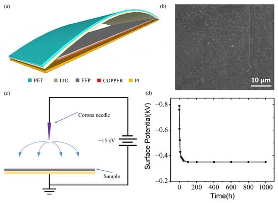
Figure 1.
Fabrication and characterization of the electret nanogenerator (ENG). (a) Schematic diagram of the ENG. Scanning electron microscope (SEM) surface morphology, (b) electret charge injection method, and (c) surface potential decay with time (d) of fluorinated ethylene propylene (FEP) electret film.
FEP is a typical electret material that requires polarization for long-term charge storage. Figure 1c is a charge injection method for electret film. A high voltage source of −15 kV was applied to the corona needle. When the voltage between the corona needle and FEP film exceeded the Paschen threshold voltage, air gap ionization would occur, resulting in a large number of charged ions. Under the action of the electric field, these ion charges were accelerated and moved to the electret, and they could be injected and trapped in the near surface of the electret. The existence of the real charges in the electret was the origin of electrostatic induction for the normal operation of the generator. Figure 1d illustrates the curve of surface potential versus time of an as-fabricated FEP electret after corona poling, in which it could be found that the surface potential decreased exponentially in 24 h but could be stable with negligible decrease in the following 1000 h. It is generally believed that some electrons are trapped and neutralized by impurities or opposite charges in the electret. Subsequently, the electret surface potential did not attenuate too much and remained at −350 V. According to electrostatic theory, the stored charges in electrets are proportional to the surface potential, which is a key factor when determining the outputs of the electret generators.
Figure 2 is a schematic diagram of the working principle of the ENG. In Figure 2aI, the electret generator is in an initial equilibrium state, and no current flows through the applied load. An electric potential difference is established between the upper and bottom electrodes, at which point the air gap is at the maximum value. When the external force is applied (Figure 2aII), the air gap between the upper electrode and the electret film is reduced, and thus positive charges induced on the upper electrode are increased. As a result, the electric potential difference begins to decrease, and electrons will flow from the upper electrode to the bottom electrode, generating a positive current signal through the load resistor until the upper electrode and the FEP film are fully contacted, as depicted in the new equilibrium state in Figure 2aIII. When the pressing force is removed (as shown in Figure 2aIV), the air gap becomes larger, and the induced positive charge of the upper electrode decreases, generating a negative current signal through the load resistor. Through the whole working process, the FEP electret film acts as an electron pump that prompts electrons to move back and forth between the upper and bottom electrodes.
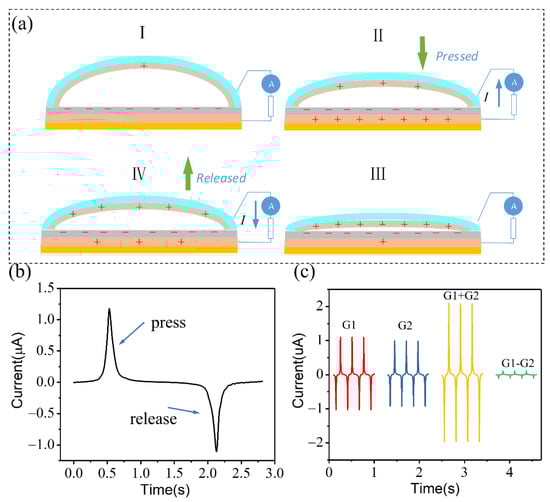
Figure 2.
Working principle of the ENG. (a) Schematic diagram illustrates the electricity generation process of the ENG when it is at (I) the original, (II) the pressing, (III) the equilibrium, and (IV) the releasing states, respectively. (b) Short-circuit currents of the ENG when it is forward-connected to the measurement system. (c) Short-circuit currents of the two ENGs in parallel (G1 + G2) and reverse parallel (G1 − G2) connection.
As shown in Figure 2b, for a given stimulated force and frequency of 4 N and 4 Hz, the peak short-circuit current (ISC) for our electret generator reached 1.18 µA, verifying that the measured output signal was generated from the ENG rather than from the measurement system. Figure 2c is short-circuit current measurements for positive connections of upper and lower electrodes of generators. It was found that if two electret generators (G1 and G2) were connected in parallel, the current in the loop would be the sum of the output of the two generators (G1 + G2), and when the two generators were connected in reverse polarity, the current in the loop would be the difference between the output of the two generators (G1 − G2).
In order to systematically study the electrical output performance of the ENG, different forces and frequencies were applied to the generator by a vibrator, as shown in Figure 3. Details on sample preparation as well as the measurement setup are presented in the Materials and Methods section. Repetitive pressure loading and unloading were realized through a linear motor that provided a precisely controlled reciprocating motion. Firstly, the excitation frequency of the vibrator was fixed to 4 Hz, and the generator was short-circuited. The output current curve of ENG under different forces is shown in Figure 3a. With the increase of force, the peak value of the short-circuit current increased from 0.63 μA at 1 N to 1.14 μA at 5 N, as shown in Figure 3c. By integrating the output current, the value of transfer charge ΔQ could be obtained, which increased with the increase of force (Figure 3b) and increased from 18.8 nC at 1 N to 21.27 nC at 5 N (Figure 3c).
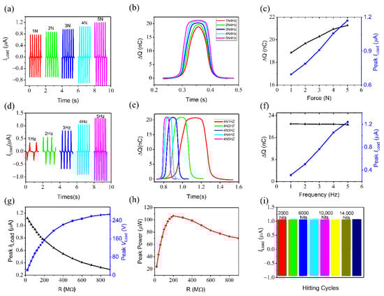
Figure 3.
Electrical performance of an ENG. Load current (a), corresponding transferred charges ∆Q (b), and peak load current (c) of an ENG varied at a given frequency of 4 Hz and different stimulated force. Load current (d), corresponding transferred charges ∆Q (e), and peak load current (f) of an ENG varied at a given force of 4 N and different stimulated frequency. Peak load current and voltage (g) and peak power (h) of an ENG with different external loads. (i) The durability of the ENG with a continuous loading/unloading of a periodic force of 4 N and frequency of 4 Hz.
At the fixed frequency 4 HZ, the output short circuit current of ENG under different pressing forces is shown in Figure 3d. As can be seen in Figure 3f, with the increase of pressing frequency, the peak value of short circuit current increased from 0.31 μA at 1 N to 1.23 μA at 5 N. However, the corresponding transfer charge ΔQ stayed at a constant value of about 20.8 nC (as shown in Figure 3e,f), which was mainly due to the constant change of air gap thickness in the generator under the condition of fixed force, and the transfer charge of the upper and lower generators was basically the same.
Load characteristic was an important index for the electrical performance of the ENG. At a fixed frequency of 4 Hz and force of 4 N, different load resistances were inserted into the upper and lower electrodes of the generator to measure the load curve, as shown in Figure 3g,h. With the increase of load resistance, the load voltage increased gradually from 21.4 V of 20 MΩ to 267.1 V of 900 MΩ, while the growth rate of voltage decreased. This was because when the resistance was infinite, the voltage reached saturation. The voltage at this time was called open-circuit voltage. The load current decreased from 1.07 μA of 20 MΩ to 0.28 μA of 900 MΩ. Through the load curve of current and voltage, the corresponding load power curve was calculated. It could be seen that at 200 MΩ, the load power was the largest with a power density of 20.6 mW/cm2. Finally, to further investigate the stability of the ENG, we used the exciter to continuously oscillate more than 16,000 cycles with 4 Hz frequency and 4 N compression force. It can be seen in Figure 3i that the output performance of the generator had no attenuation during the whole test process, which indicated that the ENG was extremely repeatable and stable.
Under the pressure of external force, an ENG can generate an electrical signal output without an external power supply, and the output performance will change correspondingly with the change in pressing frequency and force. Compared with other sensors, the application of ENG for self-powered active sensors has broader application prospects. In this paper, seven ENGs were integrated in flexible pressure sensors to make a flexible keyboard, as shown in Figure 4. Figure 4a is a general block diagram of the entire keyboard. The signal output of the key sensor was connected to the comparator array. The output of the comparator was connected to the port pin of the MCU and simultaneously input to the input-port of the NAND gate, and the NAND output was connected to the external interrupt pin of the MCU. External power modules needed to provide power to the MCU, the comparator array, and the NAND gate. The MCU could sense in real time whether the keyboard’s keys were pressed and thus emit different tones, which were output through the speakers.
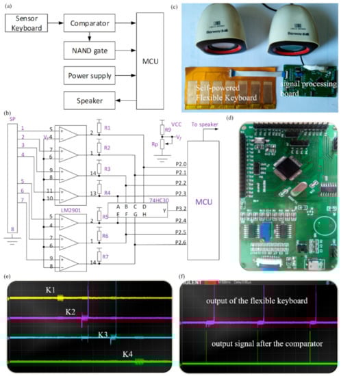
Figure 4.
Application of an ENG for a flexible and self-powered electronic piano. (a) Block diagram of the flexible electronic piano. (b) Detailed circuit of the signal processing board. (c) Photograph of a flexible electronic piano with seven self-powered sensors integrated on the same flexible PCB. (d) Photograph of signal processing board based on PCB. (e) Oscilloscope signal output of the flexible keyboard pressed by external force. (f) Comparison between the direct output signal and the processed signal (the output after comparison with the reference voltage on the signal processing board).
A detailed schematic diagram of the signal processing circuit is shown in Figure 4b. Seven ENG electrodes were jointly connected to a common ground (the 8th foot of the SP terminal), and the other electrodes were connected to the 1st to 7th ports of the SP terminal, respectively, thus connecting to the in-phase input of the comparator LM2901. While the inverted input terminal of LM2901 was connected with a comparative voltage Vf (which can be adjusted by variable resistance RP), the comparative signal was pulled up through a 5.1 kΩ resistance and then connected to the P2.0–P2.6 pins of the MCU controller. It was also connected to the input terminal of 8-input NAND gate 74HC30. The output of the 74HC30 was connected to the external interrupt pin P3.2 of the microcontroller (INTO pin). When a certain button of the keyboard was pressed, a certain voltage output was generated on the corresponding SP terminal. By adjusting the magnitude of the comparison voltage Vf, the LM2901 would output a low level. Next, the 74HC30 output was converted from a low level to a high level, thereby generating a rising edge signal and then requesting an external interrupt from the MCU. The MCU determined whether there was an external key to determine whether a key was pressed. If a key was pressed, the P2.0–P2.6 port voltage was immediately scanned to know which key was pressed, thereby performing the corresponding features.
The optical photography of the assembled electronic piano is shown in Figure 4c, which consists of three parts: a flexible key, a signal processing board, and an external speaker. By pressing the random K2 and K3 keys on the flexible keys with our fingers, we observed the corresponding signal output on the oscilloscope (Figure 4e). To eliminate signal interference, we connected the output signal to the comparator before accessing the oscilloscope. It can be clearly seen that the output signal is much clearer with comparator access than without comparator access, which is shown in Figure 4f. In the MCU programming keyboard execution program, if the output of the seven keys pressed was set to “do re mi fa so la it” of the note, the keyboard could be played.
4. Conclusions
In summary, a flexible FEP electret nanogenerator was fabricated that could generate an effective electrical signal output under the stimulation of external force without an additional power supply. The output electrical performances of ENGs under different external pressures and frequencies were systematically characterized. At a fixed frequency of 4 Hz and force of 4 N with a matched load resistance of 200 MΩ, an output power density of 20.6 mW/cm2 could be achieved. Though the implementation of a signal processing circuit, ENG-based, self-powered pressure sensors have been demonstrated for a self-powered, flexible electronic piano. This work provides a new strategy using electret nanogenerators for self-powered sensor networks and portable electronics.
Author Contributions
Data curation, Z.X.; Funding acquisition, Q.Z.; Methodology, W.C.; Project administration, Y.G.; Software, C.G.; Supervision, B.W.; Writing—original draft, Y.X.; Writing—review & editing, J.W. and B.W. All authors have read and agreed to the published version of the manuscript.
Funding
This research was funded by the National Natural Science Foundation of China (61705064; 61972136; 61471161), the Henan Provincial Science and Technology Research Project (212102210470), the Program for Youth Scholar Teachers Supporting Plan in Universities of Henan Province (2018GGJS157), the Natural Science Foundation of Hubei Province (2020CFB345; 2018CFB773) and the Hubei Provincial De-partment of Education Outstanding Youth Scientific Innovation Team Support Foundation (T201410).
Institutional Review Board Statement
Not applicable.
Informed Consent Statement
Not applicable.
Data Availability Statement
Not applicable.
Acknowledgments
This work was financially supported by the National Natural Science Foundation of China (61705064; 61972136; 61471161), the Henan Provincial Science and Technology Research Project (212102210470), the Program for Youth Scholar Teachers Supporting Plan in Universities of Henan Province (2018GGJS157), the Natural Science Foundation of Hubei Province (2020CFB345; 2018CFB773) and the Hubei Provincial Department of Education Outstanding Youth Scientific Innovation Team Support Foundation (T201410).
Conflicts of Interest
The authors declare no conflict of interest.
References
- Chu, S.; Cui, Y.; Liu, N. The path towards sustainable energy. Nat. Mater. 2017, 16, 16–22. [Google Scholar] [CrossRef] [PubMed]
- Safaei, M.; Sodano, H.A.; Anton, S.R. A review of energy harvesting using piezoelectric materials: State-of-the-art a decade later (2008–2018). Smart Mater. Struct. 2019, 28, 113001. [Google Scholar] [CrossRef]
- Huang, L.; Lin, S.; Xu, Z.; Zhou, H.; Duan, J.; Hu, B.; Zhou, J. Fiber-based energy conversion devices for human-body energy harvesting. Adv. Mater. 2019, 32, 1902034. [Google Scholar] [CrossRef] [PubMed]
- Invernizi, F.; Dulio, S.; Patrini, M.; Guizzetti, G.; Mustarelli, P. Energy harvesting from human motion: Materials and techniques. Chem. Soc. Rev. 2016, 45, 5455–5473. [Google Scholar] [CrossRef]
- Wang, Z.L. Triboelectric Nanogenerators As New Energy Technology for Self-Powered Systems and as Active Mechanical and Chemical Sensors. ACS Nano 2013, 7, 9533–9557. [Google Scholar] [CrossRef]
- Lin, J.; Huang, H.; Li, Y.; Tai, J.; Liu, L. Electronic piano playing robot. In Proceedings of the 2010 International Symposium on Computer, Communication, Control and Automation (3CA), Tainan, Taiwan, 5–7 May 2010; pp. 353–356. [Google Scholar]
- McPherson, A. The magnetic resonator piano: Electronic augmentation of an acoustic musical instrument. J. New Music Res. 2010, 39, 189–202. [Google Scholar] [CrossRef]
- O’modhrain, S. A Framework for the Evaluation of Digital Musical Instruments. Comput. Music J. 2011, 35, 28–42. [Google Scholar] [CrossRef]
- Wang, Z.L.; Chen, J.; Lin, L. Progress in Triboelectric Nanogenerators as a New Energy Technology and Self-Powered Sensors. Energy Environ. Sci. 2015, 8, 2250–2282. [Google Scholar] [CrossRef]
- Hou, C.; Wang, H.; Zhang, Q.; Li, Y.; Zhu, M. Highly Conductive, Flexible, and Compressible All-Graphene Passive Electronic Skin for Sensing Human Touch. Adv. Mater. 2014, 26, 5018–5024. [Google Scholar] [CrossRef]
- Pan, L.; Chortos, A.; Yu, G.; Wang, Y.; Isaacson, S.; Allen, R.; Shi, Y.; Dauskardt, R.; Bao, Z. An Ultra-Sensitive Resistive Pressure Sensor Based on Hollow-Sphere Microstructure Induced Elasticity in Conducting Polymer Film. Nat. Commun. 2014, 5, 3002. [Google Scholar] [CrossRef] [PubMed]
- Wang, X.; Gu, Y.; Xiong, Z.; Cui, Z.; Zhang, T. Silk-Molded Flexible, Ultrasensitive, and Highly Stable Electronic Skin for Monitoring Human Physiological Signals. Adv. Mater. 2014, 26, 1336–1342. [Google Scholar] [CrossRef]
- Pang, C.; Lee, G.-Y.; Kim, T.-i.; Kim, S.M.; Kim, H.N.; Ahn, S.-H.; Suh, K.-Y. A Flexible and Highly Sensitive Strain-Gauge Sensor Using Reversible Interlocking of Nanofibres. Nat. Mater. 2012, 11, 795–801. [Google Scholar] [CrossRef]
- Chen, L.Y.; Tee, B.C.-K.; Chortos, A.L.; Schwartz, G.; Tse, V.; Lipomi, D.J.; Wong, H.-S.P.; McConnell, M.V.; Bao, Z. Continuous Wireless Pressure Monitoring and Mapping with Ultra-Small Passive Sensors for Health Monitoring and Critical Care. Nat. Commun. 2014, 5, 5028. [Google Scholar] [CrossRef] [PubMed]
- Lipomi, D.J.; Vosgueritchian, M.; Tee, B.C.; Hellstrom, S.L.; Lee, J.A.; Fox, C.H.; Bao, Z. Skin-Like Pressure and Strain Sensors Based on Transparent Elastic Films of Carbon Nanotubes. Nat. Nanotechnol. 2011, 6, 788–792. [Google Scholar] [CrossRef]
- Park, S.; Kim, H.; Vosgueritchian, M.; Cheon, S.; Kim, H.; Koo, J.H.; Kim, T.R.; Lee, S.; Schwartz, G.; Chang, H.; et al. Stretchable Energy-Harvesting Tactile Electronic Skin Capable of Differentiating Multiple Mechanical Stimuli Modes. Adv. Mater. 2014, 26, 7324–7332. [Google Scholar] [CrossRef]
- Yao, S.; Zhu, Y. Wearable Multifunctional Sensors Using Printed Stretchable Conductors Made of Silver Nanowires. Nanoscale 2014, 6, 2345–2352. [Google Scholar] [CrossRef]
- Wu, W.; Wen, X.; Wang, Z.L. Taxel-Addressable Matrix of Vertical-Nanowire Piezotronic Transistors for Active and Adaptive Tactile Imaging. Science 2013, 340, 952–957. [Google Scholar] [CrossRef] [PubMed]
- Persano, L.; Dagdeviren, C.; Su, Y.; Zhang, Y.; Girardo, S.; Pisignano, D.; Huang, Y.; Rogers, J.A. High Performance Piezoelectric Devices Based on Aligned Arrays of Nanofibers of Poly (vinylidenefluoride-co-trifluoroethylene). Nat. Commun. 2013, 4, 1633. [Google Scholar] [CrossRef] [PubMed]
- Sharma, T.; Je, S.-S.; Gill, B.; Zhang, J.X. Patterning Piezoelectric Thin Film PVDF–TrFE Based Pressure Sensor for Catheter Application. Sens. Actuators A 2012, 177, 87–92. [Google Scholar] [CrossRef]
- Fan, F.R.; Lin, L.; Zhu, G.; Wu, W.; Zhang, R.; Wang, Z.L. Transparent Triboelectric Nanogenerators and Self-Powered Pressure Sensors Based on Micropatterned Plastic Films. Nano Lett. 2012, 12, 3109–3114. [Google Scholar] [CrossRef] [PubMed]
- Lin, L.; Xie, Y.; Wang, S.; Wu, W.; Niu, S.; Wen, X.; Wang, Z.L. Triboelectric Active Sensor Array for Self-Powered Static and Dynamic Pressure Detection and Tactile Imaging. ACS Nano 2013, 7, 8266–8274. [Google Scholar] [CrossRef] [PubMed]
- Luo, J.; Fan, F.R.; Zhou, T.; Tang, W.; Xue, F.; Wang, Z.L. Ultrasensitive Self-Powered Pressure Sensing System. Extrem. Mech. Lett. 2015, 2, 28–36. [Google Scholar] [CrossRef]
- Zhu, G.; Yang, W.Q.; Zhang, T.; Jing, Q.; Chen, J.; Zhou, Y.S.; Bai, P.; Wang, Z.L. Self-Powered, Ultrasensitive, Flexible Tactile Sensors Based on Contact Electrification. Nano Lett. 2014, 14, 3208–3213. [Google Scholar] [CrossRef] [PubMed]
- Wang, X.; Zhang, H.; Dong, L.; Han, X.; Du, W.; Zhai, J.; Pan, C.; Wang, Z.L. Self-Powered High-Resolution and Pressure-Sensitive Triboelectric Sensor Matrix for Real-Time Tactile Mapping. Adv. Mater. 2016, 28, 2896–2903. [Google Scholar] [CrossRef]
- Flynn, A.M.; Sanders, S.R. Fundamental Limits on Energy Transfer and Circuit Considerations for Piezoelectric Transformers. IEEE Trans. Power Electron. 2002, 17, 8–14. [Google Scholar] [CrossRef]
- Fang, J.; Niu, H.; Wang, H.; Wang, X.; Lin, T. Enhanced Mechanical Energy Harvesting Using Needleless Electrospun Poly (vinylidene fluoride) Nanofibre Webs. Energy Environ. Sci. 2013, 6, 2196–2202. [Google Scholar] [CrossRef]
- Wang, Z.L. Self-Powered Nanotech. Sci. Am. 2008, 298, 82–87. [Google Scholar] [CrossRef]
- Zhu, G.; Bai, P.; Chen, J.; Jing, Q.; Wang, Z.L. Triboelectric Nanogenerators as a New Energy Technology: From Fundamentals, Devices, to Applications. Nano Energy 2015, 14, 126–138. [Google Scholar] [CrossRef]
- Sessler, G.M. Electrets: Recent Developments. J. Electrost. 2001, 51, 137–145. [Google Scholar] [CrossRef]
- Boland, J.; Chao, Y.H.; Suzuki, Y.; Tai, Y. Micro Electret Power Generator. In Proceedings of the IEEE International Conference on Micro Electro Mechanical Systems (MEMS), Kyoto, Japan, 2 April 2003; pp. 538–541. [Google Scholar]
- Wang, B.; Zhong, J.; Zhong, Q.; Wu, N.; Cheng, X.; Li, W.; Liu, K.; Huang, L.; Hu, B.; Zhou, J. Sandwiched Composite Fluorocarbon Film for Flexible Electret Generator. Adv. Electron. Mater. 2016, 2, 1500408. [Google Scholar] [CrossRef]
- Wang, S.; Xie, Y.; Niu, S.; Lin, L.; Liu, C.; Zhou, Y.S.; Wang, Z.L. Maximum Surface Charge Density for Triboelectric Nanogenerators Achieved by Ionized-Air Injection: Methodology and Theoretical Understanding. Adv. Mater. 2014, 26, 6720–6728. [Google Scholar] [CrossRef] [PubMed]
- Wang, S.; Lin, L.; Wang, Z.L. Nanoscale tricoelectric-effect-enabled energy conversion for sustainably powering portable electronics. Nano Lett. 2012, 12, 6339–6346. [Google Scholar] [CrossRef] [PubMed]


Publisher’s Note: MDPI stays neutral with regard to jurisdictional claims in published maps and institutional affiliations. |
© 2021 by the authors. Licensee MDPI, Basel, Switzerland. This article is an open access article distributed under the terms and conditions of the Creative Commons Attribution (CC BY) license (http://creativecommons.org/licenses/by/4.0/).