1. Introduction
The shredding of material, similar to crushing and squeezing out, is one of the main technological operations performed in the agri-food, chemical, power and construction industries. These processes consist of splitting material into smaller parts with the use of working elements of a machine, which overcome the cohesion forces of the material’s particles. The effect of these processes is obtaining material shredded in the crushing and squeezing out processes, and oils and cold-pressed pulp in the process of kneading [
1,
2,
3,
4,
5]. Material obtained in such a manner can directly, or after processing, be used for consumption purposes, for fodder for animals, as an energetic material during its combustion, as an additive to fossil fuels or in the construction industry [
6,
7,
8,
9,
10,
11,
12,
13].
The processes of shredding and crushing are the most popular. When selecting the method of shredding, one should take into consideration the mechanical properties of the material to be shredded, choosing a manner of the working elements’ interaction to obtain the required degree of grain material shredding at the lowest possible stress levels to avoid damage. The roller mills, in particular the roller-bowl mills, have found their extended application in the agri-food industry. They are used for the milling and crushing of cereal grain, fertilizers and mineral raw materials, among the others.
The essence of the milling process in the roller mills consists of a mutual interaction of mechanical forces exerted on two surfaces, where one of them rolls on the other one, and between them there is the milled and shredded material. The feed forces are exerted from the mill’s grinding media by the gravity forces, springs or a hydraulic clamp. The bodies of revolution in the form of rolls, toruses, tapers or pebbles act as grinding media. Grinding media always roll along the bearing surface, which is made of bowls of flat or shaped materials. In the known designs of mills for brands such as Loesche, Pfeiffer, Polysius and others, the grinding media have the diameter from 200 to 2500 mm [
14,
15,
16]. They guarantee the material’s crushing effectiveness on the level from 2 to 500 t·h
−1.
For the purposes of selecting the design features and parameters of the mills of that type, the guidelines for their design are provided in the available literature [
14,
16]:
The roll’s suspension system should be equipped with connecting members which fulfill the perpendicularity requirement with reference to the normal operation of centrifugal force,
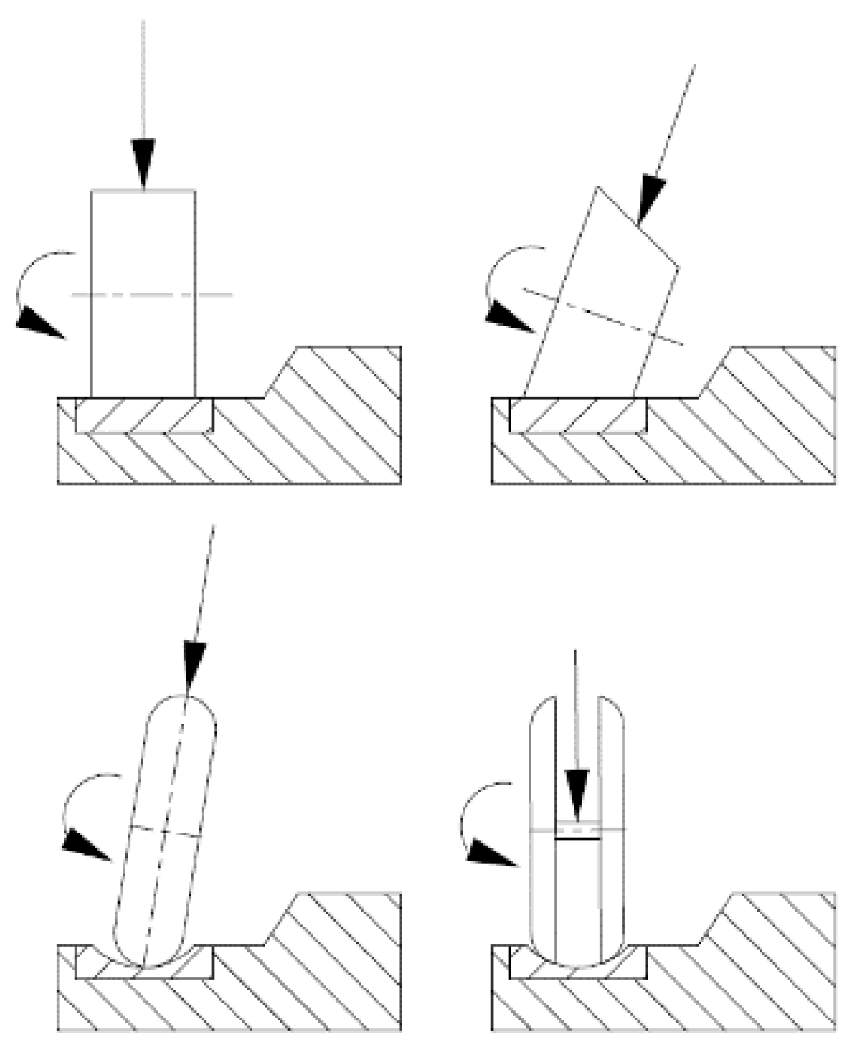
The rolls should be in the shape of a truncated cone, full torus or divided torus,
The relationship of the width s of the roll to its diameter d should amount to between 0.27 to 0.32, depending on the mill’s type,
There exist the limit values of bowls or rolls’ angular velocities, depending on their geometrical features, where these speeds increase together with the increase of the mill’s dimensions. In the case of bigger mills, the milled material has to overcome the frictional resistance along the longer bowl surface.
The maximum pressure of rolls, having the diameter
d on a bowl, may be determined based on the Börner’s dependence [
14]:
for the mills of the Pfeiffer type:
for the mills of the Loesche type:
In the opinion of the study’s authors, there is a failure to consider the maximum pressure of rollers and their angle speeds for the roller mill design. This is of special importance in the reversed system, when the bowl is motionless and the rollers move along the bowl in the rolling motion on a constant radius.
That is why the development of the mathematical model for the loading of the bowl from the roller assembly in the roller mill and the selected simulation calculations are the basic purposes of this study.
2. Materials and Methods
On the stage of development of the mill bowl’s mathematical loading, there have been two assumed premises, from which the following have resulted:
Considering the description of all the important factors from the point of the view of the internal bowl’s loading, features and design parameters of the milling roller and the axis it is mounted on;
Application of a simple mathematical recording, accurately mapping the real conditions of the roller mill’s operation.
Exemplary schemes of design solutions of the milling rollers are presented in
Figure 1.
Figure 2 presents the scheme of the bowl’s loading with the roller assembly and its axis, where it has been assumed that the point of tangency
A of the roller with the background is in a given moment motionless, and the straight line connecting the points
O and
A is the temporary axis of the roller’s rotation.
The value of the reaction force Pmax may be calculated in two ways. The first consists of the fact that we disregard the rotation of a fixed point of a milling roller, and then we have:
where:
G–weight of the roller,
R–resultant loading of the roller’s axis,
m–mass of the roller
–gravitational acceleration,
q–constant loading of the roller’s axis.
In the second manner of the reaction force’s
Pmax calculation we consider in calculations the roller’s rotation on a fixed point. It is particularly important when designing mills equipped with rollers with big dimensions, the diameter of which have even been 2500 mm. According to the
Figure 1, between
ω1 and
ω2, there occurs a dependence:
where:
ω1–the roller’s angular velocity in relation to the axis z,
ω2–the roller’s angular velocity in relation to its own axis of revolution, which is axis y,
The following dependence may be applied to determine the force
Pmax:
According to which, the differential coefficient in relation to the time of angular momentum of the material point system in relation to any optional motionless pole equals the geometrical sum of all the external forces’ moments in relation to the same pole. However, the components of the angular momentum
K0 may be calculated by determining the components
Kx,
Ky, and
Kz from the dependence:
where:
Ix,y,z–moments of inertia of a body making the rotational movement in relation to the axes x, y and z,
ωx,y,z–projections of the angular speeds ω of vectors on the axes x, y, z.
According to
Figure 2, we have:
ωx = 0;
ωy = −
ω2;
ωz =
ω1 that is respectively:
Accordingly, we receive the equation:
Due to the fact that in the milling process assumes ω = const, the value of the angular momentum also has not changed, because K0 = const.
Substituting for the Equation (7) instead for
K0 the equation from formula (8), we receive:
The second constituent of the Equation (10) equals zero as the product of two parallel vectors and of
which is why, finally:
For the mill’s milling roller there are three external forces with reference to the point 0:
gravity force of the milling roller (m·g),
reaction force of the mill’s bowl (Pmax),
reaction force of the milling roller’s loading from the driving axle .
It has been assumed in the discussions that the axle driving the roller is supported in two points: point 0 and in the middle of the roller’s width. That is why:
Substituting the expression (12) to (11), we find:
Assuming that the milling roller has the shape of a cylinder (
)
and
, we find:
The expression constitutes an additional value of a dynamic reaction because of the roller’s rotation around a fixed point. It may be assumed that the values have an impact on the total loading of the mill’s bowl, which is why, in the opinion of the authors of the study, at this stage of the mills’ design the dynamic reaction should not be omitted in case the working elements rotate around a fixed point.
3. Results
The selected simulation calculations aimed at determining the dynamic reaction
κ were conducted for different design features and parameters of the milling rollers made of carbon steel of the mass density of ρ
st = 7850 kg·m
−3 and of cast iron of the mass density of ρ
z = 7500 kg·m
−3. For calculation purposes it has been assumed that the diameters of the rollers
d in the mill were within the scope from 270 to 320 mm at their width
s = 100 mm (
Table 1). The assumed system of values
d and
s meet the guidelines concerning roller mills’ design, according to which
s/d = 0.27–0.32. Moreover, it has been assumed that the angular speed of the roller
ω1 with reference to the axle falls into the range of values from 0.7 to 1.6 rad·s
−1 and that the dimensions
a and
b (in accordance with the
Figure 2) respectively assume the values
a = 500 mm and
b = 550 mm.
Detailed values of simulation calculations of the reaction force’s value
Pmax, of additional dynamic reaction
κ and its percentage share in the reaction force’s value
Pmax for individual design features and parameters are presented in the
Table 1,
Table 2 and
Table 3. In the mentioned tables, letters A–F mark the milling rollers made of carbon steel N9E and of cast iron EN-GJS-700-2 in sequence from the lowest to the highest diameter
d.
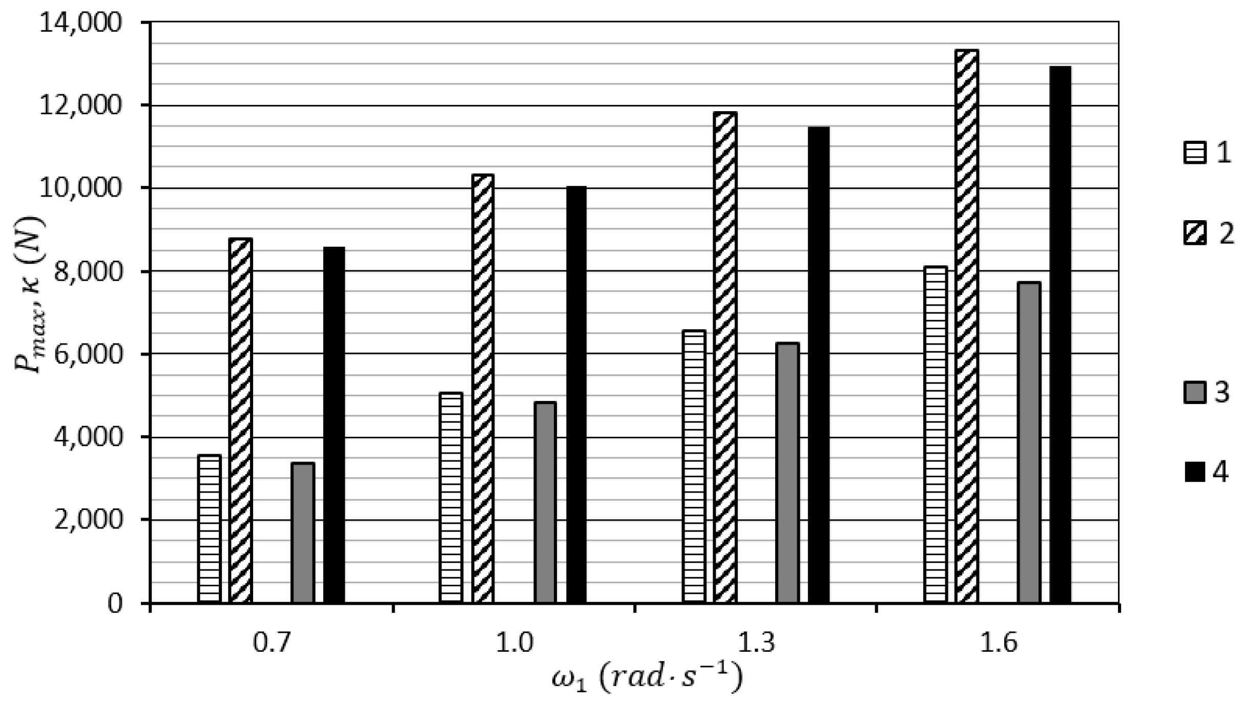
In
Figure 3, the impact of the milling roller’s mass
m made of steel on the value of the dynamic reaction
κ for the assumed angular speeds
ω1 is presented.
In
Figure 4, the impact of the value of the milling roller’s mass
m on the reaction value
κ when the roller is made of cast iron is presented.
.
From the obtained simulation calculation results (
Figure 3 and
Figure 4), it unambiguously shows that together with the increase of the roller’s weight
m and its angular speed
ω1, the reaction value
κ increases approximately in the quadratic function, where the highest values of
κ = 8080.64 N for the roller made of steel and for
κ = 7720.96 N for the roller made of cast iron were received for the roller’s angular speed
ω1 = 1.6 rad·s
−1.
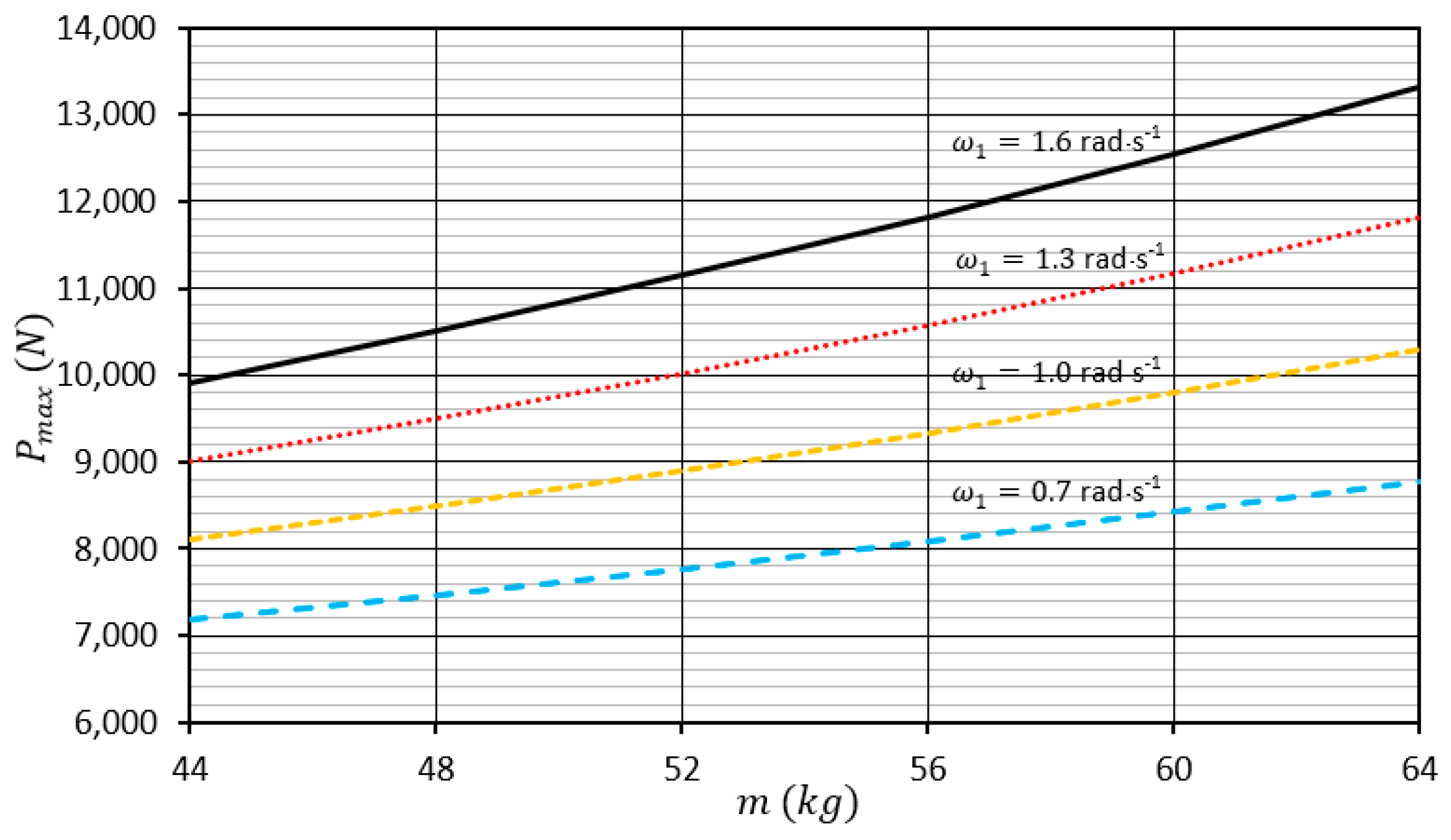
In
Figure 5, the impact of the milling roller’s weight
made of steel on the value of reaction
Pmax for angular speeds
ω1 is presented.
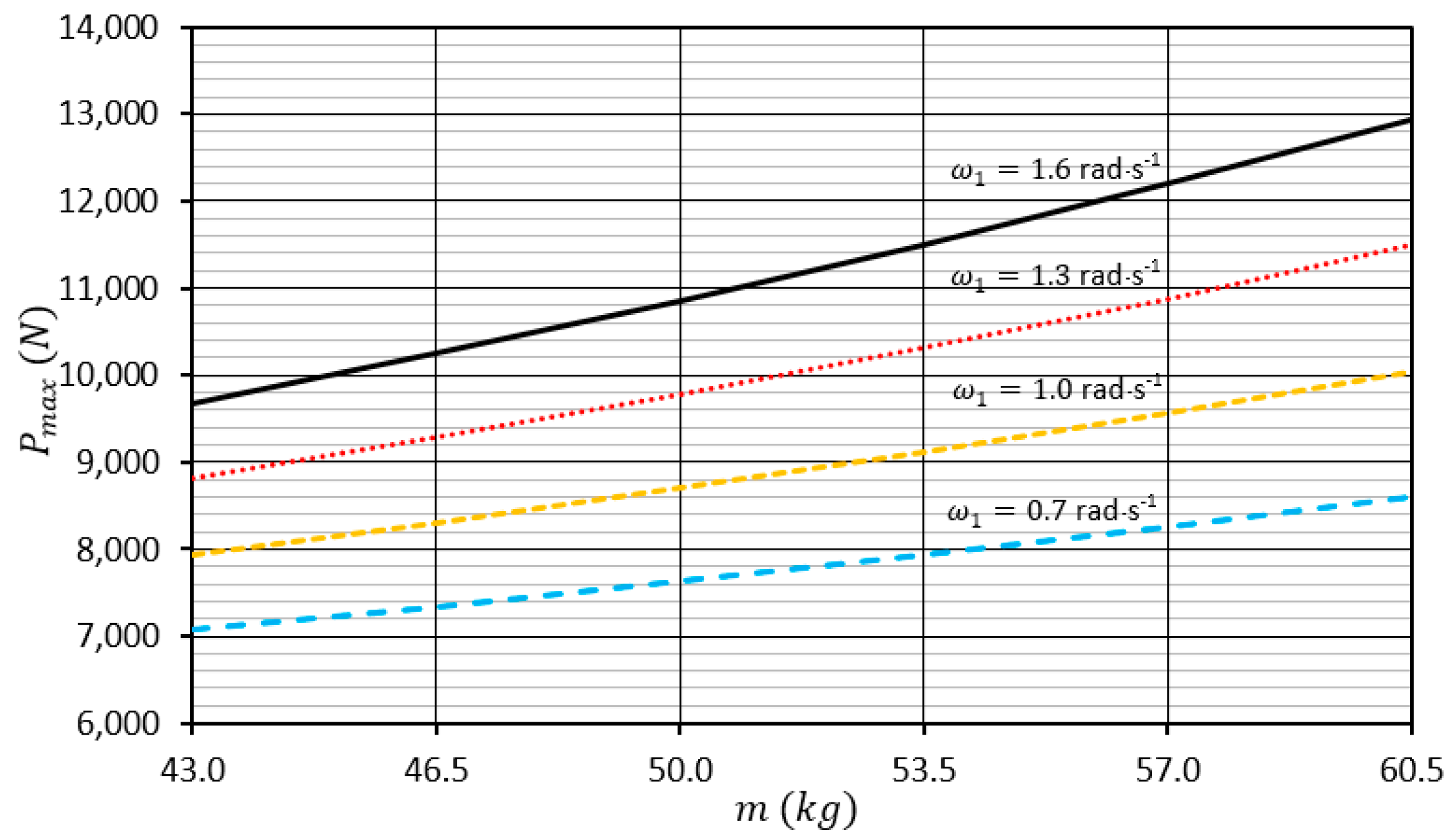
However, in
Figure 6 the impact of the milling roller mass’ value
m on the reaction value
Pmax when the roller is made of cast iron is presented.
4. Discussion
From the analysis of the results presented in
Figure 5 and
Figure 6, it unambiguously shows that together with the increase of the roller’s weight
m and its angular speed
ω1, the reaction value
Pmax increases approximately in the quadratic function. The highest values
Pmax assumes for the angular speed of the roller
ω1 = 1.6 rad·s
−1, respectively, and
Pmax = 13,323.85 N for a roller made of steel and
Pmax = 12,936.60 N for a roller made of cast iron.
In
Figure 7, the chart of percentage shares of dynamic reaction κ in the complete value of reaction
Pmax, respectively, for both the roller materials is presented.
From the analysis of the chart in
Figure 7, it unambiguously shows that the share of
κ is very big and for the variable system at the roller’s angular speed
ω1 = 1.3 rad·s
−1 and the angular speed
ω1 = 1.6 rad·s
−1, it may even exceed 50%.
In order to compare the obtained research and calculation results with those available in the literature, the authors state that others have not yet analyzed the effect of the additional loading of mill working elements due to the occurrence of the spherical motion effect. Only general mathematical models in this field have been presented in the literature [
16,
17,
18,
19,
20].
The authors’ calculation model presented in this paper takes into account the gyroscopic phenomenon taking place during the crushing process. This results in an increased loading of the mill bowl with an additional dynamic reaction from the working unit, which may account for 60.65% of the total load. Therefore, using the calculation model proposed in the article, one gets a full picture of the actual loads on the working unit and the mill bowl, which should translate into a proper selection of their design parameters.
5. Conclusions
The processing of agri-food, chemical, power and construction industries’ raw materials products are being conducted, among the others, in gravitational, mixing, impact, vibration or roller mills. Over the last few years their big development has been observed, which has been aimed at the increase of their output and limitation of the unit energy consumption while maintaining the correct shredding degree of the milled material. Quick design of new mill constructions, in particular for roller ones, requires the development of adequate mathematical models. Within the frames of the study, a mathematical model of loading of the bowl from the working assembly of the roller for a roller mill was developed. It comprised an additional member of dynamic reaction κ, which has been so far omitted in the professional literature at the stage of design calculations of roller mills, and its share in the bowl’s calculations is considerable. The conducted simulation calculations on the developed mathematical model have shown that, for example, for a steel roller N9E of the weight of m = 63.13 kg and its angular speed ω1 = 1.6 rad·s−1, its share amounts to 60.65%. However, for a roller made of cast iron EN-GJS-700-2 of the weight of m = 60.32 kg and an angular speed ω1 = 1.6 rad·s−1, it amounts to 59.68%.
Author Contributions
Conceptualization, M.Z. and A.B.; methodology, A.B.; formal analysis, M.Z. and L.H.; investigation, A.B.; writing—original draft preparation, M.Z. and A.B.; writing—review and editing, M.Z. and L.H.; visualization, M.Z.; supervision, A.B. All authors have read and agreed to the published version of the manuscript.
Funding
The research was carried out with a grant from the Minister of Science and Higher Education as part of scientific research conducted at the Faculty of Mechanical Engineering of the UTP.
Institutional Review Board Statement
The research conducted as part of the results presented in the article did not involve humans or animals.
Informed Consent Statement
Not applicable.
Data Availability Statement
All the computational data from mathematical simulations are included in the article.
Acknowledgments
The article has been written in bilateral co-operation of the UTP University of Science and Technology in Bydgoszcz, Poland and the Slovak University of Agriculture in Nitra, Slovakia. The co-operation was based on funds, among the others, from the Polish National Agency for Academic Exchange NAWA within the frames of the project no PPN/BIL/2018/1/00096/U/00001.
Conflicts of Interest
The authors declare no conflict of interest and the funders had no role in the design of the study, in the writing of the manuscript, or in the decision to publish the results.
References
- Bochat, A. Theory and construction of cutting units of agricultural machines. In UTP University of Science and Technology; UTP: Bydgoszcz, Poland, 2010. [Google Scholar]
- Tomporowski, A.; Flizikowski, J.; Kruszelnicka, W. A new concept of roller-plate mills. Przem. Chem. 2017, 96, 1750–1755. [Google Scholar]
- Kruszelnicka, W. A New Model for Environmental Assessment of the Comminution Process in the Chain of Biomass Energy Processing. Energies 2020, 13, 330. [Google Scholar] [CrossRef]
- Kruszelnicka, W.; Baldowska-Witos, P.; Kasner, R.; Flizikowski, J.; Tomporowski, A.; Rudnicki, J. Evaluation of emissivity and environmental safety of biomass grinders drive. Przem. Chem. 2019, 98, 1494–1498. [Google Scholar]
- Kruszelnicka, W.; Kasner, R.; Bałdowska-Witos, P.; Flizikowski, J.; Tomporowski, A. The Integrated Energy Consumption Index for Energy Biomass Grinding Technology Assessment. Energies 2020, 13, 1417. [Google Scholar] [CrossRef]
- Dhaundiyal, A.; Singh, S.B. Approximations to the Non-Isothermal Distributed Activation Energy Model for Biomass Pyrolysis Using the Rayleigh Distribution. Acta Technol. Agric. 2017, 20, 78–84. [Google Scholar] [CrossRef]
- Hlavac, P.; Bozikova, M.; Petrovic, A. Selected Physical Properties Assessment of Sunflower and Olive Oils. Acta Technol. Agric. 2019, 22, 86–91. [Google Scholar]
- Muslewski, L.; Knopik, L.; Landowski, B.; Polishchuk, O. Analysis of assessment criteria for selected systems of transport means operation. In Proceedings of the 17th International Conference Diagnostics of Machines and Vehicles, Bydgoszcz, Poland, 25–26 September 2018; Volume 182. [Google Scholar]
- Kaszkowiak, J.; Hujo, L.; Jablonicky, J. Impact of the content of alcohol in petroleum on the level of an unsupercharged engine’s noise. In Proceedings of the 18th International Conference Diagnostics of Machines and Vehicles, Bydgoszcz, Poland, 19 December 2019; Volume 302. [Google Scholar]
- Tkac, Z.; Čorňák, Š.; Cviklovič, V.; Kosiba, J.; Glos, J.; Jablonický, J.; Bernát, R. Research of Biodegradable Fluid Impacts on Operation of Tract or Hydraulic System. Acta Technol. Agric. 2017, 20, 42–45. [Google Scholar]
- Zastempowski, M.; Bochat, A. Innovative Constructions of Cutting and Grinding Assemblies of Agricultural Machinery. In Proceedings of the 6th International Conference on Trends in Agricultural Engineering 2016, Prague, Czech Republic, 6 September 2016; pp. 726–735. [Google Scholar]
- Zastempowski, M.; Bochat, A. Impact of design and parameters of the drum cutting assembly operation on non-uniformity of biomass length cutting. Przem. Chem. 2020, 99, 457–461. [Google Scholar]
- Zastempowski, M.; Bochat, A. The Beater Shredding Assembly—Classic and New Construction. In Proceedings of the 7th International Conference on Trends in Agricultural Engineering 2019, Prague, Czech Republic, 17–20 September 2019; pp. 618–621. [Google Scholar]
- Drzymala, Z.; Hryniewicz, M. Simulation Examination of Compaction of Fine-Grained Waste Materials in Roll Presses. Xviii Int. Miner. Process. Congr. 1993, 93, 1409–1414. [Google Scholar]
- Mateuszuk, S. Selected issues of materials milling in vertical roller-mills (Wybrane zagadnienia mielenia materiałów w pionowych młynach rolkowo-misowych). Inst. Ceram. Build. Mater. (Pr. Inst. Ceram. I Mater. Bud.) 2012, 5, 113–124. [Google Scholar]
- Sidor, J. Directions of development of mills for grinding raw materials and mineral binders, (Kierunki rozwoju młynów do mielenia surowców i spoiw mineralnych). Ceram. Mater. (Mater. Ceram.) 2016, 68, 61–69. [Google Scholar]
- Gawenda, T. The Influence of Rock Raw Materials Comminution in Various Crushers and Crushing Stages on the Quality of Mineral Aggregates. Gospod. Surowcami Miner.-Miner. Resour. Manag. 2013, 29, 53–65. [Google Scholar] [CrossRef]
- Saramak, D.; Tumidajski, T.; Brożek, M.; Gawenda, T.; Naziemiec, Z. Aspects of comminution flowsheets design in processing of mineral raw materials. Gospod. Surowcami Miner.-Miner. Resour. Manag. 2010, 26, 59–69. [Google Scholar]
- Unland, G.; Al-Khasawneh, Y. The influence of particle shape on parameters of impact crushing. Miner. Eng. 2009, 22, 220–228. [Google Scholar] [CrossRef]
- Zastempowski, M.; Bochat, A. Gyroscopic Effect in Machine Working Assemblies. Acta Technol. Agric. 2020, 23, 24–29. [Google Scholar] [CrossRef]
| Publisher’s Note: MDPI stays neutral with regard to jurisdictional claims in published maps and institutional affiliations. |
© 2021 by the authors. Licensee MDPI, Basel, Switzerland. This article is an open access article distributed under the terms and conditions of the Creative Commons Attribution (CC BY) license (http://creativecommons.org/licenses/by/4.0/).


