Article

Comparative Study of a Photovoltaic System Connected to a Three-Phase Grid by Using PI or Fuzzy Logic Controllers

Department of Energetics and Science computer, Faculty of Engineering, University “Vasile Alecsandri” of Bacau, 600115 Bacau, Romania
Sustainability 2021, 13(5), 2562; https://doi.org/10.3390/su13052562
Submission received: 31 January 2021 / Revised: 15 February 2021 / Accepted: 22 February 2021 / Published: 27 February 2021

Abstract

:
This work presents a comparative study for a photovoltaic system connected to a three-phase grid through a three-phase inverter controlled by a fuzzy logic controller or through a proportional-integral (PI) controller. The innovative aspect of this article consists of the elaboration of two models in MATLAB–Simulink for the photovoltaic system consisting of 40 photovoltaic panels and of the control algorithms of the three-phase inverter for each type of controller. The comparative analysis of the results obtained through simulation has established that the use of the fuzzy logic controller (for controlling the three-phase inverter) leads to transferring to the alternative current (AC) grid an electric power of 6.5 kW, whilst the use of the PI type controller leads to transferring to the AC grid an electric power of 4.6 kW under the same value of the intensity of solar radiation. The total harmonic distortion (THD) of the voltage resulting after the filtering circuit has a lower value in case of using the fuzzy logic controller than in case of using the PI controller. Through the usage of the fuzzy logic controller for controlling the inverter, an increase in quantity and quality of the electric energy introduced to an AC grid from a photovoltaic system was noticed, compared to the usage of a PI controller.

1. Introduction

It may be asserted that research pertaining to renewable energy sources is ongoing, providing new perspectives on the topic. Solar energy is the main source of renewable energy. Photovoltaic panels are used to convert solar energy into electric energy. Electric energy produced by photovoltaic panels can be stored in the secondary batteries batteries of accumulators or can be directly introduced into alternative current (AC) AC grids. The link between photovoltaic panels and the secondary batteries batteries of accumulators is provided by the DC–DC converters, which increase or decrease the voltage. In order to increase the quantity of electric energy supplied by the photovoltaic systems of the secondary batteries, for controlling the DC–DC converter algorithms, maximum power point tracking (MPPT) is used, in combination with controllers of the proportional-integral (PI) type [1,2,3,4], or fuzzy logic controllers [5,6,7,8,9]. In work [10], the photovoltaic system is used for charging the secondary batteries batteries of accumulators by means of two DC–DC voltage converters. The DC–DC converter of boost type is controlled by using the MPPT algorithm with the fuzzy logic controller, and the DC–DC converter of buck type is controlled through a PI controller. The link between the photovoltaic systems and the AC grids is provided through DC–DC converters and single-phase or three-phase inverters. In work [11], the photovoltaic system was analyzed and simulated in order to test two improved MPPT techniques: perturb and observe (P&O) with PI controller and fuzzy PI controller optimized through genetic algorithms (GAs). A comparison between the MPPT technique using the fuzzy PI controller in a hybrid cascade, and the MPPT technique using the “perturb and observe” (P&O) algorithm, was presented in the work [12]. A comparative study between the control of the DC–DC converter of boost type and the three-phase inverter with the fuzzy logic controller or PI controller was presented in work [13]. The photovoltaic systems can supply the electric energy to the grid only by means of the single phase or three-phase inverters circuits. These inverters can be controlled through PI or fuzzy logic controllers. The fuzzy logic controller was used in work [14] to improve the dynamic response of a photovoltaic system connected to a three-phase grid through the Z-source inverter (ZSI) method upon the action of external perturbations. In works [15,16], the fuzzy logic controller was used for controlling the integration of a hybrid system of the renewable energy sources (photovoltaic system+wind power station) to an AC grid in order to improve the quality of the electric energy. A photovoltaic system connected to a variable load in an autonomous mode or connected to an AC grid under the control of a fuzzy logic controller was presented in works [17,18]. The control of a photovoltaic system with fuzzy logic controller connected to the three-phase grid of a town for residential use was presented in [19]. The algorithm of differential searches for optimizing the fuzzy logic controllers for controlling the three-phase inverters was presented in work [20]. In work [21], an extended direct control of the power (DPC) for a three-phase inverter with pulse width modulation (PWM) on several levels supplied from a photovoltaic system (PV), and connected to a three-phase grid, was presented. The connection of the photovoltaic panels through a single-phase inverter to an AC grid was presented in work [22]. In work [23], a photovoltaic system connected through a single-phase inverter to an AC grid, controlled through a fuzzy logic controller, was presented. A comparison between the fuzzy logic controller (FLC) and the conventional PI controller used for interfacing a photovoltaic system, with a grid through a three-phase inverter, was presented in [24,25]. In this work, a comparative study of a photovoltaic system connected to a three-phase grid by means of a three-phase inverter controlled by a fuzzy logic controller, or by a proportional-integral (PI) controller, is presented. This study is focused on the increase of the quantity and quality of the electric energy produced by the photovoltaic panels and supplied to the AC grid. The innovative aspect of this article consists of elaborating two models for the photovoltaic system connected to the three-phase grid and of the control algorithms of the three-phase inverter with a proportional–integrative controller or with a fuzzy logic controller.

2. Materials and Methods

2.1. The PV Array Model

Each photovoltaic system (PV) is composed of a matrix that includes series and/or parallel photovoltaic panels, where every panel includes more photovoltaic cells. The current intensity—voltage diagram of a photovoltaic cell can be established through the relation (1) (by neglecting the current through the shunt resistance of the equivalent circuit of the cell), [25,26]:
I _ P V = I p h I 0 [ e x p ( V _ P V + R s e I _ P V V ( t h ) ) 1 ]
where: I p h —is the current intensity generated by the light; I 0 —is the reverse saturation current of the PV panel; R s e —is the series resistance of the matrix; V ( t h ) —is the thermal voltage. The above equation can be written as, [25,26]:
  I _ P V = I s c I d
{ I d =   10 9 I s c ( e x p 20.7 V 0 C ( V _ P V + R s e I _ P V ) ) V _ P V | I _ P V = 0 = V 0 C
where: I s c —is the short-circuit current (in Amperes)
The representation of the PV model of the above will be used for our simulations.

2.2. Description of the Model Produced in MATLAB–Simulink for the Photovoltaic System Connected to an AC Grid

The block diagram of the models produced in MATLAB–Simulink for the photovoltaic system connected to an AC grid is presented in Figure 1. The main components of the model are: (a) photovoltaic module; (b) source of solar radiations incident to the solar panels, and environment temperature; (c) three-phase inverter; (d) three-phase resintance- inductance (RL) filter; (e) measuring blocks; (f) three-phase grid; (g) control subsystem with PI or fuzzy logic controller.
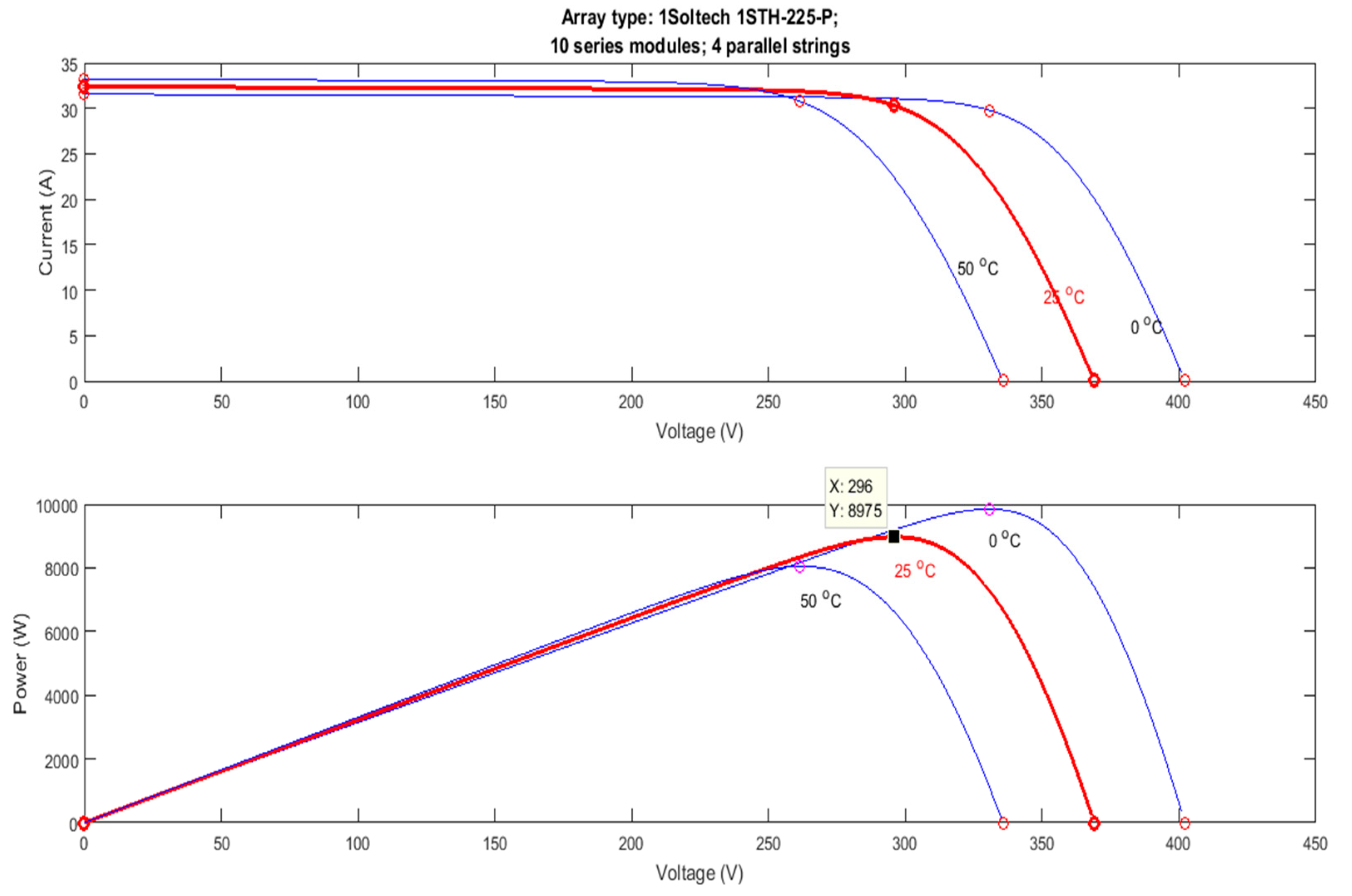
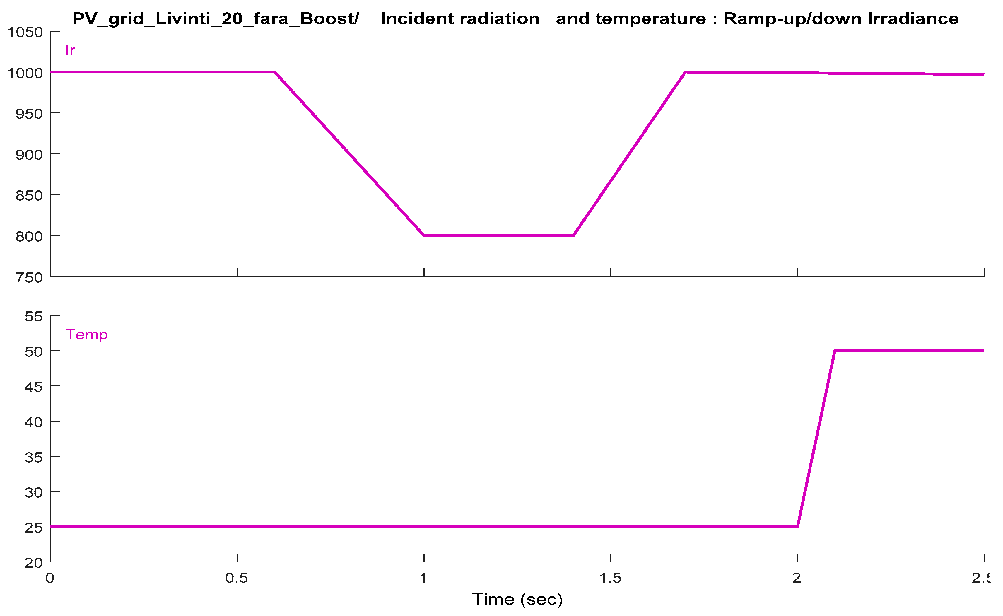
A photovoltaic module was used that was composed of 40 photovoltaic panels of Soltech 1STH-225-P. Four groups formed by 10 photovoltaic panels each, series connected, were connected in parallel. The technical characteristics of a photovoltaic panel are: P m a x = 224.36 W, U m a x = 36.9 V. The characteristics of the photovoltaic module at an intensity of the incident solar radiation of 1000 W / m 2   and a temperature of 25 (results from Figure 2): U m a x = 296 V, P m a x   = 8975 W. For the source of the solar radiation incident on the photovoltaic panels and temperature—the characteristics of variations shown in Figure 3 are imposed, for a time interval of a simulation equal to 2.5 s. The three-phase inverter is composed of power transistors of the Insulated Gate Bipolar Transistors (IGBT) type with protection diodes. The three-phase filter RL has the role of reducing the harmonics of the phase voltages. The values of the components of this filter are: L = 9.2 mH, R = 0.920 Ω. The measuring blocks are used for measuring the values of the voltages and current intensities of the three-phase grid at the output of the RL filter and of the AC grid to which the photovoltaic module is connected. The AC grid has the following parameters: U = 380 V, frequency f = 50 Hz, apparent power S = 10 MVA. The control subsystem was designed separately for the proportional- integrative (PI) controller and the fuzzy logic controller, respectively. Essentially, two distinct programs were elaborated in a MATLAB—–Simulink programming environment.

2.3. Presentation of the Control Subsystem with PI Controller

The control subsystem with PI controller is composed of the following blocks: (a) measuring block of the photovoltaic module parameters, as shown in Figure 4. The parameters of the electric energy supplied by the photovoltaic module are measured: voltage V _ P V _ and current intensity I _ P V . The electric power at the output from the photovoltaic module is calculated through the relation:
P P V = V _ P V I _ P V kW
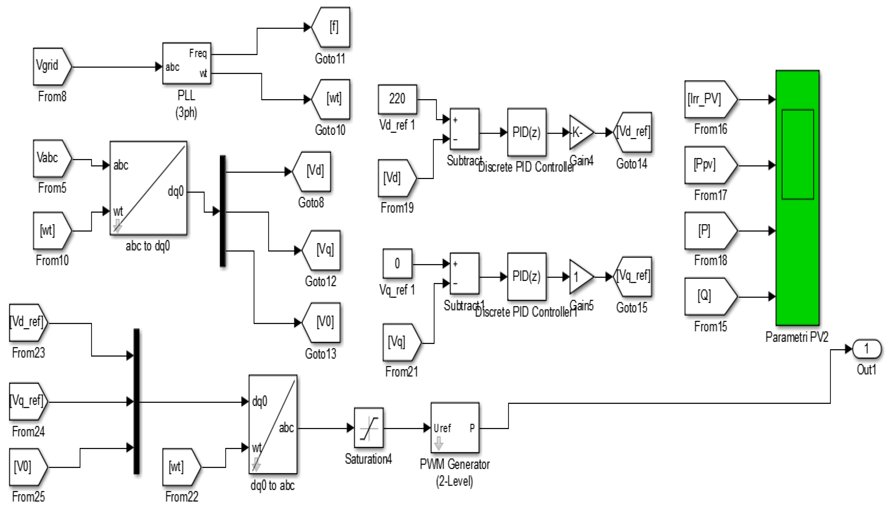
(b) The control block of the three-phase inverter is presented in Figure 5. The signal Vgrid from the measure block 2—the voltage of the three-phase grid is applied at the input of the phase lock loop (PLL) block. The PLL block will generate the three-phase signal of frequencies wt. The signal V a b c in measure block 1 will be applied at the input of the block “abc to dq0” along with the frequency signal wt. The block “abc to dq0” transforms the voltage signals from the three-phase system in the two-phase system and will supply the signals V d , V q , and V 0 . The values of these signals are given by Equation (5) [20].
[ V d V q V 0 ] = 2 3 [ cos ( w t ) cos ( w t 2 π 3 ) cos ( w t + 2 π 3 ) sin ( w t ) sin ( w t 2 π 3 ) sin ( w t + 2 π 3 ) 1 2 1 2 1 2 ]   [ V a V b V c ]
If the amplitude of the phase voltage in the AC three-phase grid is equal to 220 V, at the moment t = 0 will result in the value of the voltage component by the axis d, equal to 220 V. This value will be imposed for the reference voltage in the voltage adjustment loop by the axis d. The components V d and V q of the voltage are adjusted through the discrete PID controllers. For the component V d , the reference value V d r e f 1 = 220   V is imposed, and for the component V q , the reference value V q _ r e f 1 = 0 is imposed. The parameters of the PID controllers have the following values: k r = 0.5 , k i = 120 . The output signals from the voltage adjustment loops are applied at the input of the block “dq0 to abc ” together with the voltage signal V 0 by means of a multiplexor block. At the input of the block “dq0 to abc ”, the frequency signal wt is applied as well. The block ”dq0 to abc ” transforms the voltage signals of the two-phase system to the three-phase system and supplies the signals for controlling the PWM generator (2-level). The values of these signals are given by the equation (6), [20].
[ V a V b V c ] = 2 3 [ cos ( w t ) sin ( w t ) 1 cos ( w t 2 π 3 ) sin ( w t 2 π 3 ) 1 cos ( w t 2 π 3 ) sin ( w t + 2 π 3 ) 1 ]   [ V d V q V 0 ]
The PWM generator block will generate the control signals of the power transistors of type IGBT in the structure of the three-phase inverter. The output voltage of the inverter must have the same amplitude and phase as the voltage of the AC grid.
(c) The power measure block of the three-phase system uses the signals V a b c and I a b c supplied by the measure 1 block. With the help of the block “Power (3 ph, Instantaneous)” the active power P can be calculated, as well as the reactive power Q; Figure 6. The variation of the powers P _ P V , P,P, QQ is represented graphically in function of the variation of the solar radiation intensity and temperature during the simulation process.

2.4. Presentation of the Control Subsystem with Fuzzy Logic Controller

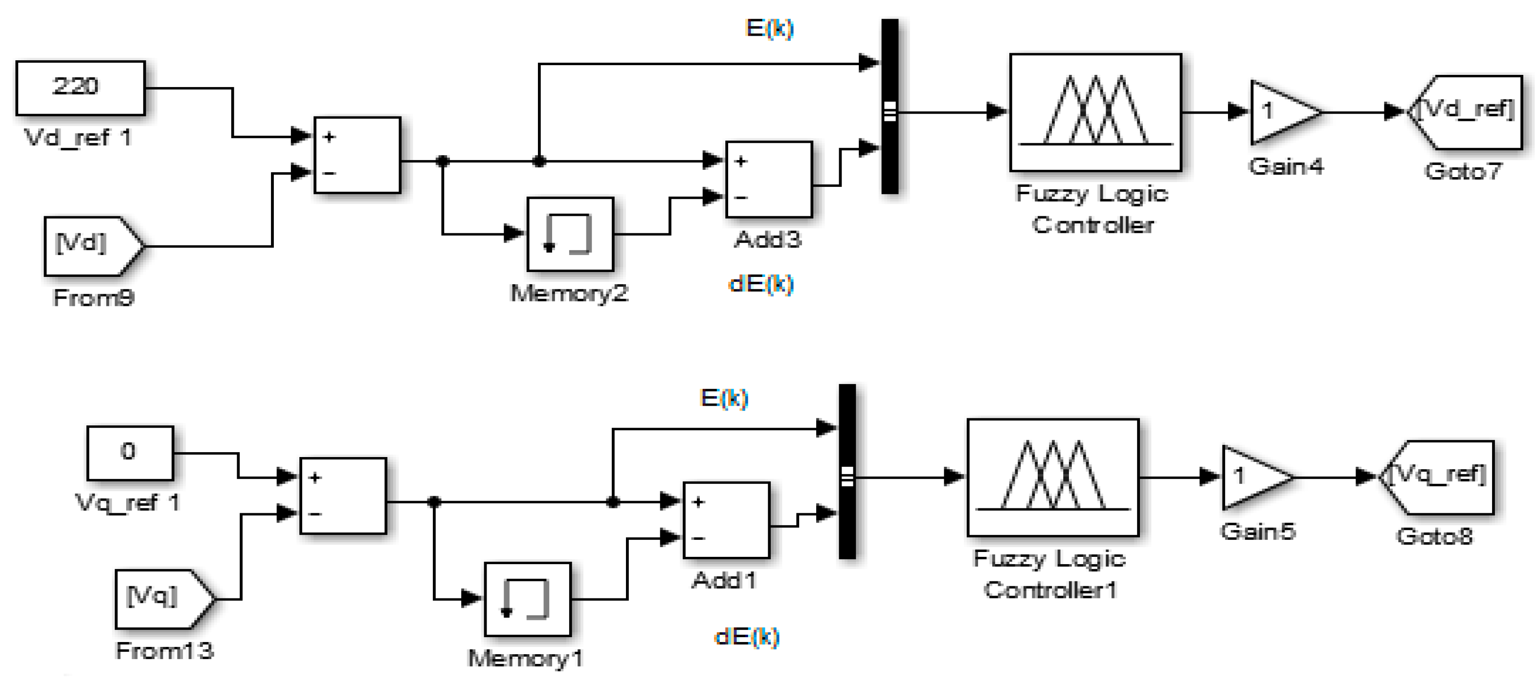
Within this subsystem, the discrete PID type controllers in the previous subsystem are replaced with fuzzy logic controllers. The structure of the adjustment loops of the voltage components V d and V q is presented at Figure 7. The other blocks remain unchanged. The error signal for the adjustment loop of the component V d is calculated through the Equation (7):
  E ( k ) d = V d _ r e f 1 V d
The error signal for the adjustment loop of the component V q is calculated through the Equation (8):
  E ( k ) q = V q _ ref 1 V q

Design of the Fuzzy Logic Controller

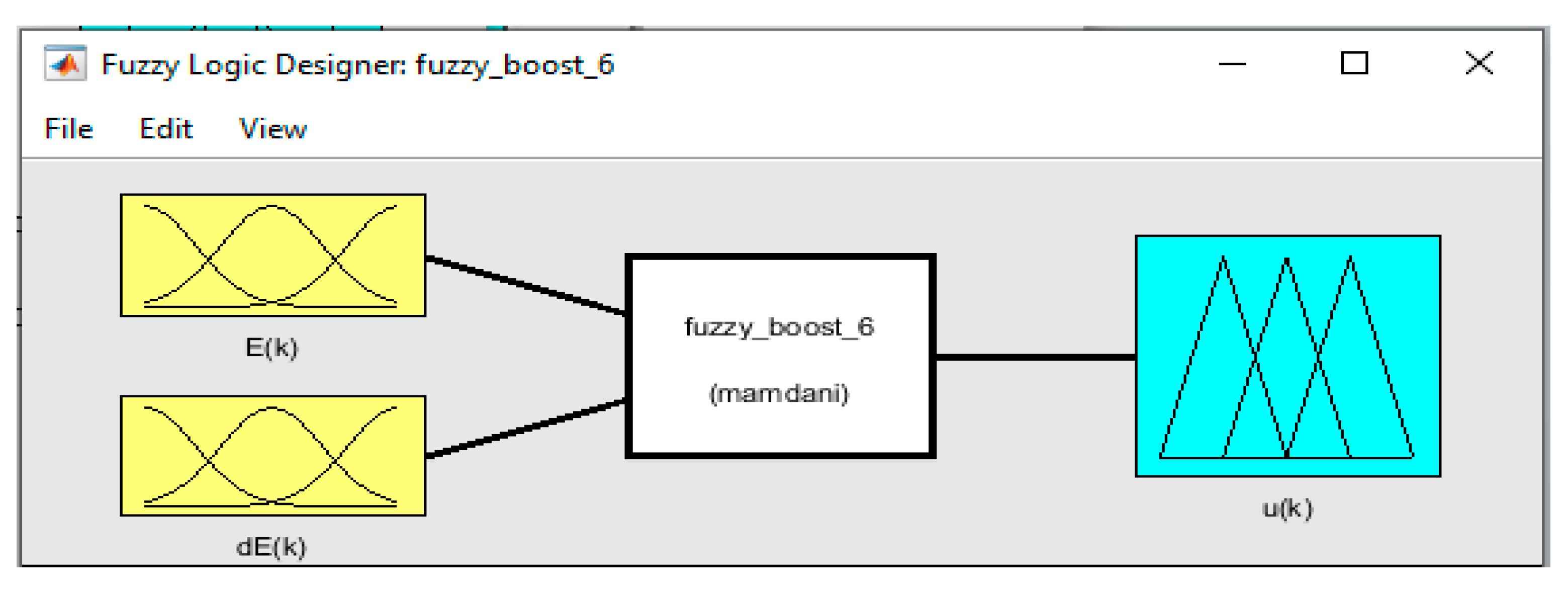
For designing the fuzzy logic controller, the input values are to be chosen: error E ( k ) and error derivate d E ( k ) , as well as the output variable u ( k ) related to each component of the voltage by the d and q axes. The structure of the fuzzy logic controller is shown in Figure 8.
For designing the fuzzy logic controller, it is not necessary to establish the mathematical model of the fix part. The variation domains of the input variables and of the output variable will be chosen and the basis of rules will be established. The output variable is determined through the de-fuzzy method of the gravity center. The variation domains of the input variables are presented in Figure 9. The variation domain of the output variable is presented in Figure 10.
The basis of rules will be done as per Table 1. The following operators will be used: if, and, then. NB—big negative, NM—medium negative, ZE—zero, PM—medium positive, PB—big positive. Examples of rules:
  • if (E(k) is NB) and (dE(k) is NB) then (u(k) is NB);
  • if (E(k) is NM) and (dE(k) is ZE) then (u(k) is NM).
As method of inference, reference [27] maximum–minimum method was used in this case:
μ U i ( u ) = m i n ( μ C i ( E i ) ,   μ O i ( u ) ) ;   μ U ( u ) = m a x [ μ U i ( u ) ]
where: μ C i ( E i ) = m i n ( μ A i ( E ) ,   μ B i ( Δ E ) ) , and μ O i ( u ) is the function imposed through the rule R i . For de-fuzzy, the method of the gravity center was used, where the abscissa of the gravity center was determined through the equation (10), [27]:
U = 1 1 u μ U ( u ) d u 1 1 μ U ( u ) d u
The output variable u(k) will be determined with the help of the relation (10). The fuzzy logic controller can be implemented and validated on the same hardware structure as that used for implementing and validating the conventional PI controller. Essentially, the hardware structure will not modify in case of implementing and validating, in real time, the two programs issued in MATLAB–Simulink for the comparative study of the photovoltaic system connected to a three-phase grid through a three-phase inverter, and additional costs will not occur from this point of view.

3. Results and Discussions

3.1. Simulation Results for the Control Subsystem Equipped with PI Controller

The variation of voltage and current intensity in function of the radiation intensity and temperature are presented in Figure 11. The voltage variation is proportional to the intensity of the solar radiation. The voltage value will decrease along with temperature increase. The analysis of the harmonics, in case of the subsystem with the PI controller, is presented in Figure 12. The total harmonic distortion (THD) has a value equal with 4.28%. The variation of powers in function of the solar radiation and temperature is presented in Figure 13.

3.2. Simulation Results for the Control Subsystem Equipped with Fuzzy Logic Controller

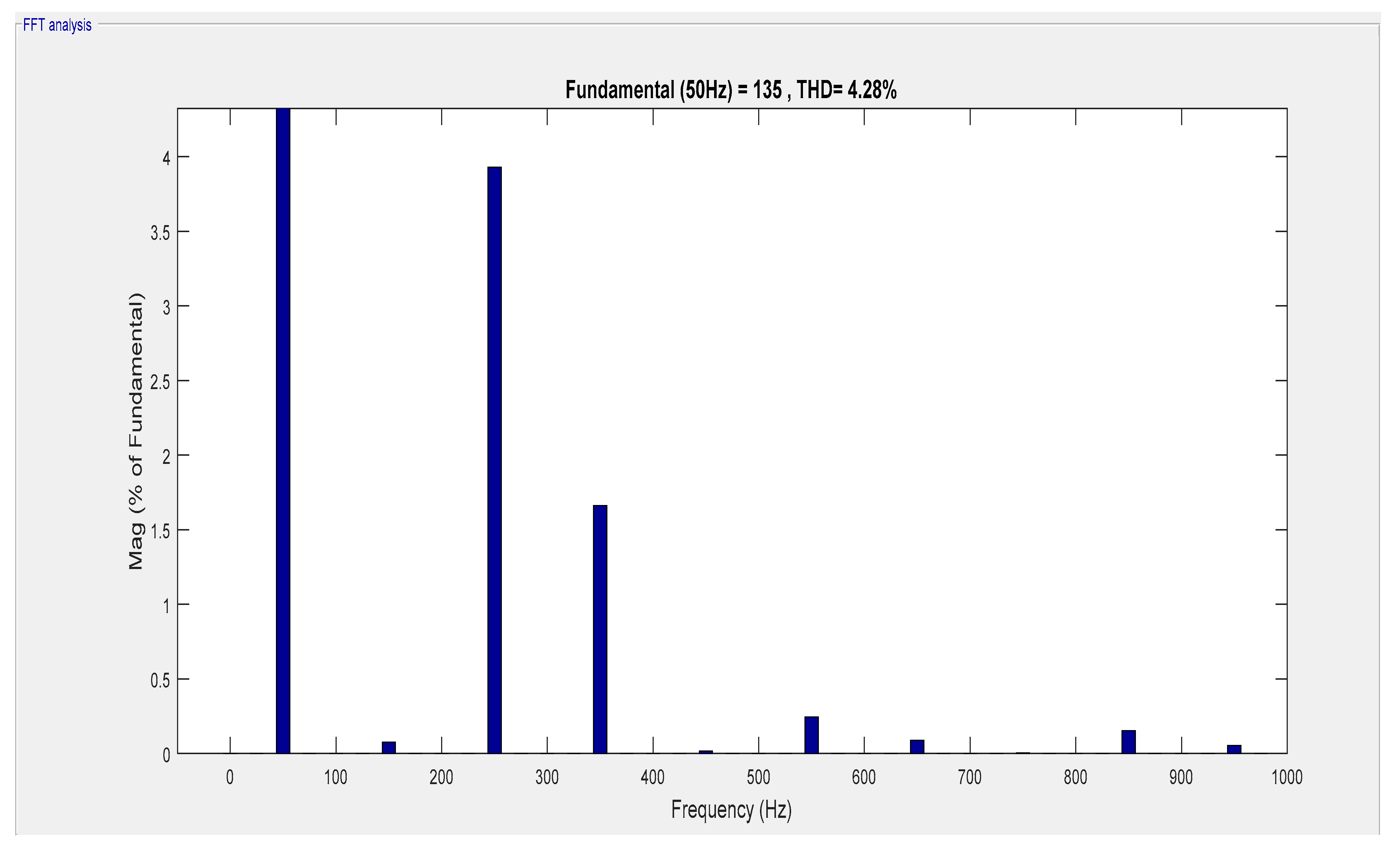
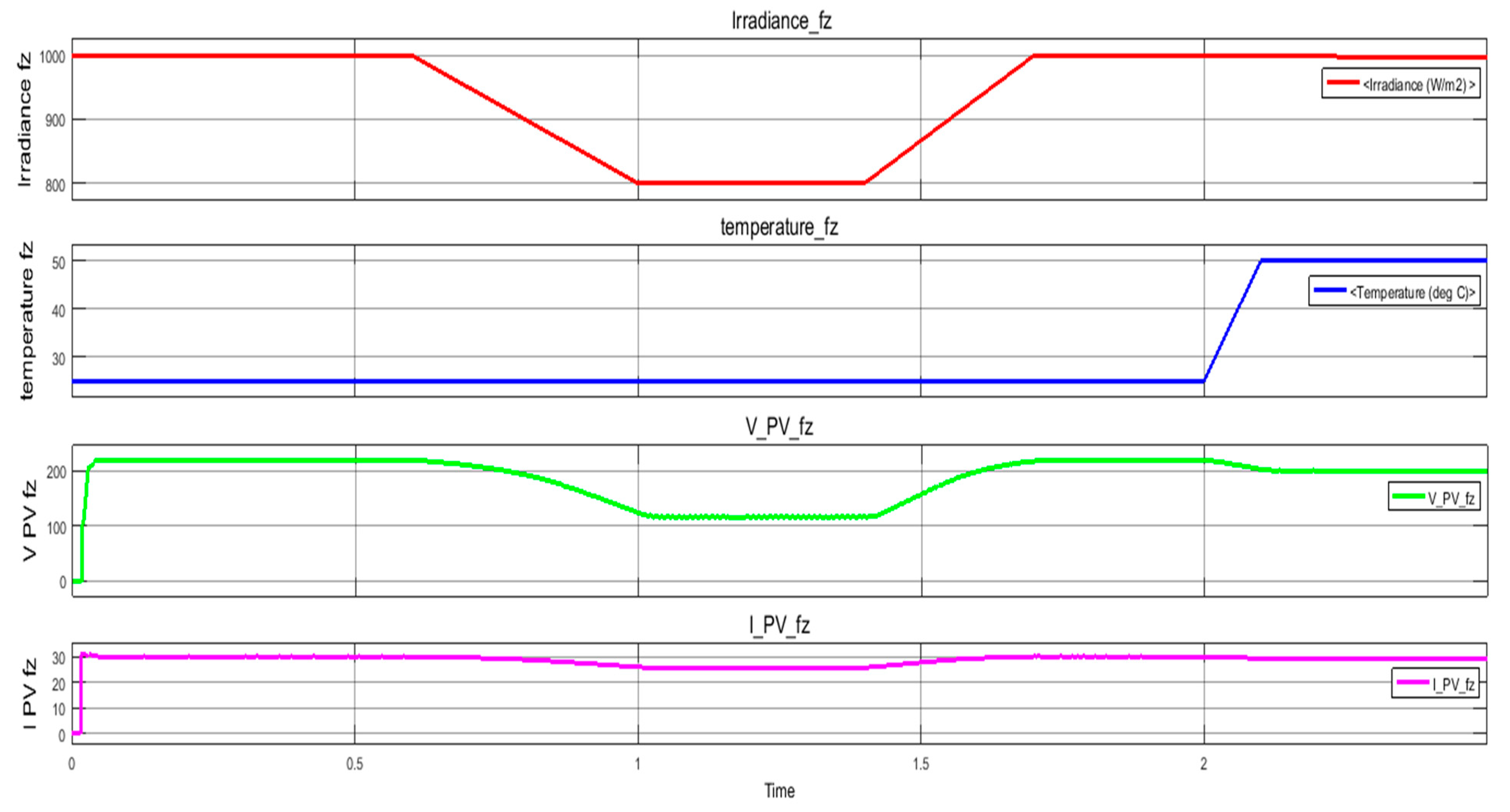
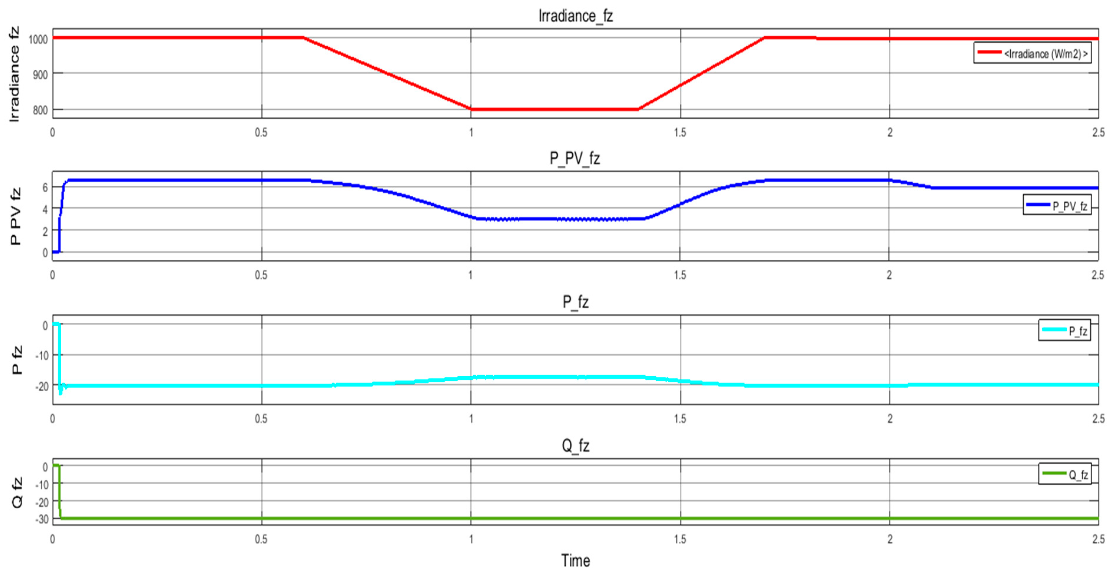
The variation of voltage and current intensity in function of the radiation intensity and temperature are presented in Figure 14. The voltage variation is proportional to the intensity of the solar radiation. The voltage value will decrease along with a temperature increase. The analysis of the harmonics, in case of the subsystem with a fuzzy logic controller, is presented in Figure 15. The total harmonic distortion (THD) has the value equal with 0.40%. The variation of powers in function of the solar radiation and temperature is presented in Figure 16.
The results obtained for the two types of controllers are presented in Table 2.
Out of the comparative analysis of the results in Table 2, it may be noticed that better performances are obtained for the control subsystem equipped with a fuzzy logic controller.

4. Conclusions

This work presents a photovoltaic system connected to an AC grid through a three-phase inverter controlled by a fuzzy logic controller or by a proportional-integral (PI) controller. The work aims to increase the quantity and quality of the electric energy produced by the photovoltaic panels and introduced to the AC grids. Two models have been elaborated in MATLAB–Simulink for the photovoltaic module composed of 40 photovoltaic panels and connected to an AC grid through a three-phase inverter. The three-phase inverter was controlled through a proportional-integrative controller or through a fuzzy logic controller. The implementation and validation in real time of the two models elaborated for the photovoltaic system, connected to a three-phase grid, can be performed on the same hardware structure. Through the usage of the fuzzy logic controller for controlling the three-phase inverter, instead of the conventional PI controller, additional costs will not occur. For designing the fuzzy logic controller—the mathematical model of the fixed part to be determined is not necessary. Out of the comparative analysis of the results, it was discovered that, through the use of the fuzzy logic controller for controlling the three-phase inverter, a higher electric power is transferred to the AC grid, compared to the case of using the PI type controller and the total harmonic distortion (THD) of the voltage, resulting after the filtering circuit has a lower value, than in case of using the PI type controller. Through the usage of fuzzy logic controllers for controlling the three-phase inverters, the efficiency of the photovoltaic systems will be increased and this will lead to lowering the costs of electric energy in the future.

Funding

This research received no external funding.

Institutional Review Board Statement

Not applicable.

Informed Consent Statement

Not applicable.

Conflicts of Interest

The author declares no conflict of interest.

References

  1. Swain, N.; Panigrahi, C.K.; Ali, S.M. Application of PI and MPPT Controller to DC-DC Converter for Constant Voltage & Power Application. IOSR J. Electr. Electron. Eng. 2016, 11, 8–15. [Google Scholar]
  2. Raj, A.; Gopinath, A. Proportional plus Integral (PI) Control for Maximum Power Point Tracking in Photovoltaic Systems. Int. Res. J. Eng. Technol. 2015, 2, 408–412. [Google Scholar]
  3. Oshaba, A.S.; Ali, E.S.; Elazim, S.M.A. PI controller design for MPPT of photovoltaic system supplying SRM via BAT search algorithm. Neural Comput. Appl. 2017, 28, 651–667. [Google Scholar] [CrossRef]
  4. Sanjeevikumar, P.; Grandi, G.; Wheeler, P.W.; Blaabjerg, F.; Loncarski, J. A Simple MPPT Algorithm for Novel PV Power Generation System by High Output Voltage DC-DC Boost Converter. In Proceedings of the IEEE 24th International Symposium on Industrial Electronics (ISIE), Rio de Janeiro, Brazil, 3–5 June 2015. [Google Scholar]
  5. Rajavel, A.; Rathina Prabha, N. Fuzzy logic controller-based boost and buck-boost converter for maximum power point tracking in solar system. Res. Artic. 2020. [Google Scholar] [CrossRef]
  6. Mahalakshmi, R.; Aswin Kumar, A.; Kumar, A. Design of Fuzzy Logic Based Maximum Power Point Tracking Controller for Solar Array for Cloudy Weather Conditions. In Proceedings of the Power and Energy Systems: Towards Sustainable Energy (PESTSE 2014), Bangalore, INDIA, 13–15 March 2014. [Google Scholar]
  7. Ozdemir, S.; Altin, N.; Sefa, I. Fuzzy logic based MPPT controller for high conversion ratio quadratic boost converter. Int. J. Hydrog. Energy 2017, 42, 17748–17759. [Google Scholar] [CrossRef]
  8. Saleh, A.; Azmi, K.S.F.; Hardianto, T.; Hadi, W. Comparison of MPPT Fuzzy Logic Controller Based on Perturb and Observe (P&O) and Incremental Conductance (InC) Algorithm on Buck-Boost Converter. In Proceedings of the 2nd International Conference on Electrical Engineering and Informatics (ICon EEI), Batam, Indonesia, 16–17 October 2018. [Google Scholar]
  9. Bounechbaa, H.; Bouzida, A.; Nabtib, K.; Benallab, H. Comparison of perturb & observe and fuzzy logic in maximum power point tracker for PV systems. Energy Procedia 2014, 50, 677–684. [Google Scholar]
  10. Yilmaz, U.; Kircay, A.; Borekci, S. PV system fuzzy logic MPPT method and PI control as a charge controller. Renew. Sustain. Energy Rev. 2018, 81, 994–1001. [Google Scholar] [CrossRef]
  11. Borni, A.; Abdelkrim, T.; Bouarroudj, N.; Bouchakour, A.; Zaghba, L.; Lakhdari, A.; Zarour, L. Optimized MPPT Controllers Using GA for Grid Connected Photovoltaic Systems. In Proceedings of the Comparative study, International Conference on Technologies and Materials for Renewable Energy, Environment and Sustainability (TMREES17), Beirut, Lebanon, 21–24 April 2017. [Google Scholar]
  12. Otmane, H.; Youssef, M.; Mokhtar, B. Comparative analysis of cascaded Fuzzy-PI controllers based-MPPT and perturb and observe MPPT in a grid-connected PV system operating under different weather and loading conditions. Int. J. Power Electron. Drive Syst. 2019, 10, 1986–1994. [Google Scholar] [CrossRef]
  13. Basaran, K.; Cetin, N.S. Designing of a fuzzy controller for grid connected photovoltaic system’s converter and comparing with PI controller. In Proceedings of the 5th International Conference on Renewable Energy Research and Applications, Birminghan, UK, 20–23 November 2016; pp. 102–106. [Google Scholar]
  14. Mosalam, H.A.; Amer, R.A.; Morsy, G.A. Fuzzy logic control for a grid-connected PV array through Z-source-inverter using maximum constant boost control method. Ain Shams Eng. J. 2018, 9, 2931–2941. [Google Scholar] [CrossRef]
  15. Shenoy1, K.L.; Nayak, C.G.; Mandi, R.P. Fuzzy Controller Based Grid Integration of Hybrid Solar Photovoltaic and DFIG Wind Energy System to Improve Power Quality. Appl. Math. Inform. Sci. 2019, 13, 447–457. [Google Scholar]
  16. Hemanand, T.; Subramaniam, N.P.; Venkateshkumar, M. Comparative analysis of intelligent controller based microgrid integration of hybrid PV/wind power system. J. Ambient Intell. Humaniz. Comput. 2018. [Google Scholar] [CrossRef]
  17. Naick, B.K.; Chatterjee, T.K.; Chatterjee, K. Fuzzy Logic Controller based PV System Connected in Standalone and Grid Connected Mode of Operation with Variation of Load. Int. J. Renew. Energy Res. 2017, 7, 311–322. [Google Scholar]
  18. Thiagarajan, Y.; Sivakumaran, T.S.; Sanjeevikumar, P. Design and Simulation of FUZZY Controller for a Grid connected Stand Alone PV System. In Proceedings of the 2008 International Conference on Computing, Communication and Networking, Karur, Tamil Nadu, India, 18–20 December 2008. [Google Scholar]
  19. Lamas, W.Q.; Tani, H.M.; Reis, L.O.M.; Ribeiro, A.C. Fuzzy Logic Control Applied To A Photovoltaic System Connected to City Network For Residential Use. Eng. Térmica (Therm. Eng.) 2008, 7, 21–26. [Google Scholar]
  20. Mutlag, A.H.; Shareef, H.; Mohamed, A.; Hannan, M.A.; Ali, J.A. An Improved Fuzzy Logic Controller Design for PV Inverters Utilizing Differential Search Optimization. Int. J. Photoenergy 2014, 2014, 469313. [Google Scholar] [CrossRef] [Green Version]
  21. Hamzaouia, I.; Bouchafaaa, F.; Hadjammara, A. Investigation of the behavior of a threephasegrid connected photovoltaic system to control active and reactive power with DPC. Energy Procedia 2011, 6, 493–502. [Google Scholar] [CrossRef] [Green Version]
  22. Ternifi, T.; Bachir, G.; Aillerie, M. A single-phase photovoltaic Microinverter topology based on boost converter. Przegląd Elektrotechniczny 2019, 95, 215–217. [Google Scholar] [CrossRef]
  23. Zheng, Z.; Zhang, T.; Xue, J. Application of Fuzzy Control in a Photovoltaic Grid-Connected Inverter. J. Electr. Comput. Eng. 2018, 2018, 3806372. [Google Scholar] [CrossRef] [Green Version]
  24. Idoniboyeobu, D.C.; Orike, S.; Biragbara, P.B. Optimization of a Grid Connected Photovoltaic System using Fuzzy Logic Control. Eur. J. Electr. Eng. Comput. Sci. 2017, 1, 4–13. [Google Scholar] [CrossRef] [Green Version]
  25. Bakhoda, O.Z.; Menhaj, M.B.; Gharehpetian, G.B. MPPT for a three-phase grid- connected PV system (Fuzzy Logic Controller vs. PI Controller. In Proceedings of the 4th Iranian Joint Congress on Fuzzy and Intelligent Systems (CFIS), Zahedan, Iran, 9–11 September 2015. [Google Scholar]
  26. Daniel, S.A.; Ammasai, G.N. A Novel Hybrid Isolated Generating System Based on PV Fed Inverter-Assisted Wind-Driven Inductio Generators. IEEE Trans. Energy Convers. 2004, 19, 416–422. [Google Scholar] [CrossRef]
  27. Sofron, E.; Bizon, N.; Ionita, S.; Raducu, R. Sisteme de Control Fuzzy—Modelare si Proiectare Asistate de Calculator. Available online: http://cacheprod.bcub.ro/webopac/FullBBBody.csp?SearchMethod=Find_1&Profile=Default&OpacLanguage=rum&RequestId=110079_1&RecordNumber=0&JavaScriptDisabled=1&CSPCHD=01910000000148eah60v000500085894 (accessed on 26 February 2021).
Figure 1. Block diagram of the model for the photovoltaic system connected to an AC grid.
Sustainability 13 02562 g001
Figure 2. Characteristics of the photovoltaic system.
Sustainability 13 02562 g002
Figure 3. Variation of the intensity of the incident solar radiation and environment temperature.
Sustainability 13 02562 g003
Figure 4. Measure block of the photovoltaic module parameters.
Sustainability 13 02562 g004
Figure 5. The control block of the three—-phase inverter.
Sustainability 13 02562 g005
Figure 6. Calculation block of the three-phase system powers.
Sustainability 13 02562 g006
Figure 7. Structure of the adjustment loops with fuzzy logic controllers.
Sustainability 13 02562 g007
Figure 8. Structure of the fuzzy logic controller.
Sustainability 13 02562 g008
Figure 9. Variation domains of the input variables.
Sustainability 13 02562 g009
Figure 10. Variation domain of the output variable.
Sustainability 13 02562 g010
Figure 11. Variation of voltage and current intensity in function of the solar radiation and temperature in case of the subsystem with the proportional-integral (PI) controller.
Sustainability 13 02562 g011
Figure 12. Analysis of the harmonics in case of the subsystem with the PI controller.
Sustainability 13 02562 g012
Figure 13. Variation of powers in function of the solar radiation in case of the subsystem with the PI controller.
Sustainability 13 02562 g013
Figure 14. Variation of voltage and current intensity in function of the solar radiation and temperature in case of the subsystem with a fuzzy logic controller.
Sustainability 13 02562 g014
Figure 15. Analysis of the harmonics in case of the subsystem with a fuzzy logic controller.
Sustainability 13 02562 g015
Figure 16. Variation of powers in function of the solar radiation in case of the subsystem with a fuzzy logic controller.
Sustainability 13 02562 g016
Table 1. The basis of rules.
E(k)
NBNMZEPMPB
dE(k)NBNBNBNBNMZE
NMNBNBNMZEPM
ZENBNMZEPMPB
PMNMZEPMPBPB
PBZEPMPBPBPB
Table 2. The results obtained.
Solar Radiation Intensity
Parameter
1000 W/m2
At 25 °C
800 W/m2
At 25 °C
1000 W/m2
At 50 °C
Voltage V_PV_pi (Figure 11)165145150
Current I_PV_pi (Figure 11)302629
Power P_PV_pi (Figure 13)4.63.54.3
Voltage V_PV_fz (Figure 14)220125200
Current I_PV_fz (Figure 14)302729
Power P_PV_fz (Figure 16) 6.53.16
Publisher’s Note: MDPI stays neutral with regard to jurisdictional claims in published maps and institutional affiliations.