Review

Future Options for Lightweight Photovoltaic Modules in Electrical Passenger Cars

1
Department of Electrical and Computer Engineering, Sungkyunkwan University, Suwon 16419, Korea
2
Department of Economics Program Director Logistic & Air Traffic Management, Anhalt of University of Applied Science, 06406 Bernburg, Germany
3
KEPCO International Nuclear Graduate School, Ulsan 45014, Korea
*
Authors to whom correspondence should be addressed.
Sustainability 2021, 13(5), 2532; https://doi.org/10.3390/su13052532
Submission received: 22 January 2021 / Revised: 14 February 2021 / Accepted: 20 February 2021 / Published: 26 February 2021

Abstract

:
Twenty-three percent of carbon emissions come from fossil fuels used in transportation. Electric vehicles are suggested as alternatives to fossil-fueled vehicles. Cars having vehicle integrated photovoltaics (VIPV) on the roof have recently been launched, aiming to increase fuel efficiency and increase maximum mileage by supplying electricity to the vehicle when needed. VIPV needs to be light in terms of efficiency. The use of polymeric materials, made of low-iron tempered glass on the front that contributes significantly to the module’s weight, is required instead. The use of a sandwich structure with polymer material achieves nine times stiffer rigidity than an aluminum sheet of the same weight. It can be used with a weight that is half that of glass through the lightweight and light-transmitting polymer material on the front side. The concentrator photovoltaic module structure is used to compensate for various angles of incidence on a moving car, and it is advantageous because it is easy to apply and has a low weight owing to its excellent flexibility. It is possible to reduce the weight from 20 kg to less than 10 kg by limiting the use of glass.

1. Introduction

Significant efforts have been made to preserve the environment worldwide. Researchers have tried to reduce greenhouse gases (GHG) that cause global warming and climate climate anomalies. Many countries have signed agreements, such as the Kyoto Protocol and the Paris Climate Agreement, to reduce carbon dioxide emissions, which account for 77% of GHG [1]. The Paris Climate Agreement aimed to reduce carbon emissions by 37% by 2030. Transportation accounts for 23% of the world’s CO2 emissions, mostly from fossil fuel combustion [2]. The root cause of carbon emissions from transportation is an increase in vehicle use, population, and gross domestic product (GDP) per capita [3].
The vehicles’ fuel consumption has been reduced by improving their efficiency by means such as reducing the weight of vehicles and improving engine performance. However, this is not an effective way to reduce CO2 emissions. As a fundamental measure, the use of electric vehicles, not fossil fuel vehicles, should be emphasized. Electric vehicles use electric energy for power and do not emit pollutants. The disadvantage of electric vehicles is that the refueling (charging) time is comparably longer than that of fossil fuel vehicles. A fossil fuel vehicle takes up to 5 min to refuel, but an electric vehicle can take up to 30 min to recharge 80% of the battery capacity under normal charging conditions [4]. The use of photovoltaic modules helps alleviate the battery capacity constraints in electric vehicles and will increase the electricity consumption efficiency in the future. As a solar module directly produces electricity using the photoelectric effect of silicon, unlike other renewable energy sources, it does not need a mechanical motor. This makes it suitable for automobiles because the solar module does not generate noise and vibration during power generation, is simple to install and is inexpensive [5]. A photovoltaic module can installed on the roof of a vehicle and can be charged simply by exposing the module to sunlight.
Cars that include solar modules are expected to be released soon in the market. Cars with photovoltaic-equipped solar roofs include the Hyundai Motors Sonata model and the Toyota Prius model. In 2014, a concept design using solar and wind power was introduced by Mercedes-Benz, and the Dutch Lightyear concept car was capable of driving 400–800 km through solar charging with the goal of launch in 2021 [6]. Australia’s EVX venture aims to drive up to 400 km on cloudy days or nights, while Hanergy in China is launching a concept car with a goal of six hours’ driving time. Concept cars are appearing, and a model that is actually a solar-roof-type module applied to a passenger car as an option is also available [7].
Figure 1 shows the Hyundai Motors’ Sonata model, which is not designed to install additional modules on the vehicle roof. As it performs the role of the roof simultaneously with power generation, the use of the module does not cause air resistance and design problems. Solar roofs provide fuel efficiency improvement and auxiliary power source. When installing a solar module, it should be lightweight because increasing the weight reduces the fuel efficiency of the car. It may be installed only on the roof but can also be installed on the bonnet or the side of the vehicle in the future [8].

2. Effects of Applying Solar Modules to Passenger Cars

Currently-released car models with solar roofs include the Toyota’s Prius with a 180 W module and Hyundai Sonata with a 210 W module. When charging for 5 h, the maximum amount of energy that can be obtained by using the module during a day is 1 kWh. However, the energy production from the PV module depends on many factors, i.e., location (latitude), temperature of the module, tilt angle, shading (in the cities).
Figure 2 shows a graph of the module efficiency and the area according to the fuel efficiency of an electric vehicle. As the weight of the vehicle gradually becomes lighter, the area of the module for driving a day with the solar module decreases. With 20 percent of the modules, a 600 kg car would need an area of 3.8 m2 whereas a 1410 kg car would need an area of 8 m2. Today’s electric vehicles can move approximately 6 km on average with 1 kWh of electricity. If the weight of an electric vehicle can be reduced from 1410 to 600 kg, it can travel 17 km with 1 kWh of energy [10]. When 2 kWh of energy is generated, a 600 kg car can drive 34 km. In order to get 2 kWh of energy per day, a module of 800 W must be installed in the vehicle. The area for installing the 800 W module is 3.6 m2, which is more than 2.5 m2 combined with the roof and hood, so it needs to be installed on the side of the vehicle [11]. If you include the side of the vehicle, it is 4.5 m2.
The average driving distance in Korea is 38.5 km, and the average daily drive distance of urban drivers in Japan is 24 km. In Germany, the average mileage per year is 14,000 km, which means that a car travels about 38 km per day [8,12,13,14]. This means that with solar modules, city drivers do not need to recharge.
Because electric vehicles do not have an engine, the most common method is to reduce the weight of the vehicle as a method to improve fuel economy, except for aerodynamic design and battery efficiency. Commercial silicon-based modules weigh 20 kg, and lightweight modules weigh approximately 10 kg [15]. The weight of the panoramic sunroof used on the roof of a passenger car is 60–80 kg, and the solar module used for the Prius is approximately 30 kg. By contrast, reducing the weight of a fossil-fueled passenger car by 10 kg would improve fuel economy by 2.8% [16]. In the case of an electric vehicle, it is expected that it will reach 10 km/kWh if the weight becomes lighter by 400 kg.

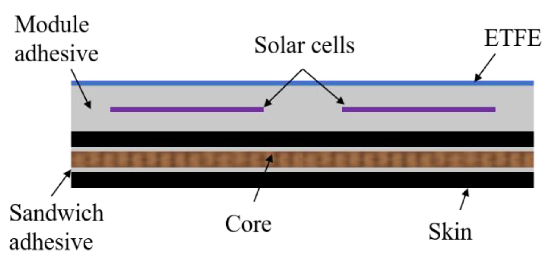
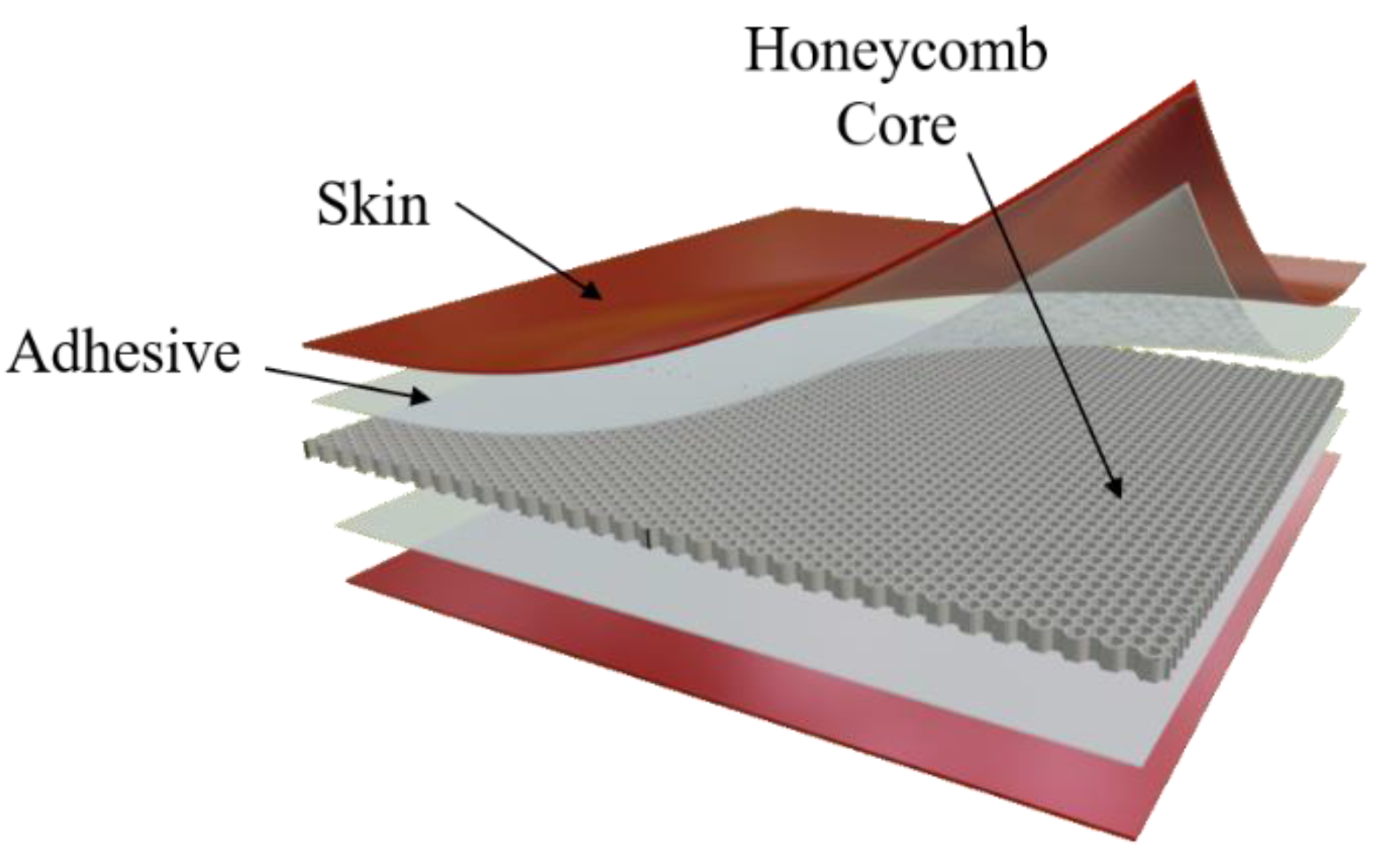
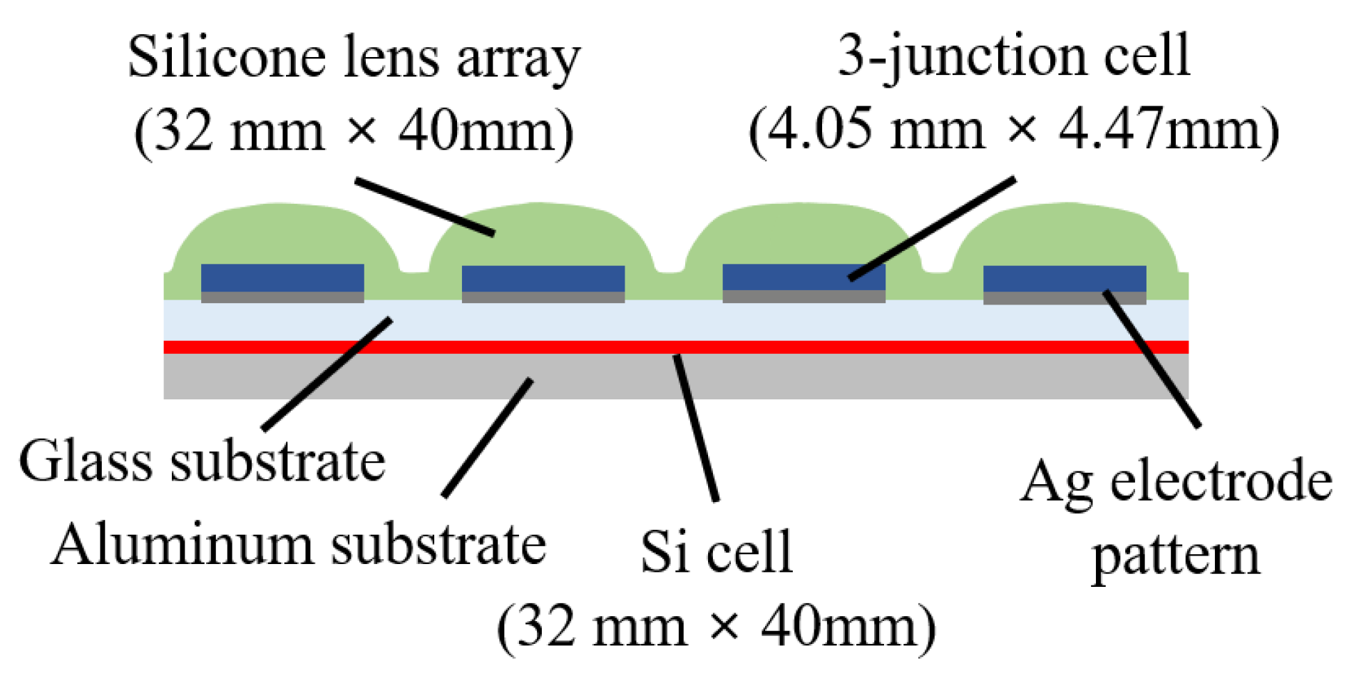
3. Methods of Reducing the Weight of Solar Modules for Passenger Cars

The weight of the solar module for a passenger car is important because it is related to the fuel economy of the car. The roof shape of the passenger car is not flat and is aerodynamically curved. Figure 3 shows the area and curvature of the passenger car roof [17]. The flat roof area of the passenger car is 2 m2, which is not wide, and the applicable area can be installed with a module of 200 W standard [18].
The general structure of a silicon-based module is shown in Figure 4. Low-iron tempered glass is used on the front of the solar cell to protect the solar cell and transmit as much light as possible. Ethylene vinyl acetate (EVA) and Tedlar polyester were used as the laminating material, and aluminum was used as the frame [19]. However, PV modules integrated into passenger cars must be light and flexible for better performance. The glass accounts for half of the solar module weight. Modules for photovoltaic mounted vehicles mainly used transparent plastic materials or glass fiber reinforced polymer composite materials instead of the tempered glass [20].
Materials used to replace glass are polycarbonate (PC) and polymethyl methacrylate (PMMA). Table 1 shows the density and thermal conductivity properties of glass, PMMA, and PC. PMMA and PC have a density half that of glass, which can significantly reduce the weight of the module.
Because its thermal conductivity is about 0.2 W/mk, which islower than that of glass, it is possible to minimize the influence of solar heat on the cell characteristics. A method of using a polymer protective film is also presented. The polymer protective film is 32 times lighter than glass, 16 times thinner than glass, and has high transmittance; therefore, it appears to be an effective replacement material [21]. However, this polymer protective film does not pass the international standard IEC61215. It lacks mechanical rigidity. Complementing the mechanical stiffness is a very effective way to reduce weight.
Figure 5 shows the structure using ethylene tetrafluoroethylene (ETFE) with the front glass and frame removed [22]. ETFE is a fluorine-based plastic that is widely applied in the automotive industry. ETFE offers a variety of properties, including resistance to radiation and outdoor climatic conditions, excellent electrical resistance, stiffness, and impact strength [23]. The backside uses the aluminum honeycomb core structure instead of the back sheet to ensure the rigidity of the module.
Figure 6 shows the structure of the honeycomb sandwich. The structure consists of three components: skin, core, and adhesive. The skin is attached to the core through the adhesive. The sandwich structure is similar to that of the I-shaped steel. The main difference is that the core of the sandwich is made of a material different from the skin, and the stress is not concentrated in a specific area but is distributed through the skin.
Therefore, the adhesive bond between the skin and the core must be strong enough to transfer stress from one skin to another through the sandwich core without peeling. If the material is selected properly, it can be made almost 37 times stiffer and more than nine times stronger than conventional aluminum sheets while weighing almost the same [24]. This can be used to create a much lighter material. Instead of using ETFE, glass fiber reinforced polymer (GFRP) can be used to reduce the module weight to 5–7 kg [25]. GFRP is also based on the honeycomb core structure. Both methods have passed the IEC 61215 standard, and the module’s weight was reduced to 6 kg/m2. It is a structure for building-integrated photovoltaics (BIPV) owing to its sufficient mechanical strength, but it can be used for vehicle-integrated photovoltaics (VIPVs).
Figure 7 shows the structure of the concentrator photovoltaic (CPV) [26]. The silicon lens used on the front makes it easier to respond to the incident angle of sunlight, which is difficult to cope with in the city. In urban areas, the angle of incident light is not constant due to tall buildings and street trees. The influence of the incident light angle is corrected through the convex lens. In addition, one size is advantageous for bending and can be installed in a larger area.

4. Conclusions

This study investigated solar modules suitable for electric passenger cars. Since Korea has a relatively small land area, solar modules must be used in the form of VIPV. For this, we conducted a review on lightening the vehicle. The electric vehicles currently available have a power efficiency of 6 km/kWh, so solar modules cannot be completely exempted from the requirement for charging. However, with only 10 km/kWh, the 500 W solar module can generate a driving distance of 20 km owing to roof and hood installations. Because the average daily mileage of a car is less than 40 km, it is possible to generate enough energy to cover as much as 50% of the driven distance. To improve the fuel economy of an electric vehicle, the most obvious way is to reduce the weight. If the weight can be reduced to 600 kg, an additional fuel economy of 17 km/kWh can be obtained, freeing the driver from the burden of charging. Therefore, the weight of the solar module plays an important role.
To reduce the weight of solar modules, a method to replace the low-iron tempered glass used as a finishing material has been proposed. The method providing the most weight reduction uses the polymer film, but the IEC61215 test has not been performed, so it appears that the mechanical properties are insufficient. It is believed that if this part is supplemented, it is possible to create a module with simple yet excellent characteristics. Alternatively, CPV may be the best fit. In the case of automobiles, because it is difficult to change the incidence angle, the use of CPV minimizes the effect of the angle and enables stable power generation. In addition, it can be installed according to the shape of a curved car, so it can use a wide area, and its weight is lighter than 5 kg/m2; thus, it is possible to reduce weight. The market for electric vehicles continues to grow and so does the use of solar modules. Many cars that use solar modules are expected to be released in the future. Increased research on automotive solar modules may lead to increase in the number of cars using them.

Author Contributions

S.K. and E.C. are the main author; methodology, M.H.; validation, E.C. and J.Y.; formal analysis, S.P. and Y.Y.; writing—original draft preparation, S.K. and E.C.; writing—review and editing, E.C.; supervision, J.Y.; project administration, Y.Y.; funding acquisition, J.Y. All authors have read and agreed to the published version of the manuscript.

Funding

Korea Institute of Energy Technology Evaluation and Planning (KETEP) and the Korean Ministry of Trade, Industry and Energy (MOTIE).

Institutional Review Board Statement

Not applicable.

Informed Consent Statement

Not applicable.

Data Availability Statement

Not applicable.

Acknowledgments

This research was supported by grants from the New & Renewable Energy Technology Development Program of the Korea Institute of Energy Technology Evaluation and Planning (KETEP) funded by the Korean Ministry of Trade, Industry and Energy (MOTIE) (Project No. 20194010000090 and 20193010014850).

Conflicts of Interest

The authors declare no conflict of interest.

References

  1. Longo, M.; Yaïci, W.; Foiadelli, F. Electric vehicles charged with residential’s roof solar photovoltaic system: A case study in Ottawa. Int. Conf. Renew. Energy Res. Appl. ICRERA 2017, 2017, 121–125. [Google Scholar]
  2. Liu, Z.; Li, L.; Zhang, Y.J. Investigating the CO2 emission differences among China’s transport sectors and their influencing factors. Nat. Hazards 2015, 77, 1323–1343. [Google Scholar] [CrossRef]
  3. Lakshmanan, T.R.; Han, X. Factors underlying transportation CO2 emissions in the U.S.A.: A decomposition analysis. Transp. Res. Part D Transp. Environ. 1997, 2, 1–15. [Google Scholar] [CrossRef]
  4. Lee, Y.; Hur, J. A simultaneous approach implementing wind-powered electric vehicle charging stations for charging demand dispersion. Renew. Energy 2019, 144, 172–179. [Google Scholar] [CrossRef]
  5. Giannouli, M.; Yianoulis, P. Study on the incorporation of photovoltaic systems as an auxiliary power source for hybrid and electric vehicles. Sol. Energy 2012, 86, 441–451. [Google Scholar] [CrossRef]
  6. Petrović, N.T. The future of moto auto world. Int. Sci. J. Trans Motauto World 2020, 55, 54–55. [Google Scholar]
  7. Yamaguchi, M.; Masuda, T.; Araki, K.; Sato, D.; Lee, K.H.; Kojima, N.; Takamoto, T.; Okumura, K.; Satou, A.; Yamada, K.; et al. Development of high-efficiency and low-cost solar cells for PV-powered vehicles application. Prog. Photovolt. Res. Appl. 2020, 1–10. [Google Scholar] [CrossRef]
  8. Masuda, T.; Araki, K.; Okumura, K.; Urabe, S.; Kudo, Y.; Kimura, K.; Nakado, T.; Sato, A.; Yamaguchi, M. Static concentrator photovoltaics for automotive applications. Sol. Energy 2017, 146, 523–531. [Google Scholar] [CrossRef]
  9. Won Yang, H. Hyundai Launches First Car with Solar Roof Charging System. Available online: https://www.hyundai.news/eu/brand/hyundai-launches-first-car-with-solar-roof-charging-system/ (accessed on 15 May 2020).
  10. Araki, K.; Ji, L.; Kelly, G.; Yamaguchi, M. To do list for research and development and international standardization to achieve the goal of running a majority of electric vehicles on solar energy. Coatings 2018, 8, 251. [Google Scholar] [CrossRef] [Green Version]
  11. Yamaguchi, M.; Masuda, T.; Araki, K.; Sato, D.; Lee, K.; Kojima, N.; Takamoto, T.; Okumura, K.; Satou, A.; Yamada, K.; et al. Role of PV-Powered Vehicles in Low-Carbon Society and Some Approaches of High-Efficiency Solar Cell Modules for Cars. Energy Power Eng. 2020, 12, 375–395. [Google Scholar] [CrossRef]
  12. Jochem, P.; Babrowski, S.; Fichtner, W. Assessing CO2 emissions of electric vehicles in Germany in 2030. Transp. Res. Part A Policy Pract. 2015, 78, 68–83. [Google Scholar] [CrossRef] [Green Version]
  13. Christensen, L.; Klauenberg, J.; Kveiborg, O.; Rudolph, C. Suitability of commercial transport for a shift to electric mobility with Denmark and Germany as use cases. Res. Transp. Econ. 2017, 64, 48–60. [Google Scholar] [CrossRef] [Green Version]
  14. Reuß, M.; Grube, T.; Robinius, M.; Stolten, D. A hydrogen supply chain with spatial resolution: Comparative analysis of infrastructure technologies in Germany. Appl. Energy 2019, 247, 438–453. [Google Scholar] [CrossRef]
  15. Nussbaumer, H.; Klenk, M.; Keller, N.; Turnheer, J.; Ammann, P. Record-Light Weight c-Si Modules Based on the Small Unit Compound Approach–Mechanical Load Tests and General Results. Eur. Photovolt. Sol. Energy Conf. Exhib. 2017, 146–150. [Google Scholar] [CrossRef]
  16. Arleth, M. Trends in Lightweight Construction of Roofs. ATZ Worldw. 2015, 4, 38–43. [Google Scholar]
  17. Araki, K.; Algora, C.; Siefer, G.; Nishioka, K.; Leutz, R.; Carter, S.; Wang, S.; Askins, S.; Ji, L.; Kelly, G. Standardization of the CPV and car-roof PV technology in 2018-Where are we going to go? AIP Conf. Proc. 2018, 2012, 070001. [Google Scholar]
  18. Vu, N.H.; Pham, T.T.; Shin, S. Flat concentrator photovoltaic system for automotive applications. Sol. Energy 2019, 190, 246–254. [Google Scholar] [CrossRef]
  19. Korkut, T.B.; Goren, A.; Ezan, M.A. A CFD study on photovoltaic performance investigation of a solar racing car. In Green Energy and Technology; Dincer, I., Colpan, C.O., Ezan, M.A., Eds.; Springer International Publishing: Cham, Switzerland, 2020; pp. 509–529. [Google Scholar]
  20. Gorter, T.; Reinders, A.H.M.E. A comparison of 15 polymers for application in photovoltaic modules in PV-powered boats. Appl. Energy 2012, 92, 286–297. [Google Scholar] [CrossRef]
  21. Jong, L.; Shin, R.; Gyun, W.; Hee, Y.; Kim, S.; Sung, Y. A Study on the Output and Reliability Characteristics of Ultra Barrier Film PV Module. J. Korean Sol. Energy Soc. 2019, 39, 1–10. [Google Scholar]
  22. Martins, A.C.; Chapuis, V.; Virtuani, A.; Ballif, C. Robust Glass-Free Lightweight Photovoltaic Modules with Improved Resistance to Mechanical Loads and Impact. IEEE J. Photovolt. 2019, 9, 245–251. [Google Scholar] [CrossRef]
  23. Burton, W.S.; Noor, A.K. Structural analysis of the adhesive bond in a honeycomb core sandwich panel. Finite Elem. Anal. Des. 1997, 26, 213–227. [Google Scholar] [CrossRef]
  24. Kindinger, J. ASM HANDBOOK. Lightweight Structural Cores. 2001, pp. 180–183. Available online: https://dl.asminternational.org/handbooks/book/60/chapter-abstract/699237/Lightweight-Structural-Cores?redirectedFrom=fulltext (accessed on 15 May 2020).
  25. Martins, A.C.; Chapuis, V.; Virtuani, A.; Ballif, C. Ultra-Lightweight PV module design for Building Integrated Photovoltaics. Photovolt. Spec. Conf. 2017, 2104–2108. [Google Scholar] [CrossRef]
  26. Sato, D.; Lee, K.H.; Araki, K.; Masuda, T.; Yamaguchi, M.; Yamada, N. Design and Evaluation of Low-concentration Static III-V/Si Partial CPV Module for Car-rooftop Application. In Proceedings of the 2018 IEEE 7th World Conference on Photovoltaic Energy Conversion (WCPEC) (A Joint Conference of 45th IEEE PVSC, 28th PVSEC & 34th EU PVSEC), Waikoloa Village, HI, USA, 10–15 June 2018; pp. 954–957. [Google Scholar]
Figure 1. Design of photovoltaic mounted roof sonata of Hyundai Motors [9]. In the above, the copyright of Hyundai Motor’s photographs is not copyrighted when used for academic purposes. (https://www.hyundai.news/eu/brand/hyundai-launches-first-car-with-solar-roof-charging-system/), accessed on 25 February 2021.
Sustainability 13 02532 g001
Figure 2. Module efficiency and area according to electricity efficiency.
Sustainability 13 02532 g002
Figure 3. Passenger car roof area and curvature.
Sustainability 13 02532 g003
Figure 4. Commercial view of solar panel construction.
Sustainability 13 02532 g004
Figure 5. Sandwich honeycomb core structure with ETFE.
Sustainability 13 02532 g005
Figure 6. Sandwich structure of honeycomb core.
Sustainability 13 02532 g006
Figure 7. Concentrator photovoltaic structure0.
Sustainability 13 02532 g007
Table 1. Characteristics of materials.
MaterialsDensity (g/cm3)Thermal Conductivity (W/mk)
Glass2.550.8
PMMA1.190.167–0.25 1
PC1.20.19–0.22
Publisher’s Note: MDPI stays neutral with regard to jurisdictional claims in published maps and institutional affiliations.

