
Benefits of Non-Planar Printing Strategies Towards Eco-Efficient 3D Printing


 ,
,  and
and
Abstract
1. Introduction
2. Materials and Methods
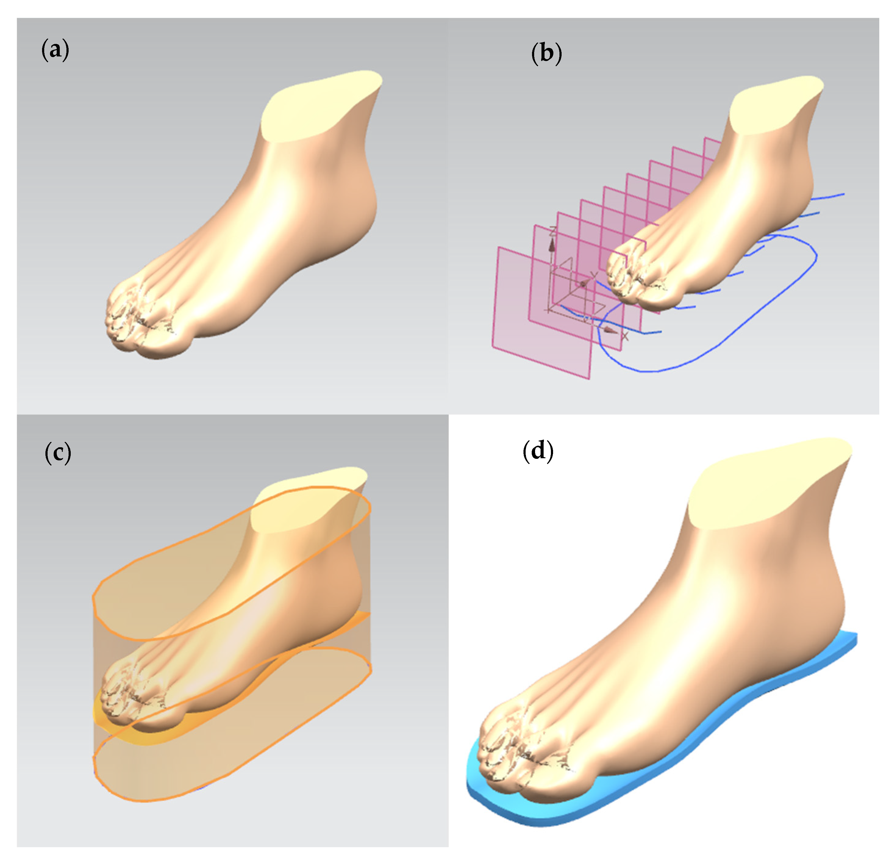
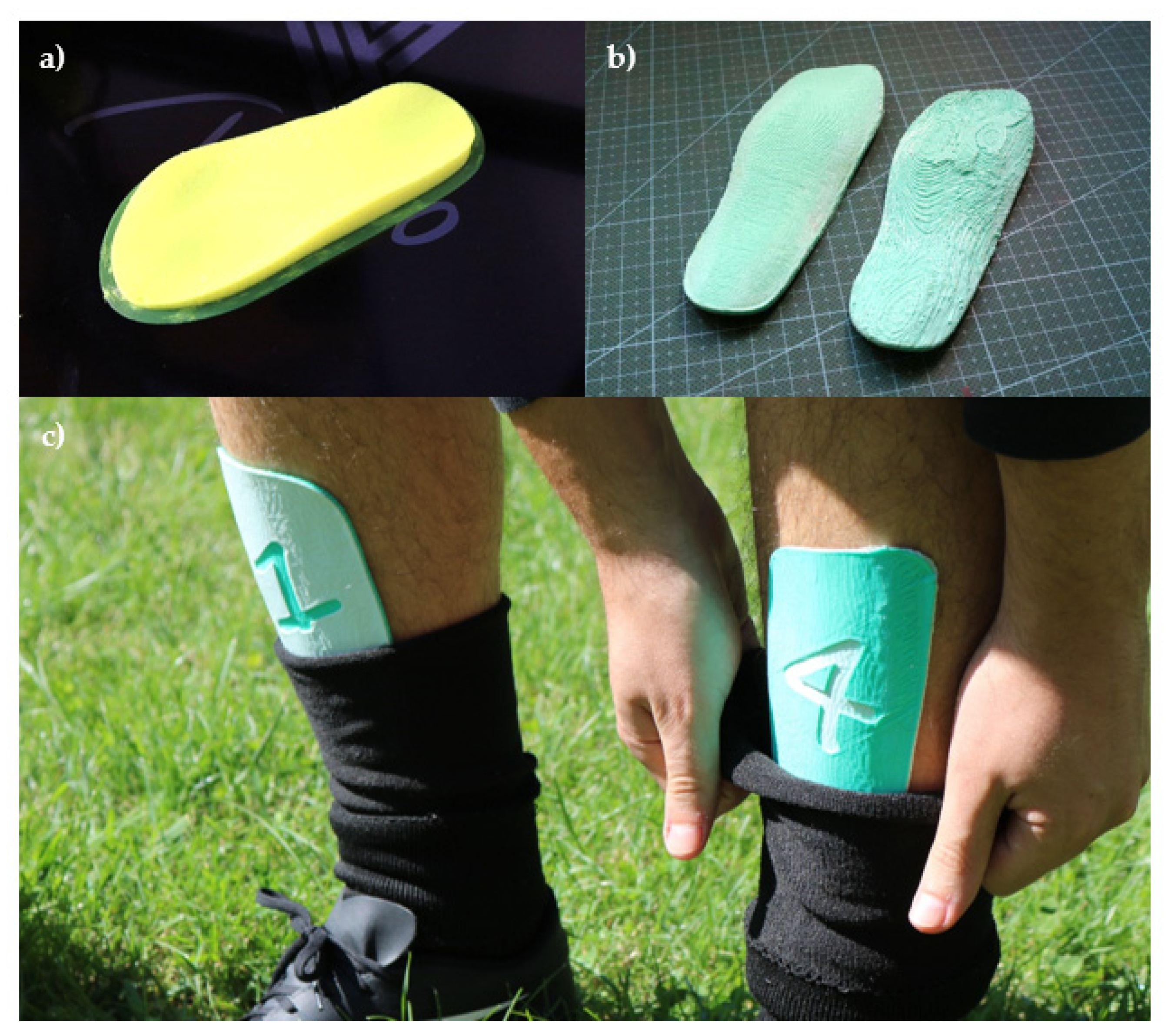
2.1. Design Software and Geometries Designed
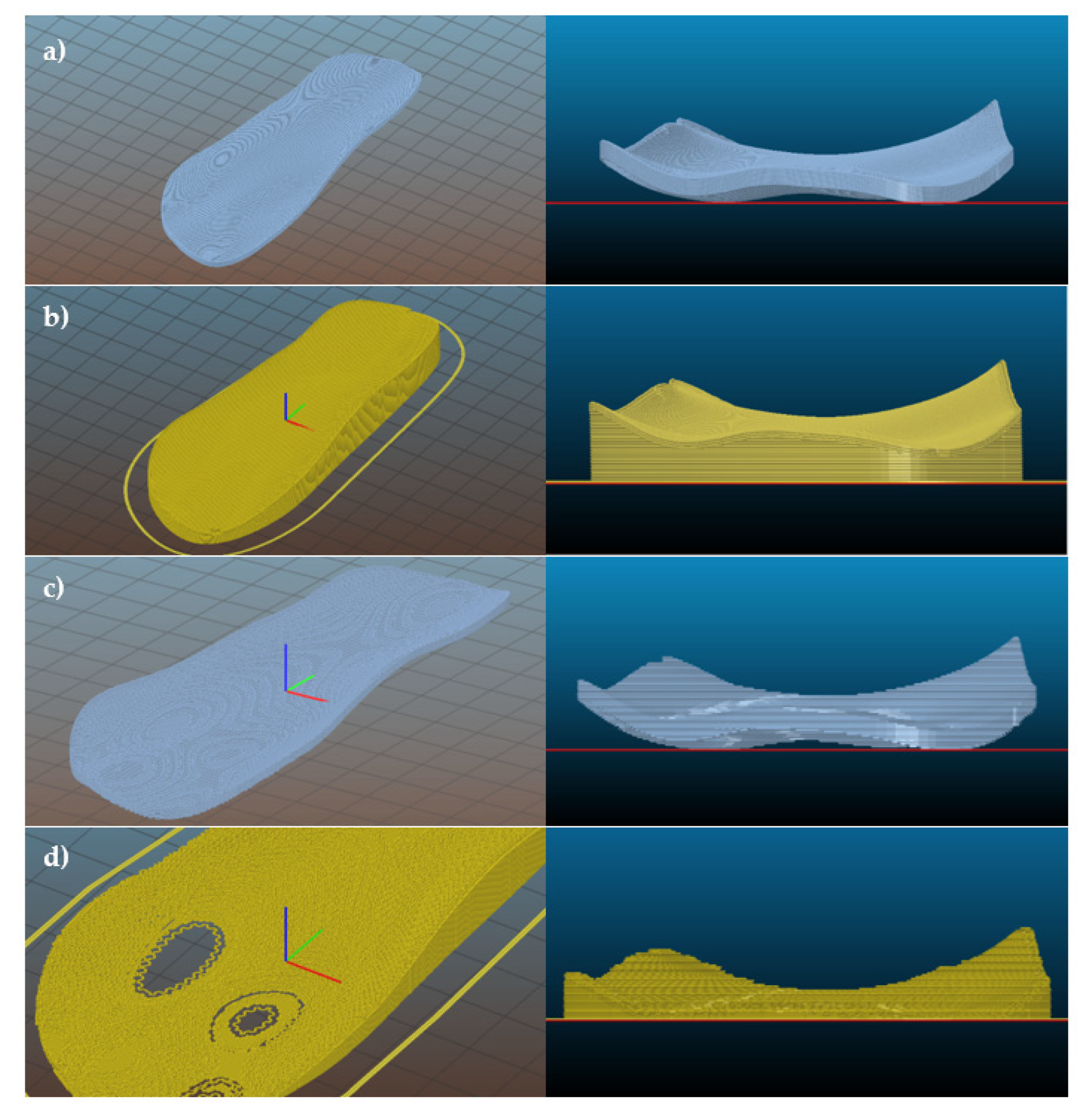
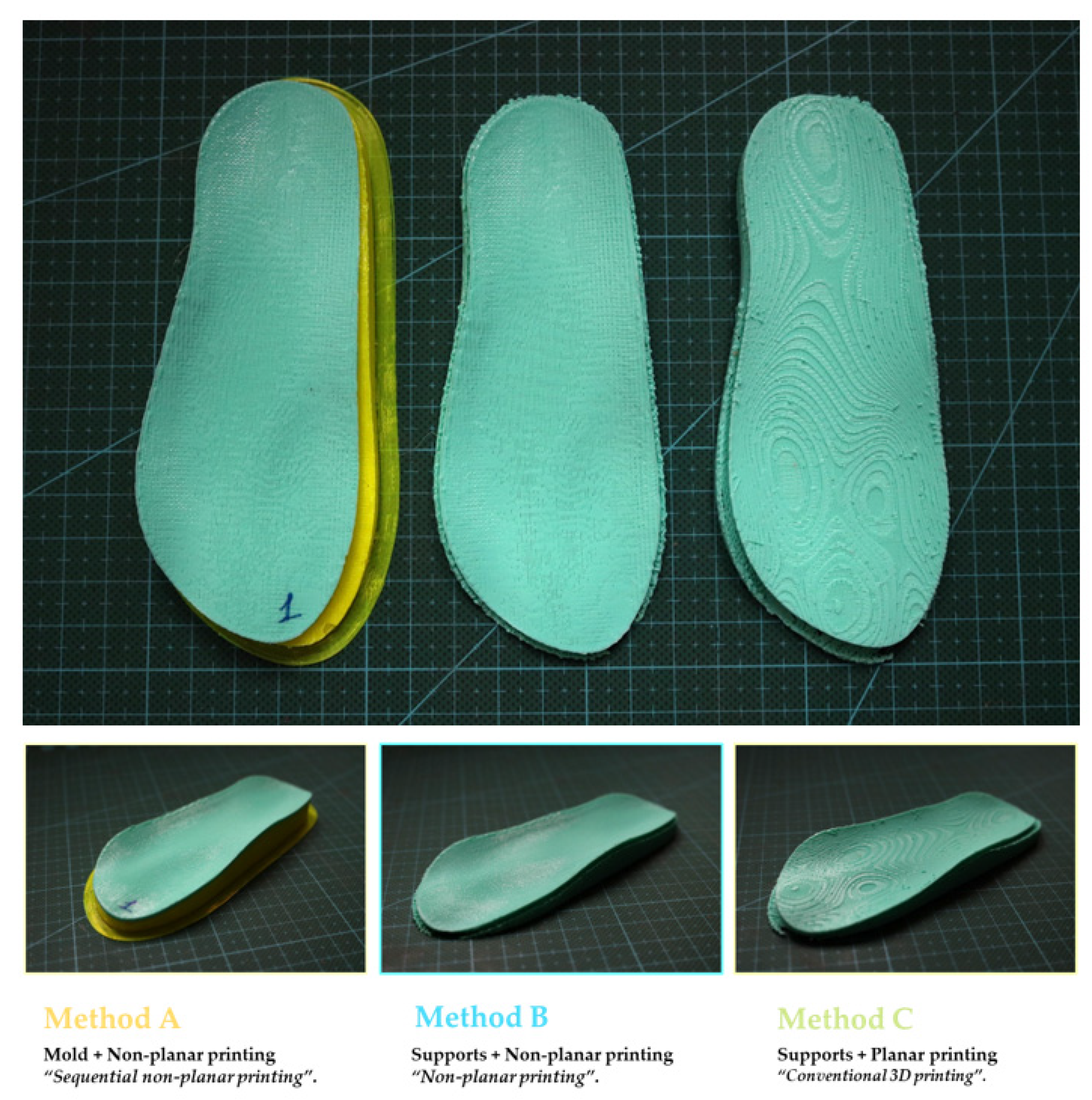
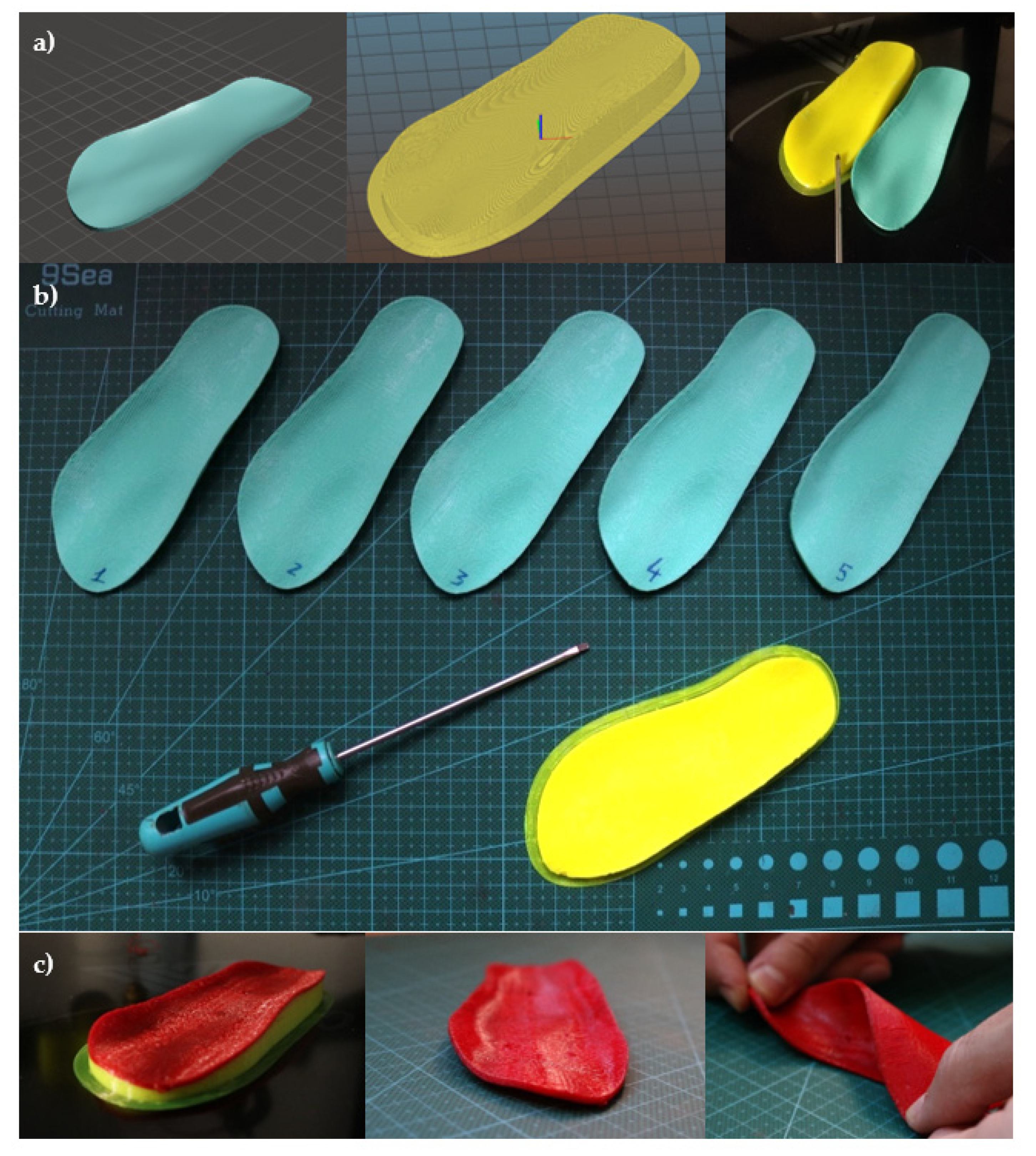
2.2. Fabrication Methods and Materials
2.3. Methods and Software Employed for Studying Environmental Impacts
3. Results
3.1. Main Results of the Study
3.2. Discussion and Future Proposals
4. Conclusions
Author Contributions
Funding
Institutional Review Board Statement
Informed Consent Statement
Data Availability Statement
Acknowledgments
Conflicts of Interest
References
- Medellin-Castillo, H.I.; Zaragoza-Siqueiros, J. Design and manufacturing strategies for fused deposition modelling in additive manufacturing: A review. Chin. J. Mech. Eng. 2019, 32, 1–12. [Google Scholar] [CrossRef]
- Vyavahare, S.; Teraiya, S.; Panghal, D.; Kumar, S. Fused deposition modelling: A review. Rapid Prototyp. J. 2020, 26, 176–201. [Google Scholar] [CrossRef]
- Micalizzi, S.; Díaz Lantada, A.; De Maria, C. Shape-memory actuators manufactured by dual extrusion multimaterial 3D printing of conductive and non-conductive filaments. Smart Mater. Struct. 2019, 28, 105025. [Google Scholar] [CrossRef]
- Lifset, R. 3D printing and industrial ecology. J. Ind. Ecol. 2017, 29, 6–8. [Google Scholar] [CrossRef]
- Ahlers, D. 3D Printing of Nonplanar Layers for Smooth Surface Generation. Master’s Thesis, Universität Hamburg, Hamburg, Germany, 2018. [Google Scholar]
- Ahlers, D.; Wasserfall, F.; Hendrich, N.; Zhang, J. 3D printing of nonplanar layers for smooth surface generation. In Proceedings of the IEEE 15th International Conference on Automation Science and Engineering (CASE), Vancouver, BC, Canada, 22–26 August 2019; pp. 1737–1743. [Google Scholar]
- Sherwood Page, J. Systems and methods for improved 3D printing. U.S. Patent US10005126B2, 19 March 2014. [Google Scholar]
- Chakraborty, D.; Aneesh Reddy, B.; Roy Choudhury, A. Extruder path generation for curved layer fused deposition modeling. Comp. Aided Des. 2008, 40, 235–243. [Google Scholar] [CrossRef]
- Diegel, O.; Singamneni, S.; Huang, B.; Gibson, I. Curve layer fused deposition modeling in conductive polymer additive manufacturing. Adv. Mater. Res. 2011, 199–200, 1984–1987. [Google Scholar] [CrossRef]
- Singamneni, S.; Roy Choudhury, A.; Diegel, O.; Huang, B. Modeling and evaluation of curved layer fused deposition modeling. J. Mater. Process. Technol. 2012, 212, 27–35. [Google Scholar] [CrossRef]
- Chen, L.; Chung, M.-F.; Tian, Y.; Joneja, A.; Tang, K. Variable-depth curved layer fused deposition modeling of thin-shells. Robot. Comp. Integr. Manuf. 2019, 57, 422–434. [Google Scholar] [CrossRef]
- Huang, B.; Singamneni, S. Curve layer fused deposition modeling with varying raster orientations. Appl. Mech. Mater. 2014, 446–447, 263–269. [Google Scholar]
- Díaz Lantada, A.; de Blas Romero, A.; Sánchez Isasi, A.; Garrido Bellido, D. Design and performance assessment of innovative eco-efficient support structures for additive manufacturing by photo-polymerization. J. Ind. Ecol. 2017, 21, 179–190. [Google Scholar] [CrossRef]
- Cheng, A. How Adidas Plans to Bring 3D Printing to the Masses. 22 May 2018. Available online: https://www.forbes.com/sites/andriacheng/2018/05/22/with-adidas-3d-printing-may-finally-see-its-mass-retail-potential/?sh=2a101d24a607 (accessed on 3 February 2021).
- Thingiverse. Human Female/Lady Right and Left Feet Model by Znanzhu. 7 November 2016. Available online: https://www.thingiverse.com/thing:1876380 (accessed on 3 February 2021).
- Vogtländer, J.G. The Model of the Eco-Cost/Value Ratio. Available online: www.ecocostsvalue.com (accessed on 30 November 2020).
- IDEMAT App. Available online: http://idematapp.com/ (accessed on 30 November 2020).
- Iberdrola. Plan Estable. 2020. Available online: https://www.iberdrola.es/ (accessed on 30 November 2020).
- Munoz-Guijosa, J.M.; Zapata Martínez, R.; Martínez Cendrero, A.; Díaz Lantada, A. Rapid prototyping of personalized articular orthoses by lamination of composite fibers upon 3D-printed molds. Materials 2020, 13, 939. [Google Scholar] [CrossRef] [PubMed]
- Dröder, K.; Heyn, J.K.; Gerbers, R.; Wonnenberg, B.; Dietrich, F. Partial additive manufacturing: Experiments and prospects with regard to large series production. Procedia CIRP 2016, 55, 122–127. [Google Scholar] [CrossRef][Green Version]
- Falaudi, J.; Hu, Z.; Alrashed, S.; Braunholz, C.; Kaul, S.; Kassaye, L. Does material choice drive sustainability of 3D printing? Int. J. Mech. Mechatron. Eng. 2015, 9, 216–223. [Google Scholar]
- Godina, R.; Ribeiro, I.; Matos, F.T.; Ferreira, B.; Carvalho, H.; Peças, P. Impact Assessment of Additive Manufacturing on Sustainable Business Models in Industry 4.0 Context. Sustainability 2020, 12, 7066. [Google Scholar] [CrossRef]
- Colorado, H.A.; Gutiérrez Velásquez, E.I.; Neves Monteiro, S. Sustainability of additive manufacturing: The circular economy of materials and environmental perspectives. J. Mater. Res. Technol. 2020, 9, 8221–8234. [Google Scholar] [CrossRef]


| Magnitude | Value |
|---|---|
| 3D printer power consumption | 600 W |
| kWh price * | 0.1147 €/kWh |
| Polylactic acid (PLA) density | 1.24 g/cm3 |
| Spool PLA price | 17.9 €/kg |
| Polyethylene terephthalate glycol-modified (PETG) density | 1.29 g/cm3 |
| Spool PETG price | 20 €/kg |
| kg CO2/kg material (PLA) ** | 2.78 |
| kg CO2/kg material (PETG) ** | 2.94 |
| Eco-cost in €/kg material (PLA) ** | 0.4 €/kg |
| Eco-cost in €/kg material (PETG) ** | 0.42 €/kg |
| Symbol | Parameter and Unit |
|---|---|
| A | Mold printing time (min) |
| B | Non-planar insole (NPL) printing time (min) |
| C | Preparation time for method A (min) |
| D | Support structure printing time for method B (min) |
| C’ | Preparation time for method B (min) |
| E | Printing time for method C (support structure and planar insole (PL)) (min) |
| C” | Preparation time for method C (min) |
| ρPETG | PETG density (g/cm3) |
| ρPLA | PLA density (g/cm3) |
| Φ | Filament diameter (mm) |
| π | Number Pi |
| La = | PETG filament length for mold (mm) |
| Lb = | PLA filament length for NPL insole (methods A and B) (mm) |
| Lc = | Filament length for support structure for method B (mm) |
| Ld = | Filament length for method C (mm) |
| W | 3D printer power consumption (W) |
| P | Energy cost (€/kWh) |
| MPETG | PETG filament mass for method A (g) |
| MPLA | PLA filament mass for method A (g) |
| n | Number of copies |
| Q | PETG cost (€/kg) |
| R | PLA cost (€/kg) |
| Variable (Unit) | Method | Mathematical Expression |
|---|---|---|
| Production time Ti (min) | A | TA = A + n·(B + C) |
| B | TB = n·(B + D + C’) | |
| C | TC = n·(E + C”) | |
| Material consumption Mi (g) | A | MA = (π·(Φ2/4)·(ρPETG·La + ρPLA·n·Lb))/1000 |
| B | MB = (π·(Φ2/4)·ρPLA·n·(Lb + Lc))/1000 | |
| C | MC = (π·(Φ2/4)·ρPLA·n·Ld)/1000 | |
| Production costs Ci (€) | A | CA = W·TA·P·(60/3.6 × 106) + ((MPETG·Q + MPLA·R)/1000) |
| B | CB = W·TB·P·(60/3.6 × 106) + (MB·R/1000) | |
| C | CC = W·TC·P·(60/3.6 × 106) + (MC·R/1000) |
| Variable (Unit) | Method | Mathematical Expression |
|---|---|---|
| Electricity consumption ELCi (kWh) | A | ELCA = W·TA·(60/3.6 × 106) |
| B | ELCB = W·TB·(60/3.6 × 106) | |
| C | ELCC = W·TC·(60/3.6 × 106) | |
| CO2 equivalent kgCO2i (kg) | A | kgCO2A = (MPETG·2.94 + MPLA·2.78)/1000 + ELCA·0.41 |
| B | kgCO2B = (MB·2.78)/1000 + ELCB·0.41 | |
| C | kgCO2C = (MC·2.78)/1000 + ELCC·0.41 | |
| Eco-costs EC (€) | A | ECA = (MPETG·0.42 + MPLA·0.4)/1000 + ELCA·0.41·23.34/1000 |
| B | ECB = MB·0.4/1000 + ELCB·0.41·23.34/1000 | |
| C | ECC = MC·0.4/1000 + ELCC·0.41·23.34/1000 |
| Printing Time | Preparation Time * | Filament Length (mm) | Filament Volume (cm3) | Filament Mass (g) | |
|---|---|---|---|---|---|
| METHOD A | |||||
| Mold (PETG) | 1 h 6′ | 5′ | 6908 | 16.62 | 21.43 |
| Insole (NPL) | 1 h 6′ | 3′ | 4361 | 10.49 | 13.01 |
| METHOD B | |||||
| Support | 40′ | 3′ | 2902 | 6.98 | 8.66 |
| Insole (NPL) | 1 h 6′ | 12′ | 4361 | 10.49 | 13.01 |
| METHOD C | |||||
| Support + Insole (PL) | 1 h 44’ | 14′ | 7582 | 18.24 | 22.61 |
| n = | Batch Size (n) | |||||||
|---|---|---|---|---|---|---|---|---|
| 1 | 2 | 5 | 10 | 20 | 50 | 100 | ||
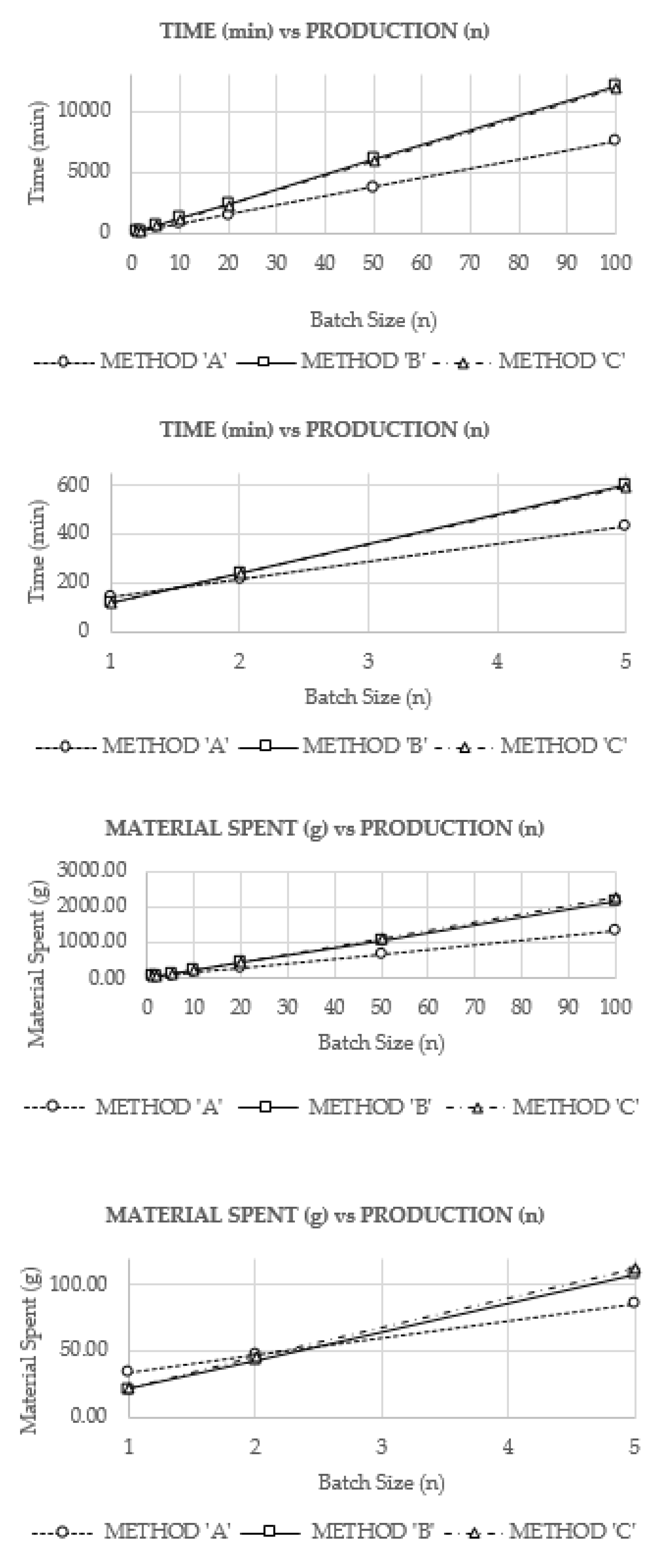
| Time SpentTi (min) | Method A | 140 | 214 | 436 | 806 | 1546 | 3766 | 7466 |
| Method B | 121 | 242 | 605 | 1210 | 2420 | 6050 | 12100 | |
| Method C | 118 | 236 | 590 | 1180 | 2360 | 5900 | 11800 | |
| Material Spent Mi (g) | Method A | 34.44 | 47.45 | 86.47 | 151.50 | 281.56 | 671.76 | 1322.09 |
| Method B | 21.66 | 43.32 | 108.31 | 216.62 | 433.23 | 1083.08 | 2166.16 | |
| Method C | 22.61 | 45.23 | 113.07 | 226.13 | 452.26 | 1130.65 | 2261.30 | |
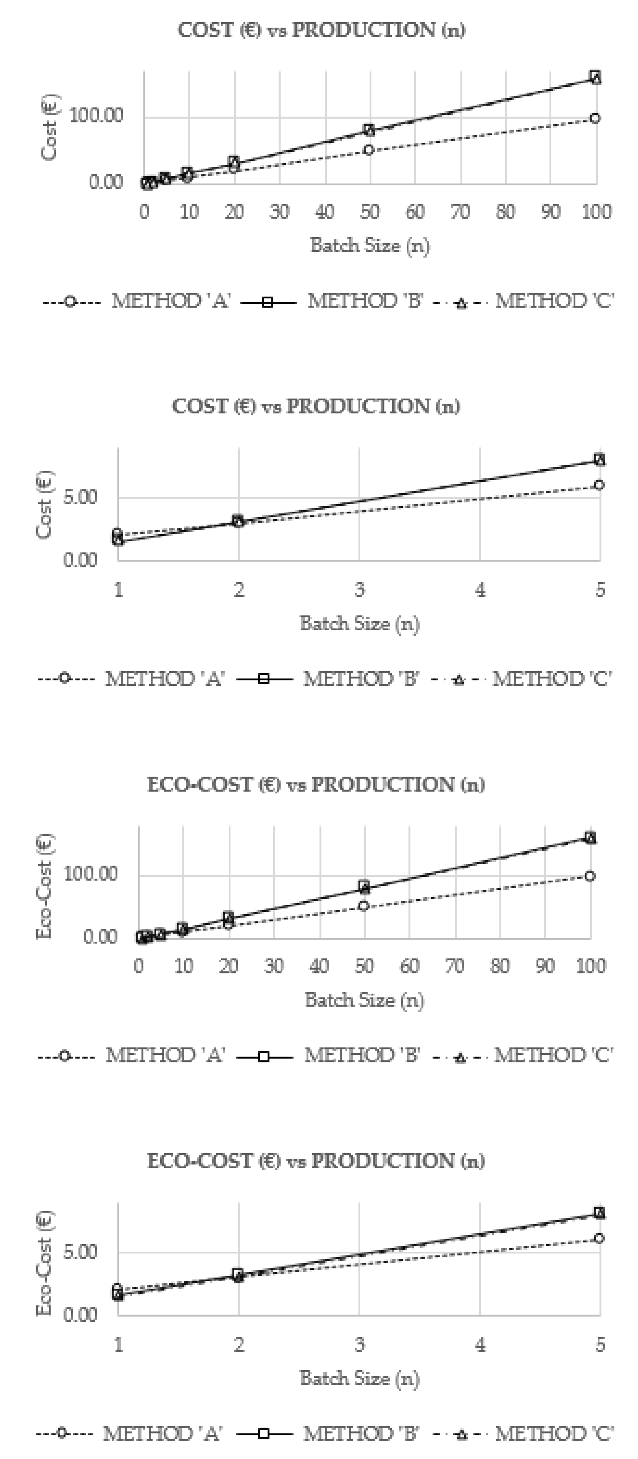
| Cost Ci (€) | Method A | 2.06 | 3.03 | 5.95 | 10.82 | 20.55 | 49.73 | 98.37 |
| Method B | 1.60 | 3.20 | 7.99 | 15.98 | 31.95 | 79.89 | 159.77 | |
| Method C | 1.58 | 3.17 | 7.92 | 15.85 | 31.70 | 79.24 | 158.48 | |
| Eco-cost ECi (€) | Method A | 2.09 | 3.07 | 6.03 | 10.95 | 20.81 | 50.36 | 99.61 |
| Method B | 1.62 | 3.24 | 8.09 | 16.18 | 32.36 | 80.90 | 161.80 | |
| Method C | 1.61 | 3.21 | 8.03 | 16.05 | 32.10 | 80.26 | 160.51 | |
Publisher’s Note: MDPI stays neutral with regard to jurisdictional claims in published maps and institutional affiliations. |
© 2021 by the authors. Licensee MDPI, Basel, Switzerland. This article is an open access article distributed under the terms and conditions of the Creative Commons Attribution (CC BY) license (http://creativecommons.org/licenses/by/4.0/).
Share and Cite
Cendrero, A.M.; Fortunato, G.M.; Munoz-Guijosa, J.M.; De Maria, C.; Díaz Lantada, A. Benefits of Non-Planar Printing Strategies Towards Eco-Efficient 3D Printing. Sustainability 2021, 13, 1599. https://doi.org/10.3390/su13041599
Cendrero AM, Fortunato GM, Munoz-Guijosa JM, De Maria C, Díaz Lantada A. Benefits of Non-Planar Printing Strategies Towards Eco-Efficient 3D Printing. Sustainability. 2021; 13(4):1599. https://doi.org/10.3390/su13041599
Chicago/Turabian StyleCendrero, Adrián Martínez, Gabriele Maria Fortunato, Juan Manuel Munoz-Guijosa, Carmelo De Maria, and Andrés Díaz Lantada. 2021. "Benefits of Non-Planar Printing Strategies Towards Eco-Efficient 3D Printing" Sustainability 13, no. 4: 1599. https://doi.org/10.3390/su13041599
APA StyleCendrero, A. M., Fortunato, G. M., Munoz-Guijosa, J. M., De Maria, C., & Díaz Lantada, A. (2021). Benefits of Non-Planar Printing Strategies Towards Eco-Efficient 3D Printing. Sustainability, 13(4), 1599. https://doi.org/10.3390/su13041599