Article

Humidification-Dehumidification Desalination System Powered by Simultaneous Air-Water Solar Heater

1
Department of Mechanical Convergence Engineering, School of Mechanical Engineering, Hanyang University, 222 Wangsimni-ro, Seongdong-gu, Seoul 04763, Korea
2
ERICA Industry-University Cooperation Foundation, Hanyang University, 55 Hanyangdaehak-ro, Sangnok-gu, Ansan 15588, Gyeonggi-do, Korea
3
Department of Mechanical Engineering, Hanyang University, 55 Hanyangdaehak-ro, Sangnok-gu, Ansan 15588, Gyeonggi-do, Korea
4
BK21 FOUR ERICA-ACE Center, Hanyang University, 55 Hanyangdaehak-ro, Sangnok-gu, Ansan 15588, Gyeonggi-do, Korea
*
Author to whom correspondence should be addressed.
Sustainability 2021, 13(23), 13491; https://doi.org/10.3390/su132313491
Submission received: 12 October 2021 / Revised: 27 November 2021 / Accepted: 2 December 2021 / Published: 6 December 2021
(This article belongs to the Section Sustainable Water Management)

Abstract

:
A humidification–dehumidification (HDH) desalination system requires thermal energy to desalt seawater. An environmentally friendly approach to obtain thermal energy is to utilize solar energy using solar collectors. Either seawater or air (or both) are typically preheated by HDH desalination systems before these fluids are conveyed to the humidifier column. Compared with preheating only air or water, preheating both is preferred because improved performance and higher productivity are achieved. Many researchers have proposed dual preheated HDH systems utilizing two separate solar heaters/collectors for simultaneous air–seawater preheating. In this study, dual-fluid preheating is achieved using a single solar collector. The proposed simultaneous air–water solar heater (SAWSH) is a modified flat-plate collector designed for simultaneously preheating air and seawater before the fluids reach the humidifier. A thermodynamic study was conducted using formulated mathematical models based on energy and mass conservation principles. Then, the dual-fluid heating HDH system is compared with HDH systems in which only air or only water is heated. This work found that the former outperformed the latter. The daily and monthly performance levels of the system in terms of the outlet temperatures of air and water, distillate rate, and gain output ratio were calculated using the weather data of the hot and humid climate of Jeddah City, Saudi Arabia.

1. Introduction

Many countries around the globe, mainly those in arid regions, lack access to potable water. According to the recent United Nations world water development report 2021, approximately 2 billion people globally suffer due to water stress, and 4 billion reside in regions with physical water scarcity [1]. In addition, approximately 1.6 billion people reside in areas of economic water scarcity. In view of the foregoing, and to resolve the problem of potable water demand and shortage, saline water desalination is deemed as a potential solution. Remarkably, although these regions lack water, they are exposed to abundant solar radiation that can be effectively utilized for the desalination process [2]. Solar energy is considered as an environmentally friendly, economical, and energy-efficient clean form of renewable energy that can be utilized to harness potable water through solar desalination [3]. Further, to solve the problem of freshwater demand in remote and arid areas across the globe where the amount of electric energy is limited, energy-efficient and cost-effective decentralized water production plants are required. A technique identified to be an innovative and favorable technology for freshwater production at a small scale (or) decentralized level is humidification–dehumidification (HDH) thermal-based desalination [4]. This technique has attracted sufficient interest for research because of its advantages. It can operate at low temperatures and use any low-grade waste heat for powering the system. It is cost effective, can adopt local materials for construction, and can be possibly integrated with sustainable energy resources, such as solar and biomass [5,6]. In addition, one of the main advantages of this technology is the use of separate humidification and dehumidification components for the thermal desalination process. Hence, each element can be designed independently based on requirements and operational constraints [7]. The HDH system allows considerable thermodynamic flexibility in the vaporization of water as heat transfer fluid (HTF) into the air medium during humidification, as well as the subsequent condensation of saturated vapor through latent heat recovery during dehumidification [8]. In general, the thermal energy required to operate the HDH system is supplied using fossil fuel, industrial waste heat, geothermal energy, biomass energy, or solar energy [4,9]. For solar energy to be energy efficient and cost effective for powering HDH systems, the following are necessary: solar flat-plate collector (FPC), parabolic trough collector (PTC), evacuated tube collector (ETC), and Fresnel lens collector (FLC).
Santosh et al. [3] conducted a detailed review of solar-based HDH desalination systems powered by different solar collectors. They highlighted the advantages of different solar collectors on preheating water and air HTFs in HDH systems. They found that the freshwater production rate in any HDH system mainly depends on the mass flow rates of water and air, temperatures of these fluids across the humidifier inlet, and solar radiation intensity. The study suggested that the adoption of combined solar collectors, such as FPC with high-efficiency FLC or ETC within HDH desalination, has considerable potential for augmenting the overall HDH process efficiency, subsequently improving freshwater productivity. It was further reported that the use of a dual-fluid (water and air) preheating system compared with a single-fluid preheating mechanism contributed to higher system efficiency.
Mohamed et al. thermodynamically evaluated the suitability of the HDH unit with a solar PTC for preheating the air HTF [10]. Individual system components were modeled, and HDH performance was assessed in winter, spring, summer, and autumn. Results indicated that freshwater productivity was higher (0.5 kg/kg of air HTF) during summer owing to the high solar radiation intensity and longer solar time compared with other seasons. An experimental evaluation of an HDH system equipped with a bubble column air humidifier involving preheated water HTF supply from a solar evacuated tube collector was implemented by Khalil et al. [11]. The HDH system productivity, efficiency, and gain output ratio (GOR) were 21 kg, 63%, and 0.53, respectively. The authors concluded that the performance of the air bubble column humidifier with preheated water compared with conventional packed-bed humidifier units was higher. Yildirim et al. [12] conducted a parametric study that involved preheating water and air HTFs using a solar flat-plate water collector and double-pass air heaters. A comparative investigation evaluating the performance of an HDH system when only water is heated, only air is heated, and both water and air are heated was implemented. Compared with the single-fluid heating process, the HDH system with dual-HTF preheating was found to contribute to higher freshwater productivity.
Sharshir et al. [13] employed an evacuated solar water heater to operate an HDH system. Their system had a hybrid solar-driven desalination unit comprising an HDH and four solar stills. Hot brine water from the HDH unit was reprocessed by feeding it into the solar stills to utilize the water’s residual heat. Their results indicated that the GOR increased by up to 50%, and the single solar still efficiency improved up to 90%. The maximum production rate of freshwater was 63.3 kg/d, and the estimated cost of freshwater using this system was USD 0.034/L. Experimental investigations were conducted by Antar and Sharqawy to evaluate the performance of air-heated single-stage and two-stage solar HDH desalination systems [14]. The fabricated systems were tested on the seashore of Dhahran, Saudi Arabia. Two ETCs were employed to preheat air before it is conveyed to the humidifier column, where it flows counter to sprayed raw water. Their results indicated that the productivity was 3.5 and 6 L/d for the single-stage and two-stage systems, respectively, indicating that the two-stage HDH system is more efficient. Dai et al. [15,16] analyzed a water-heated solar HDH desalination unit with forced air circulation in an open-air closed-water circulation. Their study identified that the performance of the system was highly reliant on parameters, such as the inlet temperature of water across the humidifier, mass flow rate of seawater, and mass flow rate of air. Moreover, they revealed that the humidifier inlet water temperature considerably affected freshwater productivity, and for each specific inlet water temperature value, the air and water mixing across the humidifier has an optimal ratio. Houcine et al. [17] evaluated the performance of an air-heated five-stage HDH system using an FPC with forced air circulation. The basic idea behind their process was the stepwise heating of air, followed by the humidification process. The fabricated five-stage HDH desalination unit was examined from March to August 2003. The unit’s freshwater productivity was ~355 kg/d, indicating the efficient operation of a stepwise-heated multistage HDH system. Orfi et al. [18] presented a water-heated and air-heated solar HDH desalination unit with two separate solar collectors for the simultaneous heating of water and air. The study was conducted based on a mathematical model involving energy and mass transfer mechanisms across the humidifier and dehumidifier units of the HDH system, considering the operation of the system in Monastir, Tunisia. Their results indicated that the system was able to produce more than 40 L of distilled water per square meter of solar collector per day during the month of July. Zhani and Bacha [19] also presented a solar desalination prototype using the HDH principle with two separate flat-plate solar collectors for air and water heating. They conducted an experimental study under the weather conditions of Sfax City, Tunisia. Their experimental results showed that the thermal performance of the system increased with solar radiation, thus achieving maximum thermal performance and higher production rate during the month of July.
A hybrid solar desalination system with water flash evaporation was presented by Kabeel et al. [20]. They proposed a dual water-heated and air-heated HDH unit equipped with an FPC and a double-pass dual-glass solar air heater, respectively. The maximum achievable GOR was approximately 4.5, and the authors concluded that an increase in the air heater collector area contributed to the increase in freshwater production rate. Yamali et al. [21] proposed an air-heated HDH system with the application of a double-pass flat-plate solar air heater. Their result showed that the distillate production increased up to 8% with the use of a double-pass FPC solar air heater and decreased by approximately 30% without utilizing this FPC under the same operating conditions. Moreover, they also reported that the air and water mass flow rates considerably affected the overall system production. The effect of various operating parameters, configuration, and weather conditions on the production rate of an HDH desalination system was theoretically studied by Nafey et al. [22,23]. The authors evaluated the system performance using four configurations: air heating, water heating, air–water heating in a closed loop, and air–water heating in an open loop. A concentrating solar water-heating collector and a flat-plate solar air-heating collector were used. They revealed that the production rate of the system increased with the air mass flow rate, water collector area, and input solar energy. However, the productivity of the unit was observed to decrease with increasing water mass flow rate. The authors also reported that wind speed and ambient temperature only had a slight influence on the HDH system’s performance.
In addition to the adoption of an HDH system with a single HTF preheating process and a dual-fluid preheating system using two separate collectors, a few research works have also been conducted on the preheating of both HTFs using a single solar collector. Rajaseenivasan et al. utilized a dual-purpose solar collector (DPSC) to simultaneously heat water and air HTFs prior to their entry into the humidifier unit of an HDH system [24]. The passage of water and air media was through the bottom and top of the DPSC’s absorber plate. Results indicated that the system’s productivity values were approximately 12.36, 14.14, and 15.23 kg/m2∙d with the use of DPSC with no turbulators, with convex turbulators, and with concave turbulators, respectively. Similarly, a number of novel studies have focused on utilizing a Fresnel lens solar collector to simultaneously preheat both HTFs. Wu et al. conducted theoretical and experimental investigations of a novel Fresnel lens collector-preheated HDH system involving the simultaneous heating of water and air media in the humidification chamber loaded with ceramic packing materials [25]. Their results indicated that a single Fresnel lens collector was efficient in preheating both HTFs, contributing to improved freshwater productivity and GOR of approximately 3.4 kg/h and 2.1, respectively. The work was further extended by Xiao et al., with the adoption of bubbling humidification and dehumidification techniques [26]. With the developed HDH system, the attained maximum freshwater production rate and average thermal efficiency were approximately 7.3 kg/d and 71%, respectively.
Thus, the foregoing indicates that researchers have predominantly worked on preheating a single HTF in an HDH system or two HTFs (water and air) using two different solar collectors. Research on the use of a single solar collector to preheat two HTS in an HDH system is limited. In addition, experimental studies on overcoming obstacles in the optimization of system and process parameters to achieve maximum system efficiency and improve freshwater productivity are also few. Further, the literature reports that the cost of using a Fresnel lens solar collector for preheating dual fluids compared with employing simple solar heating devices is higher, thus substantially contributing to the increase in capital cost and freshwater production cost [27]. Accordingly, the primary objective of the current work is to mathematically investigate the performance of an HDH system equipped with a novel simultaneous air–water solar heater (SAWSH) unit and optimize significant system process parameters to achieve maximum freshwater productivity. Further, major HDH system parameters are validated with reported experimental results to evaluate the proposed model accurately.

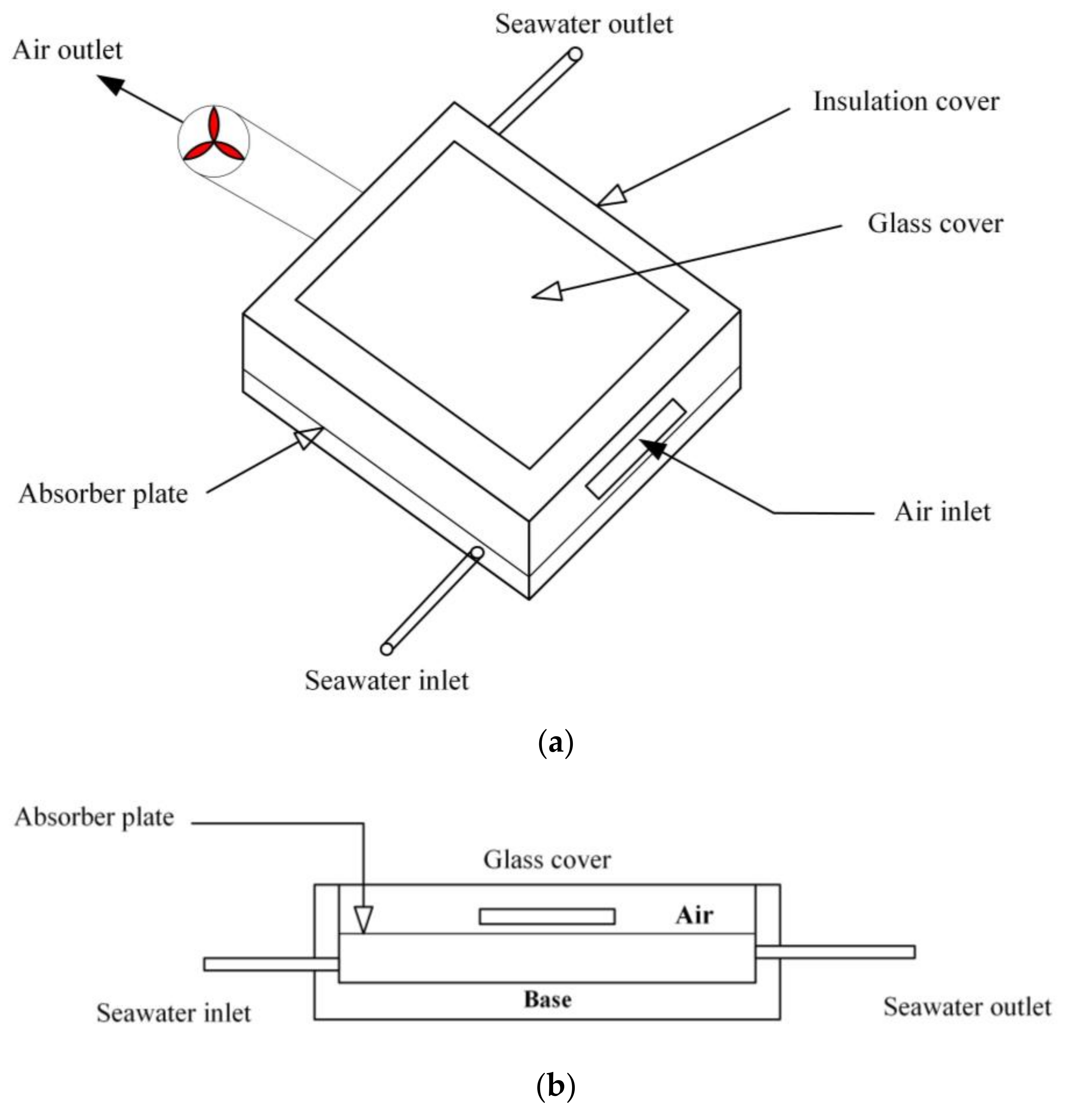
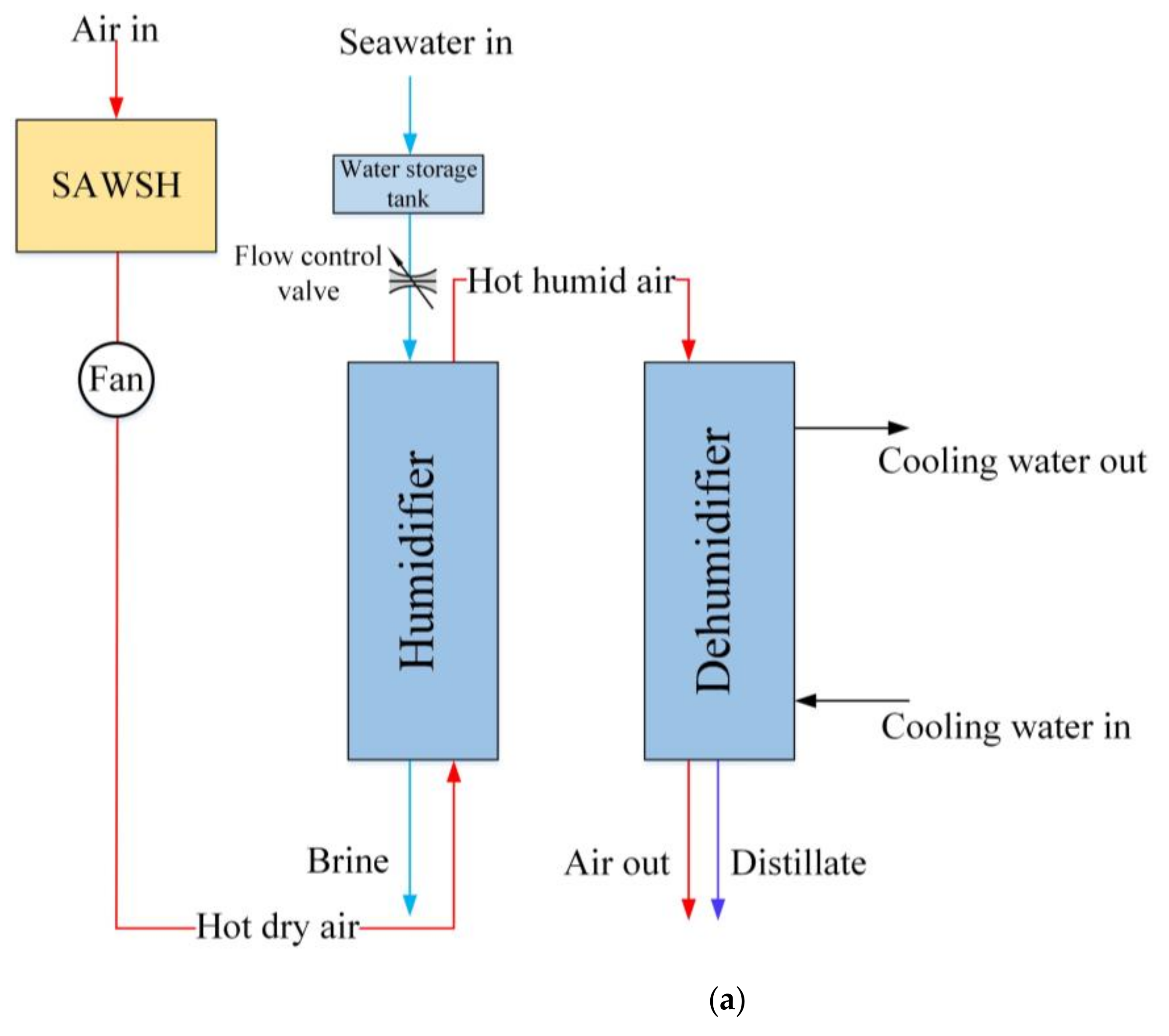
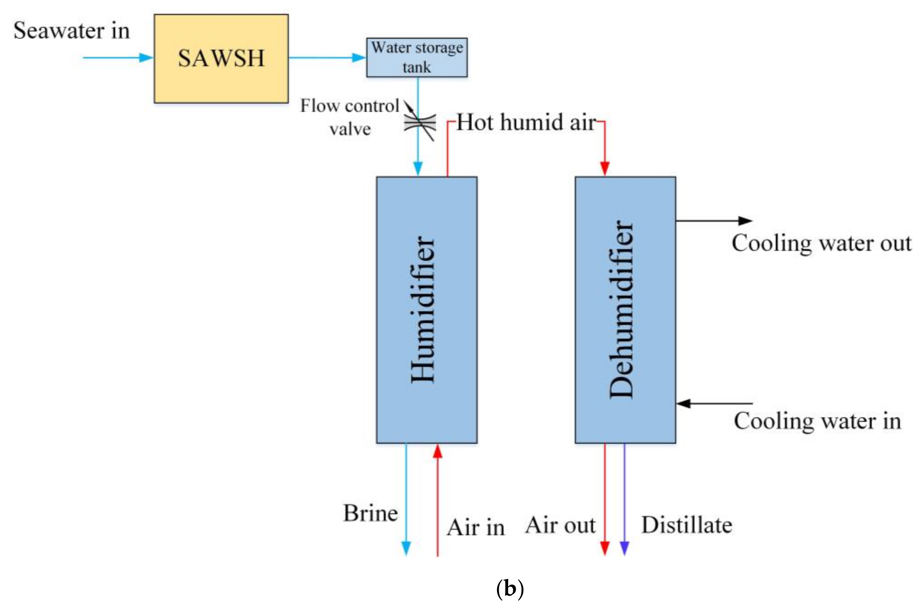
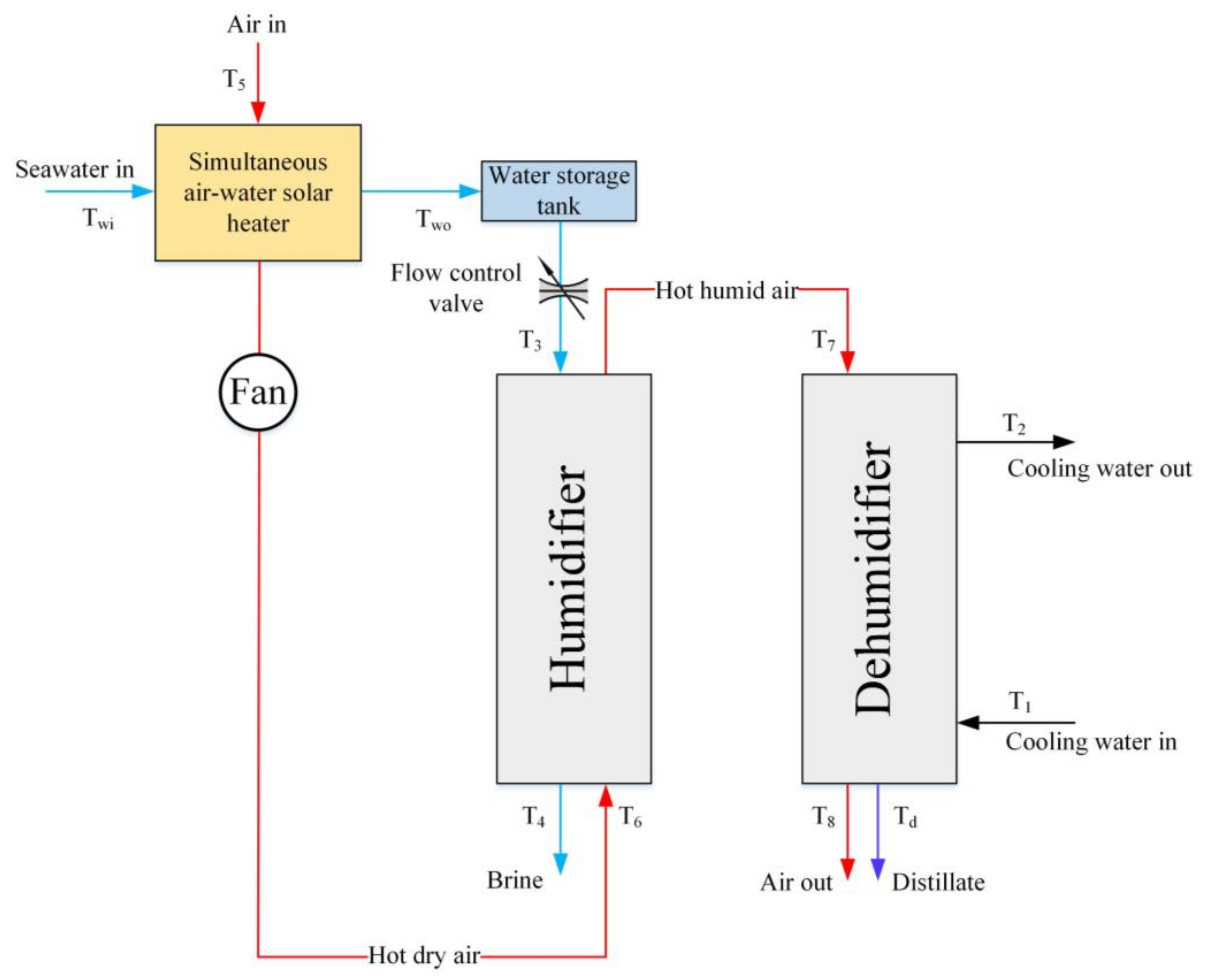
2. System Description

The proposed HDH system equipped with SAWSH adopted for simultaneously preheating water and air HTFs using a single solar collector is illustrated in Figure 1. The major components of the HDH system include a SAWSH, a seawater storage tank, a constant effectiveness humidifier unit, and dehumidifier units. The proposed SAWSH consists of upper and lower sections. A common absorber plate separating the upper and lower sections is employed, as shown in Figure 2a. The lower section is utilized for heating the water HTF, and the upper section is involved in preheating the air HTF. Furthermore, for effective dual-fluid preheating, the sides and bottom of the SAWSH are well insulated to prevent convection and radiative heat losses to the atmosphere. Similarly, for effective heat transfer, a common absorber plate painted with a black coating is placed between the upper and lower sections of the SAWSH, as depicted in Figure 2b. Solar energy is efficiently absorbed by the absorber plate in the form of heat. Subsequently, thermal energy is transferred to the water HTF in the lower section and air HTF in the upper section of the SAWSH. Air flow is maintained with the support of an exhaust fan at the airside exit in the SAWSH, and a constant temperature water tank is utilized for storing the exit water of the SAWSH; this water is continuously supplied to the humidifier unit. This is because water in the lower portion is stationary, whereas the water flow for the HDH system is regulated using a control valve across the humidifier unit.
The dimensions and process parameters of the SAWSH unit are summarized in Table 1. The HDH process involves the simultaneous initial preheating of both the seawater and air HTFs (dual-fluid preheating) in the SAWSH unit. The preheated water is further sprayed in a counter-flow packed-bed humidifier unit (similar to a forced-air cooling tower) from the top. Similarly, hot dry air is allowed to enter from the bottom of the humidifier unit to interact with the counter-flowing water HTF, thus contributing to the humidification effect. The humidified air further passes through the cross-flow heat exchange dehumidifier unit where it interacts with the coolant. This contributes to the latent heat extraction from the humidified air for freshwater production through the dehumidification process. The dehumidified air is discharged to the atmosphere, and brine is collected at the bottom of the humidifier unit; accordingly, the HDH process is in open-water open-air circulation mode.

3. Mathematical Modeling

To achieve efficient solar HDH desalination with simultaneous dual-fluid preheating, a mathematical model consisting of a SAWSH unit and an HDH desalination system was formulated. The following are assumed for modeling the HDH system with simultaneous water and air preheating.
  • The system operates under a steady-state condition.
  • The flow of fluids in the system is considered incompressible assuming the constant properties, since the air was assumed as ideal gas [29,30].
  • Pressure and heat losses from the HDH system components are neglected.

3.1. Modeling of SAWSH Unit

The SAWSH model was developed based on the energy balance of HTFs and various components involved in it, including the glass cover, absorber plate, collector base, and water and air HTFs. The governing equations involved are discussed below.

3.1.1. Glass Cover

The energy balance for the glass cover is given by [28]:
U o T g c T a m =   h a g c T a i r T g c +   h r p g c T a p T g c +   α g c S
where Uo is the overall heat transfer coefficient between the glass cover and surroundings, Tgc denotes the glass cover temperature, Tam is the ambient temperature, hagc is the convective heat transfer coefficient between the glass cover and air, Tair is the temperature of air flowing through the upper compartment, hrpgc denotes the radiative heat transfer coefficient between the absorber plate and glass cover, Tap denotes the absorber plate temperature, αgc denotes the absorptance of the glass cover, and S is the solar radiation intensity. The total overall heat transfer coefficient, Uo, is the summation of convective and radiative heat transfer coefficients between the glass cover and surroundings, as follows:
U o = h g c a + h r a m
where hgca denotes the convective heat transfer coefficient between the glass cover and ambient, and hram is the radiative heat transfer coefficient between the glass cover and ambient air.
Further, hgca, hram, and hrpgc are calculated using Equations (3)–(5), respectively [31]:
h g c a = 2.8 + 3 v a i r
h r a m = ε g c   σ   T g c + 273 4 T a m + 267 4 T g c T a m
h r p g = ε p   σ T a p + 273 4 T g c + 273 4 T a p T g c
where εgc and εp denote the emissivities of the glass cover and plate, respectively. Moreover, hagc in Equation (1) can be calculated as [32]:
h a g c = k a i r D e 0.0158 R e 0.8
where kair is the thermal conductivity of air HTF, and De denotes the equivalent/hydraulic diameter, which is used when considering the flow across noncircular tubes and channels. This diameter is calculated as
D e = 4 C P
where C and p denote the cross-section and wetted perimeter in the upper compartment, respectively.

3.1.2. Air Stream

The air stream energy balance for the differential length, dx, is:
m ˙ a i r c a i r d T a i r d x = h a g c W T g c T a i r + h a a p W T a p T a i r
where m ˙ a i r is the mass flow rate of air through the upper compartment, cair is the specific heat of air, and haap is the convective heat transfer coefficient between the absorber plate and air. Here, hagc = haap, whereas W is the width of the collector. Therefore, Equation (8) can be rewritten as:
T a i r L = A 1 T a p + B 1
From Equations (1) and (9), Tgc is derived as:
T gc = A 2 + B 2 T a p
where A1, A2, B1, and B2 are arbitrary constants of integration, defined as follows:
A 1 = B A   1 e x p A L
B 1 = C A   1 e x p   A L + T a o e x p   A L
A = W m ˙ a i r c a i r   h a a p + h a g c h a g c h a a g U o + h r p g c + h a g c
B = W m ˙ a i r c a i r   h a g c h a g c h r p g c U o + h r p g c + h a g c h a a p
C = W m ˙ a i r c a i r   h a g c U o T a m + α g c S U o + h r p g c + h a g c
A 2 = U o T a m + α g c S U o + h r p g c + h a g c + h a g c B 1 U o + h r p g c + h a g c
B 2 = h a g c A 1 U o + h r p g c + h a g c + h r p g c U o + h r p g c + h a g c

3.1.3. Absorber Plate

The energy balance for the absorber plate is represented as:
α τ S = h a a p T a p T a i r + h r p g c T a p T g c + h p w T a p T w
where ατ is the absorptance–transmittance product, and hpw denotes the convective heat transfer coefficient between the plate and water.
From Equations (9)–(18), Tap is given by:
T a p = A 3 + B 3 T w
where A3 and B3 are given as:
A 3 = α τ   S + h a a p B   1 + h r p g c A 2 h a a p A 1 h a a p + h p w + h r p g c B 2 h r p g c
B 3 = h p w h a a p A 1 h a a p + h p w + h r p g c B 2 h r p g c
where Tw is the temperature of water in the lower compartment.

3.1.4. Base

The energy balance across the base of the collector is defined as:
h p w T w T b = U b a T b T a m
where Uba is the overall heat transfer coefficient between the base and ambient air. The temperature at the bottom, Tb, is given by:
T b = A 4 + B 4 T w
where:
A 4 = U b a T a m U b a + h p w
B 4 = h p w U b a + h p w
The overall bottom loss coefficient is as follows [29]:
U b a = t i K i + 1 h b a 1
where ti and Ki are the thickness and thermal conductivity of insulation, respectively. The convective heat transfer coefficient, hba, between the bottom and ambient air is given by [31] as follows:
h b a = 2.8 + 3 v a i r
where vair is the ambient air velocity.

3.1.5. Water

The energy balance for water is given by:
M w c w d T w d t = h p w T a p T w A p h p w T w T b A p
where Mw is the mass of water in the collector, cw denotes the specific heat of water, and Ap is the area of the absorber plate.
The above equation can be rewritten as:
d T w d t + A 5 T w = B 5
T w t = B 5 A 5 1 e x p   A 5 t + T w i exp   A 5 t
where:
A 5 = A p h p w A p h p w B 3 + A p h p w A p B 4 h p w M w c w
B 5 = A p A 3 h p w + A p A 4 h p w M w c w
and Twi is the initial water temperature at time t = 0.
The SAWSH model was developed using MATLAB R2019b software. The water outlet temperature was derived from Equation (30), considering the 1 h time step and the initial water temperature, Twi, at time t = 0. After finding the value of Tw (t), the temperature of exit air, Tair(L), is calculated. Water is constantly withdrawn from the collector every hour and stored in a storage tank. Water from the storage tank is supplied to the humidifier according to the desired flow rate using the flow control valve. Further, air is circulated from the SAWSH to the humidifier using a fan.

3.2. Modeling of HDH System

The mass and energy balance equations of humidification–dehumidification processes are presented in this section. Under steady-state and no-heat-loss conditions, the energy balance during the humidification process is described as [33]:
m ˙ w H w 3 + m ˙ a i r H a 6 = m ˙ b H w 4 + m ˙ a i r H a 7
where Hw3 and Hw4 are the enthalpy of seawater at the inlet and outlet of the humidifier unit, respectively. Further, Ha6 and Ha7 are the enthalpies of air at the humidifier inlet and exit, respectively; and m ˙ w , m ˙ a i r , and m ˙ b denote the mass flow rates of water, air, and brine, respectively.
The mass balance in the humidifier unit is expressed as:
m ˙ b = m ˙ w m ˙ a i r ω 7 ω 6
where ω7 is the humidity ratio at the humidifier, and ω6 is the humidity ratio at the humidifier inlet.
The effectiveness of the humidifier is determined by [33]:
ε h =   max H a 7 H a 6 H a 7 , i d e a l H a 6   ,   H w 3 H w 4 H w 3 H w 4 , i d e a l
where Ha7,ideal is the ideal enthalpy of air at the humidifier outlet when the air temperature is equal to the inlet temperature of seawater, and Hw4,ideal is the ideal enthalpy of seawater at the humidifier outlet when the seawater temperature is equal to the temperature of air across the humidifier inlet [33].
The energy balance across the dehumidifier is given by [34]:
m ˙ c w c w T 1 + m ˙ a i r H a 7 = m ˙ c w c w T 2 + m ˙ d H d + m ˙ a i r H a 8
where m ˙ c w is the cooling water mass flow rate; T1 and T2 are the temperatures of cooling water at the dehumidifier inlet and outlet, respectively; m ˙ d denotes the mass flow rate of distillate; and Ha8 is the air enthalpy at the dehumidifier exit.
Similarly, the mass balance across the dehumidifier unit is expressed as:
m ˙ d = m ˙ a i r ω 7 ω 8
In Equation (36), Hd is the enthalpy of distillate at a temperature “Td”, which is taken as the average of the inlet and outlet air temperatures inside the dehumidifier. The salt concentration in pure water is assumed to be less than 500 ppm, which is safe for consumption [35].
The effectiveness of the dehumidifier is expressed as [33]:
ε d =   max H a 7 H a 8 H a 7 H a 8 , i d e a l   ,   H w 2 H w 1 H w 2 , i d e a l H w 1
where Ha8,ideal is the ideal enthalpy of air at the dehumidifier outlet based on the cooling water inlet temperature, and Hw2,ideal is the ideal enthalpy of cooling water at the dehumidifier inlet based on the inlet air temperature [34]; Hw1 and Hw2 are the enthalpies of the inlet and outlet cooling water across the dehumidifier unit, respectively.
The enthalpy of seawater is expressed as [36]
H w = H p w s   a 1 + a 2 s + a 3 s 2   + a 4   s 3 + a 5 T + a 6   T 2 + a 7 T 3 + a 8   s T + a 9 s 2 T + a 10 s T 2
where Hpw is the enthalpy of pure water, and s is the seawater salinity level. The coefficients used above are listed in Table 2.
The enthalpy of pure water is given by [36]
H p w = 141.355 + 4202.07   T 0.535   T 2 + 0.004   T 3
The enthalpy of humid air is computed by [37]
H a = c a i r + c v ω T + h f g ω
where cv is the heat capacity of vapor. The absolute humidity, ω, which is a function of relative humidity and dry air temperature, is expressed by the following [38]:
ω = 0.62198 × ϕ P s P a t m ϕ P s
where ϕ is the relative humidity, and Patm is the atmospheric pressure. The saturation pressure, Ps, is calculated by [12]:
P s = 2.7 × 10 9 × T 5 + 2.8 × 10 7 × T 4 + 2.7 × 10 5 × T 3 + 0.0014 × T 2 + 0.044 × T + 0.61
In Equation (41), hfg is the latent heat of water evaporation, which is expressed in a correlation that is valid over the temperature range 5–200 °C; it is given by [39]:
h f g = 2501.897149 2.407064037   T + 1.192217 × 10 3 T 2 1.5863 × 10 5 T 3
The performance of the HDH system is usually expressed with respect to the GOR, defined as [7]:
G O R =   m ˙ d h f g S A c o l
where S denotes radiation, and Acol is the collector area, which is fixed as 1.5 m2 [28].
The mathematical model of the HDH system, expressed by Equations (33)–(38), was solved using the fsolve function in MATLAB R2019b software. After solving these equations, productivity and GOR were calculated. Equations (39)–(44) are supplementary equations for determining the enthalpies of seawater and humid air.

4. Results and Discussion

The present study initially compared the individual air–water preheating and the dual-fluid preheating processes of an HDH system equipped with the SAWSH (SAWSH-HDH system) to identify the optimum preheating condition for achieving maximum freshwater productivity. The schematic of the SAWSH-HDH system with individual water- and air-preheating processes is shown in Figure 3. The SAWSH unit was utilized to preheat water and air HTFs individually, as depicted in Figure 3a,b, respectively. For the system that only preheats water, ambient air is directly supplied to the humidifier unit, whereas in the system that only preheats air, seawater is fed to the humidifier unit at the mean seawater temperature.
The freshwater productivity of the SAWSH-HDH system for a single day (21 June 2020) with an average solar radiation (from 7 a.m. to 5 p.m.) is depicted in Figure 4. At air and water mass flow rates of 0.020 and 0.029 kg/s, respectively, the maximum instantaneous freshwater productivity levels achieved when only water, only air, and both fluids are preheated are found to be approximately 3.43, 1.52, and 4.61 kg/h, respectively, as shown in Figure 5. The maximum instantaneous freshwater productivity was achieved at approximately 1 p.m. when the solar radiation was at its peak (935 W/m2). Compared with the individual HTF preheating process, the dual-fluid preheating process is found to contribute to higher freshwater productivity in the proposed SAWSH-HDH system. This can be attributed to the individual efficiency improvement of water and air HTFs with increasing temperature. The moisture-holding capacity of air HTF increases with temperature, thus achieving higher water-holding capacity in the preheated air medium [40]. With the increase in temperature of water HTF, water viscosity and surface tension decrease, resulting in the rapid movement and evaporation of water vapor into the air HTF during humidification [41]. These effects simultaneously improve the humidification during the dual-fluid preheating process. The effectiveness of the single-fluid preheating process is less than the effectiveness of the above process because of the single-fluid preheating effect, which reduces the effectiveness of the humidification process. Subsequently, the freshwater productivity during dehumidification is also reduced. Air improves its ability to carry more amounts of water vapor when heated; however, if only air is preheated, and the seawater entering the humidifier is colder than air, a low evaporation rate is achieved. In contrast, when only water is preheated, although the evaporation rate may be high, the capacity of unheated air to carry water is low. Thus, a higher distillate production rate is achieved in the HDH system with dual-fluid preheating, as shown in Figure 5.
Based on the instantaneous freshwater productivity, the calculated instantaneous GOR is shown in Figure 6. Because the GOR predominantly depends on freshwater productivity, a maximum instantaneous GOR of approximately 1.3 is achieved at 1 p.m. for the SAWSH-HDH system with dual-fluid preheating. The maximum instantaneous GOR values in systems where only water is preheated, and only air is preheated are approximately 1.18 and 0.88, respectively. A higher GOR is achieved by the system that only preheats water than the system that only preheats air. This is because the GOR is a function of productivity and inputted heat across the solar collector, as indicated by Equation (45). Consequently, with the same heat input, the productivity of the system that only preheats water is higher compared with that of the system that only preheats air. Hence, a higher GOR value is contributed by the former system.
Because HDH systems could efficiently operate in hot and humid climate conditions, the performance of SAWSH-HDH system was evaluated for the climate conditions of Jeddah City, Saudi Arabia. Dual-fluid preheating using the SAWSH unit was considered for further analysis because it has been identified as the most efficient method compared with individual water-preheating and air-preheating HDH processes, as discussed.
The average seawater surface temperature and ambient temperature measured at Jeddah City were considered seawater temperature and air HTF temperature at the SAWSH inlet, respectively [42]. The ambient temperature and average solar radiation are considered for a single day (21 June 2020) in Jeddah City, as depicted in Figure 4 [43]. The maximum and minimum solar radiation values, approximately 935 and 271 W/m2, occurred at 1 p.m. and 7 a.m., respectively. The maximum and minimum ambient temperature values, i.e., 36.56 and 28.21 °C, were observed at 1 p.m. and 7 a.m., respectively. The corresponding average seawater surface temperature was approximately 29 °C [42].
The average hourly performance of the SAWSH-HDH system with dual-fluid preheating from 7 a.m. to 5 p.m. was computed. The seawater and air temperature values at the SAWSH outlet are shown in Figure 7 and Figure 8, respectively. The highest instantaneous water medium temperature values at the SAWSH unit outlet were approximately 83, 78, and 73 °C at air mass flow rates of 0.005, 0.010, and 0.020 kg/s, respectively, at 1 p.m. Similarly, the highest air HTF temperature values at the SAWSH unit outlet were approximately 66, 62, and 57 °C at air mass flow rates of 0.005, 0.010, and 0.020 kg/s, respectively, at 1 p.m.
The increase in air mass flow rate was observed to reduce the air and seawater temperatures across the SAWSH collector outlet. This can be explained as follows. With increasing air mass flow rate, the contact time between the absorber plate and air tends to decrease. This causes air molecules to travel faster across the upper channel of the SAWSH without attaining higher temperatures. A higher air mass flow rate results in a higher Reynolds number. This increases the heat transfer from the absorber plate to the air stream, eventually reducing the heat transfer to the seawater stored inside the lower section of the SAWSH. As a result, a drop in seawater temperature at higher air mass flow rates is experienced.
The variation in instantaneous freshwater productivity over a single day with variations in the air mass flow rates is shown in Figure 9. The distillate rate is observed to be high at a low air mass flow rate, i.e., 0.005 kg/s. When the air mass flow rates further increased to approximately 0.010 and 0.020 kg/s, the freshwater productivity decreased. The maximum distillate rates at air mass flow rates of 0.005, 0.010, and 0.020 kg/s were found to be approximately 6.20, 5.78, and 4.61 kg/h, respectively, at a constant water mass flow rate of 0.029 kg/s. The optimal seawater mass flow rate at the humidifier was estimated to be 0.029 kg/s by the hit-and-trial method. The air mass flow rate exceeding 0.005 kg/s resulted in a decrease in the distillate rate. This was because the higher air mass flow rates reduced the time of contact between air and water in the humidifier. At air mass flow rates exceeding 0.005 kg/s, a decrease in distillate yield was observed owing to the reduction in the contact time between air and water HTFs across the humidifier unit, resulting in a lower humidification rate. Subsequently, during dehumidification, lower freshwater yield was achieved.
Based on the results obtained from the daily monitoring of the SAWSH-HDH system with the dual-fluid preheating process, the monthly performance was also evaluated using the monthly average solar radiation, seawater, and ambient temperature data for Jeddah City [42,43]. A year-round monthly average solar radiation and ambient temperature data for Jeddah City is shown in Figure 10. Compared with other months, the average solar radiation intensity was identified to be higher during the months of May, June, and July; these were 717, 712, and 704 W/m2, respectively. Similarly, the highest average ambient temperature was approximately 32 °C in August. The SAWSH unit performance was computed considering air mass flow rates of 0.005, 0.010, and 0.020 kg/s [28].
Figure 11 presents the monthly variation in air temperature in the SAWSH outlet with the variation in air mass flow rates. The average air temperature at the exit of the SAWSH unit was higher at lower air mass flow rates and lower for higher air mass flow rates. In June, the maximum air temperature values at the outlet, approximately 60, 57, and 53 °C, were obtained at air mass flow rates of 0.005, 0.010, and 0.020 kg/s, respectively. In December, the maximum air temperature values were approximately 37, 34, and 32 °C at air mass flow rates of 0.005, 0.010, and 0.020 kg/s, respectively. The higher temperature is attributed to the higher solar radiation intensity (approximately 712 W/m2) in June. In December, the outlet temperature was lower because of the lower solar radiation intensity (approximately 415 W/m2). Although the solar radiation in May was higher than that in June, the ambient temperature in May was less than that in June. Therefore, the maximum outlet temperature in June was higher than that in May.
The variation in seawater outlet temperature from the SAWSH unit at various air mass flow rates is depicted in Figure 12. Similar to daily variation, the monthly trend also indicated that at lower air mass flow rates, the seawater exit temperature values from the SAWSH unit were higher. The maximum seawater outlet temperature values were approximately 69, 67, and 63 °C at air mass flow rates of 0.005, 0.010, and 0.020 kg/s, respectively, in June. In December, the maximum seawater outlet temperature values were approximately 47, 44, and 40 °C at air mass flow rates of 0.005, 0.010, and 0.020 kg/s, respectively.
The month-wise distillate rates at different air mass flow rates are shown in Figure 13. Similar to the hourly distillate rate, at lower air mass flow rates, the monthly distillate rates were higher. At air mass flow rates of 0.005, 0.010, and 0.020 kg/s, the maximum distillate rates in June were found to be approximately 4.602.50, 3.952.50, and 2.50 kg/h, respectively, at a seawater mass flow rate of 0.029 kg/s.
The HDH system performance is expressed in terms of GOR, which is a function of distillate rate and heat input. Because the distillate rate is high at lower air mass flow rates, an improved GOR is achieved at lower air mass flow rates, as shown in Figure 14. The highest GOR, approximately 3.35, occurred in June at a low air mass flow rate of 0.005 kg/s. At higher air mass flow rates, approximately 0.010 and 0.020 kg/s, the average GORs were 2.88 and 1.80, respectively.
To verify the accuracy and reliability of the thermodynamic models formulated for the SAWSH and HDH units, the main process parameters, including air outlet temperature, water outlet temperature, and GOR, were validated with previously reported experimental results. The SAWSH unit characteristics were validated with the results of Somwanshi et al. [28]. Figure 15a,b compares the current study and previously reported experimental results on water-heating and air-heating processes within the SAWSH, respectively. Previously reported solar radiation and ambient conditions were considered in modeling the SAWSH unit behavior [28]. Figure 15a,b indicates that the results derived by the present study well agree with the reported experimental results. The mean errors are approximately 2.4% and 1.8% in terms of water and air temperature values, respectively, indicating the reliability of the current model.
Similarly, the performance of the HDH unit modeled in the present work was validated with the HDH system behavior earlier reported by Sharqawy et al. [33], considering both air-preheating and water-preheating mechanisms. The considered operating conditions include seawater temperature values at the dehumidifier (Tmin) and humidifier (Ttop) inlets (30 and 60 °C, respectively). Furthermore, relative humidity of approximately 90% was maintained at the exits of the humidifier and dehumidifier units; the adopted effectiveness of the humidifier and dehumidifier (εh and εd, respectively) was 85%. Figure 16 shows that the present model functions can effectively predict the behavior of the reported HDH system.

5. Conclusions

The thermodynamic analysis of an HDH desalination system operated by the proposed SAWSH was conducted. The SAWSH system is a single collector with a dual purpose: simultaneously preheating air and water before the fluids enter the humidifier. The mathematical model for SAWSH with the HDH was formulated based on mass and energy conservation principles. The daily and monthly performance of the SAWSH-HDH system was evaluated for the solar and ambient data of Jeddah City, Saudi Arabia. The following results were derived.
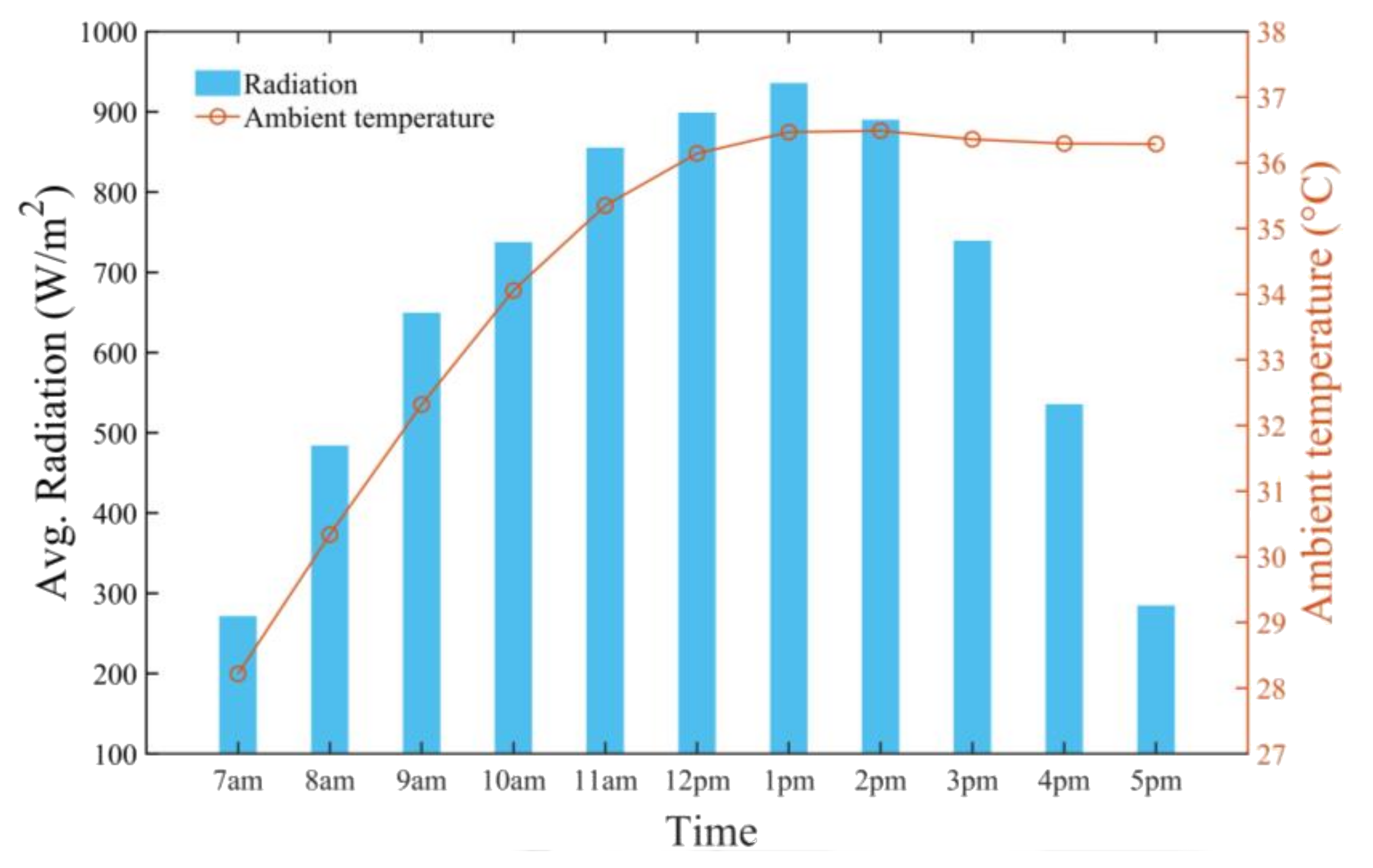
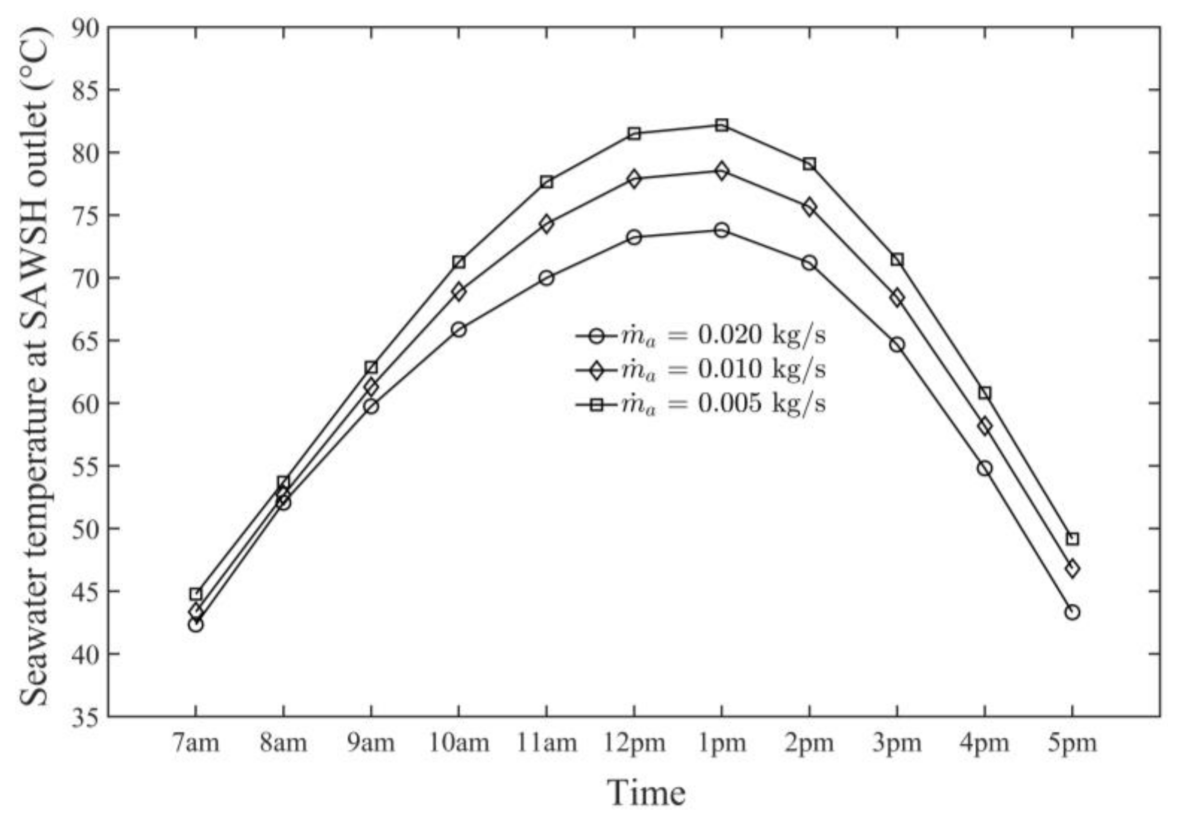
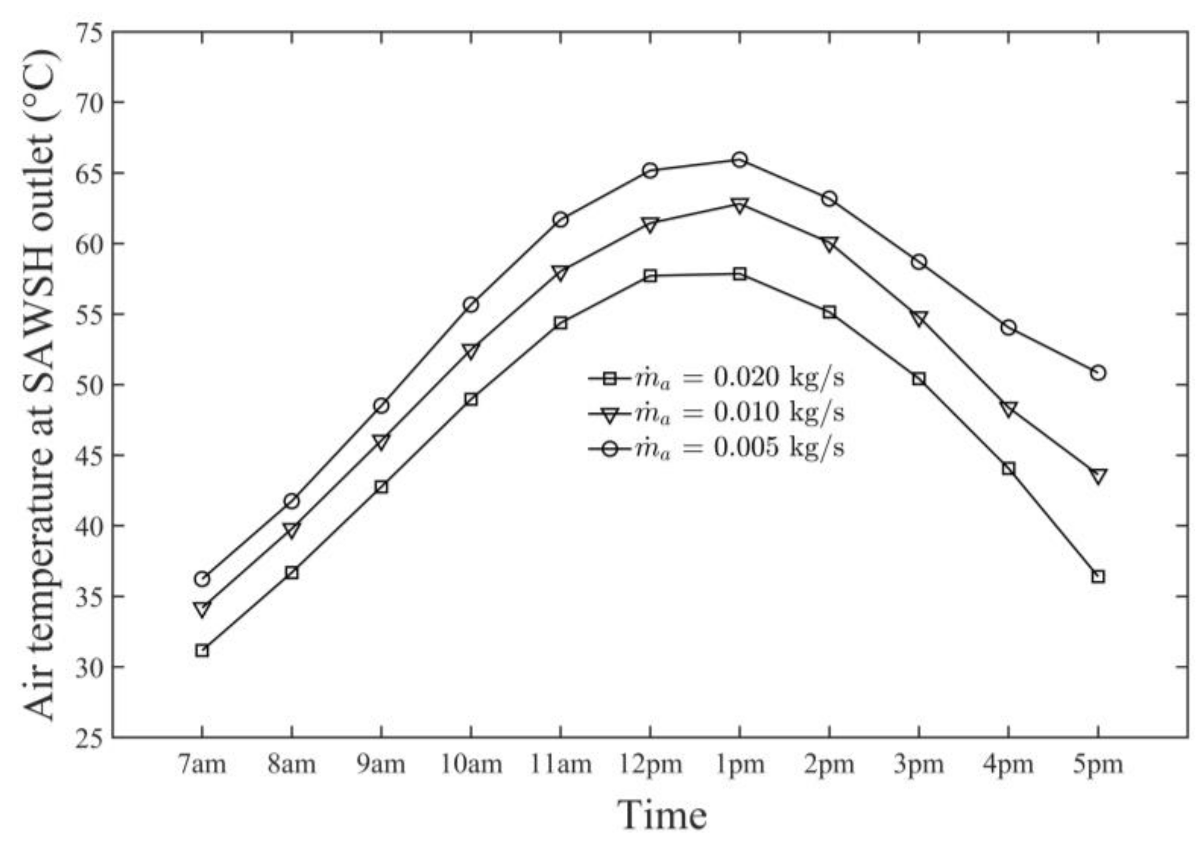
  • The average daily maximum air and seawater temperature values obtained by the SAWSH were 66 and 83 °C, respectively, on 21 June at 1 p.m.
  • The SAWSH-HDH system performed well at lower air mass flow rates. At mass flow rates of 0.005, 0.010, and 0.020 kg/s, the maximum air temperature values were 66, 62, and 57 °C, respectively, whereas the maximum seawater temperature values were 83, 78, and 73 °C, respectively.
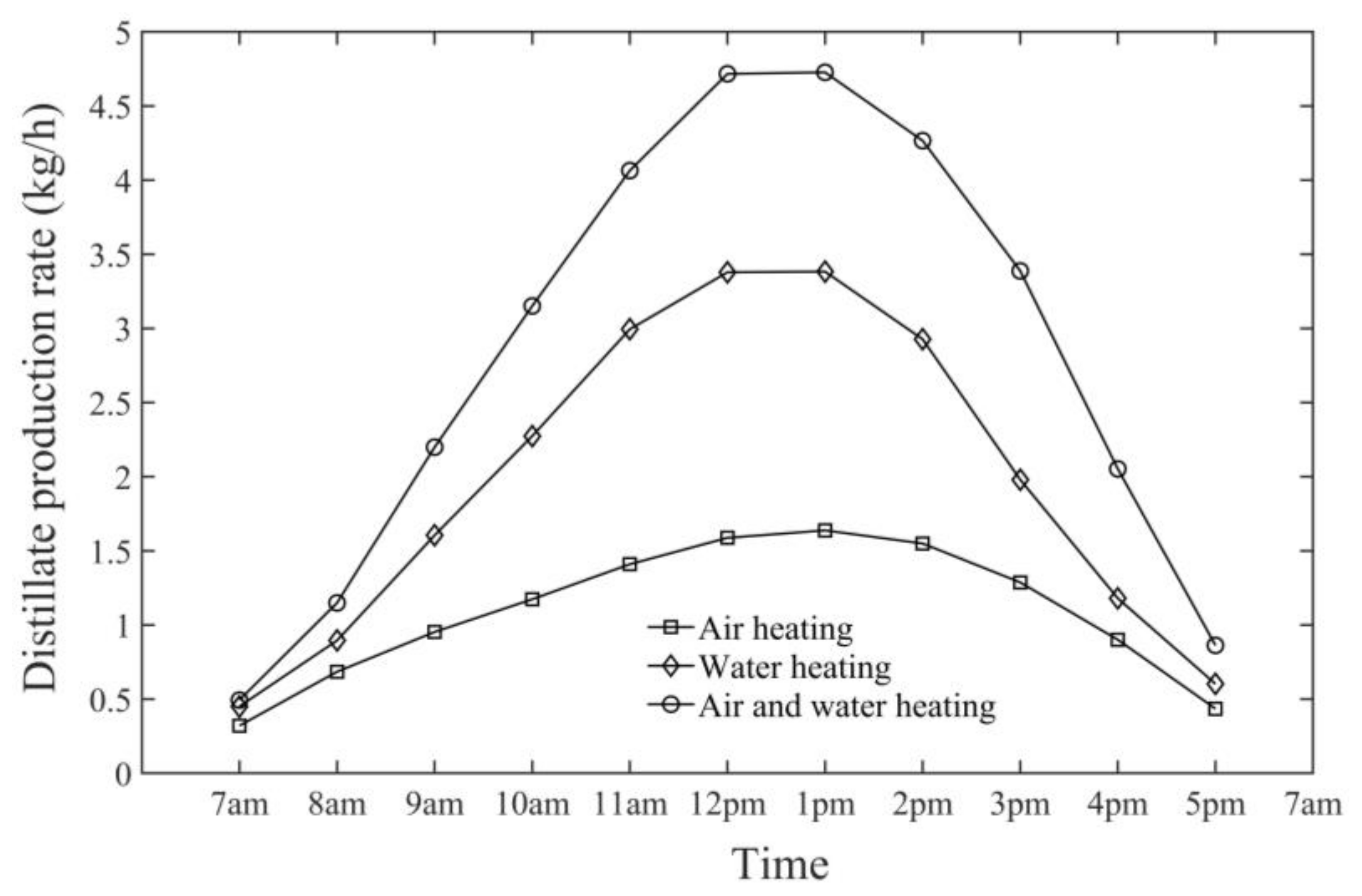
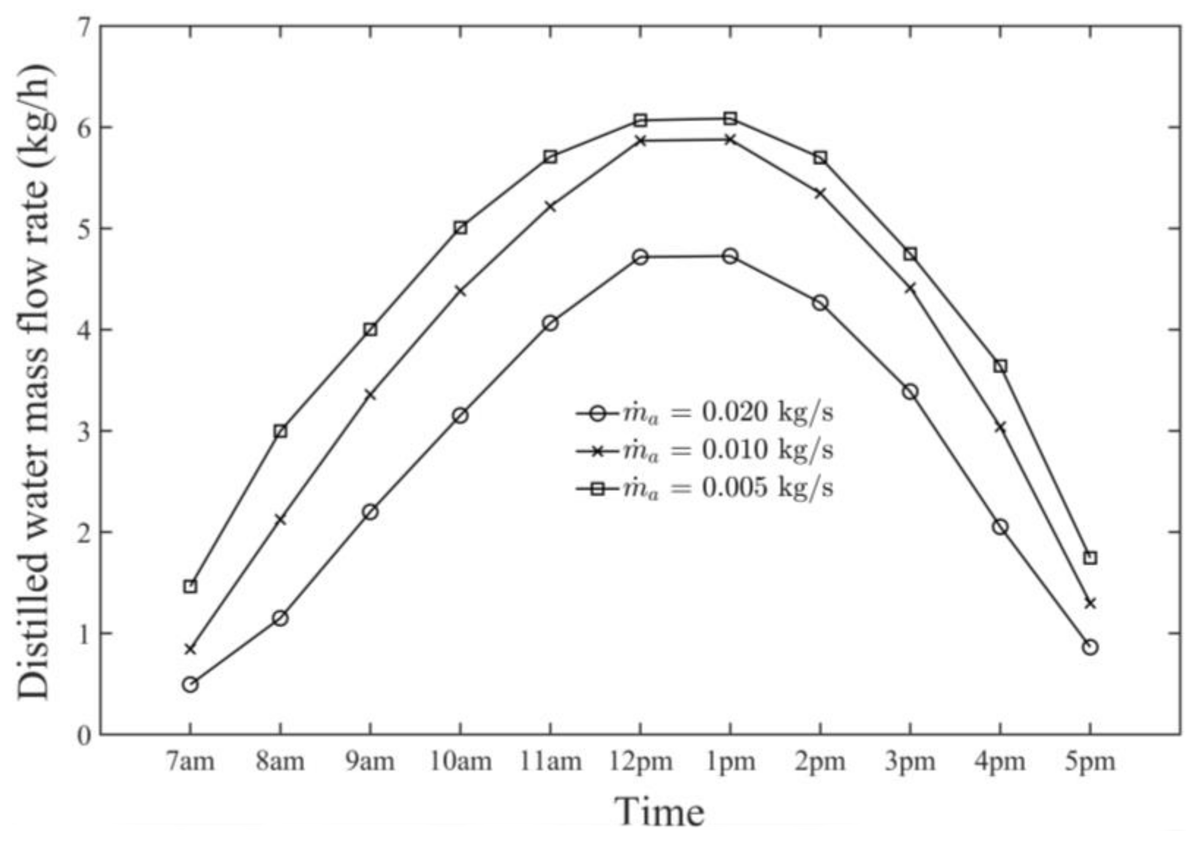
  • The observed hourly maximum productivity (i.e., distillate water production rate) from the HDH system was 6.20 kg/h at 1 p.m. on 21 June at an air mass flow rate of 0.005 kg/s.
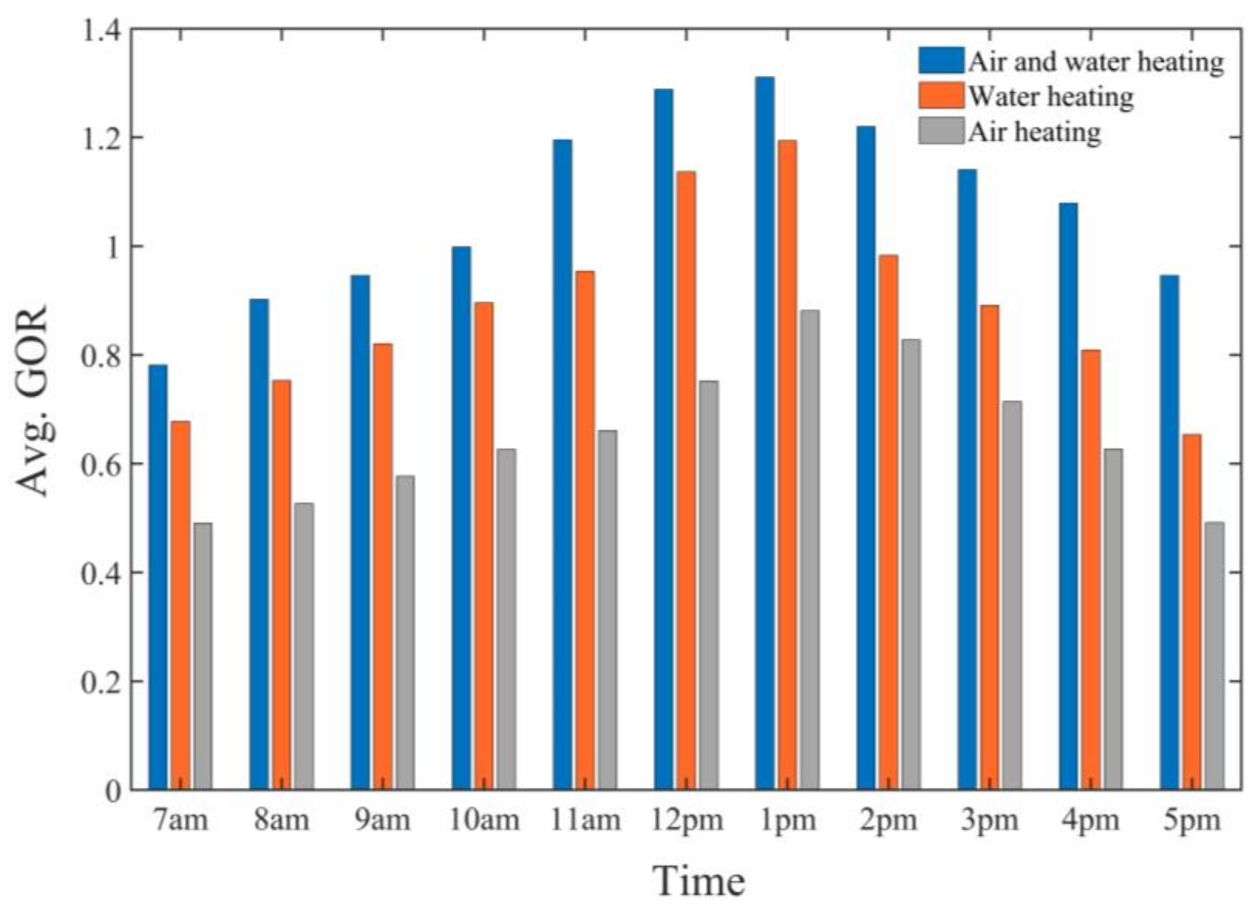
  • The comparison between air-heating and water-heating systems and the dual-fluid heating system demonstrated that the air-preheating system had lower performance in terms of productivity and GOR, the water-preheating system had higher productivity and GOR than the air-preheating system, and the dual-fluid heating system was more efficient than both systems in terms of productivity and GOR.
  • The observed highest monthly average air temperature and seawater temperature were 60 and 69 °C, respectively.
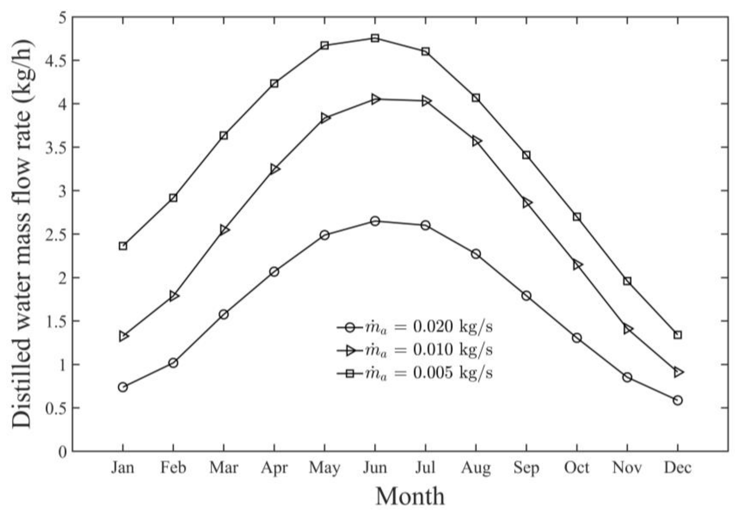
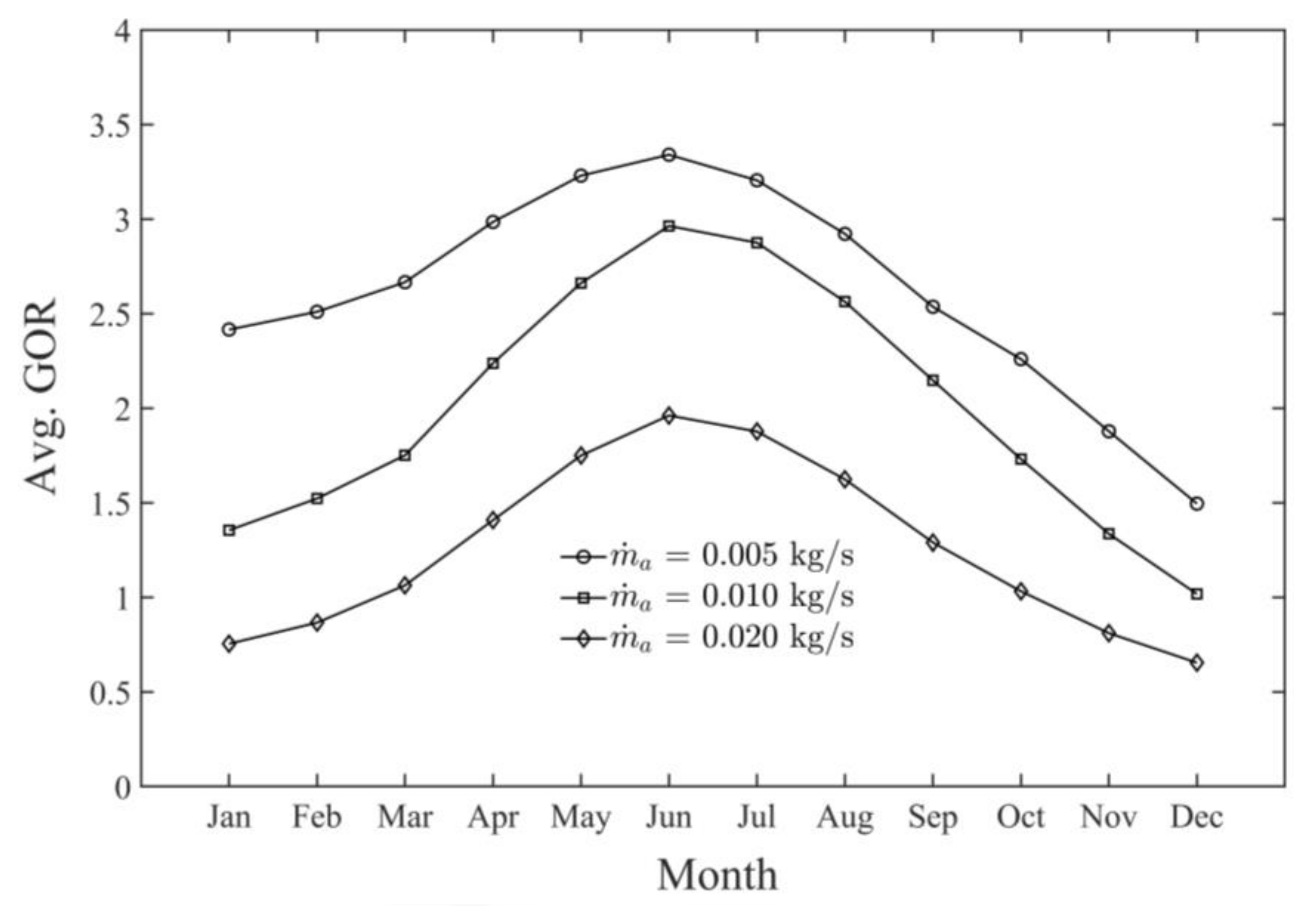
  • The highest monthly productivity and GOR of the SAWSH-HDH system for June were found to be 4.60 kg/h and 3.35 kg/h, respectively.
Thus, the use of SAWSH is highly recommended for simultaneously preheating air and seawater in the HDH desalination system to improve productivity. The use of the proposed SAWSH-HDH system in arid regions where solar energy is abundant is considerably feasible and cost effective for desalting seawater or brackish water throughout the year.

Author Contributions

Conceptualization, S.H.S. and Y.-D.K.; methodology, S.H.S. and Y.-D.K.; writing—original draft preparation, S.H.S., R.S., C.-U.B. and Y.-D.K.; writing—review and editing, S.H.S., R.S. and Y.-D.K.; supervision, Y.-D.K. and W.-S.K.; project administration, Y.-D.K. and W.-S.K.; funding acquisition, Y.-D.K. and W.-S.K. All authors have read and agreed to the published version of the manuscript.

Funding

This study was supported by the Korea Institute of Energy Technology Evaluation and Planning (KETEP) funded by the Ministry of Trade, Industry and Energy (MOTIE) of the Republic of Korea (No. 20194010201740).

Institutional Review Board Statement

Not applicable.

Informed Consent Statement

Not applicable.

Data Availability Statement

Not applicable.

Acknowledgments

The authors would like to acknowledge the support provided by Institute of Energy Technology Evaluation and Planning (KETEP) Ministry of Trade, Industry and Energy (MOTIE) of the Republic of Korea, and the research scholarship project of “HRD Initiative-MS leading to Ph.D. Program of Faculty Development for UESTPs/UETs (Batch-V)” funded by the Higher Education Commission (HEC) and Government of Pakistan.

Conflicts of Interest

The authors declare no conflict of interest.

Nomenclature

acCross-sectional area of upper compartment (air-heating channel) (m2)
apPerimeter of the upper compartment (m2)
ApArea of the absorber plate (m2)
AcolCollector area (m2)
cairSpecific heat capacity of air (1.009 kJ/kg °C)
cwSpecific heat capacity of seawater (4.193 kJ/kg °C)
cvSpecific heat capacity of water vapor (1.88 kJ/kg °C)
DeEquivalent diameter (m)
HaEnthalpy of air (kJ/kg)
HwEnthalpy of seawater (kJ/kg)
haapConvective heat transfer coefficient between air and plate (W/m2 °C)
hagcConvective heat transfer coefficient between air and glass cover (W/m2 °C)
hbaConvective heat transfer coefficient between bottom and air (W/m2 °C)
hgcaConvective heat transfer coefficient between glass cover and ambient air
(W/m2 °C)
hpwConvective heat transfer coefficient between plate and water (W/m2 °C)
hfgLatent heat of evaporation and condensation (kJ/kg)
hramRadiation heat transfer coefficient between glass cover and ambient air
(W/m2 °C)
hrpgcRadiation heat transfer coefficient between plate and glass cover
(W/m2 °C)
kairThermal conductivity of air (W/m °C)
KiThermal conductivity of insulation (W/m °C)
LLength of collector (m)
WWidth of collector (m)
m ˙ a Mass flow rate of air (kg/s)
m ˙ b Mass flow rate of brine (kg/s)
m ˙ c w Mass flow rate of cooling water (kg/s)
dMass flow rate of distilled water (kg/s)
m ˙ w Mass flow rate of seawater (kg/s)
MwMass of seawater in collector (kg)
MRMass ratio
NuNusselt number
PatmAtmospheric pressure (kPa)
PsSaturation pressure (kPa)
ReReynolds number
SSolar radiation intensity (W/m2)
sSalinity of seawater (kgsalt/kgseawater)
tiThickness of insulation (m)
T1Temperature of cooling water at inlet of dehumidifier (°C)
T2Temperature of cooling water at outlet of dehumidifier (°C)
T3Temperature of seawater at inlet of humidifier (°C)
T4Temperature of seawater at outlet of humidifier (°C)
T5Temperature of air at inlet of collector (°C)
T6Temperature of air at outlet of collector and inlet of humidifier (°C)
T7Temperature of air at outlet of humidifier and inlet of dehumidifier (°C)
T8Temperature of air leaving dehumidifier (°C)
TairTemperature of air flowing through upper compartment (°C)
TamAmbient temperature (°C)
TapTemperature of absorber plate (°C)
TbTemperature of base (°C)
TgcTemperature of glass cover (°C)
TwTemperature of seawater in lower compartment (°C)
UoOverall heat transfer coefficient between glass cover and ambient air
(W/m2 °C)
UbaOverall heat transfer coefficient between base and ambient air (W/m2 °C)
vairVelocity of ambient air (m/s)
Greek letters
αγγχAbsorptance of glass cover
ατEffective transmittance–absorptance product
εγχEmittance of glass

References

  1. Miletto, M. The United Nations World Water Development Report-Valuing Water; UNESCO: Paris, France, 2021. [Google Scholar]
  2. Santosh, R.; Arunkumar, T.; Velraj, R.; Kumaresan, G. Technological advancements in solar energy driven humidification–dehumidification desalination systems—A review. J. Clean. Prod. 2019, 207, 826–845. [Google Scholar] [CrossRef]
  3. Ahmed, F.E.; Hashaikeh, R.; Hilal, N. Solar powered desalination—Technology, energy and future outlook. Desalination 2019, 453, 54–76. [Google Scholar] [CrossRef] [Green Version]
  4. Giwa, A.; Akther, N.; Al Housani, A.; Haris, S.; Hasan, S.W. Recent advances in humidification dehumidification (HDH) desalination processes: Improved designs and productivity. Renew. Sustain. Energy Rev. 2016, 57, 929–944. [Google Scholar] [CrossRef]
  5. Alnaimat, F.; Ziauddin, M.; Mathew, B. A review of recent advances in humidification and dehumidification desalination technologies using solar energy. Desalination 2021, 499, 114860. [Google Scholar] [CrossRef]
  6. Rajaseenivasan, T.; Srithar, K. An investigation into a laboratory scale bubble column humidification dehumidification desalination system powered by biomass energy. Energy Convers. Manag. 2017, 139, 232–244. [Google Scholar] [CrossRef]
  7. Al-Sulaiman, F.A.; Zubair, M.I.; Atif, M.; Gandhidasan, P.; Al-Dini, S.A.; Antar, M.A. Humidification dehumidification desalination system using parabolic trough solar air collector. Appl. Therm. Eng. 2015, 75, 809–816. [Google Scholar] [CrossRef]
  8. Narayan, G.P.; Sharqawy, M.H.; Summers, E.K.; Lienhard, J.H.; Zubair, S.M.; Antar, M.A. The potential of solar-driven humidification-dehumidification desalination for small-scale decentralized water production. Renew. Sustain. Energy Rev. 2010, 14, 1187–1201. [Google Scholar] [CrossRef]
  9. Rahimi-Ahar, Z.; Hatamipour, M.S.; Ahar, L.R. Air humidification–dehumidification process for desalination: A review. Prog. Energy Combust. Sci. 2020, 80, 100850. [Google Scholar] [CrossRef]
  10. Mohamed, A.M.I.; Elminshawy, N.A.S. Theoretical investigation of solar humidification–dehumidification desalination system using parabolic trough concentrators. Energy Convers. Manag. 2011, 52, 3112–3119. [Google Scholar] [CrossRef]
  11. Khalil, A.; El-Agouz, S.A.; El-Samadony, Y.A.F.; Abdo, A. Solar water desalination using an air bubble column humidifier. Desalination 2015, 372, 7–16. [Google Scholar] [CrossRef]
  12. Yildirim, C.; Solmus, I. A parametric study on a humidification–dehumidification desalination unit powered by solar air and water heaters. Energy Convers. Manag. 2014, 86, 568–575. [Google Scholar] [CrossRef]
  13. Sharshir, S.W.; Peng, G.; Yang, N.; Eltawil, M.A.; Ali, M.K.A.; Kabeel, A.E. A hybrid desalination system using humidification–dehumidification and solar stills integrated with evacuated solar water heater. Energy Convers. Manag. 2016, 124, 287–296. [Google Scholar] [CrossRef]
  14. Antar, M.A.; Sharqawy, M.H. Experimental investigations on the performance of an air heated humidification–dehumidification desalination system. Desalin. Water Treat. 2013, 51, 837–843. [Google Scholar] [CrossRef]
  15. Dai, Y.J.; Wang, R.Z.; Zhang, H.F. Parametric analysis to improve the performance of a solar desalination with humidification and dehumidification. Desalination 2002, 142, 107–118. [Google Scholar] [CrossRef]
  16. Dai, Y.J.; Zhang, H.F. Experimental investigation of a solar desalination unit with humidification and dehumidification. Desalination 2000, 130, 169–175. [Google Scholar] [CrossRef]
  17. Houcine, I.; Amara, M.B.; Guizani, A.; Maalej, M. Pilot plant testing of a new solar desalination process by a multiple-effect-humidification technique. Desalination 2006, 196, 105–124. [Google Scholar] [CrossRef]
  18. Orfi, J.; Galanis, N.; Laplante, M. Air humidification–dehumidification for a water desalination system using solar energy. Desalination 2007, 203, 471–481. [Google Scholar] [CrossRef]
  19. Zhani, K.; Bacha, H.B. Experimental investigation of a new solar desalination prototype using the humidification dehumidification principle. Renew. Energy 2010, 35, 2610–2617. [Google Scholar] [CrossRef]
  20. Kabeel, A.E.; El Said, E.M.S. A hybrid solar desalination system of air humidification dehumidification and water flashing evaporation Part 1: A numerical investigation. Desalination 2013, 320, 56–72. [Google Scholar] [CrossRef]
  21. Yamali, C.; Solmus, I. Theoretical investigation of a humidification dehumidification desalination system configured by a double-pass flat plate solar air heater. Desalination 2007, 205, 163–177. [Google Scholar] [CrossRef]
  22. Nafey, A.S.; Fath, H.E.S.; El-Helaby, S.O.; Soliman, A.M. Solar desalination using humidification–dehumidification processes. Part I: A numerical investigation. Energy Convers. Manag. 2004, 45, 1243–1261. [Google Scholar] [CrossRef]
  23. Nafey, A.S.; Fath, H.E.S.; El-Helaby, S.O.; Soliman, A.M. Solar desalination using humidification–dehumidification processes. Part II: An experimental investigation. Energy Convers. Manag. 2004, 45, 1263–1277. [Google Scholar] [CrossRef]
  24. Rajaseenivasan, T.; Srithar, K. Potential of a dual purpose solar collector on humidification dehumidification desalination system. Desalination 2017, 404, 35–40. [Google Scholar] [CrossRef]
  25. Wu, G.; Zheng, H.; Ma, X.; Kutlu, C.; Su, Y. Experimental investigation of a multi-stage humidification–dehumidification desalination system heated directly by a cylindrical Fresnel lens solar concentrator. Energy Convers. Manag. 2017, 143, 241–251. [Google Scholar] [CrossRef]
  26. Xiao, J.; Zheng, H.; Jin, R.; Liang, S.; Wang, G.; Ma, X. Experimental investigation of a bubbling humidification–dehumidification desalination system directly heated by cylindrical Fresnel lens solar concentrator. Sol. Energy 2021, 220, 873–881. [Google Scholar] [CrossRef]
  27. Santosh, R.; Kumaresan, G.; Kumar, G.K.; Velraj, R. Experimental parametric investigation of waste heat powered humidification dehumidification system for production of freshwater from wastewater. Desalination 2020, 484, 114422. [Google Scholar] [CrossRef]
  28. Somwanshi, A.; Sarkar, N. Thermal performance of a dual-purpose collector-cum-storage type air-water heater. Appl. Therm. Eng. 2020, 171, 115094. [Google Scholar] [CrossRef]
  29. Mamouri, S.J.; Tan, X.; Klausner, J.F.; Yang, R.; Benard, A. Performance of an integrated greenhouse equipped with Light-Splitting material and an HDH desalination unit. Energy Convers. Manag. X 2020, 7, 100045. [Google Scholar] [CrossRef]
  30. Abbasi, O.A. Water desalination using renewable energy in a humidification-dehumidification cycle for Bahrain climate conditions. KnE Eng. 2018, 213–220. [Google Scholar] [CrossRef]
  31. Tiwari, G.N. Solar Energy Fundamentals, Design Modeling and Applications; Narosa Publishing House: New Delhi, India, 2002. [Google Scholar]
  32. Kays, W.M. Convective Heat and Mass Transfer; McGraw-Hill: New York, NY, USA, 1993. [Google Scholar]
  33. Sharqawy, M.H.; Antar, M.A.; Zubair, S.M.; Elbashir, A.M. Optimum thermal design of humidification–dehumidification desalination systems. Desalination 2014, 349, 10–21. [Google Scholar] [CrossRef]
  34. Chehayeb, K.M.; Narayan, G.P.; Zubair, S.M.; Lienhard, J.H.V. Use of multiple extractions and injections to thermodynamically balance the humidification–dehumidification desalination system. Int. J. Heat Mass Transfer 2014, 68, 422–434. [Google Scholar] [CrossRef] [Green Version]
  35. WHO. Guidelines for Drinking Water Quality, 4th ed.; World Health Organization (WHO): Valletta, Malta, 2011. [Google Scholar]
  36. Sharqawy, M.H.; Lienhard, J.H.V.; Zubair, S.M. Thermophysical properties of seawater: A review of existing correlations and date. Desalin. Water Treat. 2010, 16, 354–380. [Google Scholar] [CrossRef]
  37. Hermosillo, J.J.; Bulnes, C.A.A.; Estrada, C.A. Water desalination by air humidification: Mathematical model and experimental study. Sol. Energy 2012, 86, 1070–1076. [Google Scholar] [CrossRef]
  38. Hamed, M.H.; Kabeel, A.E.; Omara, Z.M.; Sharshir, S.W. Mathematical and experimental investigation of a solar humidification–dehumidification desalination unit. Desalination 2015, 358, 9–17. [Google Scholar] [CrossRef]
  39. Ali-Sahali, M.; Ettouney, H.M. Humidification dehumidification desalination process: Design and performance evaluation. Chem. Eng. J. 2008, 143, 257–264. [Google Scholar] [CrossRef]
  40. Ishida, K.; Ohara, N.; Kavvas, M.L.; Chen, Z.Q.; Anderson, M.L. Impact of air temperature on physically based maximum precipitation estimation through change in moisture holding capacity of air. J. Hydrol. 2018, 556, 1050–1063. [Google Scholar] [CrossRef]
  41. Perry, R.H.; Green, D. Chemical Engineers Handbook, 6th ed.; McGraw-Hill: New York, NY, USA, 1984; pp. 12–13. [Google Scholar]
  42. Sea Temperature Meteorological Services. Available online: https://seatemperature.net/ (accessed on 20 March 2021).
  43. The National Renewable Energy Laboratory NREL (USA). Available online: https://www.nrel.gov/grid/solar-resource/saudi-arabia.html (accessed on 22 March 2021).
Figure 1. Humidification–dehumidification desalination powered by SAWSH.
Sustainability 13 13491 g001
Figure 2. Schematics of SAWSH depicting (a) top view and (b) front view.
Sustainability 13 13491 g002
Figure 3. SAWSH-HDH in (a) air-heating and (b) water-heating modes.
Sustainability 13 13491 g003aSustainability 13 13491 g003b
Figure 4. Trend of solar radiation and ambient temperature (21 June 2020, Jeddah, Saudi Arabia).
Sustainability 13 13491 g004
Figure 5. Distillate production rate comparison between water-heating, air-heating, and air–water-heating systems at air and water mass flow rates of 0.020 and 0.029 kg/s.
Sustainability 13 13491 g005
Figure 6. GOR comparison between water-heating, air-heating, and air-water-heating HDH systems.
Sustainability 13 13491 g006
Figure 7. Variation in seawater temperature at SAWSH outlet with respect to air mass flow rate.
Sustainability 13 13491 g007
Figure 8. Variation in air temperature at SAWSH outlet with respect to air mass flow rate.
Sustainability 13 13491 g008
Figure 9. Distilled water mass flow rates on 21 June 2020 at different air mass flow rates.
Sustainability 13 13491 g009
Figure 10. Monthly average solar radiation and ambient temperature.
Sustainability 13 13491 g010
Figure 11. Variation in monthly outlet air temperature with different air mass flow rates.
Sustainability 13 13491 g011
Figure 12. Variation in monthly outlet seawater temperature at various air mass flow rates.
Sustainability 13 13491 g012
Figure 13. Distillate rate for different months at various air mass flow rates.
Sustainability 13 13491 g013
Figure 14. Monthly averaged GOR versus various air mass flow rates at seawater mass flow rate of 0.029 kg/s and component effectiveness of 85%.
Sustainability 13 13491 g014
Figure 15. Validation of current study with experimental work [28] considering (a) water temperature and (b) air temperature.
Sustainability 13 13491 g015
Figure 16. Performance comparison between results of modeled HDH system and Sharqawy et al. [33].
Sustainability 13 13491 g016
Table 1. Dimensions and process parameters of SAWSH [28].
ParameterValue
Mass of seawater in collector at any instance (Mw)105 kg
Area of absorber plate (Ap)1.5 m2
Length of collector (L)1.5 m
Stefan’s constant (σ)5.67 × 10⁻⁸ W/m2 °C4
Absorptance–transmittance product (ατ)0.85
Absorptance of glass cover (αgc)0.05
Emissivity of absorber plate (εp)0.85
Heat transfer between water and plate (hpw)108.6 W/m2 °C
Density of air (ρair)1.2 kg/m3
Thermal conductivity of insulation (Ki)0.004 W/m °C
Insulation thickness (ti)0.05 m
Cross-section of upper compartment (air channel) (C)1.5 m2
Air mass flow rate across SAWSH ( m ˙ a i r )0.005, 0.010, and 0.020 kg/s
Table 2. Coefficients considered for seawater enthalpy calculation [36].
a1−2.348 × 10⁴a6−44.17
a23.15 × 105a72.139 × 10−1
a32.803 × 106a8−1.997 × 10⁴
a4−1.446 × 10⁷a92.778 × 104
a57.826 × 103a1097.28
Publisher’s Note: MDPI stays neutral with regard to jurisdictional claims in published maps and institutional affiliations.

