Abstract
The installation and operation of enhanced geothermal systems (EGS) involves many challenges. These challenges include the high cost and high risk associated with the investment capital, potential large working-fluid leakage, corrosion of equipment, and subsiding land. A super-long heat pipe can be used for geothermal exploitation to avoid these problems. In this paper, a high aspect-ratio heat pipe (30 m long, 17 mm in inner diameter) is installed vertically. Experiments are then carried out to study its heat-transfer performance and characteristics using several filling ratios of deionized water, different heating powers, and various cooling-water flowrates. The results show that the optimal filling-ratio is about 40% of the volume of the vaporizing section of the heat pipe. Compared with a conventional short heat pipe, the extra-long heat pipe experiences significant thermal vibration. The oscillation frequency depends on the heating power and working-fluid filling ratio. With increasing cooling-water flow rate, the heat-transfer rate of the heat pipe increases before it reaches a plateau. In addition, we investigate the heat-transfer performance of the heat pipe for an extreme working-fluid filling ratio; the results indicate that the lower part of the heat pipe is filled with vapor, which reduces the heat-transfer to the top part. Based on the experimental data, guidelines for designing a heat pipe that can be really used for the exploitation of earth-deep geothermal energy are analyzed.
1. Introduction
A heat pipe is a highly-efficient heat-transfer device that uses liquid-to-vapor phase change and the associated fluid flow to transfer heat from a hot to a cold region. The concept of a heat pipe was first suggested by Gaugler at the Los Alamos National Laboratory in 1942. The sealed Perkins tube, which was patented in the United Kingdom by Jacob Perkins (1836), had a structure that was most similar to a modern gravity-assisted heat pipe—a thermosyphon [1]. In contrast with highly-conductive materials such as copper, heat pipes can be designed to move larger quantities of heat over longer distances, through narrower spaces, and using lower temperature differences [2]. The effective thermal conductivity can approach 100 kW/(m·K) for long heat pipes, compared to approximately 0.4 kW/(m·K) for copper. Usually, the heat pipe consists of a closed structure, which is filled with a working-fluid in two phases. Since the liquid and its vapor coexist in equilibrium, the pressure inside the container is equal to the vapor pressure that corresponds to the saturation condition [3]. Due to its extraordinary heat transfer performance, there are many applications for heat pipes such as electronic device cooling [4,5,6,7], spacecraft temperature equalization [8], renewable energy exploitation [9,10,11], preservation of permafrost [12], snow melting, and de-icing [13].
Here, we focus on renewable energy exploitation application because the increase in global energy demand and global climate change due to the utilization of fossil fuels. Geothermal energy, an important kind of renewable energy, has ample supply, is clean and can provide a stable supply of power. Main barriers for large scale commercialization of geothermal technology lie in finding the proper location and developing effective technology for heat extraction [14]. Geothermal energy can be divided into three different types: shallow geothermal, hydrothermal, and hot dry rock [15]. Among them, shallow geothermal and hydrothermal have mature and low-cost exploitation technologies. Hot dry rock, generally buried 3–10 km deep underground and containing no or very little water, is a kind of widely distributed and abundant geothermal resources [15]. It has attracted much attention in recent years. However, up to date it still lacks an effective method that is relatively inexpensive and technically mature (low risk) to mine heat from hot dry rock.
Heat pipe as an efficient heat-transfer device can be used for hot dry rock geothermal exploitation. There are many advantages of using heat pipes, especially gravity-assisted heat-pipes, e.g., simple fabrication and operation, low cost, and high heat-transfer efficiency [16,17]. For a gravity-assisted heat pipe when used for hot dry rock thermal energy extraction, the liquid in the lower part of the heat pipe, i.e., the vaporizing section, is heated and vaporizes by the thermal energy of hot dry rock; the pressurized vapor flows upward to the condensation/condenser section, which is located above the ground surface; then, the vapor condenses inside the condensation section and the liquid returns back (due to gravity) to the lower vaporization section. This procedure repeats and the heat in the rock is continuously moved to the surface of the ground, where it becomes available for the conversion to electricity or to be used in buildings (for room heating) directly. This hot dry rock heat-mining method does not require pump-power to circulate the fluid during the process, which makes the system less costly in operation. In addition, only heat is transferred and no ground water is involved, which bypasses some conventional geothermal disadvantages such as subsiding land and water-contamination [18].
Until now, most gravity-assisted heat pipes, which were reported in the literature, focused on heat pipes that are not longer than 10 m. However, to use heat pipes for deep geothermal energy-exploitation, the heat pipe length needs to exceed at least 1000 m. The length-to-diameter ratio is as high as several—or even ten—thousands. Hence, the traditional empirical formula based on conventional heat-pipe studies may not be suitable for extra- or super- long gravity-assisted heat pipes. There are very few investigations of the thermal energy exploitation of hot dry rock with super-long heat pipes [19]. Most of the geothermal studies related to heat pipes focus on shallow geothermal energy exploitation. For example, in very cold regions, gravity-assisted heat pipes, which are buried below the road, can protect the road from snow cover [13]. Gravity-assisted heat pipes are also used for frozen earth projects. For the Qinghai-Tibet Railway in China, for example, gravity-assisted heat pipes are used to keep the tundra stable [12]. In petroleum engineering, gravity-assisted heat-pipes are placed inside a wellbore to let the heat at the bottom reach the top, which acts similar to a wellbore heating method. Field tests showed that gravity-assisted heat pipes could reduce wellbore heat loss and extend the oil production duration [20]. The heat pipes in the above examples show a heat-transfer capacity below 50 kW. Kusaba et al. [21] developed a 150 m long, large-scale heat pipe, with a 150 mm diameter, in which liquid feeding-tubes with showering nozzles were installed. A test was carried out for well temperatures between 100 and 150 °C at a geothermal site in Kyushu, Japan. The heat pipe extracted 90 kW heat at a working temperature of 80 °C. Jiang et al. [22] proposed, for the first time, a design that allows mining heat from earth-deep hot dry rock by using a heat pipe. In 2020, a field test using a super-long gravity heat pipe to extract the hot dry rock heat was conducted in Tangshan, Province Hebei, China. In this field test, a 3000-meter heat pipe was installed in a geothermal deep well and the underground rock around the heat pipe evaporation section has an average temperature of 119 °C. Without any reservoir engineering, the heat pipe can steadily produce heat power approximately 200 kW, and the highest temperature of water vapor got in the ground condenser is about 90 °C [23,24,25]. It is the first successful implementation of kilometer-level heat pipe in geothermal energy production.
In this paper, we self-build a test-setup of a gravity-assisted heat-pipe with large length-to-diameter ratio. A series of experiments are carried out to investigate the heat pipe’s heat transfer performance and working characteristics. Based on the results obtained from the laboratory-scale tests, we attempt to analyze the guideline for designing a super-long heat pipe that can be used to extract hot dry rock thermal energy.
2. Experimental
2.1. Test Setup
To study the heat-transfer performance of a large length-to-diameter-ratio gravity heat pipe, a long and thin heat pipe, which consists of a single copper tube, was installed vertically—see Figure 1. In the experiment, the outer diameter of the heat pipe is 19 mm, the inner diameter is 17 mm, the length is 30 m, and the length-to-inner diameter ratio is as high as 1765. The heating section is 4.6 m long, the condensation section 4.3 m, and the adiabatic section 21.7 m. The long heat pipe is empty inside. The heat pipe dimensions are large enough to avoid significant capillary effect in the pipe, and small enough to have big length-to-inner diameter ratio comparable to real geothermal application scenarios. In terms of the length-to-inner diameter ratio, the experimental heat pipe is equivalent to the real geothermal heat pipe of 353 m in length and 200 mm inner diameter.
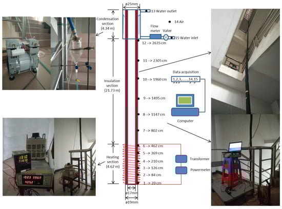
Figure 1.
Photos and a schematic diagram of the super-long gravity heat-pipe test setup.
The test setup consists of a heating system, adiabatic system, condenser system, and a temperature-data acquisition system. The heating system consists of heater strips that are wound around the lower part of the heat pipe. The heating power is controlled by regulating a transformer and monitored by a power-meter. The condensation section comprises a hose with an inner diameter of 25 mm and outer diameter of 30 mm, set at the top part (outside) of the heat pipe to act as a coaxial tube-heat exchanger. Tap water is used to cool the heat pipe. The surface of the heat pipe is covered with adiabatic material. The middle part of the heat pipe acts as the thermal insulation section.
To study the operation characteristics of the super-long heat pipe, 15 temperature measurement points are used along the heat pipe to monitor temperature changes. Among these, points (thermocouples) 1–6 measure the temperature of the evaporation section, points 7–12 measure the adiabatic section temperature, point 13 the cooling-water inlet temperature, point 14 the air temperature, point 15 the cooling-water outlet temperature. Computer and data acquisition equipment collects the temperature data with a sampling rate of 1 Hz. To make the condensation section full with cooling-water, the cooling-water inlet is at the bottom of the section and the outlet at the top (see Figure 1). The temperatures are measured with K-type thermocouples with an error of ±0.3 °C. The cooling-water flowrate in the condenser is measured using a rotameter with an error of ±0.1 mL/s. The heating power is measured with a digital power-meter (0–12 kW) with an uncertainty of ±1% FS (Full Scale).
2.2. Experimental Procedure
In the experiment, deionized water is used as working-fluid for the super-long heat pipe. The heat pipe was first evacuated before a certain volume of deionized water was sucked in. Subsequently, it was evacuated a second time to remove any remaining non-condensable gas after the working fluid water was filled in and the heat pipe was in operating. Four experimental procedures were carried out to study the heat-transfer performance and characteristics of the super-long heat pipe: (i) At a fixed heating-power and cooling-water flowrate, the heat pipe was tested with different working-fluid filling volumes to find the optimal fill-ratio. (ii) At a fixed heating-power and a certain working-fluid filling volume, the heat pipe was tested with different cooling-water flowrates. (iii) At extreme working-fluid filling volume and a certain cooling-water flow rate, the heat pipe was tested with different heating-powers. (iv) At a certain working-fluid filling volume and cooling-water flowrate, the heat pipe was tested with different heating powers to investigate the temperature oscillation characteristics.
3. Experimental Results and Analysis
3.1. Energy Balance Analysis
When heat pipe is in its stable working state, the heat input by heater strips (Qtotal ) can be divided into four parts, i.e.,
where, Q is the heat pipe heat-transfer rate that is absorbed by the cooling water and can be calculated using Equation (2).
Here, C is the specific heat of water, M is cooling-water flowrate, T13 and T15 represent the cooling-water temperatures at the inlet and outlet of the condenser (shown in Figure 1), respectively.
Qloss,1–3 in Equation (1) are the heat losses to the air in the heating, insulation and condensation sections of the heat pipe, respectively. For a tube with diameter D, wrapped with thermal insulation layer of a thickness δ, the heat loss of unit length qloss is calculated to be:
where, h is the convective heat transfer coefficient, is heat conductivity coefficient of the wrapped thermal insulation layer, Tin and Tout are the temperatures at the inner and outer walls of the thermal insulation layer, respectively. From Equation (3), we further deduce that
Therefore, heat losses at the heating, insulation and condensation sections of the heat pipe are
Here, i = 1–3.
In the experiments, a typical working condition is of heating power Qtotal = 1000 W, cooling water mass flow rate M = 6 mL/s, heat pipe water filling volume 400 mL. The heat conductivity coefficient of the insulating material is 0.04 W·m−1·K−1; the natural convective heat transfer coefficient h = 30 W·m−2·K−1 is adopted. Based on the 15 temperatures (in Figure 1, points 1–15) measured, we obtain Q = 738.2 W, Qloss,1 = 51.1 W, Qloss,2 = 177.1 W, Qloss,3 = 33.6 W through Equations (1)–(5). Most of the heat loss is from the heat pipe insulation section. Qtotal − Qloss,1 − Qloss,2 = 771.8 W, which means the heat pipe effectively transfers about 771.8/948.9 = 81.3% of the heat absorbed by its heating section to its condensation section.
3.2. Heat-Transfer Performance for Different Working-Fluid Filling Volumes
3.2.1. Optimal Working-Fluid Filling Volume
Figure 2 shows the heat pipe’s heat-transfer performance for different working-fluid filling volumes. The cooling-water flow rate is fixed at 5.5 mL/s. When the filling volume is about 400 mL, the heat pipe’s heat-transfer performance is always the best among the different measured heating-powers. In addition, Figure 2 shows that the higher the heating power is, the bigger is the heat-transfer rate of the heat pipe. In addition, when the working-fluid filling volume is 2500 mL, the heat pipe’s heat-transfer rate decreases remarkably. Furthermore, when the working-fluid filling volume is 5000 mL, the heat pipe does not work at all.
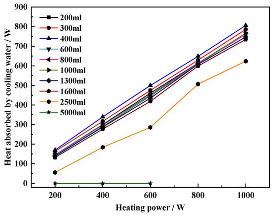
Figure 2.
Heat-transfer performance of heat pipes with different degrees of liquid filling (cooling-water flow rate: 5.5 mL/s).
Table 1 specially presents the results of three tests. Three filling volumes are tested with very small environmental differences. In all the three tests, the cooling-water flow rate is 5.5 mL/s, heating power is 800 W. Among these, the heat pipe has the highest heat-transfer rate when the filling volume is 400 mL. In the tests, the total volume of the heating section, i.e., the evaporation section, is 1000 mL. As a result, the optimal working-fluid filling ratio is 40%.

Table 1.
Heat-transfer performance of heat pipes with different degrees of liquid filling (heating power: 800 W, cooling-water flow rate: 6 mL/s).
The thermal resistance of the heat pipe is defined as:
Here, R is the thermal resistance of the heat pipe, Q is the heat-transfer rate, Theat is the heating temperature, T13 is the cooling-water outlet temperature. Table 1 shows that, when the filling volume is 400 mL, the thermal resistance of the heat pipe is the lowest. In the test, the total volume of the heating section, i.e., the evaporation section, is 1000 mL. Again, the optimal working-fluid filling ratio is 40%, at which the heat pipe shows the best heat transfer performance.
3.2.2. Analysis of the Results
To find out why different working-fluid filling volumes leads to different heat-transfer rates, a specific set of data, with heating power of 600 W, cooling-water flow rate of 5.5 mL/s, filling volumes range from 200 mL to 5000 mL, is obtained and analyzed.
An obvious cause is that different filling volumes result in different depths of water columns inside the vertical heat pipe. Different depths of water column cause different hydrostatic pressures. Table 2 shows the different depths of water column and heat-transfer rates at different working-fluid filling volumes. It appears that, with increasing filling volume, the depth of the water column increases naturally. The heat-transfer rate increases first and decreases after exceeding the optimal filling volume (about 400 mL).
Table 2.
Theoretical evaporation temperature and actual evaporation temperature (heating power: 600 W, coolant water circulating flow rate: 5.5 mL/s).
Thermodynamically, a working-fluid’s evaporation temperature corresponds to its pressure state. The working-fluid’s pressure is determined by two components: the first is the static pressure from gravity; the second is the vapor pressure in the adiabatic section. The pressure in the adiabatic section is equal to water saturation pressure of the two-phase water-vapor flow. To confirm that the evaporation temperature was determined by the pressure’s two components, we theoretically analyze the experimental data (see Table 2). This table lists both the measured evaporation temperatures and the calculated values. The hydrostatic pressure is calculated using the static pressure equation (p = ρgh) using the depth of the water column. The saturation pressure of the adiabatic section is calculated according to the measured temperature at the adiabatic section. The actual evaporation temperature takes the mean temperature of the heat pipe evaporation section. The calculated theoretical evaporation temperatures correspond well with the actual evaporation temperatures for the heat pipe with different working-fluid filling ratios. Figure 3 shows a comparison of the theoretical evaporation temperature and the actual evaporation temperature. The heating power is 600 W and the coolant water circulating flow rate is 5.5 mL/s.
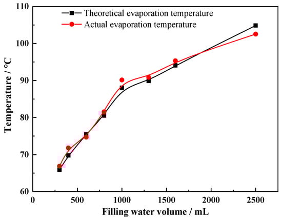
Figure 3.
Comparison between the theoretical evaporation temperature and actual evaporation temperature (heating power: 600 W, coolant water circulating flow rate: 5.5 mL/s).
It is seen from Figure 3 that the evolution of the theoretical evaporation temperature follows the actual evaporation temperature closely. Hence, the filling ratio of working-fluid is key to the heat-transfer performance of the super-long heat pipe. In addition, during operation, the working-fluid in the heat pipe evaporation section is not static, but dynamic. When the heat pipe is in operating, drastic boiling occurs inside the evaporation section. Due to the slim shape of the tube, bubbles push liquid upward and clean the inside wall of the heat pipe. When the heat pipe has an optimal filling volume of working-fluid, which can ensure the heat pipe evaporation section is sufficiently wetted, the evaporation temperature will not be too high. When the heat pipe is filled with less working-fluid, even though its evaporation temperature is low, liquid cannot wet the inside wall of the evaporation section completely. When the heat pipe is filled with too much working-fluid, even though the entire inner surface of the wall of the heat pipe evaporation section is covered by liquid, the evaporation temperature will be very high due to the large hydrostatic pressure.
Based on the above analysis, the main factors that affect the heat-transfer performance are evaporation temperature and inner wall wetting of the heated section. Figure 4 shows the temperature evolution for the heat pipe with different liquid filling volumes. When the working-fluid does not fill the whole heated section completely, see Figure 4a,b, the mean evaporation temperature is low. On the other hand, when the filling volume is high, see Figure 4c, the evaporation temperature is high and the heat-transfer rate is reduced.
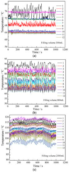
Figure 4.
Temperature vs. time curve for each measurement point for different liquid filling volumes (Liquid filling volume: (a) 300 mL, (b) 800 mL, (c) 2500 mL; Heating power: 1000 W; Cooling-water flow rate: 5.5 mL/s; 1–12 are measuring points indicated in Figure 1).
In addition, as shown in Figure 4, the temperatures at points 1~6 fluctuate considerably. This may be because when liquid from the condensation section enters the evaporation section, the temperature in the evaporation section decreases before it increases again. This process repeats constantly. Temperature fluctuation in the adiabatic section also occurs due to falling liquid from the condensation section and being heated again by hot vapor from the evaporation section.
3.3. Operation at Extreme Filling Volumes
Figure 5 shows the temperature evolution for the heat pipe with high filling volumes and different heating powers. It suggests that the extra-long heat pipe fails to transfer heat to the condensation section regardless of the input heating power. The temperature in the evaporation section is much higher than that for the optimal filling volume, and it fluctuates for moderate heating-power (see Figure 5a,b). The temperature decreases considerably along the heat pipe from evaporation section to condensation section. The temperature at point 12 is very close to the cooling water temperature. As a result, very small amount of heat is transferred to the condensation section and cooling-water temperature little increases.
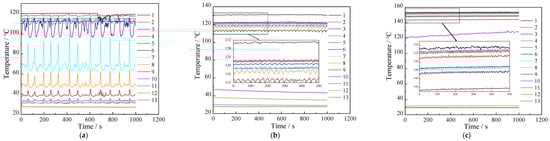
Figure 5.
Curve for the heat pipe at different heating powers with extremely large filling volume: 5000 mL. (Heating power: (a) 200 W, (b) 400 W, (c) 600 W; Cooling-water flow rate: 5.5 mL/s; 1–13 are measuring points indicated in Figure 1).
When the heat-pipe temperature has stabilized—see Figure 5c—we opened the top part of the heat pipe suddenly and observed the following: Liquid working-fluid gushed out immediately and no liquid remaining falls back to the bottom of the long heat pipe. This phenomenon indicates that when the heat pipe is heated with enough power, a stable column of gas appeared at the bottom of the heat pipe and pushes liquid upward. Upon constant heating, a gas column is sustained, and the liquid cannot fall back into the heated section. In addition, the fluid volume is large enough to fill the condensation section completely, and hot vapor cannot enter the condensation section. This phenomenon may be called entrainment limit and condenser flooding [1]. Furthermore, the temperature fluctuation in Figure 5a is larger than that in Figure 5b, and there is almost no temperature fluctuation visible in Figure 5c at all. Especially, for the temperature at point 11, Figure 5c (heating power = 600 W) is smaller than in Figure 5b (heating power = 400 W). This occurred because a gas column with higher pressure formed in the case (Figure 5c) with higher heating power, which causes the liquid to stay at the top of the heat pipe more stably, and heat is harder to transfer through it. A comparison between Figure 5a–c indicates that the higher the heating power is, the more stable is the gas column.
In Figure 5, the highest heating power is 600 W. During the experiments, we have actually tried higher heating power, the heat pipe does not work still except higher temperatures are measured at the heating section. We speculate that because of the large liquid filling volume, the condensation section is fully occupied by liquid water, and the more heating power, the higher pressure needs to hold liquid upward and the liquid cannot return to the heating section. It is the dry-out heating section and the higher pressure that cause the temperature further rise at the heat pipe heating section.
Figure 6 shows the temperature evolution for the heat pipe, when heating is stopped after heating with 600 W (stable condition)—see Figure 5c case. After heating stopped, the hot gas column at the lower part of the heat pipe cannot be maintained and liquid drops due to a reduced temperature in the evaporation section. Substantial boiling occurred immediately and the sound of an explosion is heard from the heat pipe. The temperatures throughout the heat pipe fluctuate by a large amplitude and decrease gradually. After 5900 s (see Figure 6), the temperature in the adiabatic section changes substantially. This indicates that heat-transfer into that section takes place. This also confirms the explanation for why the heat pipe does not work for extremely large water filling.
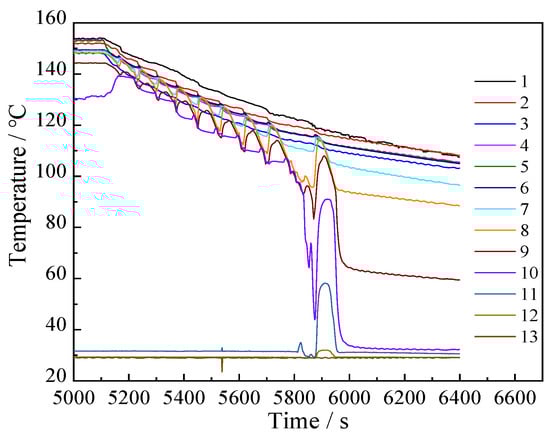
Figure 6.
Temperature evolution for the heat pipe when the heating power was stopped after 600 W heating (filling volume: 5000 mL; cooling-water flow rate: 5.5 mL/s; 1–13 are measuring points indicated in Figure 1).
3.4. Heat-Transfer Performance at Different Cooling-Water Flow Rates
Previous sections show that a suitable filling volume is about 400 mL. Figure 7 shows the heat-transfer performance for the heat pipe at different cooling-water flow rates with a filling volume of 400 mL and heating power of 800 W. The figure also shows that, with increasing cooling-water flow rate, the heat-transfer rate increases and reaches a plateau gradually, and the cooling-water outlet temperature decreases.
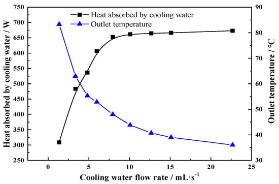
Figure 7.
Heat-transfer performance of heat pipes with different cooling-water flow rates (filling volume: 400 mL, heating power: 800 W).
Figure 8 shows the evolution of both the evaporation section temperature and adiabatic section temperature with increasing cooling-water flow rate. The figure indicates that both temperatures decrease and flatten out gradually with increasing cooling-water flow rate. Here, the filling volume is constant and consequently the hydrostatic pressure too. When cooling-water flow rate increases, the adiabatic section’s temperature decreases and the corresponding saturated pressure decreases too. Then, the evaporation temperature decreases and the heat-transfer rate increases as discussed in the previous section because the evaporation temperature is determined by the hydrostatic pressure as well as the saturated vapor pressure in the adiabatic section. In other words, the cooling-water flow rate affects the heat-transfer rate through changing the adiabatic section temperature.
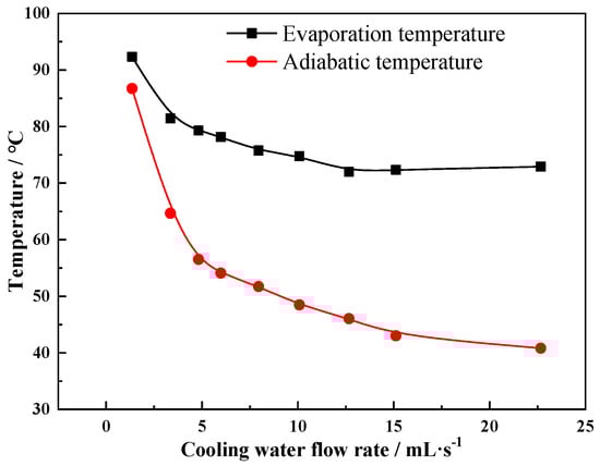
Figure 8.
Temperature in the evaporation and the adiabatic section as a function of the cooling-water flow rate (filling volume: 400 mL, heating power: 800 W).
From Figure 7 and Figure 8, it is seen that the lowered cooling water flow rate causes higher evaporation temperature, higher adiabatic temperature, and higher cooling water outlet temperature. Though the cooling water outlet temperature rises, due to the lowered mass flow rate, the heat pipe heat transfer rate that is the heat absorbed by the cooling water is reduced (Equation (2)). The heating power is fixed (i.e., 800 W) for all the tests in relation with Figure 7 and Figure 8. The increased heat pipe working temperature means more heat loss to environment. For example, in the test of the smallest cooling water flow rate, 1.35 mL/s, the evaporation temperature is high, about 92.3 °C and the adiabatic section temperature is 86.7 °C. According to Equations (4) and (5), the heat losses from the evaporation section and adiabatic section are 74.9 W and 321.8 W, respectively. That is, only (800 − 74.9 − 321.8)/(800 − 74.9) = 55.6% of heat is transferred to the condensation section, which is much less than the value (i.e., 81.3%) for the typical test case exemplified in Section 3.1.
3.5. Oscillation Frequency of the Heat Pipe with Different Heating Powers
Compared to the stable operating condition of conventional (short) heat pipes, extra-long heat pipes often produce loud boiling sounds as they vibrate. Oscillation phenomenon was observed in all working conditions of different heating powers. Figure 9 and Figure 10 show the extra-long heat pipe’s oscillation frequencies for different heating powers with filling volumes of 400 mL and 1000 mL, respectively. The two figures show clearly that the oscillation frequency is small when the heating power is 200 W, and the oscillation is large when the heating power is 1000 W (a louder sound is produced too).
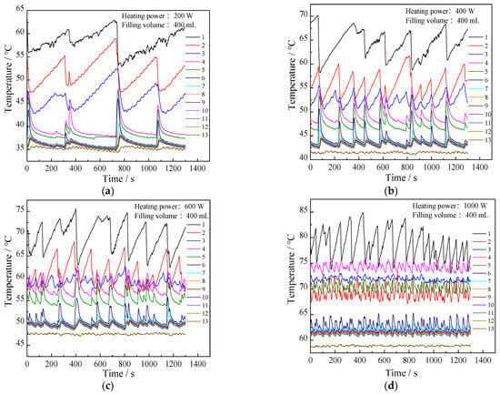
Figure 9.
Temperature variations of the heat pipe for the different heating powers (a) 200 W; (b) 400 W; (c) 600 W; (d) 1000 W. (filling volume: 400 mL, cooling-water flow rate: 6.0 mL/s; 1–13 are measuring points indicated in Figure 1).
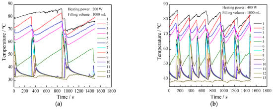
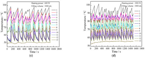
Figure 10.
Temperature variations of the heat pipe for different heating powers (a) 200 W; (b) 400 W; (c) 600 W; (d) 1000 W. (filling volume: 1000 mL, cooling-water flow rate: 6.0 mL/s; 1–13 are measuring points indicated in Figure 1).
For the same heating power, the oscillation frequency of the case with filling volume of 1000 mL is smaller than the 400 mL water filling case but the former has higher evaporation temperature. In addition, the temperature oscillating amplitude in the adiabatic section with 1000 mL filling water is bigger than that for 400 mL.
In other words, for the extra-long heat pipe, the oscillation frequency is different for the cases with different filling volumes and heating powers, and loud sounds are produced by collisions between the vibrating long heat pipe and the fixed metal frame. More heat goes into the heat pipe when the heating power is higher. Hence, the oscillation frequency of the long heat pipe increases. When the heat pipe is filled with a larger volume of water, the heat pipe has to transport more fluid and spends more time in an oscillation cycle. As a result, its oscillation frequency is lower.
In addition, it is noteworthy from Figure 9 and Figure 10 that within an oscillation period, some temperatures go up while some temperatures go down. For example, from Figure 9a, when temperatures 1–3 increase, the other temperatures (4–12) decrease; from Figure 10a, when temperatures 1–5 increase, the other temperatures (6–12) decrease. For the 400 mL water filling case, the temperature points 1–3 correspond the evaporation section part with water occupied, and for the 1000 mL water filling case, the evaporation section part with water occupied includes the temperature points 1–5. Therefore, variations of the temperatures 1–3 for the 400 mL water filling case and the temperatures 1–5 for the 1000 mL water filling case, are dominated by the intermittent boiling. However, variations of the temperature points 4–12 for the 400 mL water filling case and the temperatures 6–12 for the 1000 mL water filling case are decided by the local liquid-wetting status, which may be affected mainly by the liquid returned from the condensation section and the flushing of the liquid stored in the heat pipe evaporation section. All these factors lead to the above-described non-synchronized temperature oscillations.
4. Guideline for the Design of a Super-Long Heat Pipe for Geothermal Energy Exploitation
The experimental results and analysis above indicate that a super-long heat pipe with extreme high aspect ratio or length-diameter ratio can work well. In this experiment, the heat pipe is 30 m long with a 17 mm inner diameter. If it was scaled down to a 1 m long heat pipe, the diameter would only be 0.57 mm. Due to the large viscous resistance this needle-like heat pipe cannot work well. For a super long heat pipe with a realistic and suitable diameter it does work for any length (although this is very counterintuitive). This means, for the exploitation of the geothermal energy in hot dry rock, for any depth of the well, the heat pipe system should function. Of course, it would still be preferable for a super-long heat pipe to have a large inner diameter to reduce flow resistance and increase the heat-transfer rate.
For the optimal working-fluid filling volume, it should be ensured that the filling volume should not cause the depth of the liquid in the super-long heat pipe to be too large because high static hydraulic pressure decreases evaporation. For extraction of geothermal energy from hot dry rock, the heating section may be a few kilometers long (deep). Enough caution must be paid to the design of heat pipe inner structure to avoid too large amount of liquid accumulated in the evaporation section of heat pipe.
For a high temperature geothermal site, one should ensure that the condenser is large enough to contain all working-fluid in the heat pipe to prevent the condenser from being flooded with liquid. This can stop the heat-transfer to the condenser and fail to extract heat from the subsurface and transport it to the surface.
It is hard to avoid heat-pipe leakage completely because of the large pressure difference between heat pipe inside and outside, especially in a large and complicated geothermal system with many connection joints. Even a small amount of air leaking into the heat pipe can degrade the heat-transfer performance significantly. However, it is possible that non-condensable gas may accumulate at the top of the heat pipe because vapor flows continuously upward inside the heat pipe. Then, a vacuum port of the heat pipe can be arranged to the top. That way, once the heat-transfer rate decreases, the vacuum pump can be used to remove the non-condensable gas easily.
In addition, there may be some vibration in the super-long heat pipe, especially at high temperature and in large geothermal systems. Hence, the system must be designed sturdy enough to avoid potential damage due to vibration.
5. Conclusions
An extra-long heat pipe (30 m in length and 17 mm in inner diameter) was installed vertically to test its heat-transfer performance and operating characteristics for different filling volumes, cooling-water flow rates, and heating powers. The most important outcomes can be summarized as follows.
For a certain heating power, the optimal filling volume for the highest heat-transfer rate and lowest thermal resistance was determined to be about 40% of the volume of heated section. This is because the heat-transfer rate is determined by the evaporation temperature and how much the liquid covers the inner wall of the heated section. The evaporation temperature depends on the pressure state. When the filling volume is small, the evaporation temperature is low. However, the liquid cannot cover the inner wall of heated section completely, which results in a poor heat-transfer rate. When the filling volume is too large, even when the inner wall of the heated section is completely covered with liquid, the evaporation temperature is too high. This also leads to a low heat-transfer rate. In other words, an ideal filling volume that balances the advantages and disadvantages optimally, exists.
When the super-long heat pipe is filled with an extra-large volume of water, it cannot work properly with any amount of heating power. This is because, at a certain heating power, the evaporation temperature is high and a stable gas column forms at the lower part of the heat pipe. The gas column moves the liquid into the upper part of the heat pipe and the condenser section becomes flooded with liquid. As a result, hot vapor cannot enter the condenser section to complete the heat-transfer.
For an increasing cooling-water flow rate, the heat-transfer rate of the heat pipe increases and stabilizes slowly, while both the mean temperature of the adiabatic section and the evaporation section decrease and stabilize slowly.
In contrast to a conventional (i.e., short with a decent length-to-diameter ratio) heat pipe, a strong vibration does occur in the super-long heat pipe, and loud sounds may be produced. The oscillation frequency increases with increasing heating power and decreases with increased filling-volume.
In conclusion, the experiment shows that heat pipe can be used to extract earth-deep geothermal energy from, e.g., hot dry rock. However, enough caution must be paid when designing and manufacturing the super-long heat pipe; special inner-tube structure and suitable amount of liquid-filling ratio etc. are critically needed.
Author Contributions
Conceptualization, J.C. (Jiwen Cen) and F.J.; methodology, J.C. (Jiwen Cen), F.L., T.L., W.H. and J.C. (Juanwen Chen); software, T.L. and W.H.; validation, J.C. (Jiwen Cen) and J.C. (Juanwen Chen); formal analysis, J.C. (Juanwen Chen), F.L. and T.L.; investigation, J.C. (Jiwen Cen) and J.C. (Juanwen Chen); resources, F.J.; data curation, J.C. (Jiwen Cen) and T.L.; writing—original draft preparation, J.C. (Jiwen Cen) and T.L.; writing—review and editing, F.J.; supervision, F.J.; project administration, F.J.; funding acquisition, F.J. All authors have read and agreed to the published version of the manuscript.
Funding
This research was funded by the China National Key R&D Projects [name of funder] with grant numbers [2018YFB1501804 and 2019YFB1504104] and by the Chinese Academy of Sciences Strategic-A Pilot Project with grant number [XDA21060700].
Institutional Review Board Statement
Not applicable.
Informed Consent Statement
Not applicable.
Data Availability Statement
Not applicable.
Acknowledgments
Not applicable.
Conflicts of Interest
The authors declare no conflict of interest.
References
- Reay, D.; Kew, P.; McGlen, R. Heat Pipes—Theory, Design and Applications, 6th ed.; Elsevier Ltd.: Oxford, UK, 2014. [Google Scholar]
- Faghri, A.; Zhang, Y.W. Transport Phenomena in Multiphase Systems; Elsevier Ltd.: Oxford, UK, 2006. [Google Scholar]
- Meseguer, J.; Pérez-Grande, I.; Sanz-Andrés, A. Spacecraft Thermal Control; Woodhead Publishing Limited: Cambridge, UK, 2012. [Google Scholar]
- Huang, D.S.; Chen, T.C.; Tsai, L.T.; Lin, M.T. Design of fins with a grooved heat pipe for dissipation of heat from high-powered automotive LED headlights. Energy Convers. Manag. 2019, 180, 550–558. [Google Scholar] [CrossRef]
- Lu, J.Z.; Shen, L.M.; Huang, Q.J.; Sun, D.F.; Li, B.; Tan, Y.J. Investigation of a rectangular heat pipe radiator with parallel heat flow structure for cooling high-power IGBT modules. Int. J. Therm. Sci. 2019, 135, 83–93. [Google Scholar] [CrossRef]
- Zhou, W.J.; Li, Y.; Chen, Z.S.; Deng, L.Q.; Gan, Y.H. A novel ultra-thin flattened heat pipe with biporous spiral woven mesh wick for cooling electronic devices. Energy Convers. Manag. 2019, 180, 769–783. [Google Scholar] [CrossRef]
- Zhou, G.H.; Li, J.; Jia, Z.Z. Power-saving exploration for high-end ultra-slim laptop computers with miniature loop heat pipe cooling module. Appl. Energy 2019, 239, 859–875. [Google Scholar] [CrossRef]
- Patel, V.K. An efficient optimization and comparative analysis of ammonia and methanol heat pipe for satellite application. Energy Convers. Manag. 2018, 165, 382–395. [Google Scholar] [CrossRef]
- Maraj, A.; Londo, A.; Gebremedhin, A.; Firat, C. Energy performance analysis of a forced circulation solar water heating system equipped with a heat pipe evacuated tube collector under the Mediterranean climate conditions. Renew. Energy 2019, 140, 874–883. [Google Scholar] [CrossRef]
- Allouhi, A.; Amine, M.B.; Buker, M.S.; Kousksou, T.; Jamil, A. Forced-circulation solar water heating system using heat pipe-flat plate collectors: Energy and exergy analysis. Energy 2019, 180, 429–443. [Google Scholar] [CrossRef]
- Liao, Z.R.; Xu, C.; Ren, Y.X.; Gao, F.; Ju, X.; Du, X.Z. Thermal analysis of a conceptual loop heat pipe for solar central receivers. Energy 2018, 158, 709–718. [Google Scholar] [CrossRef]
- Yang, Y.P.; Wei, Q.C.; Zhou, S.H. Thermosyphon Technology and Its Application in Permafrost. Chin. J. Geotech. Eng. 2005, 27, 698–706. (In Chinese) [Google Scholar]
- Wang, X.Y.; Fan, H.T.; Zhu, Y.Z.; Zhu, M.Z. Heat transfer simulation and analysis of ice and snow melting system using geothermy by super-long flexible heat pipes. Energy Procedia 2017, 105, 4724–4730. [Google Scholar] [CrossRef]
- Anderson, A.; Rezaie, B. Geothermal technology: Trends and potential role in a sustainable future. Appl. Energy 2019, 248, 25–31. [Google Scholar] [CrossRef]
- Wang, G.L.; Zhang, W.; Ma, F.; Lin, W.J.; Liang, J.Y.; Zhu, X. Overview on hydrothermal and hot dry rock researches in China. China Geol. 2018, 2, 273–285. [Google Scholar] [CrossRef]
- Chaudhry, H.N.; Hughes, B.R.; Ghani, S.A. A review of heat pipe systems for heat recovery and renewable energy applications. Renew. Sustain. Energy Rev. 2012, 16, 2249–2259. [Google Scholar] [CrossRef]
- Faghri, A. Heat pipes: Review, opportunities and challenges. Front. Heat Pipes 2014, 5, 1–48. [Google Scholar] [CrossRef]
- Franco, A.; Vaccaro, M. On the use of heat pipe principle for the exploration of medium-low temperature geothermal resources. Appl. Therm. Eng. 2013, 59, 189–199. [Google Scholar] [CrossRef]
- Seo, J.; Bang, I.C.; Lee, J.Y. Length effect on entrainment limit of large-L/D vertical heat pipe. Int. J. Heat Mass Transf. 2016, 97, 751–759. [Google Scholar] [CrossRef]
- Che, H.C.; Yan, D.H.; Ren, Y.Y.; Liu, Y.J. Research on wellbore gravity heat pipe heating technology in thermal recovery of heavy oil. Pet. Drill. Tech. 2011, 39, 108–111. (In Chinese) [Google Scholar]
- Kusaba, S.; Suzuki, H.; Hirowatari, K.; Mochizuki, M.; Akbarzadeh, A. Extraction of geothermal energy and electric power generation using a large scale heat pipe. In Proceedings of the World Geothermal Congress, Kyushu-Tohoku, Japan, 28 May–10 June 2000; pp. 3489–3494. [Google Scholar]
- Jiang, F.M.; Huang, W.B.; Cao, W.J. Mining Hot Dry Rock Geothermal Energy by Heat Pipe: Conceptual Design and Technical Feasibility Study. Adv. New Renew. Energy 2017, 5, 426–434. (In Chinese) [Google Scholar]
- Huang, W.; Cen, J.; Chen, J.; Cao, W.; Li, Z.; Li, F.; Jiang, F. Heat Extraction from Earth-deep Hot Dry Rock by Super-long Gravity Heat Pipe: A Field Test. 2021. in preparation. [Google Scholar]
- Dai, H. Heat extraction from the deep geothermal well by 3000-meter long heat pipe: The personality interview of Dr. F. Jiang. Ground Source Heat Pump 2020. (In Chinese) [Google Scholar]
- Chi, H. A Novel Single Well HDR Energy Extraction Technology. Chinese Science News 2020-07-22. Available online: http://news.sciencenet.cn/dz/dznews_photo.aspx?t=&id=34771 (accessed on 22 July 2020). (In Chinese).
Publisher’s Note: MDPI stays neutral with regard to jurisdictional claims in published maps and institutional affiliations. |
© 2021 by the authors. Licensee MDPI, Basel, Switzerland. This article is an open access article distributed under the terms and conditions of the Creative Commons Attribution (CC BY) license (https://creativecommons.org/licenses/by/4.0/).