
Experimental Study of the Fatigue Performance of the Bonding Surfaces and Load-Bearing Capacity of a Large-Scale Severely Damaged Hollow Slab Strengthened by CFRP


Abstract
:1. Introduction
2. Experimental Preparation
2.1. Test Specimen
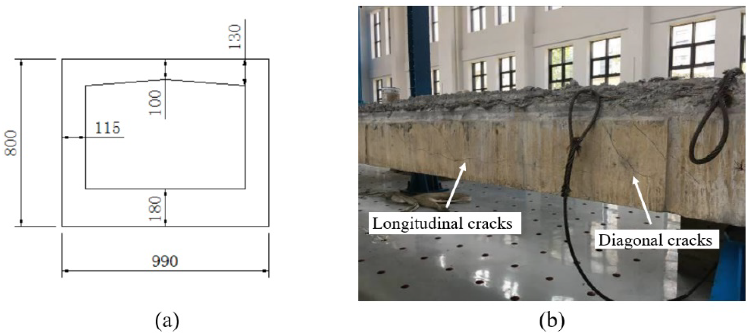
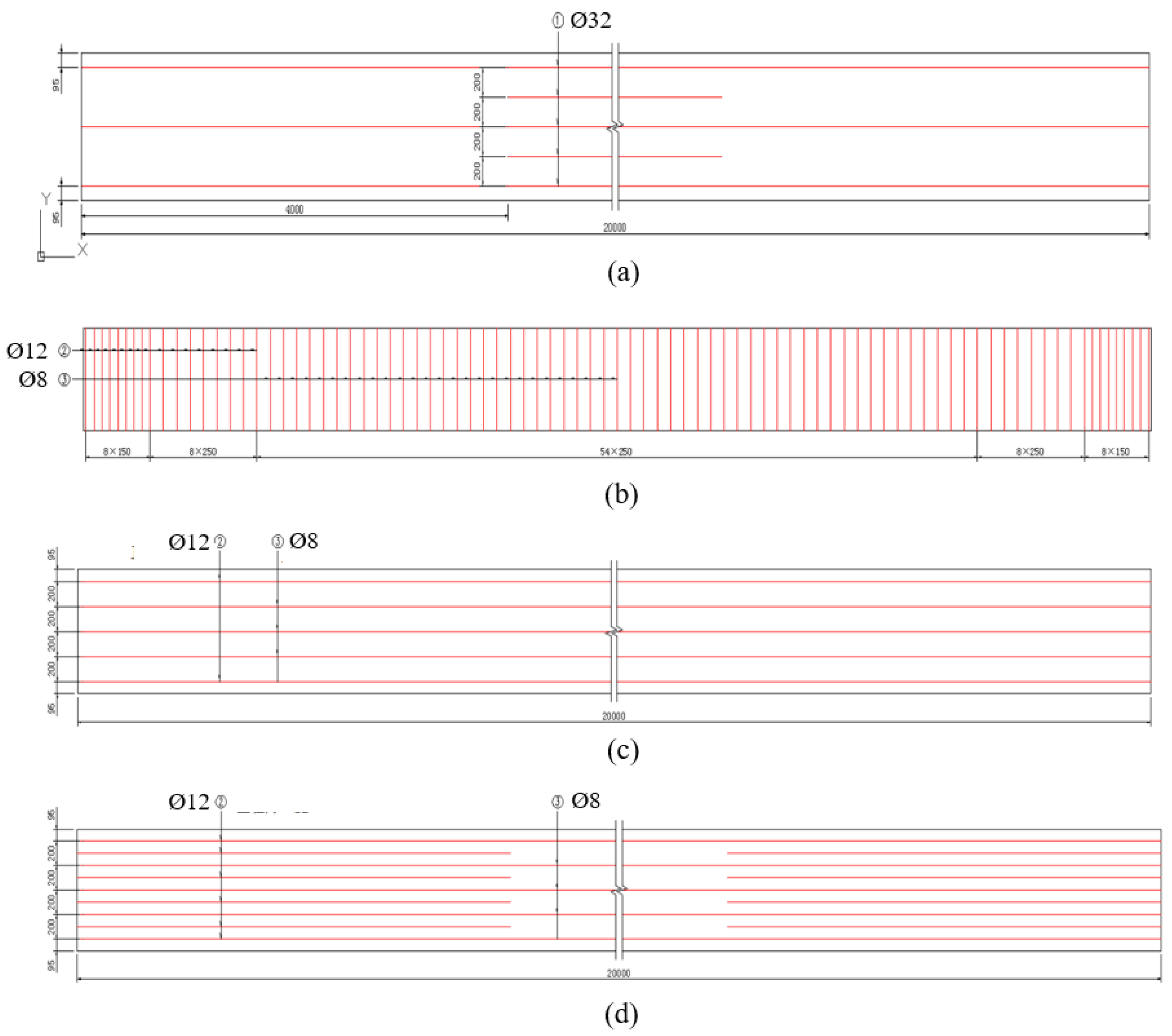
2.1.1. A Decommissioned Prestressed Concrete Hollow Slab
2.1.2. Destructive Test
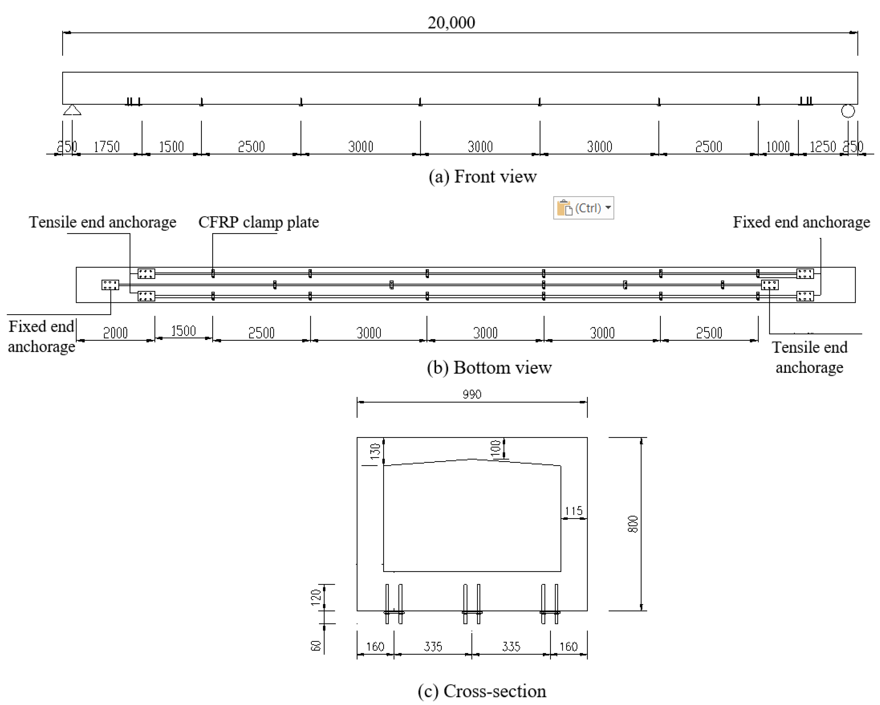
2.2. CFRP Strengthening for Severely Damaged Slab
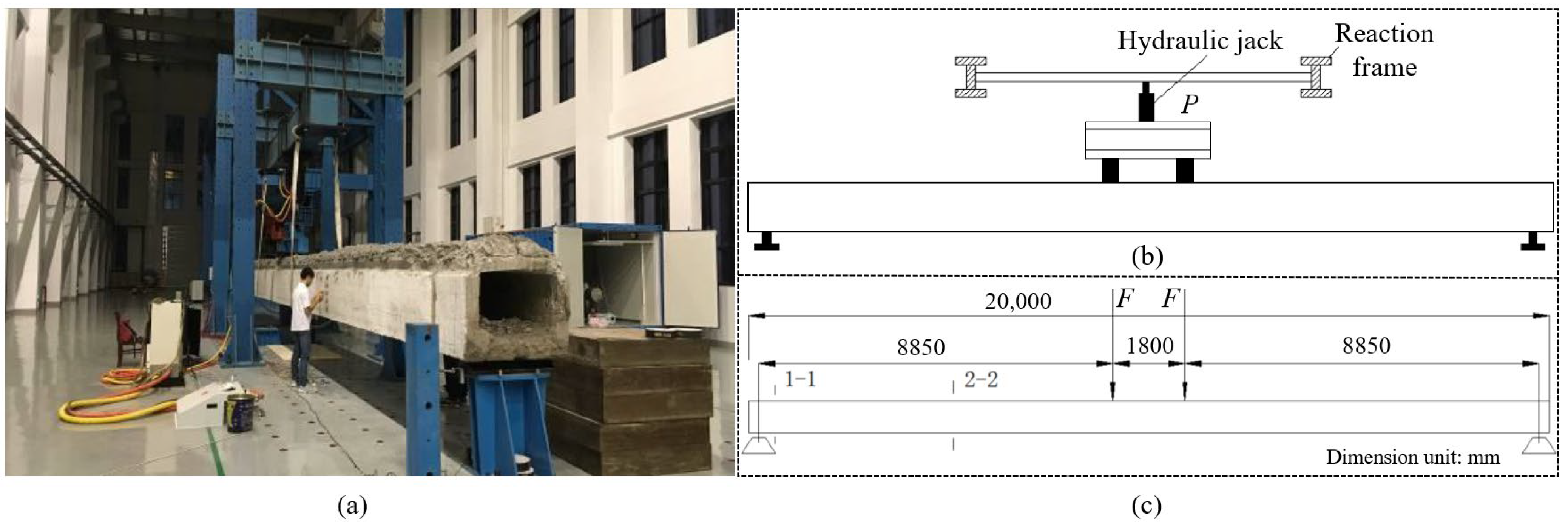
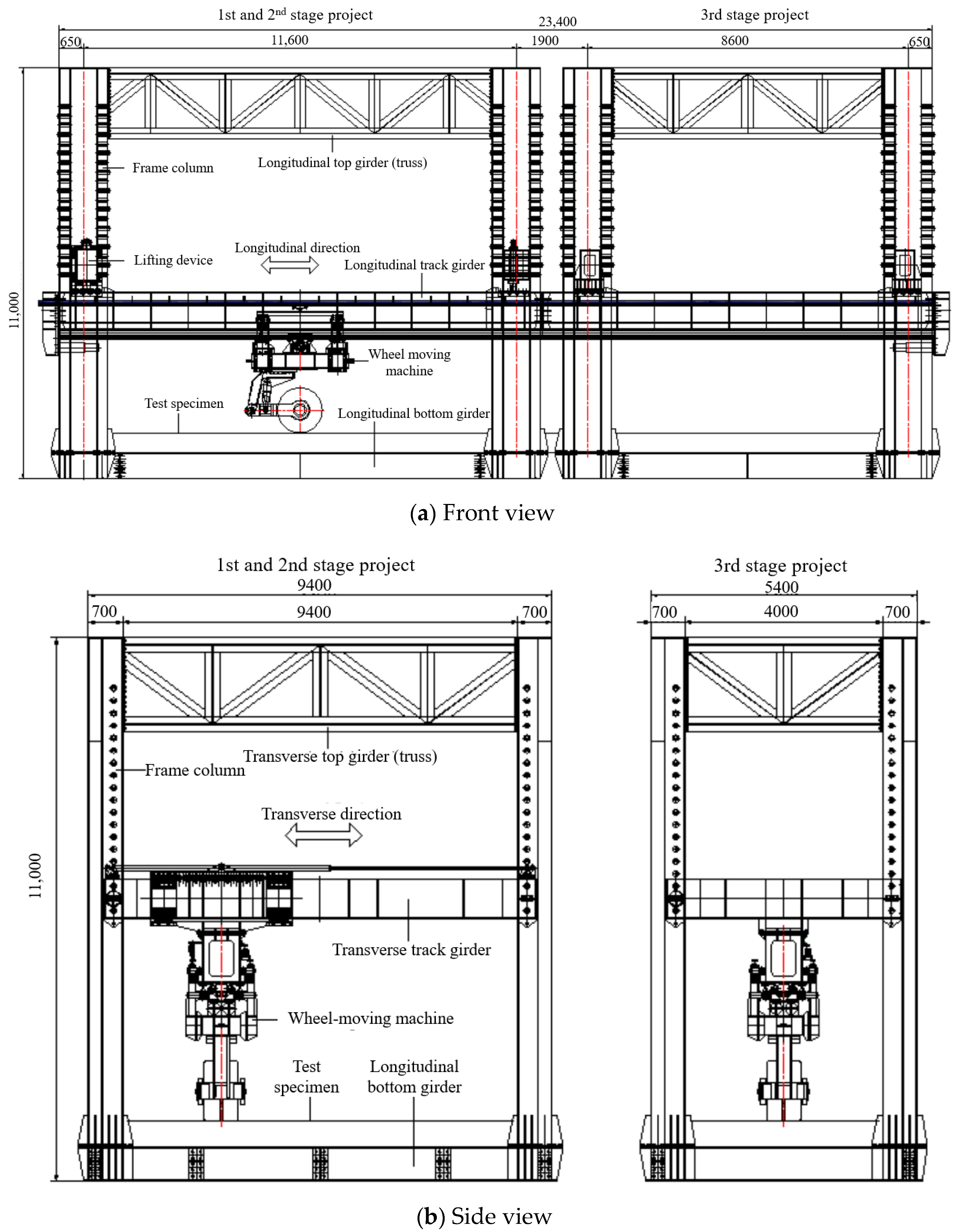
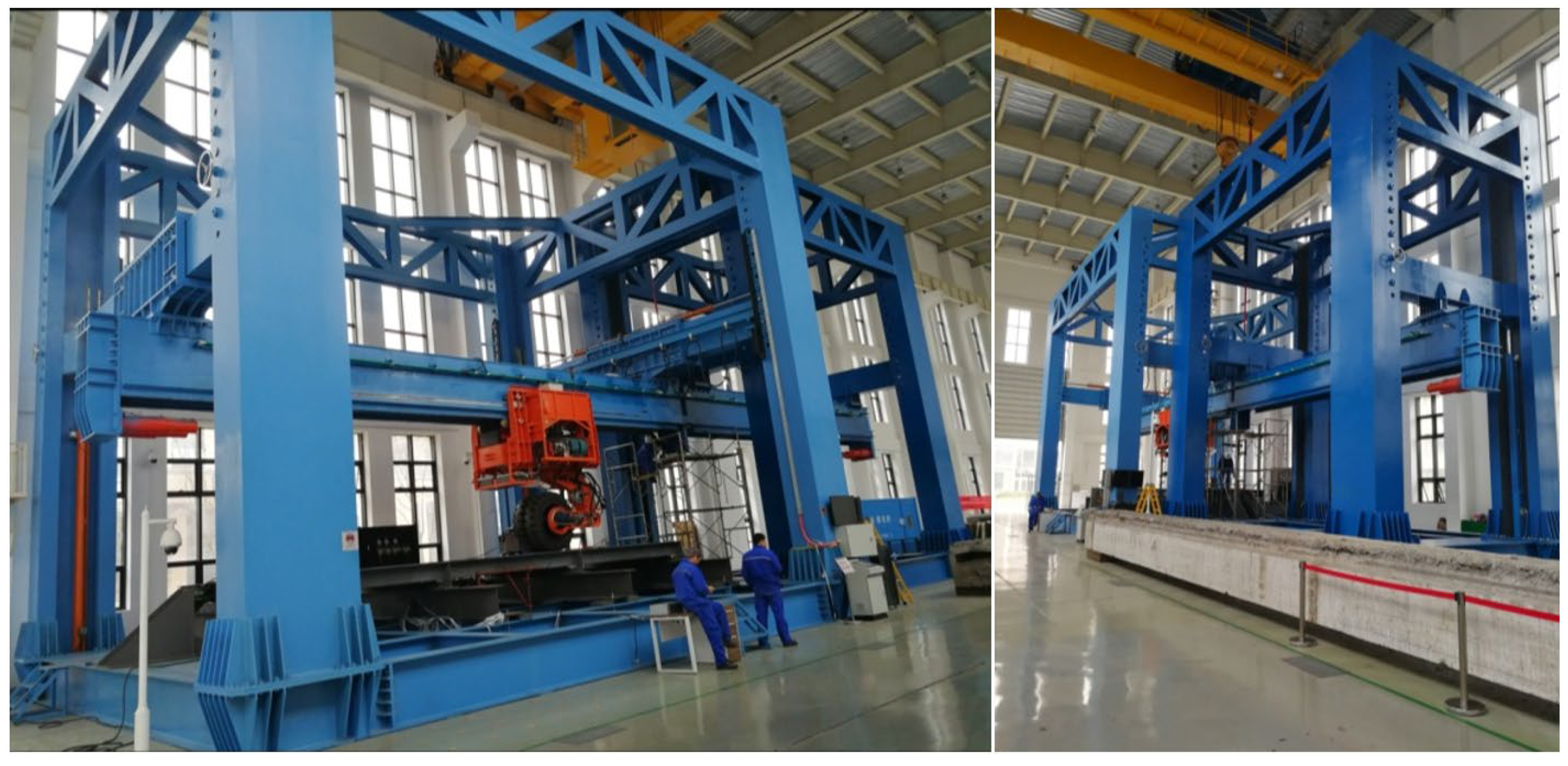
2.3. Test Machine
3. Fatigue Load Test for the CFRP-Strengthened Slab and Result Analysis
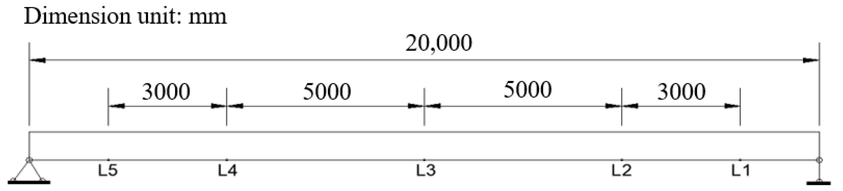
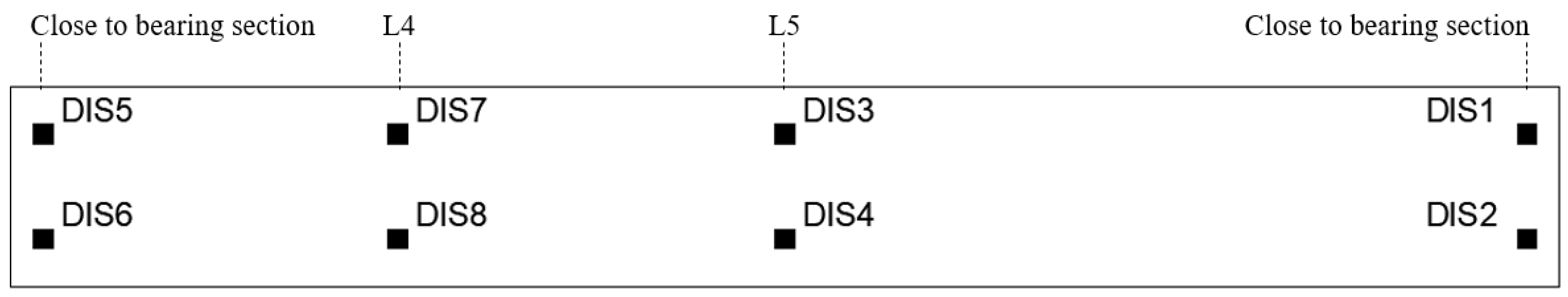
3.1. Fatigue Load Cases and Experimental Set-Up
3.2. Result Analysis
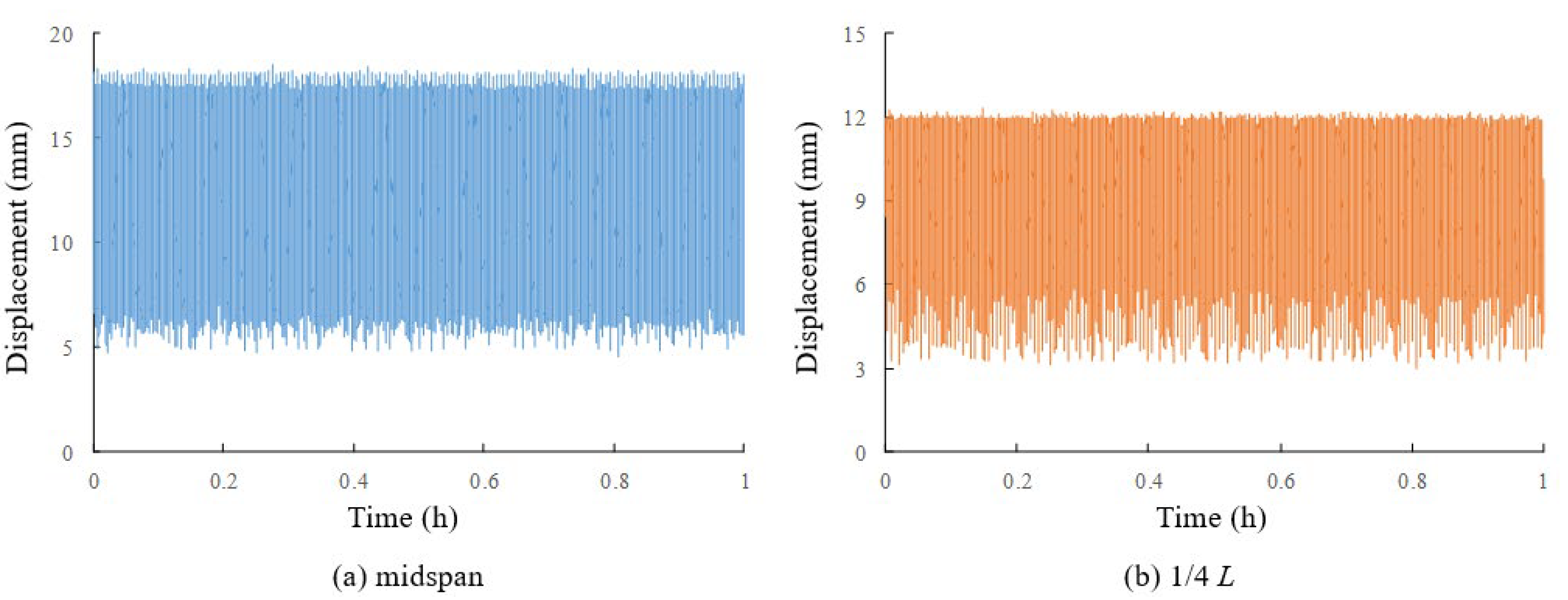
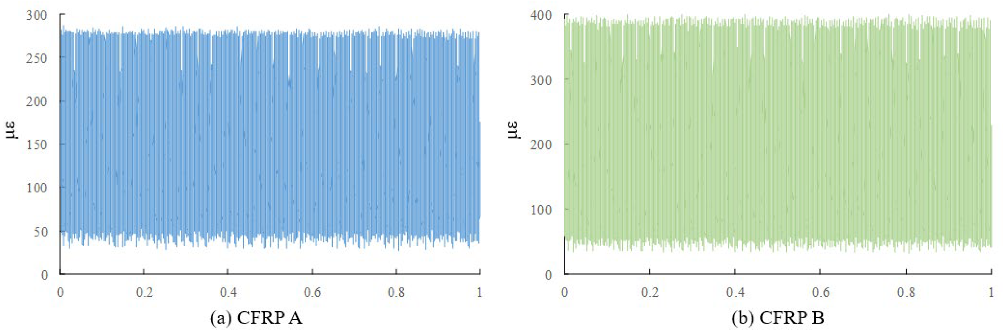
3.2.1. Moving Load Case
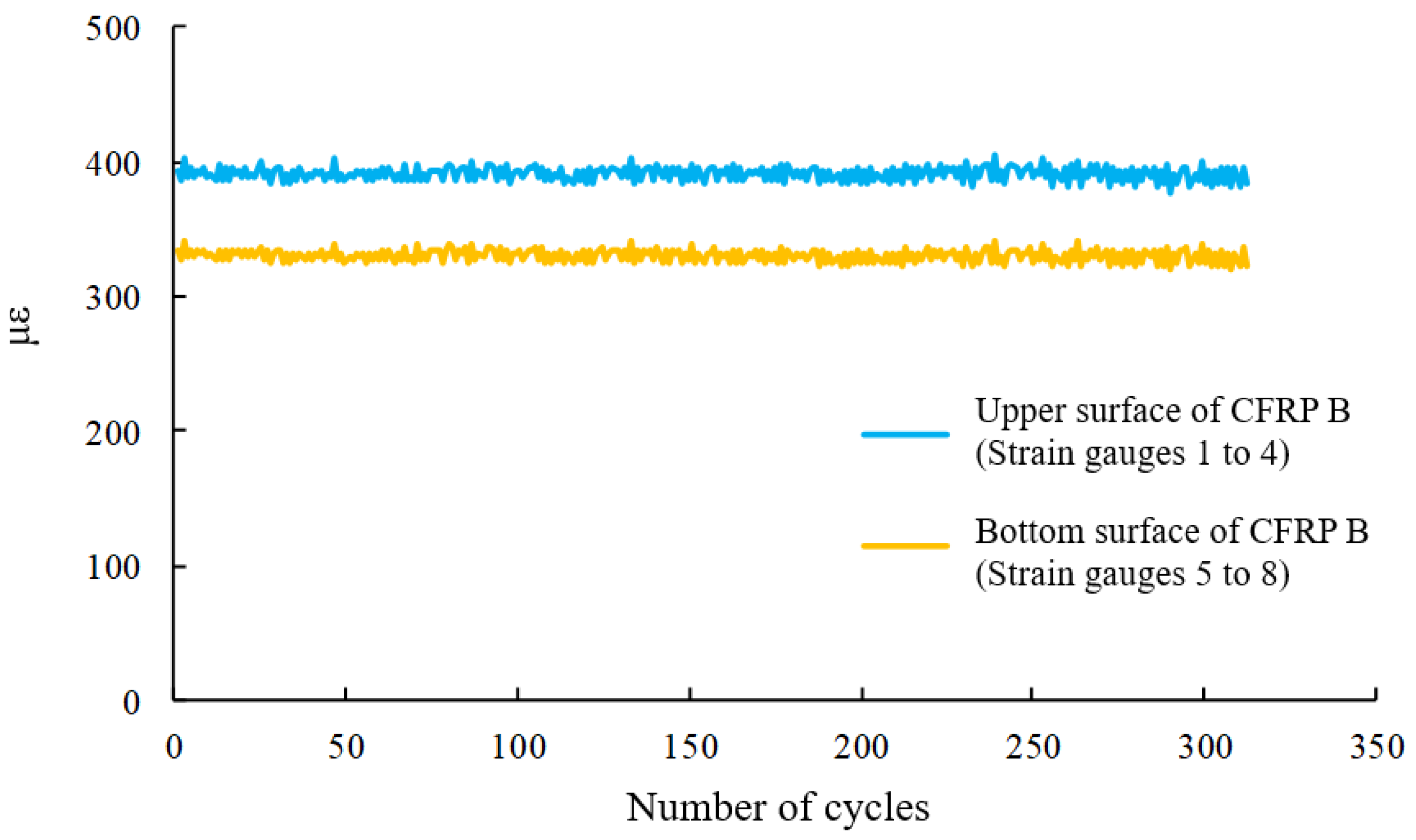
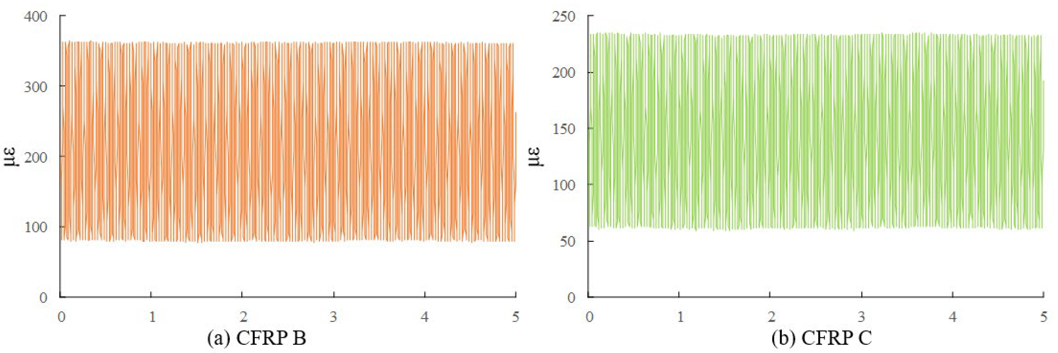
3.2.2. Single Point Sinusoidal Load Case
3.2.3. Comparisons
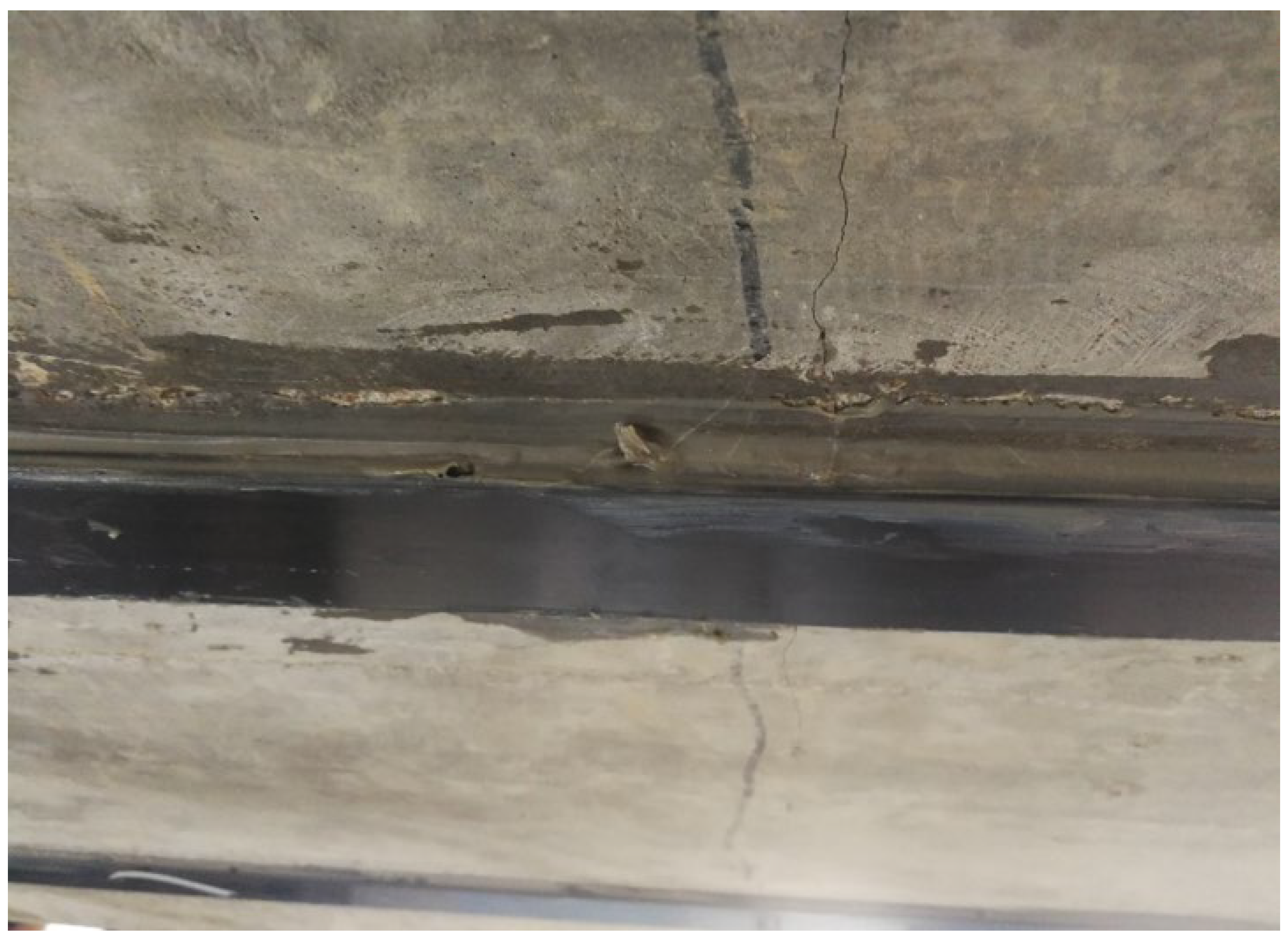
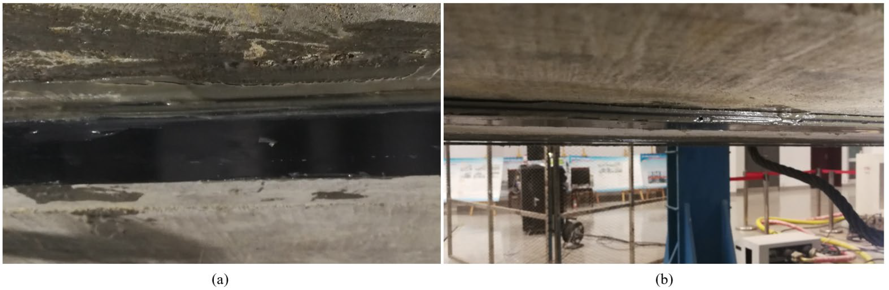
3.2.4. Fatigue Performance Observations in CFRP-Concrete Bonding Surface
4. Load-Bearing Capacity Test for the CFRP-Strengthened Slab and Result Analysis
4.1. Load Program and Experimental Set-Up
4.2. Results Analysis
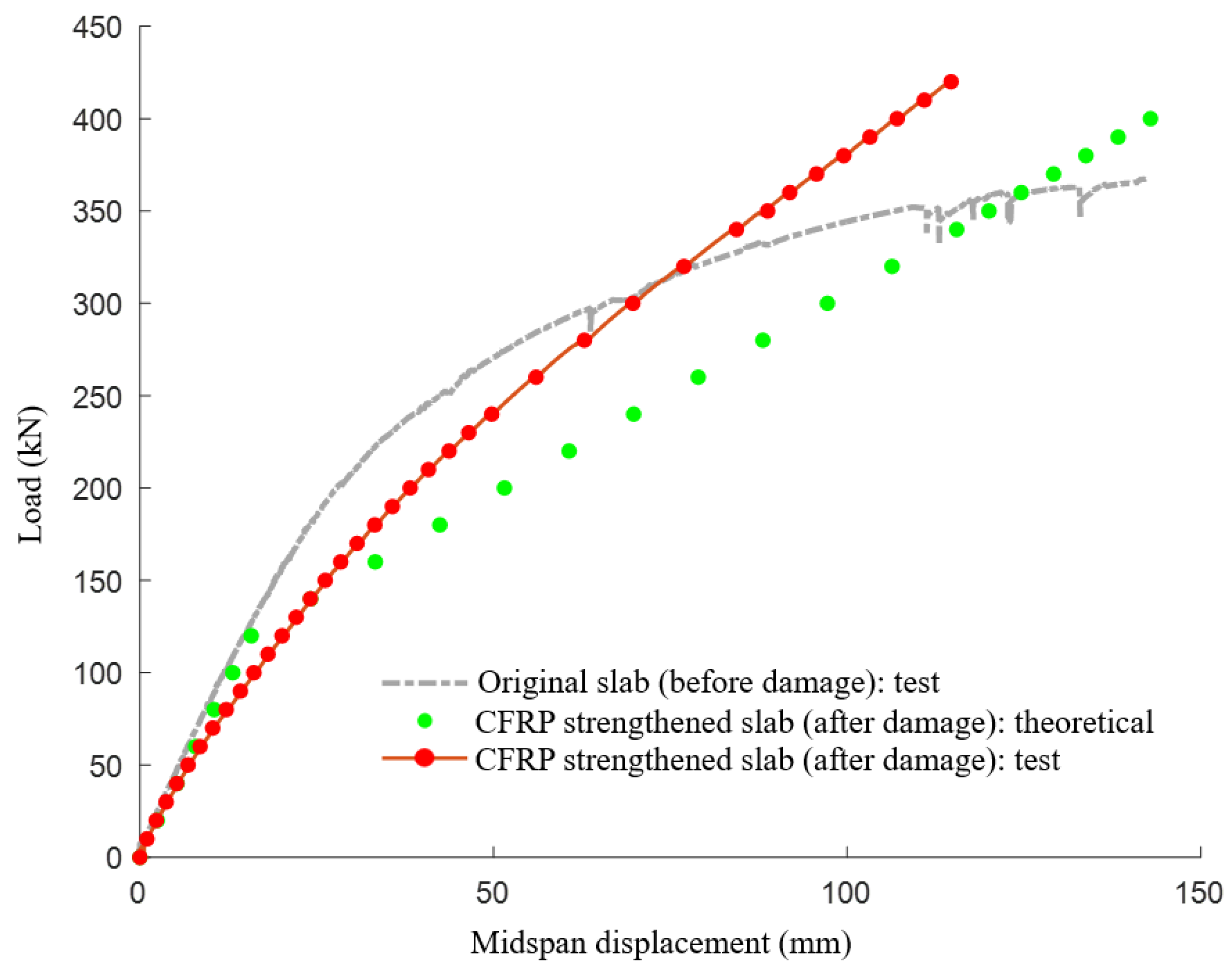
4.2.1. Overall
4.2.2. Analysis of Strain Data
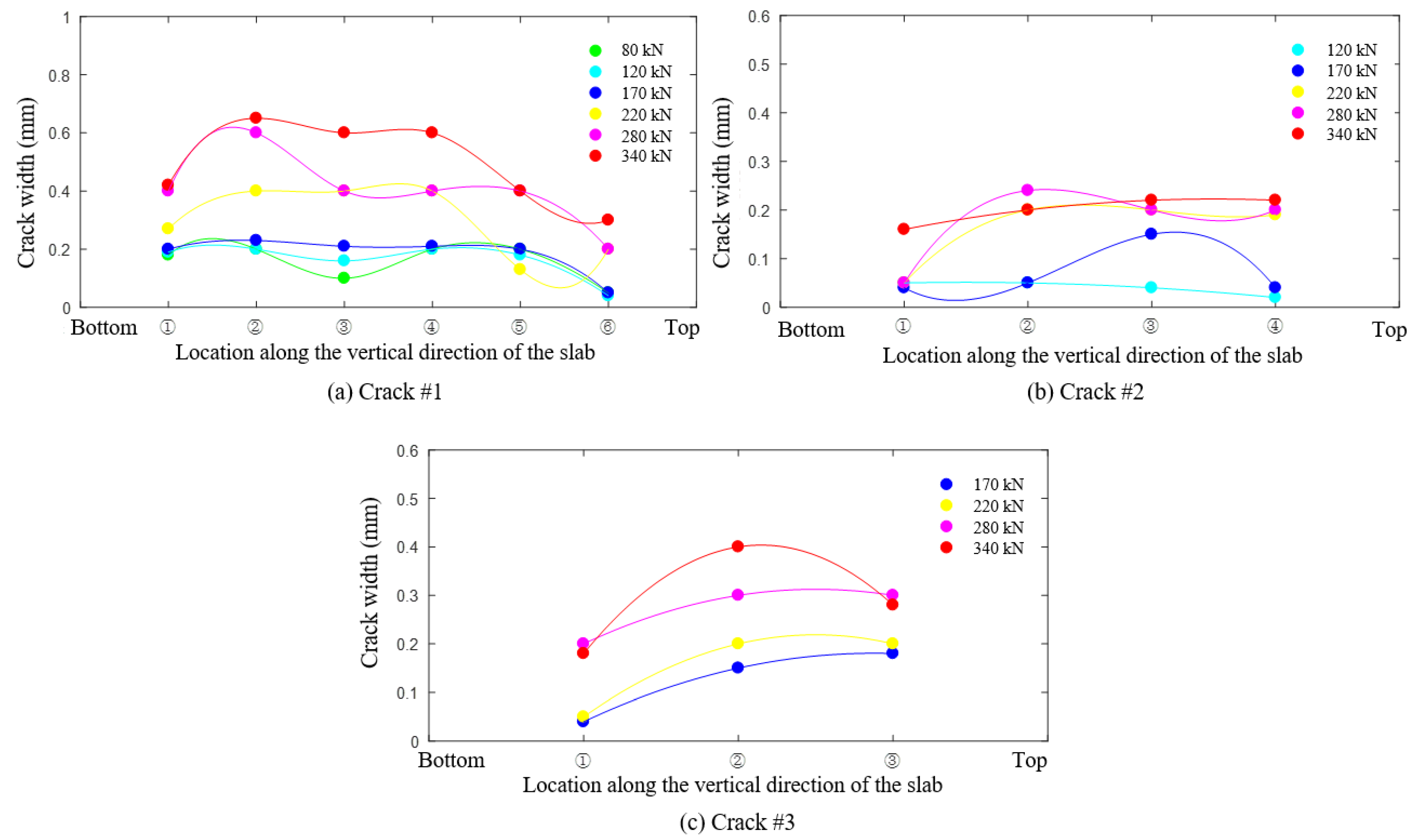
4.2.3. Analysis of Cracks
5. Conclusions
- The adhesive failure and debonding effects were investigated using the fatigue load test on the CFRP-strengthened hollow slab. The CFRP-concrete surface began to show some white lines when the load cycles reached 5000 iterations. Additionally, with increasing cycles, the number of white lines also increased. There was no fatigue damage in the concrete and rebars of the hollow slab.
- With the CFRP strengthening, the severely damaged hollow slab was still able to perform well under normal operational load (Highway Grade I). Additionally, the fatigue performance of the CFRP-concrete bonding surface was able to satisfy real-world operational service requirements in the short term.
- Structural responses caused by moving loads were generally larger than those caused by single point sinusoidal loads. These results demonstrate that moving loads had a greater impact on the tested hollow slab. Therefore, when replacing moving loads with single point loads for fatigue testing, it is recommended to increase the upper limit of the fatigue loads.
- The load-bearing capacity of the CFRP-strengthened slab (after damage) was improved by at least 13.5% compared to the original healthy slab (before damage).
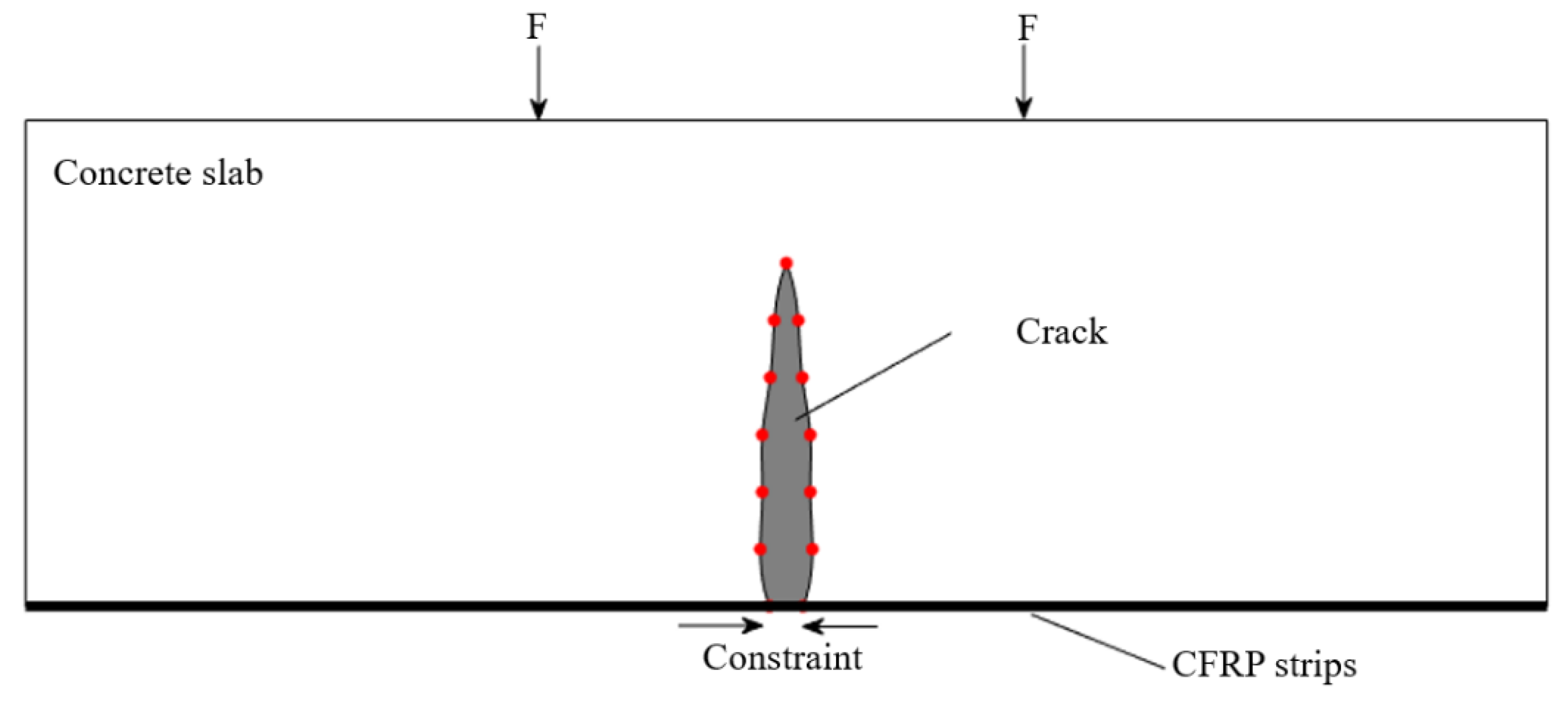
- During the load-bearing capacity test, no new cracks appeared in the CFRP-strengthened hollow slab. The crack width at the middle section of the slab height was larger than at the bottom and top sections. In the CFRP-strengthened slab, the bottom of the slab was constrained by the CFRP strips, and crack development was inhibited.
Author Contributions
Funding
Institutional Review Board Statement
Informed Consent Statement
Data Availability Statement
Acknowledgments
Conflicts of Interest
References
- Dong, C.Z.; Bas, S.; Catbas, F.N. A portable monitoring approach using cameras and computer vision for bridge load rating in smart cities. J. Civ. Struct. Health Monit. 2020, 10, 1001–1021. [Google Scholar] [CrossRef]
- American Society of Civil Engineers. 2021 Report Card for America’s Infrastructure; American Society of Civil Engineers: Reston, VA, USA, 2021. [Google Scholar]
- Di, J.; Sun, Y.; Yu, K.; Liu, L.; Qin, F. Experimental investigation of shear performance of existing PC hollow slab. Eng. Struct. 2020, 211, 110451. [Google Scholar] [CrossRef]
- Dong, C.Z.; Bas, S.; Debees, M.; Alver, N.; Catbas, F.N. Bridge load testing for identifying live load distribution, load rating, serviceability and dynamic response. Front. Built Environ. 2020, 6, 46. [Google Scholar] [CrossRef]
- Dong, C.Z.; Catbas, F.N. A review of computer vision–based structural health monitoring at local and global levels. Struct. Health. Monit. 2020, 20, 692–743. [Google Scholar] [CrossRef]
- Jin, H.; Jiang, H.; Jiang, R.; Zhan, H.; Xu, Y. Strengthening hollow core concrete bridges with deficient transverse hinge joints with a steel and concrete composite anchorage system. Transp. Res. Rec. 2020, 2674, 68–78. [Google Scholar] [CrossRef]
- Wang, S.C.; Wang, C.S.; Wang, Q.; Tian, X.F. Full-scale experimental validation of the steel plate- prestressed concrete composite method for the strengthening of hollow slab girders. Life-Cycle Civ. Eng. Innov. Theory Pract. 2021, 924–930. [Google Scholar]
- Zulkifli, S.N.I.; Hisbany, M.H.M.; Ismail, R.; Zakwan, F.A.A.; Hazrina, A.; Ismail, B.N.; Rashid, R.S.M. Application of shape memory alloys (SMA) as a retrofit and strengthening component on reinforced concrete columns: Review Paper. J. Phys. Conf. Ser. 2020, 1529, 042104. [Google Scholar] [CrossRef]
- Zhao, H.; Andrawes, B. Local strengthening and repair of concrete bridge girders using shape memory alloy precast prestressing plate. J. Intell. Mater. Syst. Struct. 2020, 31, 1343–1357. [Google Scholar] [CrossRef]
- Harajli, M.; Khairallah, N.; Nassif, H. Externally prestressed members: Evaluation of second-order effects. J. Struct. Eng. 1999, 125, 1151–1161. [Google Scholar] [CrossRef]
- Tan, K.H.; Tjandra, R.A. Strengthening of RC continuous beams by external prestressing. J. Struct. Eng. 2007, 133, 195–204. [Google Scholar] [CrossRef]
- Teng, J.G.; Chen, J.F.; Smith, S.T.; Lam, L. Behaviour and strength of FRP-strengthened RC structures: A state-of-the-art review. Proc. Inst. Civ. Eng. Struct. Build. 2003, 156, 51–62. [Google Scholar] [CrossRef]
- Al-Salih, H.; Bennett, C.; Matamoros, A. Evaluation of novel combined CFRP-steel retrofit for repairing distortion-induced fatigue. J. Constr. Steel Res. 2021, 182, 106642. [Google Scholar] [CrossRef]
- Heydarinouri, H.; Nussbaumer, A.; Motavalli, M.; Ghafoori, E. Strengthening of steel connections in a 92-year-old railway bridge using prestressed CFRP rods: Multiaxial fatigue design criterion. J. Bridg. Eng. 2021, 26, 04021023. [Google Scholar] [CrossRef]
- Beneberu, E.; Yazdani, N. Performance of CFRP-strengthened concrete bridge girders under combined live load and hydrocarbon fire. J. Bridge Eng. 2018, 23, 04018042. [Google Scholar] [CrossRef]
- Radhi, M.S.; Hassan, M.S.; Gorgis, I.N. Carbon fibre-reinforced polymer confinement of corroded circular concrete columns. J. Build. Eng. 2021, 43, 102611. [Google Scholar] [CrossRef]
- Pelà, L.; Aprile, A.; Benedetti, A. Experimental study of retrofit solutions for damaged concrete bridge slabs. Compos. Part B Eng. 2012, 43, 2471–2479. [Google Scholar] [CrossRef]
- Ghous Sohail, M.; Al Nuaimi, N.; Hawileh, R.A.; Abdalla, J.A.; Douier, K. Durability of plain concrete prism strengthened with galvanized steel mesh and CFRP laminates under harsh environmental conditions. Constr. Build. Mater. 2021, 286, 15–19. [Google Scholar] [CrossRef]
- Siddika, A.; Al Mamun, M.A.; Ferdous, W.; Alyousef, R. Performances, challenges and opportunities in strengthening reinforced concrete structures by using FRPs—A state-of-the-art review. Eng. Fail. Anal. 2020, 111, 104480. [Google Scholar] [CrossRef]
- Lee, L.S.; Jain, R. The role of FRP composites in a sustainable world. Clean Technol. Environ. Policy 2009, 11, 247–249. [Google Scholar] [CrossRef]
- Siwowski, T.; Piątek, B.; Siwowska, P.; Wiater, A. Development and implementation of CFRP post-tensioning system for bridge strengthening. Eng. Struct. 2020, 207, 110266. [Google Scholar] [CrossRef]
- Farrokh Ghatte, H. External steel ties and CFRP jacketing effects on seismic performance and failure mechanisms of substandard rectangular RC columns. Compos. Struct. 2020, 248, 112542. [Google Scholar] [CrossRef]
- Farrokh Ghatte, H.; Comert, M.; Demir, C.; Akbaba, M.; Ilki, A. Seismic retrofit of full-scale substandard extended rectangular RC columns through CFRP jacketing: Test results and design recommendations. J. Compos. Constr. 2019, 23, 04018071. [Google Scholar] [CrossRef]
- Pham, T.M.; Hao, H. Review of concrete structures strengthened with FRP against impact loading. Structures 2016, 7, 59–70. [Google Scholar] [CrossRef] [Green Version]
- Buyukozturk, O.; Gunes, O.; Karaca, E. Progress on understanding debonding problems in reinforced concrete and steel members strengthened using FRP composites. Constr. Build. Mater. 2004, 18, 9–19. [Google Scholar] [CrossRef]
- Buyukozturk, O.; Hearing, B. Failure behavior of precracked concrete beams retrofitted with FRP. J. Compos. Constr. 1998, 2, 138–144. [Google Scholar] [CrossRef]
- Yao, J.; Teng, J.G.; Lam, L. Experimental study on intermediate crack debonding in FRP-strengthened RC flexural members. Adv. Struct. Eng. 2005, 8, 365–395. [Google Scholar] [CrossRef]
- Al-Ghrery, K.; Al-Mahaidi, R.; Kalfat, R.; Oukaili, N.; Al-Mosawe, A. Experimental investigation of curved-soffit RC Bridge girders strengthened in flexure using CFRP composites. J. Bridg. Eng. 2021, 26, 04021009. [Google Scholar] [CrossRef]
- Kotynia, R.; Walendziak, R.; Stoecklin, I.; Meier, U. RC slabs strengthened with prestressed and gradually anchored CFRP strips under monotonic and cyclic loading. J. Compos. Constr. 2011, 15, 168–180. [Google Scholar] [CrossRef]
- Cai, J.; Hao, H.; Ozbakkaloglu, T.; Zhang, Y.; Pan, J. Behavior of geopolymeric recycled aggregate concrete-filled FRP tube (GRACFFT) columns under lateral cyclic loading. Eng. Struct. 2020, 222, 111047. [Google Scholar] [CrossRef]
- Yao, J.; Teng, J.G. Plate end debonding in FRP-plated RC beams-I: Experiments. Eng. Struct. 2007, 29, 2457–2471. [Google Scholar] [CrossRef]
- Teng, J.G.; Yao, J. Plate end debonding in FRP-plated RC beams-II: Strength model. Eng. Struct. 2007, 29, 2472–2486. [Google Scholar] [CrossRef]
- Yoshitake, I.; Hasegawa, H.; Shimose, K. Monotonic and cyclic loading tests of reinforced concrete beam strengthened with bond-improved carbon fiber reinforced polymer (CFRP) rods of ultra-high modulus. Eng. Struct. 2020, 206, 110175. [Google Scholar] [CrossRef]
- Alam, M.S.; Sultana, N.; Hossain, S.M.Z. Bayesian optimization algorithm based support vector regression analysis for estimation of shear capacity of FRP reinforced concrete members. Appl. Soft Comput. 2021, 105, 107281. [Google Scholar] [CrossRef]
- Saadah, M.; Ashteyat, A.; Murad, Y. Shear strengthening of RC beams using side near surface mounted CFRP ropes and strips. Structures 2021, 32, 380–390. [Google Scholar] [CrossRef]
- Teng, J.G.; Chen, G.M.; Chen, J.F.; Rosenboom, O.A.; Lam, L. Behavior of RC beams shear strengthened with bonded or unbonded FRP wraps. J. Compos. Constr. 2009, 13, 394–404. [Google Scholar] [CrossRef] [Green Version]
- Peng, H.; Zhang, J.; Cai, C.S.; Liu, Y. An experimental study on reinforced concrete beams strengthened with prestressed near surface mounted CFRP strips. Eng. Struct. 2014, 79, 222–233. [Google Scholar] [CrossRef]
- Triantafillou, T.; Deskovic, N.; Deuring, M. Strengthening of concrete structures with prestressed FRP sheets. ACI Struct. J. 1992, 89, 235–244. [Google Scholar]
- Quantrill, R.J.; Hollaway, L.C. The flexural rehabilitation of reinforced concrete beams by the use of prestressed advanced composite plates. Compos. Sci. Technol. 1998, 58, 1259–1275. [Google Scholar] [CrossRef]
- Wight, R.G.; Green, M.F.; Erki, M.A. Prestressed FRP sheets for poststrengthening reinforced concrete beams. J. Compos. Constr. 2001, 5, 214–220. [Google Scholar] [CrossRef]
- Moshiri, N.; Czaderski, C.; Mostofinejad, D.; Hosseini, A.; Sanginabadi, K.; Breveglieri, M.; Motavalli, M. Flexural strengthening of RC slabs with nonprestressed and prestressed CFRP strips using EBROG method. Compos. Part B Eng. 2020, 201, 108359. [Google Scholar] [CrossRef]
- Chalot, A.; Michel, L.; Ferrier, E. Experimental study of external bonded CFRP-concrete interface under low cycle fatigue loading. Compos. Part B Eng. 2019, 177, 107255. [Google Scholar] [CrossRef]
- Zhou, H.; Fernando, D.; Thuan Nguyen, V.; Dai, J.G. The bond behaviour of CFRP-to-concrete bonded joints under fatigue cyclic loading: An experimental study. Constr. Build. Mater. 2021, 273, 121674. [Google Scholar] [CrossRef]
- CABR. Code for Acceptance of Constructional Quality of Concrete Structures, 2015th ed.; GB 50204-2015; China Architecture & Building Press: Beijing, China, 2015. [Google Scholar]


| Technical Item | Value |
|---|---|
| Tensile strength (MPa) | ≥2400 |
| Tensile modulus (GPa) | ≥160 |
| Interlaminar shear strength (MPa) | ≥50 |
| Elongation rate (%) | ≥1.6 |
| Tensile bonding strength with concrete (MPa) | ≥2.5 |
| Fiber percentage by volume (%) | ≥65 |
| Items | Load Case | Value | Difference |
|---|---|---|---|
| Midspan displacement (mm) | Moving | 17.8 | 6.4% |
| Single | 16.7 | ||
| Average peek strain value in CFRP A (×10−6) | Moving | 278.6 | 21.3% |
| Single | 224.9 | ||
| Average peek strain value in CFRP B (×10−6) | Moving | 390.8 | 8.7% |
| Single | 357.9 | ||
| Average peek strain value in CFRP C (×10−6) | Moving | 230.2 | −0.5% |
| Single | 231.4 |
| Load Case | Midspan Displacement (mm) |
|---|---|
| Moving load, after strengthen | 17.8 |
| Single load, after strengthen | 16.7 |
| Static load, after strengthen | 20.1 |
| Static load, before damage | 14.7 |
Publisher’s Note: MDPI stays neutral with regard to jurisdictional claims in published maps and institutional affiliations. |
© 2021 by the authors. Licensee MDPI, Basel, Switzerland. This article is an open access article distributed under the terms and conditions of the Creative Commons Attribution (CC BY) license (https://creativecommons.org/licenses/by/4.0/).
Share and Cite
Hu, H.; Dong, C.-Z.; Wang, J.; Chen, J. Experimental Study of the Fatigue Performance of the Bonding Surfaces and Load-Bearing Capacity of a Large-Scale Severely Damaged Hollow Slab Strengthened by CFRP. Sustainability 2021, 13, 12179. https://doi.org/10.3390/su132112179
Hu H, Dong C-Z, Wang J, Chen J. Experimental Study of the Fatigue Performance of the Bonding Surfaces and Load-Bearing Capacity of a Large-Scale Severely Damaged Hollow Slab Strengthened by CFRP. Sustainability. 2021; 13(21):12179. https://doi.org/10.3390/su132112179
Chicago/Turabian StyleHu, Hao, Chuan-Zhi Dong, Jiji Wang, and Jiaqi Chen. 2021. "Experimental Study of the Fatigue Performance of the Bonding Surfaces and Load-Bearing Capacity of a Large-Scale Severely Damaged Hollow Slab Strengthened by CFRP" Sustainability 13, no. 21: 12179. https://doi.org/10.3390/su132112179
APA StyleHu, H., Dong, C.-Z., Wang, J., & Chen, J. (2021). Experimental Study of the Fatigue Performance of the Bonding Surfaces and Load-Bearing Capacity of a Large-Scale Severely Damaged Hollow Slab Strengthened by CFRP. Sustainability, 13(21), 12179. https://doi.org/10.3390/su132112179