1. Introduction
A power system is a network that involves generation, transmission, and distribution systems. A transmission line system is an essential means of bringing energy from various generation sources in different locations into the distribution system. In peninsular Malaysia, the transmission line system is made up of three typical transmission levels: 500, 275, and 132 kV.
In recent years, the growth of technologyies and cumulative populations and the increase in the quality of life experienced by industrialised and developed countries in the world have led to an increasing demand for electricity [
1,
2,
3,
4,
5,
6,
7]. As of 2018, the Malaysian National Grid consisted of a domestic transmission line system of approximately 23,082 km and 443 domestic transmission line system substations. According to the TNB’s annual reports, the growth of Malaysia’s National Grid’s maximum demand for the year 2009 was by 14,245 MW, which slightly increased to 18,338 MW for the year 2018, as shown in
Table 1. It clearly shows that the percentage increment in the maximum demand over ten years was 22.32%.
Electric utility providers have already planned, built, and commissioned various sources of generation to meet the ever-increasing demand for electricity. As a consequence of the increase in the generation capacity, the tremendous power transfer capabilities of the existing transmission line system are commonly limited by the thermal, voltage, and systemic capabilities. Increases in the generation of electricity lead to the existing transmission line system being gradually congested. Primarily, it was reported that most of the electrical infrastructures were constructed in the 1950s and 1960s, which means that they have already been in service for about 60 years [
8,
9,
10,
11]. There are issues associated with this, as most of the old instruments have already exceeded their life cycles or are nearing the end of their lives [
5,
7,
12,
13,
14]. Hence, current transmission line systems are loaded with a sizeable number of ageing assets.
Therefore, among the possible mechanisms for accommodating the electricity demand are either constructing a new transmission line system or increasing the utilisation of the existing transmission line system. However, there are issues associated with the development of new transmission line systems. The challenges faced in developing a new transmission line system are complexities in obtaining new rights of way (ROWs) for constructing it and the high cost of development; these have caused tremendous stress for providers of utilities in an effort to establish alternative strategies that are intended to extend the current infrastructures [
15,
16,
17].
Thus, the increased utilisation of existing transmission line systems has become of interest for electric utility providers throughout the world in order to cater to the increasing electricity demand. According to [
18], there are several options available for the management of assets in deciding on increasing the utilisation of existing transmission line systems; these include uprating, upgrading, refurbishing, and life extension or expansion. Uprating is the best option for utilising an existing transmission line system [
19]. It is defined as the process of increasing the power transmission capacity of a transmission line system. Many studies have been conducted on the increase in power transmission capabilities by using the method of uprating existing lines, which is associated with the implementation of thermal and voltage uprating mechanisms [
20,
21]. Previous work revealed that thermal and voltage uprating methods associated with different techniques and processes have been employed all over the world to meet the ever-increasing electricity demand [
22,
23,
24,
25,
26]. For this reason, the present research was carried out in order to gain a better picture and understanding of the uprating and upgrading of an existing 132 kV transmission line system, with a focus on the situation in Malaysia.
The main contribution of this study is in addressing the issues and challenges faced by electrical utilities providers in developing a new transmission line system in Malaysia. In addition, this study has proposed a mechanism to upgradethe existing 132 kV transmission line system in Malaysia in order to cater to thetremendous demand for power transfer. In this work, the voltage uprating method associated with techniques and processes is applied, where the proposed model is then evaluated by fulfilling the required electrical clearances for the 275 kV transmission line under still air and windy conditions.
2. Voltage Uprating Issues and Challenges in Malaysia
In recent years, Malaysia’s population has been steadily growing, reaching 32.37 million people in the year 2020. The growth of large industries and the high-tech transport sector have been steadily contributing to the increasing demand for electricity. Thus, this leads to pressure on electric utility providers in Malaysia to provide sufficient electricity year on year.
Therefore, developing a new transmission line system (i.e., 500 kV and 275 kV) is one of the options for Malaysia’s electric utility provider in continuing to meet and stabilise the country’s rapid demand. However, the development of a new transmission line system should take into consideration many aspects, particularly technical, environmental, and financial feasibility aspects [
1,
8,
27,
28,
29,
30,
31]. In Malaysia, environmental aspects are major issues concerning any new development of a transmission line system (i.e., 500 kV and 275 kV) as such developments mainly involve exploration into gazetted areas and forest reserves. Some of the concerns that can be critically relevant in the planning process are the visual impact of the transmission line system, property devaluation, suspected health effects from the electromagnetic field (EMF), impact on land use, impact on ecological systems, and environmental impact during transmission line construction and maintenance [
4,
32,
33,
34].
Hence, the increased utilisation of existing transmission line systems has been identified as a possible alternative to accommodate the extraordinary demand for electricity. Several studies have been carried out on different methods of uprating, including increased conductor rating, increased conductor temperature, increased thermal rating by active line rating system, probabilistic rating, high surge impedance, and increased electrical clearances [
35,
36,
37,
38,
39,
40,
41,
42,
43,
44]. The studies cover different techniques such as conductor replacement, conductor tension, line thermal, conductors bundling, and increased conductor attachment height [
18,
45,
46,
47,
48,
49,
50,
51]. A number of studies have been carried out on power transfer capability through voltage uprating, which has reduced line losses and voltage drops compared to current uprating [
2,
32]. Several studies have been carried out on voltage uprating with a different combination of crossarm length and insulator string length where the performance of the voltage uprating transmission line system was evaluated based on trip-out rates under transient overvoltages [
52,
53,
54,
55]. However, electric utility providers all around the world utilise different mechanisms based on their capabilities to resolve technical, environmental, and financial issues.
There are several aspects of voltage uprating that can be assessed prior to practical considerations, including its phase-to-earth clearances, insulation coordination statutory clearances (i.e., phase-to-ground), and insulation at the tower (i.e., suspension string insulator length and its creepage distance). In Malaysia, the potential line for voltage uprating is the 132 kV transmission line system. Before this transmission line system voltage uprating can be further applied, several feasibility issues need to be considered:
- 1.
Considerations on the importance of electrical clearances for insulation safety design; it is essential to examine the requirement of electrical clearances of the voltage uprating transmission line system.
- 2.
Considering that increasing the level of voltage would affect electrical parameters (i.e., electric field, magnetic field, audible noise, and radio interference), the acceptance minimum available clearances must be adequate for practical considerations.
- 3.
Since the suspension string insulator is one of the crucial components, it is important to examine appropriate insulator length and its creepage distance for satisfying 275 kV transmission line requirements including insulation coordination requirements for power frequency magnitude and transient overvoltages.
- 4.
On the other hand, electrical clearances (i.e., phase-to-phase, phase-to-earth, and phase-to-ground) under wind conditions are among the crucial parameters for transmission system uprating. It is also essential to ensure that the requirements of electrical clearances under wind conditions are fulfilled.
3. Asset Management Decision and Its Definition
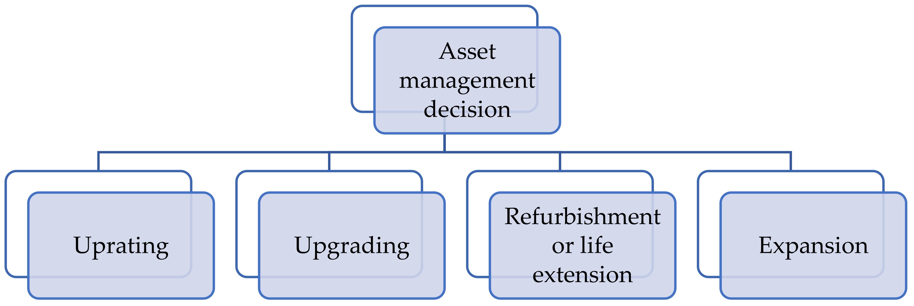
The importance of transmission line systems for both current and future transmission line systems has been established. Therefore, there have been rigorous works and research projects dedicated to increasing the transmission line system components. In this regard, four major asset management decisions, as illustrated in
Figure 1, are normally taken into consideration. However, the main concerns to be assessed for increasing the utilisation of existing transmission lines systems are economic and technical factors. According to CIGRE Technical Brochure 353, the guidelines to increase the utilisation of existing transmission lines will be influenced by the asset life expectancy, the load growth forecast, the planning horizon, the value of capital, cost–benefit analysis, economic optimisation, and other project constraints. As summarised in
Table 2, Malaysia’s national grid maximum demand showed an increment trend annually, and thus, it leads to an increase in load growth in the future.
Uprating is defined as increasing the electrical characteristics of a transmission line system in, for example, a requirement for higher electrical capacity or larger electrical clearances [
52]. Meanwhile, upgrading is defined as increasing the original mechanical and or electrical strengths for increased applied loads in increment weather and extremities such as wind, ice, and any load case combination, or improving electrical performance in conditions such as pollution or lightning performance. On the other hand, refurbishment is defined as the extensive renovation or repair of an item to restore the intended design’s working life. Life extension is an option of refurbishment, which does not result in the complete restoration of the originally designed working life [
56]. Finally, expansion is defined as increasing the functionality of transmission lines.
There are several uprating methods implemented throughout the world by either increasing the current carrying of its conductor or by increasing its operating voltage level, namely thermal uprating and voltage uprating [
57,
58]. According to [
18], it was revealed that thermal uprating techniques including installing higher capacity of conductors, additional conductors, and redesign led to high surge impedance; meanwhile voltage uprating techniques, for instance by increasing electrical strength and conductor attachment, involved an increase in the power transfer capability. In this study, voltage uprating is chosen, due to it being one of the most effective solutions and strategic approaches to asset management decisions. Previous work in [
2] revealed that voltage uprating delivered significantly higher power transfer capability, which occured due to it occuring less electrical losses rather than thermal uprating. In addition, it could be completed at a substantially lower cost than the new development of transmission lines, and it is considered to have a shorter lead time [
2,
15].There are numerous voltage uprating methods associated with techniques and processes that have been implemented all over the world. Generally, increasing voltage level will ultimately increase the transmission line capacity, potentially also increasing the consequences of a failure [
18]. However, the typical limiting and practical considerations of the voltage uprating method might be best considered on a case-by-case basis and will depend upon the location, environment, characteristics, and performances of the existing transmission line.
4. Mechanism for Voltage Uprating
The variety and number of methods and techniques adopted and implemented throughout the world to uprate transmission line systems are directly influenced by the considerable variation of transmission line system designs and construction methods employed [
59,
60]. Nevertheless, the uprating of the transmission line system generally fell into either increasing voltage capacity or thermal capacity.
Table 2 provides a list of the most common voltage uprating mechanisms, the associated methods, techniques, and processes, respectively. According to [
18,
61], there are two common techniques commonly used by electric utility operators to increase the voltage rating, either by increasing insulation strength or improving conductor air clearance.
Table 2.
Transmission line uprating mechanism [
18,
61].
Table 2.
Transmission line uprating mechanism [
18,
61].
| Mechanism | Method | Technique | Process |
|---|
| Increased voltage rating | Increased electrical clearance | Increasing insulation
electrical strength | |
| Improving conductor air clearance | |
The decision to increase the existing transmission line system will affect components and electrical parameters, as summarised in
Table 3. Techniques that comprise electrical insulation strength could affect electrical parameters such as lightning performance, EMF, radio, and audio interference [
62].
The selection of the appropriate method in uprating varies from case to case and is subject to the existing line’s location, characteristics, and performance [
2]. Utility operators around the world have chosen different techniques to increase the voltage capability of their transmission line systems. There are several studies associated with power transfer capability by implementing voltage uprating as the mechanism, summarised in
Table 4. As a result, the implemented techniques accomplished voltage uprating either by increasing conductor air clearance or by improving the electrical insulation strength of the existing transmission line system.
5. Electrical Clearances Requirement
The nature of the voltage stresses that a transmission line system had experienced power frequency, lightning, and switching overvoltages [
67,
68,
69,
70,
71,
72,
73,
74]. Both transient and power frequency voltage stresses appear in all shapes and with different amplitudes. Each type of transient and power frequency overvoltage may occur during most types of meteorological conditions, leading to differences in the flashover strength [
75].
Those overvoltages must be considered separately in identifying any possibility to assess the feasability of voltage uprating, which is necessary verification of the availability of electrical clearance. Therefore, the fundamental breakdown voltage characteristics were derived in order to evaluate the electrical clearance requirement for particular voltage levels that determine the required clearance envelope for power frequency, lightning, and switching overvoltages. According to [
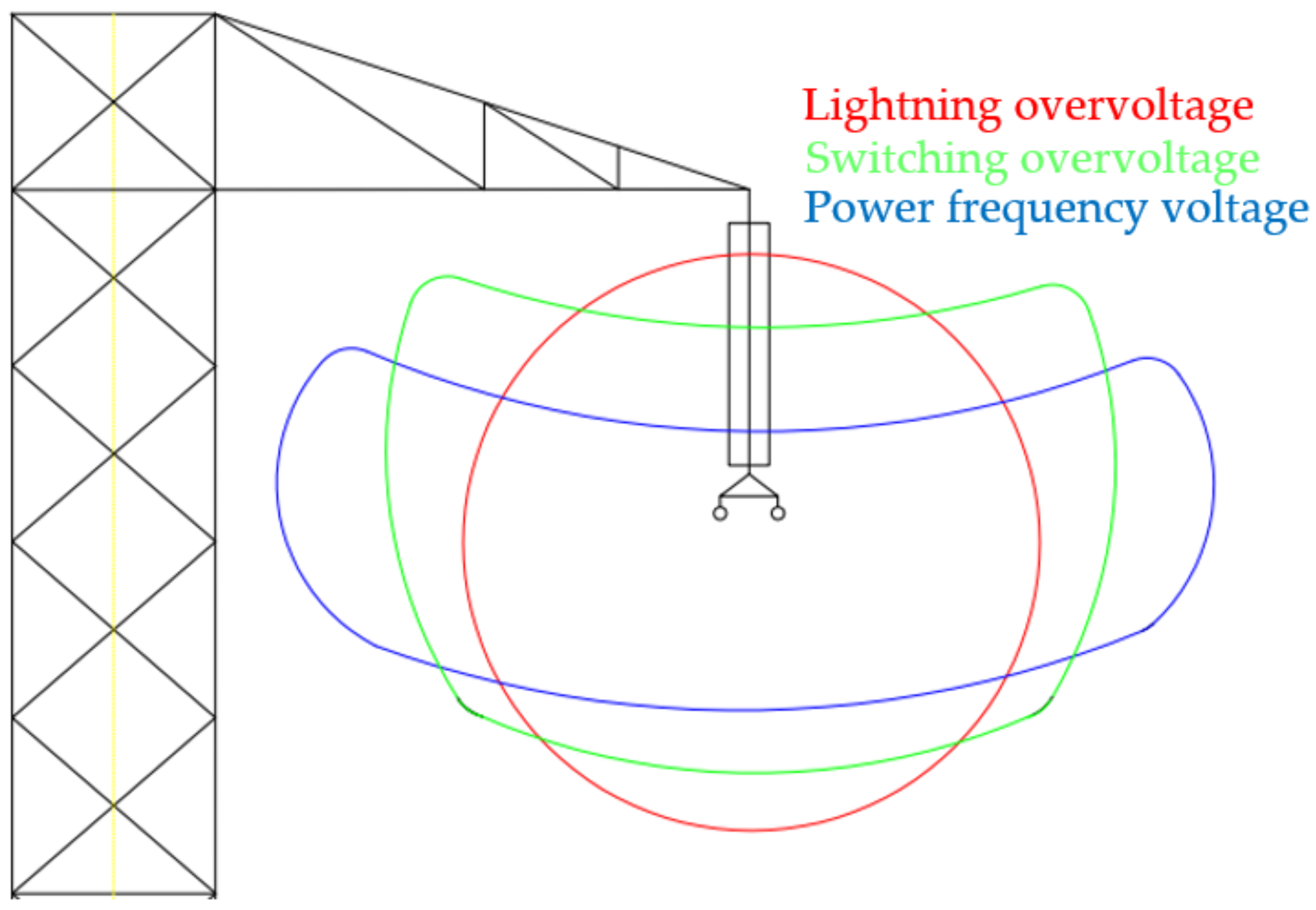
75], the voltage which the transmission line system can withstand are strongly influenced by the weather. In the case of lightning activities, its clearance envelopes are affected by the nature of the back flashover. There is a low possibility for the insulator swing angles to be prominent during the lightning activities. Thus, the electrical clearances for lightning activities could be neglected in favour of wind swing angles. Hence, the clearance envelope for lightning overvoltage is circular, as shown in
Figure 2 [
57,
76]. However, the geometry of electrical clearance envelopes is influenced by the insulator swing angle due to wind conditions, in the case of both power frequency and switching activities [
57].
According to [
75], a switching surge is an overvoltage occurring on the power system as the result of a perturbation caused by switching activities. Therefore, a switching surge voltage could travel a long distance along with the transmission line system, leading to slight attenuation. Thus, it contributes multiple stressors at the towers on the transmission line system [
57,
76]. There is a possibility that wind conditions and the resultant deviation swing angle and affect flashover can be significant. Hence, it could influence the electrical clearance envelope. This leads to a switching overvoltage envelope of elliptical shape, as shown in
Figure 2.
Power frequency voltage controls the design of insulation strings in contaminated conditions. It is essential to examine the decrements of insulation strength that may occur due to extreme swing angles and accumulation of contamination conditions. Additionally, the magnitude of power frequency voltage is much lower as compared with transient overvoltages. However, the electrical clearance between the phase and the tower structure once the phase and insulator string swing in conditions of extreme winds toward the tower structure or other phases may cause flashover due to reduction of clearance envelope [
77]. Therefore, the power frequency voltage clearance envelope is highly elongated to account for extreme wind swing angles, as shown in
Figure 2.
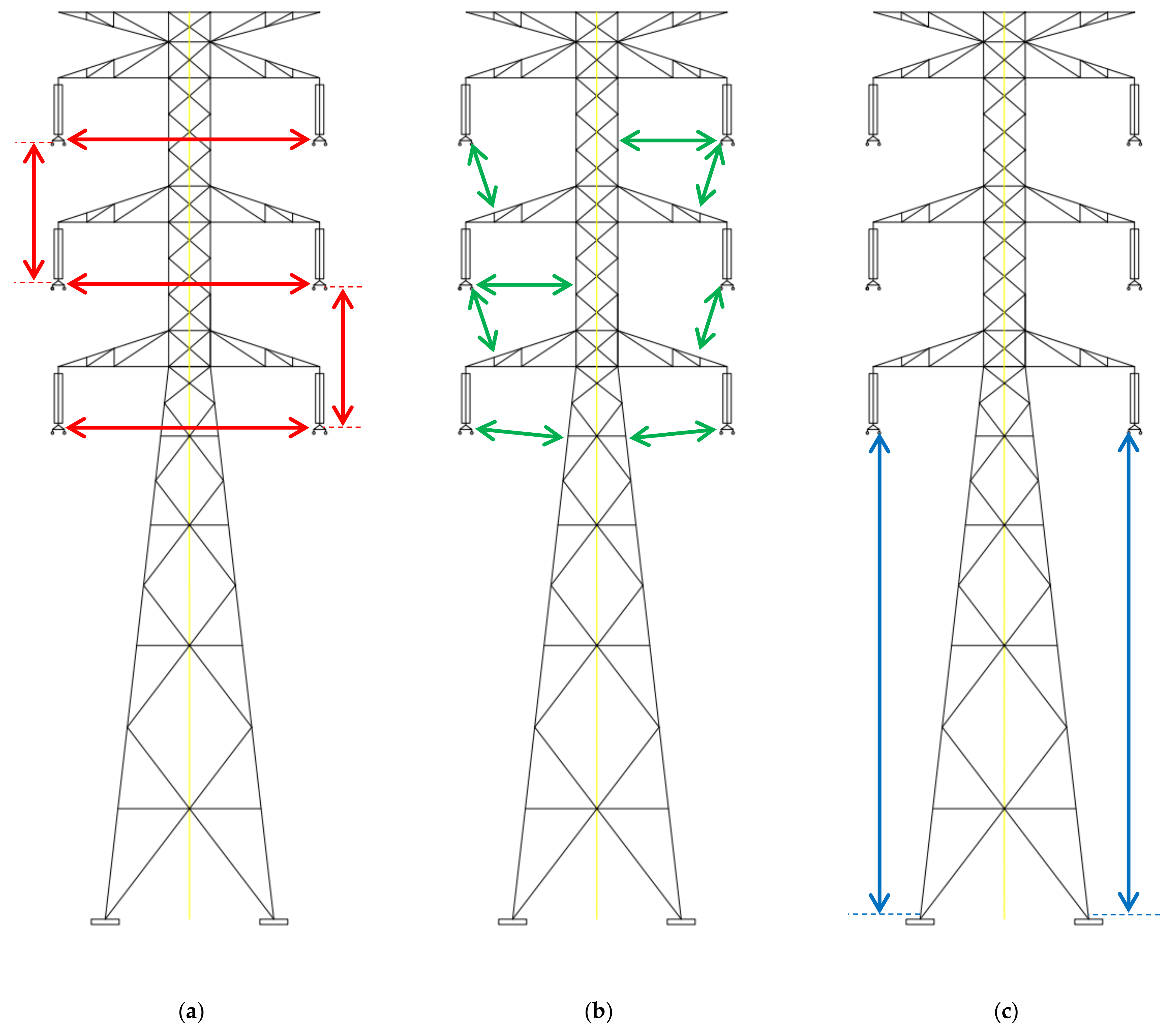
Figure 3 shows that the measurement is taken for phase-to-phase, phase-to-earth, and phase-to-ground. For clearance measurement, the phase-to-phase defines the distance between the phase conductor and another phase conductor, while phase-to-earth defines the distance between phase conductor and the body of a structure or steel crossarm, and phase-to-ground defines the distance between the lowest phase conductor and the structure base. The minimum air clearances required for each voltage level are given in IEC60071. In this study, the minimum electrical clearances during still air and wind conditions for the 275 kV transmission line system can be seen in
Table 5 and
Table 6.
6. Methodology of Voltage Uprating
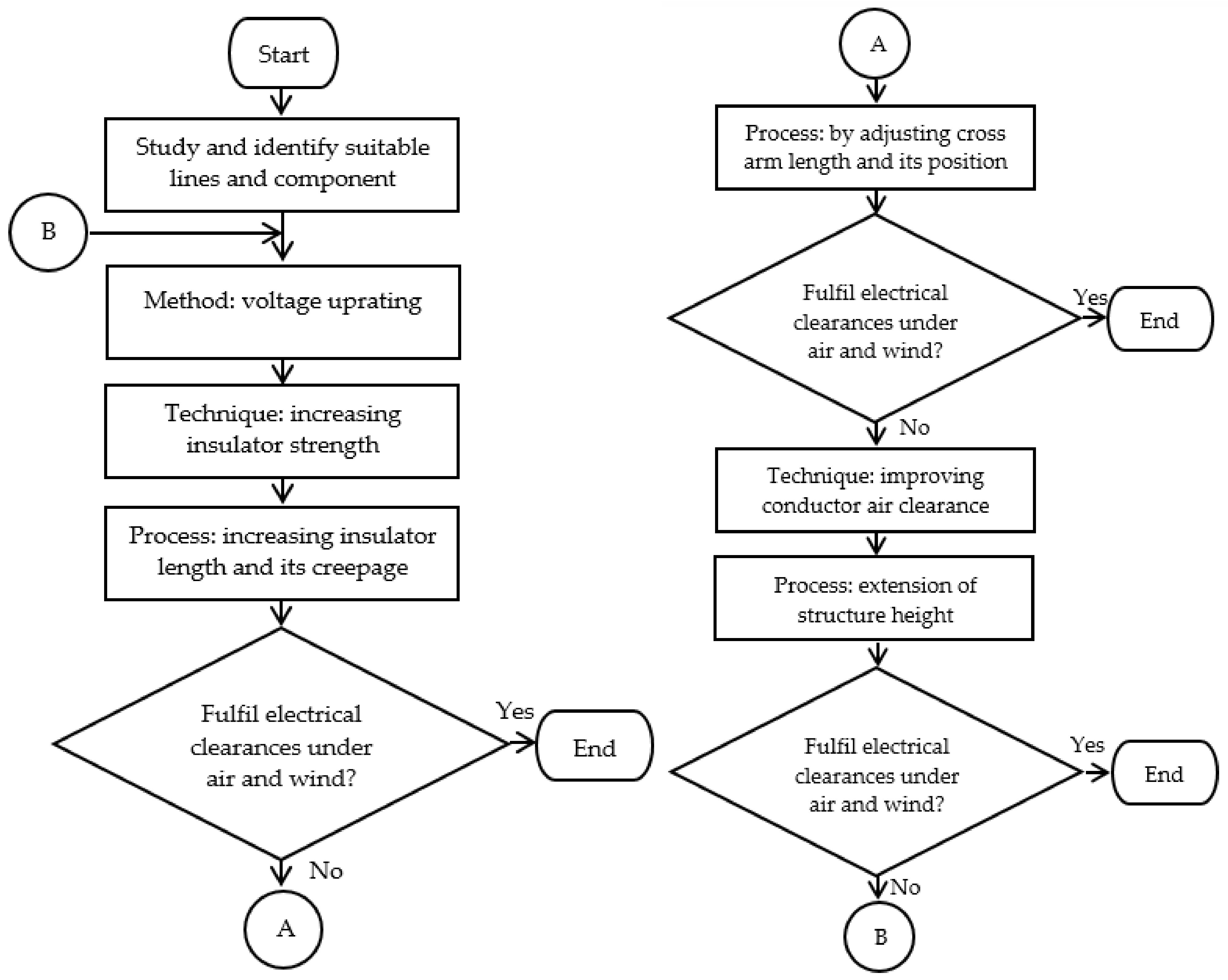
Figure 4 depicts the overall workflow in this voltage uprating for the transmission line system in Malaysia. The transmission line system chosen for this study involved was a 132 kV transmission line system. In order to achieve voltage uprating, associated techniques and processes against electrical clearance requirements were used in this study. The proposed techniques of voltage uprating for existing transmission were divided into two parts. The first proposed technique functioned by increasing insulator strength, while the second proposed technique worked by improving conductor air clearance. All proposed techniques and processes were measured to fulfil electrical clearances requirements under still air and windy conditions.
7. Descriptions of the 132 kV Transmission Line System in Malaysia
A 132 kV transmission line system (denoted as Line A-B) in Malaysia was chosen as the case study in this work. This line has experienced high ground flash density and recorded the most power supply trippings in peninsular Malaysia. The details of the transmission line under the case study are shown in
Table 7.
The transmission line system under the case study is a 112.81 km medium line with a double circuit 132 kV transmission line system.
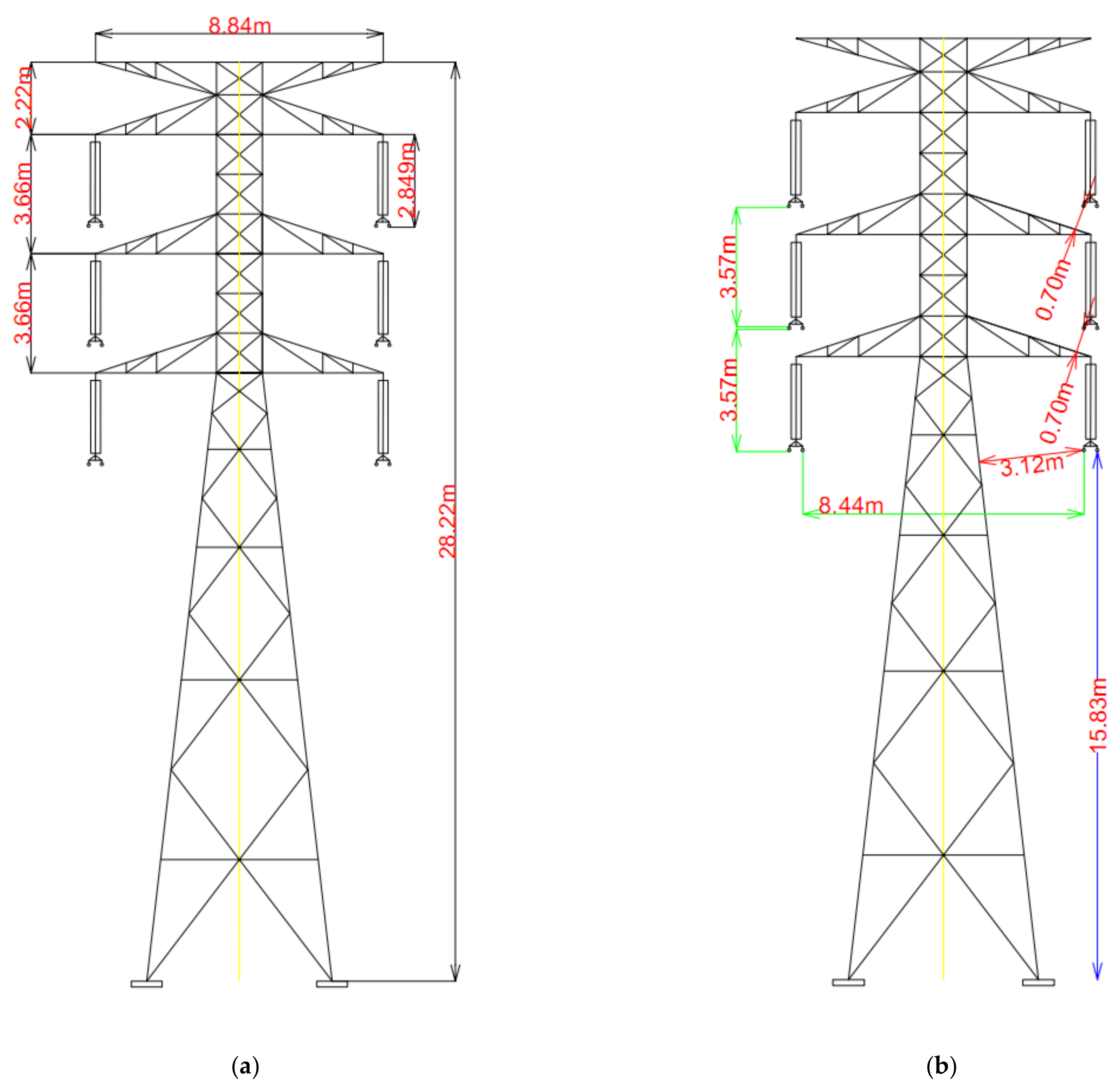
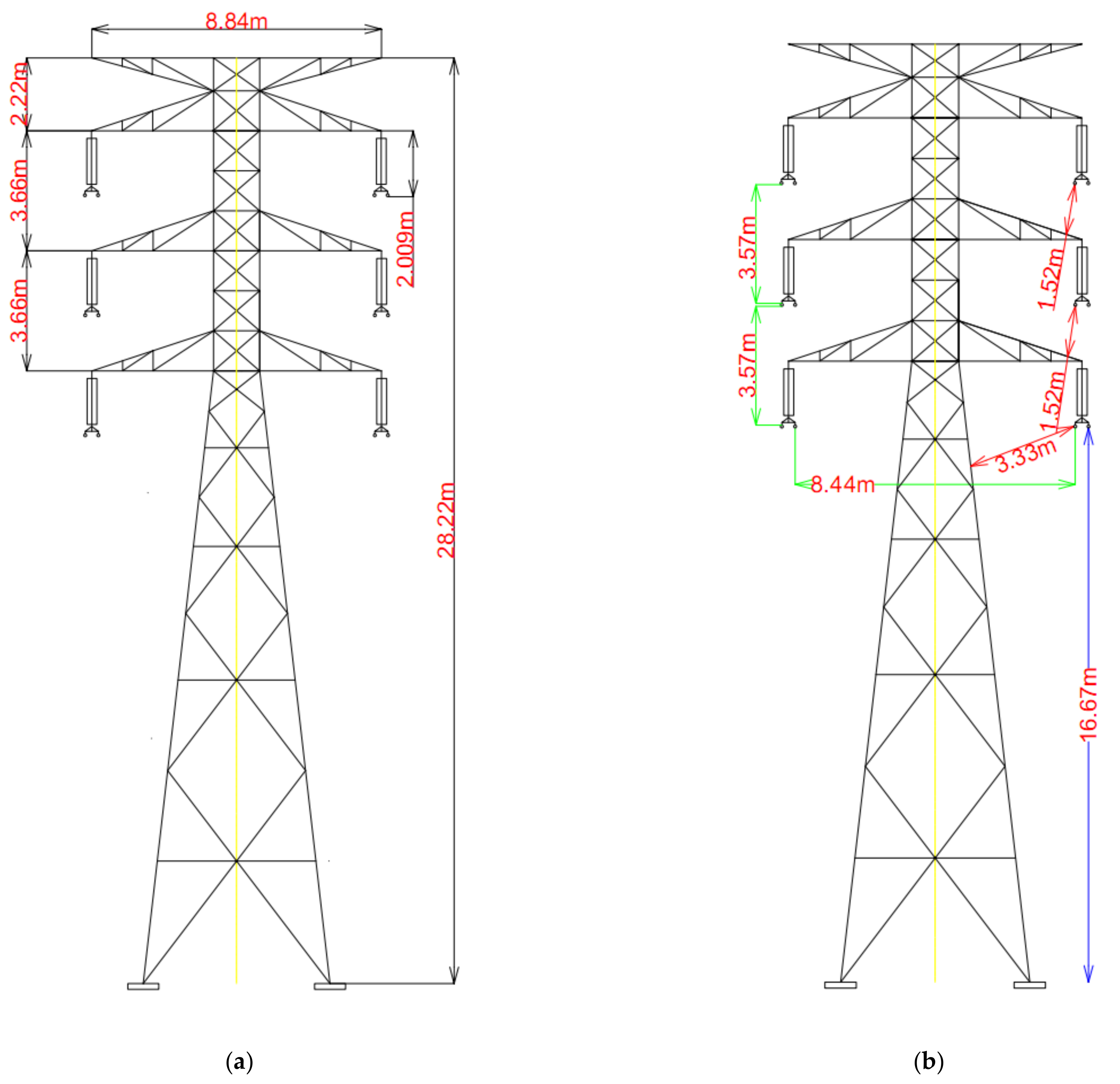
Figure 5a shows a typical 132 kV transmission tower construction model in Malaysia, known as type 23L steel lattice. The height of this lattice tower is 28.22 m, and the transmission line system is assumed to be located on flat terrain with a typical span length of 300 m. The line is strung with twin 300 mm
2 Aluminium Conductor Steel Reinforced (ACSR) code-named ‘Batang’, its outside diameter is 24.16 mm, and bundled conductors are separated at 400 mm each. Meanwhile, the earth wire is a single 160 mm
2 Optical Ground Wire (OPGW) for each circuit, and its outside diameter is 12.20 mm.
Typical suspension insulator string has ten toughened glass insulator discs and an overall string length of 2009 mm including fittings at the top and bottom of the string. The minimum electrical clearances for phase-to-phase, phase-to-earth, and phase-to-ground are 3.57 m, 1.52 m, and 16.67 m, respectively.
Figure 5b shows the details of electrical clearance under evaluation for a typical 132 kV transmission line system.
8. Voltage Uprating of the Existing 132 kV Transmission Line and Its Processes
8.1. Analysis Process—Preliminary
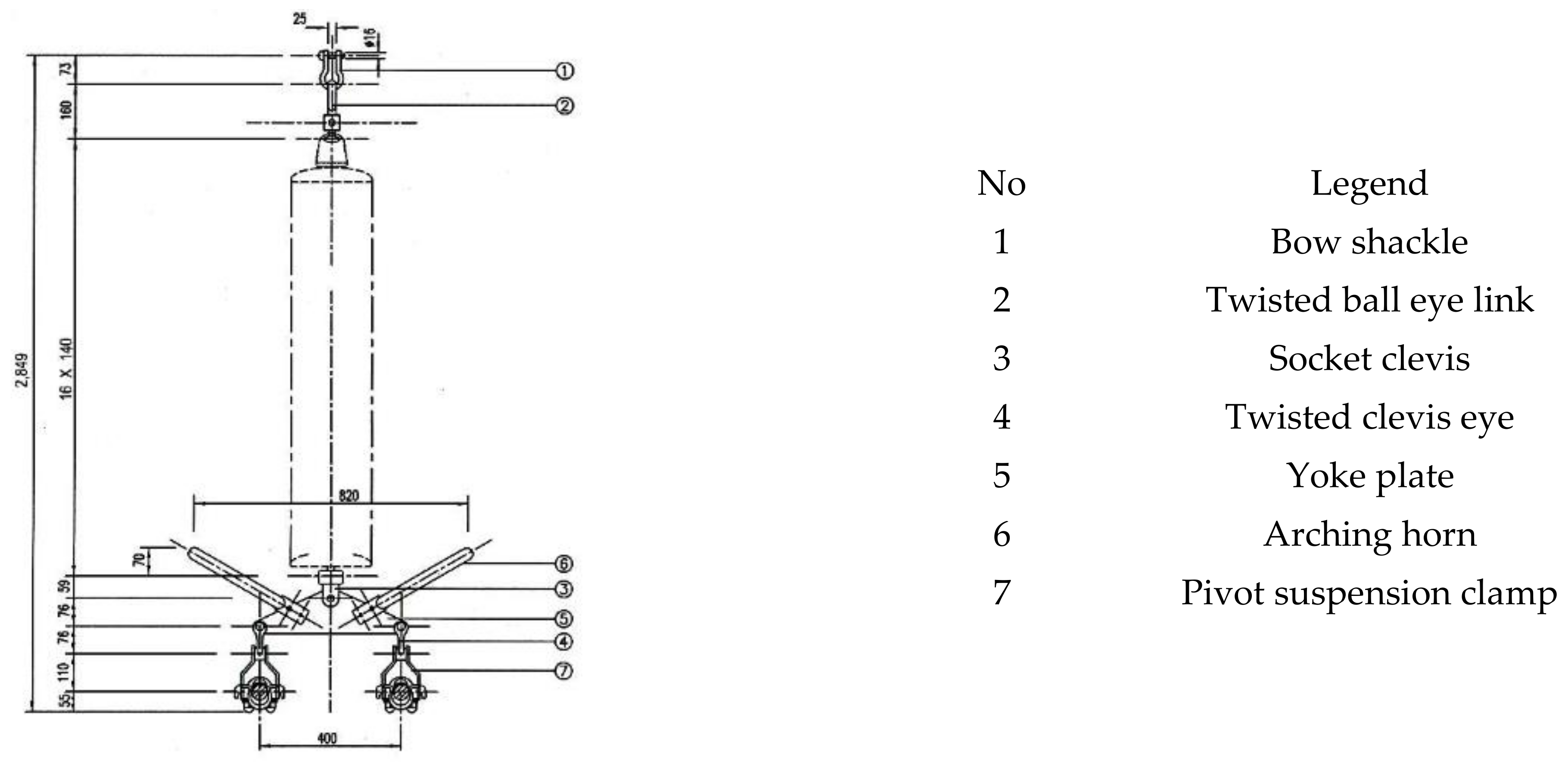
Figure 6 shows the 132 kV steel lattice tower with 275 kV suspension string of toughened glass discs insulator type. In Malaysia, the typical 275 kV suspension insulator string has 16 toughened glass discs and 2849 mm overall string length, including fittings at the top and bottom of the string.
Figure 7 shows details of 275 kV suspension insulator string construction.
The available phase-to-phase and phase-to-ground clearances in the existing 132 kV transmission line system in still air condition show that there are adequate electrical clearances between the phase-to-phase and phase-to-ground to uprate to a 275 kV transmission line system, as shown in
Table 8. However, the phase-to-earth clearance does not satisfy the electrical clearance requirement in still air.
8.2. Analysis Process—By Adjusting Insulator Length and Its Creepage
To fulfil the requirement of electrical clearance, 132 kV transmission towers were modified by adjusting insulator lengths and creepage distance. As summarised in
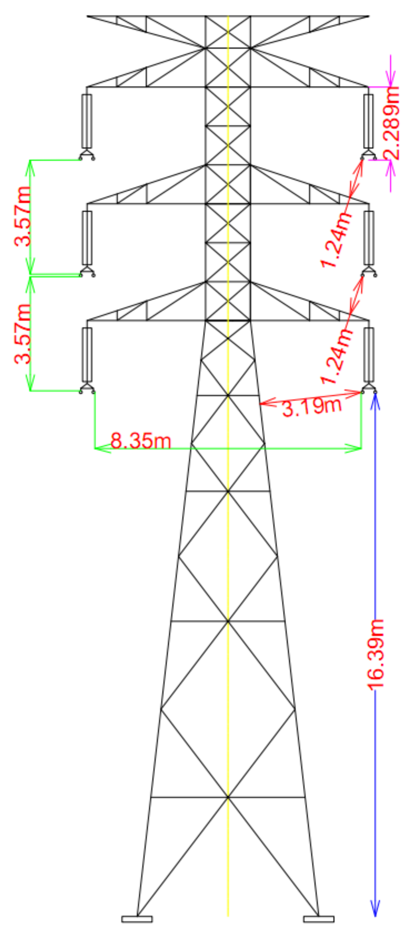
Table 9, the existing suspension string insulator length is 2240 mm, while the proposed suspension string insulator length is 1640 mm; however, its creepage distance is slightly more significant than the existing suspension string insulator. Besides these, the existing and proposed suspension string insulators had similar mechanical and electrical characteristics. Meanwhile, the proposed suspension insulator string has 12 toughened glass insulator discs and a 2289 mm overall string length, including fittings at the top and bottom of the string.
Figure 8 shows the available minimum phase-to-earth clearances of 1.24 m which are significantly not meeting the required phase-to-earth clearance of 1.80 m and 1.90 m in switching and lightning overvoltages for voltage uprating the 275 kV transmission line system.
Table 10 shows the minimum electrical clearances for the proposed model under still air condition.
8.3. Analysis Process—By Adjusting Crossarm Length and Its Position
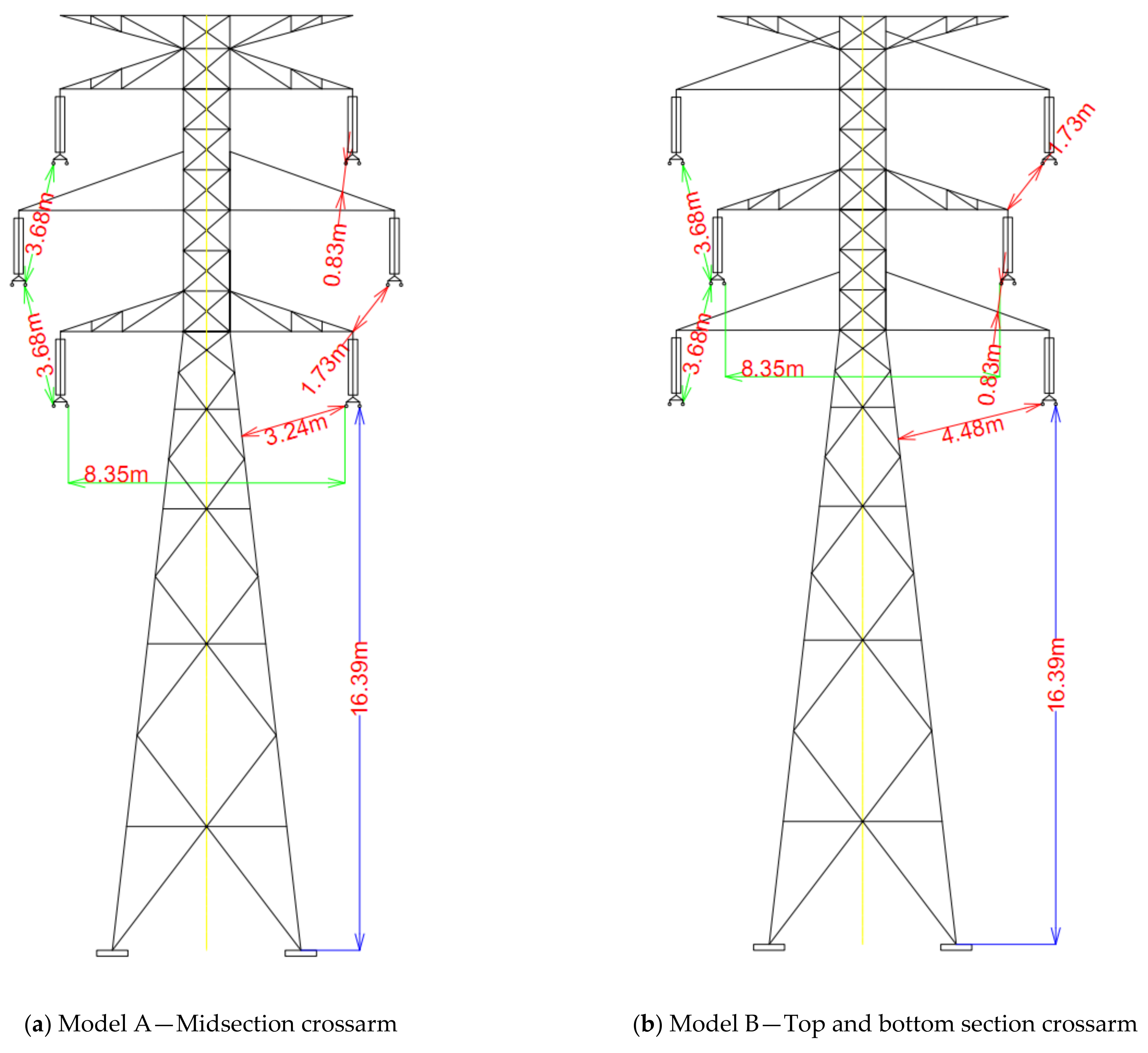
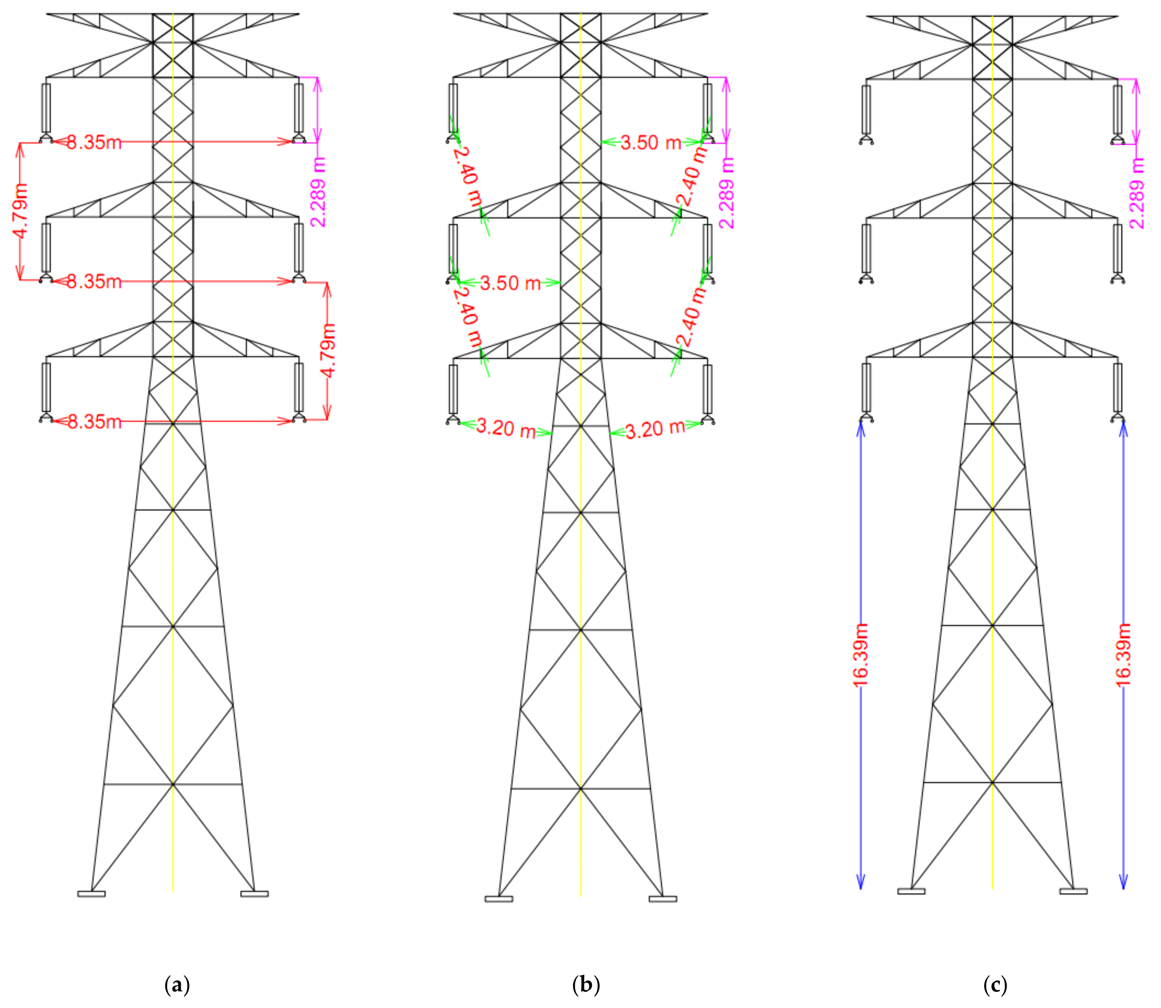
Two towers, namely Model A and Model B, were proposed to fulfil electrical clearances requirements for this uprating. Both models were structurally modified by adjusting cross-arm length and position, as shown in
Figure 9. The proposed cross-arm materials were made up of fiberglass composite. Model A and Model B showed that available minimum phase-to-earth clearances are 0.83 m and 0.83 m which are significantly not meeting the required phase-to-earth clearance of 1.80 m and 1.90 m in switching and lightning overvoltages for 275 kV transmission line system.
Table 11 shows the minimum electrical clearances for the proposed model under still air condition.
8.4. Analysis Process—By Improving Conductor Air Clearance
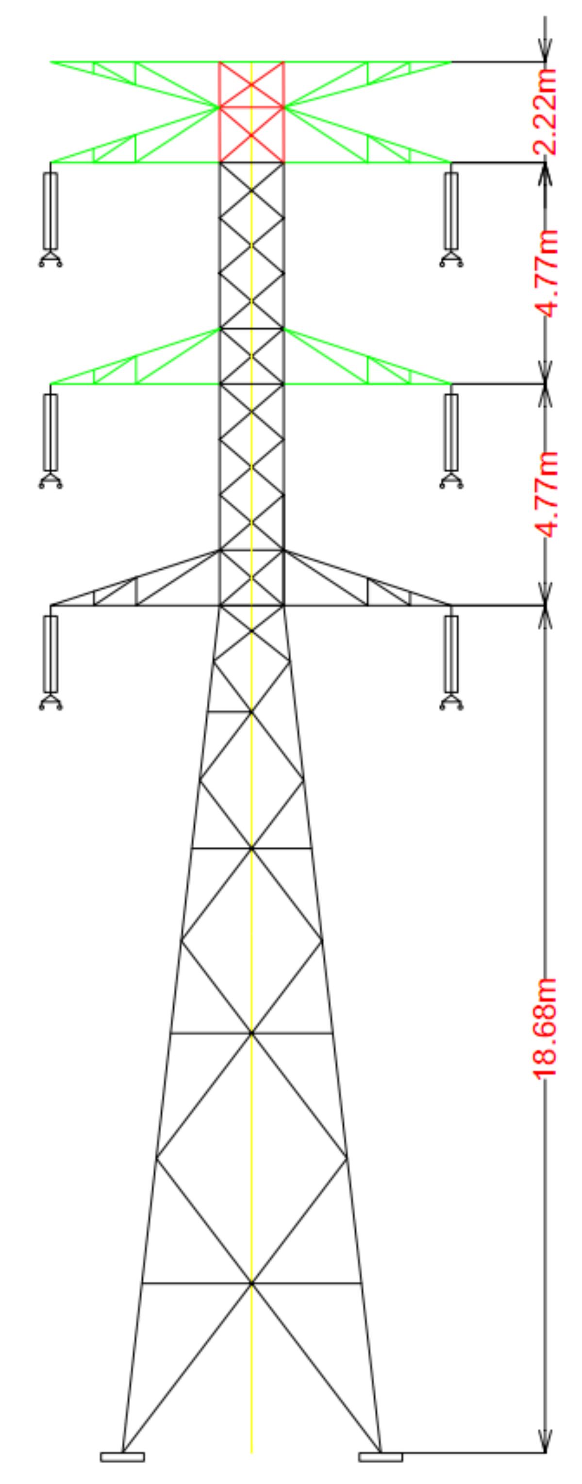
Minimal modification of the tower structure was made by increasing structure height to cater for electrical clearances under still air conditions. The top of the tower (redline) was added, expanding the structure height by 2.22 m. Meanwhile, the top, midsection, and shield crossarms (green line) were repositioned within the existing 132 kV transmission tower structure. The proposed 275 kV transmission height is 30.44 m, as can be seen in
Figure 10.
9. Analysis of Electrical Clearance on the Proposed Voltage Uprating Transmission Line
9.1. Under Still Air
Therefore, the minimum available electrical clearances between phase-to-earth, phase-to-phase, and phase-to-ground for the voltage 132 kV transmission line system under still air are now 2.40 m, 4.79 m, and 16.39 m, as shown in
Figure 11. Meanwhile,
Table 12 shows that the available minimum clearance requirement in the proposed 275kV transmission line system under still air condition, and it shows that there is adequate air for electrical clearances as per the requirements.
9.2. Under Normal and Extreme Wind Conditions
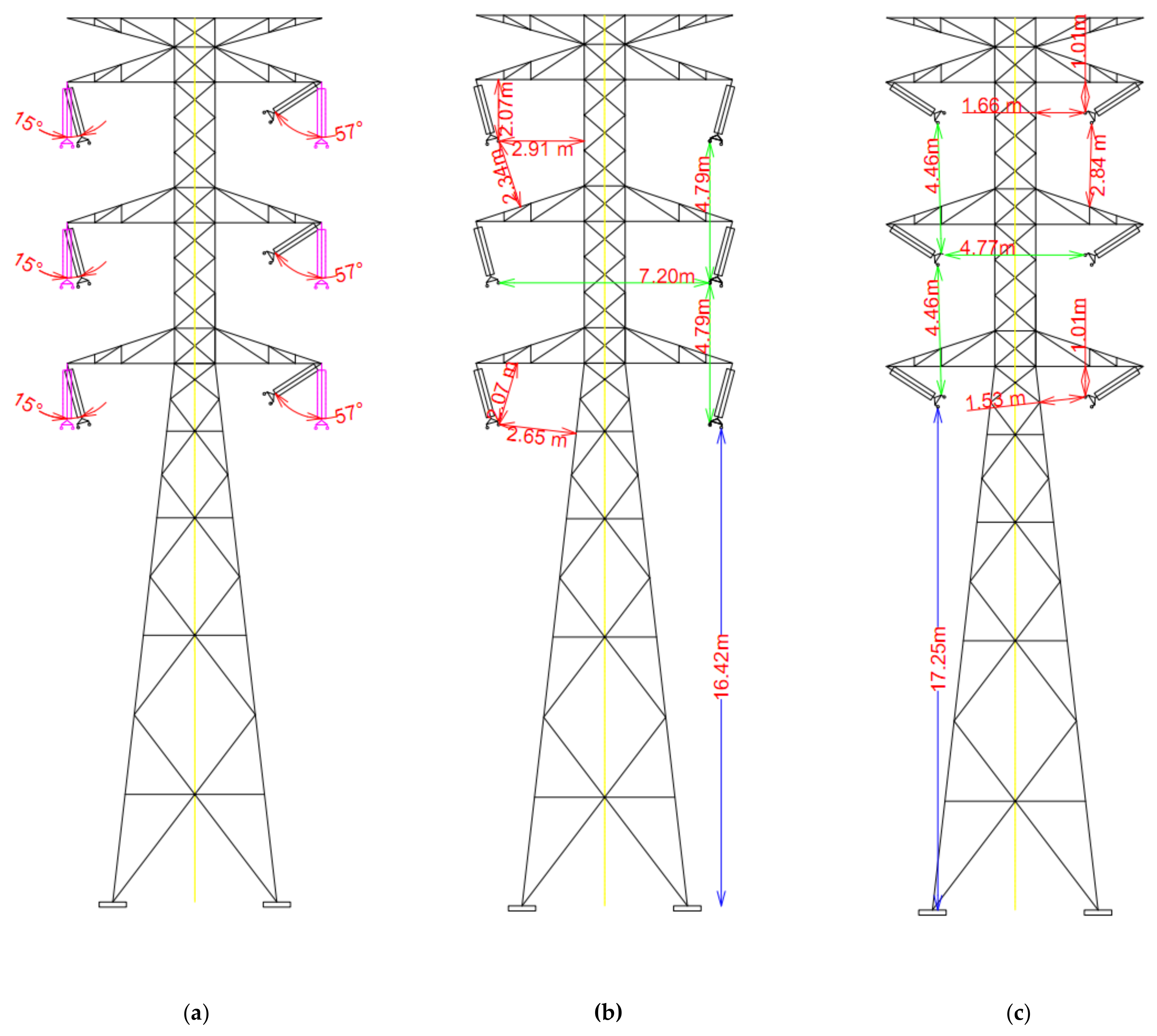
Figure 12 shows the air of electrical clearances during the normal swing and extreme swing. The normal swing angle is 15°, and the extreme swing angle is 57°. During normal wind conditions, the minimum available phase-to-earth, phase-to-phase, and phase-to-ground clearances are 2.07 m, 4.79 m, and 16.42 m, respectively. Meanwhile, under extreme wind conditions, the minimum available phase-to-earth, phase-to-phase, and phase-to-ground clearances during normal wind load are 1.01 m, 4.46 m, and 17.25 m, respectively. It can be seen that the available clearances are sufficient to operate at a 275 kV transmission line system, as shown in
Table 13.
10. Electrical Parameters and Environmental Impact of the Proposed Voltage Uprating
There are various environmental impacts due to transmission lines in-services, such as risks to the health and safety of the public and workers. In general, transmission lines are electric and magnetic field producers in their vicinity. The high voltage of lines generate an electric field, while the current flowing through high voltage lines generates a magnetic field [
18]. Thus, in this study, it is clearly shown that the voltage uprating could be a significant concern due to the changes in the electric and magnetic field.
Therefore, the proposed model of the existing 132 kV transmission lines takes into consideration the potential changes to the electric and magnetic field limitation by fulfilling statutory and safety regulations. According to [
18], several parameters, such as the electric field, magnetic field, radio interference, and audio noise produced around the transmission lines, are influenced by the operations of the voltage, clearances, conductor spacing, height, cross-section, and bundle.
Table 14 shows the effect parameters are due to transmission lines’ adjustments. Thus, two main elements are further analysed to assess the effects of its electrical parameters, including phase-to-phase clearance and conductor height above ground.
In Malaysia, the Malaysian Nuclear Agency (MAA) and Malaysia Standard (MS) specify guidelines for limiting exposure to time-varying electric, magnetic and electromagnetic fields and the majority of the national standards have adopted the recommendations of the guidelines issued by an International Commission on Non-Ionizing Radiation Protection (ICNIRP) [
83,
84,
85]. Therefore, the permissible exposure limits in terms of electric and magnetic fields are stipulated in terms of limiting the exposure of the general public and works to electric and magnetic fields.
Table 15 shows the exposure limits of electric and magnetic fields applicable in Malaysia.
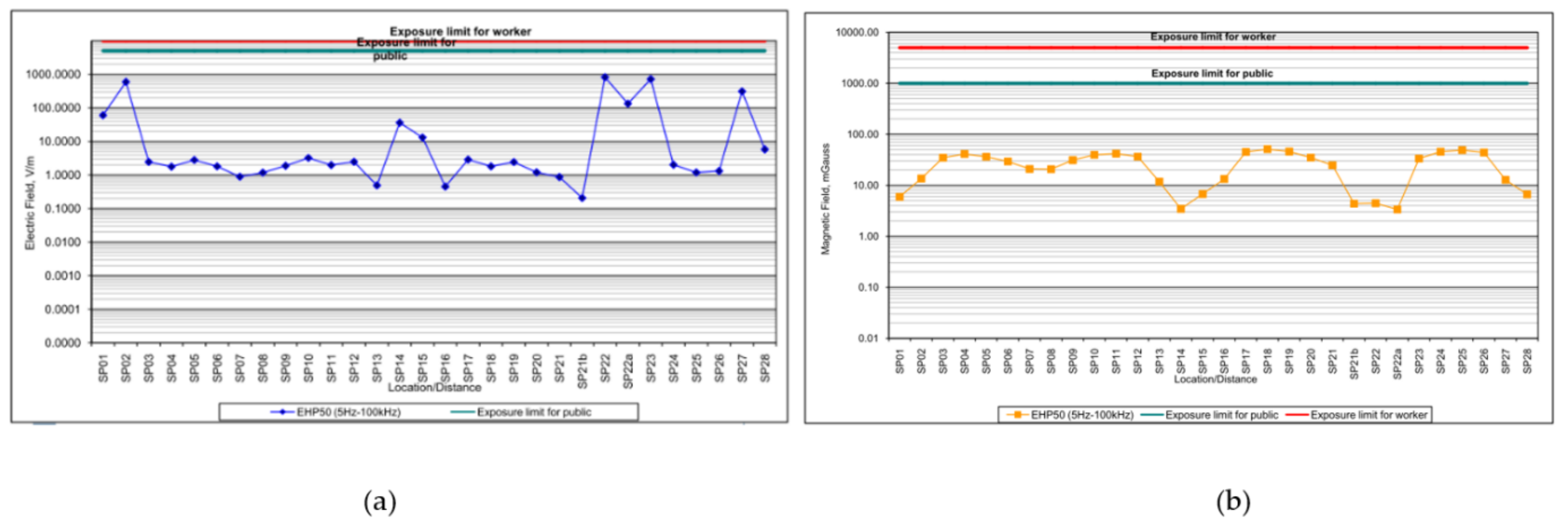
The MAA has measured the electric and magnetic fields at a typical 275 kV transmission line (Bandar Seri Putra, Selangor) and upon measuring both the phase-to-phase and phase-to-ground clearances, it was found that the typical 275 kV transmission produced electric and magnetic fields lower than the exposure limit both for the public and for workers [
84].
Figure 13 shows that the measured values of the electric and magnetic fields for several towers are quite lower than the exposure limits of the public and workers.
In this study, the electrical parameters (i.e., electric field, etc.) were not significantly affected by the phase conductor’s height from the ground (phase-to-ground), even when the voltage uprating tower model had experienced structural modification. This is due to the fact that the tower adaptation only involved the shield, top, and mid-section crossarm being repositioned, as shown in
Figure 10. In addition, the proposed voltage uprating transmission line shown that the minimum available clearance of phase-to-ground under still air condition is 16.39 m, which is double the required minimum clearance of 7.0 m needed for 275 kV transmission line operation. It is believed that the proposed voltage uprating transmission line fulfils statutory and safety regulations.
Since the level of voltage increase from 132 kV to 275 kV, it was found that there is a slight reduction of the electrical clearance (phase-to-phase) for the proposed voltage uprating transmission line. The minimum available clearance of phase-to-phase is 4.79 m, as summarised in
Table 12. Meanwhile, for the typical 275 kV transmission line in Malaysia, the minimum available clearance of phase-to-phase under still air condition is 5.55 m. There is a slight percentage of the difference between phase-to-phase for proposed voltage uprating transmission line and the typical 275 kV transmission line in Malaysia is 14%. However, there is should be sufficient phase-to-phase clearance for a maximum load operation, which is almost double the required minimum clearance of 2.6 m (for switching overvoltages) needed for 275 kV transmission line operation. Therefore, it is anticipated that the electric and magnetic fields do not affect the proposed voltage uprating line, even when it has experienced a decrement of phase-to-phase clearance. It is believed that the proposed voltage uprating line is considered in safety and margin design and this could not lead to any risks for the safety and health of the public or of workers.
11. Conclusions
Voltage uprating is one of the best options to increase the power transfer capability of the existing transmission line system. An electrical clearance analysis of the existing transmission is essential, as it determines the actual electrical clearance requirements, i.e., phase-to-phase, phase-to-earth, and phase-to-ground.
At the preliminary stage, the electrical clearance of the existing 132 kV transmission line system with 275 kV suspension string insulator is insufficient for voltage uprating study due to technical issues. It was shown that the phase-to-earth electrical clearances contributed to some concerning issues.
Based on the electrical clearances’ analysis and study, it was demonstrated that the techniques of adjusting insulator length and its creepage and improving conductor air clearance significantly help fulfil the required electrical clearances. As a result, it was shown that technical issues, i.e., phase-to-earth, can be overcome by increasing the phase-to-earth clearances, leading to the fulfilment of the requirement under still air and wind conditions. The voltage uprating of the 132 kV existing transmission line system requires only minimal structure modification but is able to gain substantial economic viability compared to having a whole new development of 275 kV transmission line system. Thus, it clearly helps to provide better and more sustainable solutions for asset management and power system operation in optimising the grid transfer capability for utilities.
Author Contributions
Conceptualization, S.F.M.N. and M.Z.A.A.K.; resources, A.M.A. and M.S.A.R.; writing—original draft preparation, S.F.M.N.; writing—review and editing, S.F.M.N., M.Z.A.A.K., M.O. and N.M.Z.; supervision, M.Z.A.A.K., A.M.A. and M.O.; funding acquisition, M.Z.A.A.K., A.M.A. and M.O. All authors have read and agreed to the published version of the manuscript.
Funding
The authors would like to thank Universiti Tenaga Nasional for the BOLD Scholarship. Special thanks to the Tenaga Nasional Berhad (Grid Maintenance) team for kindly supporting us by providing data.
Institutional Review Board Statement
Not applicable.
Informed Consent Statement
Not applicable.
Data Availability Statement
Not applicable.
Acknowledgments
Not applicable.
Conflicts of Interest
The authors declare no conflict of interest and the funders had no role in the design of the study; in the collection, analyses, or interpretation of data; in the writing of the manuscript, or in the decision to publish the results.
References
- Ntuli, M.; Xezile, R.; Mbuli, N.; Pretorius, J.H.C.; Motsoeneng, L. Increasing the capacity of transmission lines via current uprating: An updated review of benefits, considerations and developments. In Proceedings of the 2016 Australasian Universities Power Engineering Conference, Brisbane, Australia, 25–28 September 2016. [Google Scholar]
- Bhattarai, R.; Haddad, A.; Griffiths, H.; Harid, N. Voltage uprating of overhead transmission lines. In Proceedings of the 45th International Universities Power Engineering Conference UPEC2010, Cardiff, UK, 31 August–3 September 2010; pp. 1–6. [Google Scholar]
- Brignone, M.; Mestriner, D.; Procopio, R.; Piantini, A.; Rachidi, F. Evaluation of the mitigation effect of the shield wires on lightning induced overvoltages in MV distribution systems using statistical analysis. IEEE Trans. Electromagn. Compat. 2017, 60, 1400–1408. [Google Scholar] [CrossRef]
- Buijs, P.; Bekaert, D.; Cole, S.; Van Hertem, D.; Belmans, R. Transmission investment problems in Europe: Going beyond standard solutions. Energy Policy 2011, 39, 1794–1801. [Google Scholar] [CrossRef] [Green Version]
- Lobry, J.; Guery, D. Theoretical study of dielectric breakdown in a new composite core HTLS conductor. IEEE Trans. Power Deliv. 2012, 27, 1862–1867. [Google Scholar] [CrossRef]
- Albizu, I.; Mazon, A.J.; Zamora, I. Methods for increasing the rating of overhead lines. In Proceedings of the 2005 IEEE Russia Power Tech, St. Petersburg, Russia, 27–30 June 2005; pp. 1–6. [Google Scholar]
- Albermani, F.; Mahendran, M.; Kitipornchai, S. Upgrading of transmission towers using a diaphragm bracing system. Eng. Struct. 2004, 26, 735–744. [Google Scholar] [CrossRef] [Green Version]
- Mateescu, E.; Marginean, D.; Gheorghita, G.; Dragan, E.; Gal, S.I.A.; Matea, C. Uprating a 220 kV double circuit transmission line in Romania; study of the possible solutions, technical and economic comparison. In Proceedings of the 2009 IEEE Bucharest PowerTech, Bucharest, Romania, 28 June–2 July 2009; pp. 1–7. [Google Scholar]
- Abd-Elaal, E.-S.; Mills, J.; Ma, X. A review of transmission line systems under downburst wind loads. J. Wind. Eng. Ind. Aerodyn. 2018, 179, 503–513. [Google Scholar] [CrossRef]
- Orawski, G. Overhead lines—The state of the art. Power Eng. J. 1993, 7, 221–231. [Google Scholar] [CrossRef]
- Tenaga, S. The Malaysian Grid Code; Energy Commision: Putrajaya, Malaysia, 2013; pp. 1–436. [Google Scholar]
- Jeromin, I.; Balzer, G.; Backes, J.; Huber, R. Life Cycle Cost Analysis of transmission and distribution systems. In Proceedings of the CIRED 20th International Conference on Electricity Distribution, Prague, Czech Republic, 8–11 June 2009; pp. 8–11. [Google Scholar]
- Jeromin, I.; Balzer, G.; Backes, J.; Huber, R. Life Cycle Cost Analysis of transmission and distribution systems. In Proceedings of the 2009 IEEE Bucharest PowerTech Innovative Ideas Toward the Electrical Grid of the Future, Bucharest, Romania, 28 June–2 July 2009; pp. 1–6. [Google Scholar]
- Velásquez, R.M.A.; Lara, J.V.M. Methodology for Overhead Line Conductor Remaining Life. In Proceedings of the 2018 IEEE PES Transmission & Distribution Conference and Exhibition—Latin America., Lima, Peru, 18–21 September 2018; pp. 1–5. [Google Scholar]
- Shankle, D. Incremental Voltage Uprating of Transmission Lines. IEEE Trans. Power Appar. Syst. 1971, 90, 1791–1795. [Google Scholar] [CrossRef]
- Manickam, R.; Palaniappan, S.N. Upgrading transmission line capability by AC–DC conversion. Comput. Electr. Eng. 2018, 68, 616–628. [Google Scholar] [CrossRef]
- Larruskain, D.M.; Zamora, I.; Abarrategui, O.; Aginako, Z. Conversion of AC distribution lines into DC lines to upgrade transmission capacity. Electr. Power Syst. Res. 2011, 81, 1341–1348. [Google Scholar] [CrossRef]
- WG.B2.13. Guidelines for Increased Utilization of Existing Overhead Transmission Lines; The International Council on Large Electric Systems (CIGRE): Paris, France, 2008; pp. 1–170. [Google Scholar]
- Filipović-Grčić, B.; Uglešić, I.; Pavić, I. Application of line surge arresters for voltage uprating and compacting of overhead transmission lines. Electr. Power Syst. Res. 2016, 140, 830–835. [Google Scholar] [CrossRef]
- Mbuli, N.; Xezile, R.; Motsoeneng, L.; Ntuli, M.; Pretorius, J.-H. A literature review on capacity uprate of transmission lines. Electr. Power Syst. Res. 2019, 170, 215–221. [Google Scholar] [CrossRef]
- Bezerr, J.; Silv, A.; Lins, Z.; Junior, J.; Santos, E. Field validation of a new model for uprating transmission lines. Electr. Power Syst. Res. 2016, 134, 30–37. [Google Scholar] [CrossRef]
- Florea, G.A.; Florea, M.; Tibuliac, S.; Vaju, M.; Oltean, M.; Mateescu, E. Upgrading the Romanian 400 kV lines with 2 and 3 subconductors per phase to reduce the risk of galloping occurance and the galopping amplitudes by the installation of torsional dampers and detuners, live-line procedures. In Proceedings of the 2016 IEEE PES 13th International Conference on Transmission & Distribution Construction, Operation, & Live-Line Maintenance, Columbus, OH, USA, 12 October 2016; Volume 74, pp. 14–18. [Google Scholar]
- Dupin, R.; Kariniotakis, G.; Michiorri, A. Overhead lines Dynamic Line rating based on probabilistic day-ahead forecasting and risk assessment. Int. J. Electr. Power Energy Syst. 2019, 110, 565–578. [Google Scholar] [CrossRef]
- Nuchprayoon, S.; Chaichana, A. Performance Comparison of Using ACSR and HTLS Conductors for Current Uprating of 230-kV Overhead Transmission Lines. In Proceedings of the 2018 IEEE International Conference on Environment and Electrical Engineering and 2018 IEEE Industrial and Commercial Power Systems Europe (EEEIC/I&CPS Europe), Palermo, Italy, 12–15 June 2018; pp. 1–5. [Google Scholar]
- Ferrari, J.C.S.; de Araújo, A.R.J.; Kurokawa, S. Analysis of the voltage profile in transmission lines operating with injected third harmonic voltages. Int. J. Electr. Power Energy Syst. 2020, 125, 106538. [Google Scholar] [CrossRef]
- Coletta, G.; Vaccaro, A.; Villacci, D. A review of the enabling methodologies for PMUs-based dynamic thermal rating of power transmission lines. Electr. Power Syst. Res. 2017, 152, 257–270. [Google Scholar] [CrossRef]
- Kishore, T.; Singal, S. Optimal economic planning of power transmission lines: A review. Renew. Sustain. Energy Rev. 2014, 39, 949–974. [Google Scholar] [CrossRef]
- Naidoo, P. Investigations into the upgrading of existing transmission lines from HVAC to HVDC. In Proceedings of the 2011 IEEE Power and Energy Society General Meeting, Detroit, MI, USA, 24–28 July 2011; pp. 1–4. [Google Scholar] [CrossRef]
- Kopsidas, K.; Rowland, S.M.; Baharom, M.N.R.; Cotton, I. Power transfer capacity improvements of existing overhead line systems. In Proceedings of the 2010 IEEE International Symposium on Electrical Insulation, San Diego, CA, USA, 6–9 June 2010; pp. 1–5. [Google Scholar] [CrossRef] [Green Version]
- Kopsidas, K.; Rowland, S. Evaluating opportunities for increasing power capacity of existing overhead line systems. IET Gener. Transm. Distrib. 2011, 5, 1–10. [Google Scholar] [CrossRef] [Green Version]
- Marginean, D.; Mateescu, E.; Wechsler, H.; Florea, G.; Matea, C. Transforming existing 220 kV double circuit line into 400 kV single circuit line in Romania. In Proceedings of the 2011 IEEE PES 12th International Conference on Transmission and Distribution Construction, Operation and Live-Line Maintenance (ESMO), Providence, RI, USA, 16–19 May 2011; pp. 1–6. [Google Scholar]
- Daconti, J.; Lawry, D. Increasing power transfer capability of existing transmission lines. In Proceedings of the 2003 IEEE PES Transmission and Distribution Conference and Exposition, Dallas, TX, USA, 7–12 September 2003. [Google Scholar] [CrossRef]
- Ahmed, U.; Saqib, M.A. Prospect of voltage uprating of a conservatively designed EHV transmission line. Electr. Power Syst. Res. 2020, 182, 106203. [Google Scholar] [CrossRef]
- WG. B2.51. Guide to Overall Line Design; The International Council on Large Electric Systems (CIGRE): Paris, France, 2015; pp. 1–106. [Google Scholar]
- Riba, J.R.; Bogarra, S.; Gómez-Pau, Á.; Moreno-Eguilaz, M. Uprating of transmission lines by means of HTLS conductors for a sustainable growth: Challenges, opportunities, and research needs. Renew. Sustain. Energy Rev. 2020, 134, 110334. [Google Scholar] [CrossRef]
- IEEE Power and Energy Society. IEEE Guide for the Installation of Overhead Transmission Line Conductors; IEEE Standard 524; IEEE Power and Energy Society: New York, NY, USA, 2016; pp. 1–162. [Google Scholar]
- WG.B2.43. Guide for Thermal Rating Calculations of Overhead Lines; The International Council on Large Electric Systems (CIGRE): Paris, France, 2014; pp. 1–95. [Google Scholar]
- Sun, X.; Luh, P.B.; Cheung, K.; Guan, W. Probabilistic forecasting of dynamic line rating for over-head transmission lines. In Proceedings of the 2015 IEEE Power & Energy Society General Meeting, Denver, CO, USA, 26–30 July 2015; pp. 1–5. [Google Scholar]
- Zamora, I.; Mazon, A.; Eguía, P.; Criado, R.; Alonso, C.; Iglesias, J.; Saenz, J. High-temperature conductors: A solution in the uprating of overhead transmission lines. In Proceedings of the 2001 IEEE Porto Power Tech Proceedings, Porto, Portugal, 10–13 September 2001. [Google Scholar]
- Jamnani, J.; Patel, V. Surge Impedance Loading level enhancement of 765 kV long EHV AC line through bundle configurations. In Proceedings of the 2016 Biennial International Conference on Power and Energy Systems: Towards Sustainable Energy, Bengaluru, India, 21–23 January 2016; pp. 1–5. [Google Scholar] [CrossRef]
- Ghassemi, M. High Surge Impedance Loading (HSIL) Lines: A Review Identifying Opportunities, Challenges, and Future Research Needs. IEEE Trans. Power Deliv. 2019, 34, 1909–1924. [Google Scholar] [CrossRef]
- Beryozkina, S. Evaluation Study of Potential Use of Advanced Conductors in Transmission Line Projects. Energies 2019, 12, 822. [Google Scholar] [CrossRef] [Green Version]
- Karimi, S.; Musilek, P.; Knight, A.M. Dynamic thermal rating of transmission lines: A review. Renew. Sustain. Energy Rev. 2018, 91, 600–612. [Google Scholar] [CrossRef]
- Ippolito, M.G.; Massaro, F.; Cassaro, C. HTLS Conductors: A Way to Optimize RES Generation and to Improve the Competitiveness of the Electrical Market—A Case Study in Sicily. J. Electr. Comput. Eng. 2018, 2018, 1–10. [Google Scholar] [CrossRef]
- WG.22.12. The Thermal Behavior of Overhead Conductors; The International Council on Large Electric Systems (CIGRE): Paris, France, 2002; pp. 1–46. [Google Scholar]
- WG.B2.12.3. Sag-Tension Calculation Methods for Overhead Lines; The International Council on Large Electric Systems (CIGRE): Paris, France, 2016; pp. 1–91. [Google Scholar]
- Ahmad, A.; Jin, Y.; Zhu, C.; Javed, I.; Akram, M.W. Investigating tension in overhead high voltage power transmission line using finite element method. Int. J. Electr. Power Energy Syst. 2019, 114, 105418. [Google Scholar] [CrossRef]
- Reddy, B.S.; Chatterjee, D. Performance evaluation of high temperature high current conductors. IEEE Trans. Dielectr. Electr. Insul. 2016, 23, 1570–1579. [Google Scholar] [CrossRef]
- Douglass, D.; Chisholm, W.; Davidson, G.; Grant, I.; Lindsey, K.; Lancaster, M.; Lawry, D.; McCarthy, T.; Nascimento, C.; Pasha, M.; et al. Real-Time Overhead Transmission-Line Monitoring for Dynamic Rating. IEEE Trans. Power Deliv. 2014, 31, 921–927. [Google Scholar] [CrossRef]
- Albizu, I.; Fernandez, E.; Alberdi, R.; Bedialauneta, M.T.; Mazon, A.J. Adaptive Static Line Rating for Systems with HTLS Conductors. IEEE Trans. Power Deliv. 2018, 33, 2849–2855. [Google Scholar] [CrossRef]
- Shivashankar, G.S. Poornima Overview of different overhead transmission line conductors. Mater. Today Proc. 2017, 4, 11318–11324. [Google Scholar] [CrossRef]
- Broschat, M. Transmission Line Uprating 115 kV to 230 kV Report on Operating Performance. IEEE Trans. Power Appar. Syst. 1972, PAS-91, 545–548. [Google Scholar] [CrossRef]
- Broschat, M.; Member, S. Compaction techniques applied to subtranmission line uprating 41.6 kV to 115 kV. IEEE Trans. Power Appar. Syst. 1981, 4, 1959–1965. [Google Scholar]
- Venkatesan, S.; Haddad, A.; Griffiths, H.; Harid, N.; Albano, M. Reducing air clearance requirements for voltage uprating of overhead line by use of line surge arresters. In Proceedings of the 2009 IEEE Conference on Electrical Insulation and Dielectric Phenomena, Virginia Beach, VA, USA, 18–21 October 2009; pp. 224–229. [Google Scholar] [CrossRef]
- Warmi, Y.; Michishita, K. Investigation of lightning tripouts on 150-kV transmission lines in West Sumatra in Indonesia. IEEJ Trans. Electr. Electron. Eng. 2016, 11, 671–673. [Google Scholar] [CrossRef]
- Braga, A.; Braga, M.; Da Veiga, D.; Moreira, I. Upgrading and refurbishment of an energized transmission line. In Proceedings of the 2000 IEEE 9th International Conference on Transmission & Distribution Construction, Operation & Live-Line Maintenance, Montreal, QC, Canada, 8–12 October 2002; pp. 11–20. [Google Scholar]
- Osborne, M.; Haddad, A. A Case Study on Voltage Uprating of Overhead Lines—Air Clearance Requirements. In Proceedings of the 45th International Universities Power Engineering Conference, Cardiff, UK, 31 August–3 September 2010; pp. 1–5. [Google Scholar]
- Kopsidas, K.; Rowland, S.M. Evaluation of potentially effective ways for increasing power capacity of existing overhead lines. In Proceedings of the 1st International Conference on Sustainable Power Generation and Supply, SUPERGEN ’09, Nanjing, China, 6–7 April 2009; pp. 1–7. [Google Scholar] [CrossRef]
- Carrington, R.J. New technologies for transmission line uprating. In Proceedings of the 1998 IEEE 8th International Conference on Transmission & Distribution Construction, Operation, & Live-Line Maintenance, Orlando, FL, USA, 6 August 2002. [Google Scholar] [CrossRef]
- Kiessling, F.; Nefzger, P.; Nolasco, J.F.; Kaintzyk, U. Overhead Power Lines, Planning Design Construction; Springer: New York, NY, USA, 2003; pp. 1–800. [Google Scholar]
- WG.B2.06. How Overhead Lines Are Re-Designed for Uprating/Upgrading; The International Council on Large Electric Systems (CIGRE): Paris, France, 2006; pp. 1–102. [Google Scholar]
- IEEE Power and Energy Society. IEEE Guide for Planning and Designing Transition Facilities between Overhead and Underground Transmission Lines; IEEE Stand.ard 1793; IEEE Power and Energy Society: New York, NY, USA, 2013; pp. 1–40. [Google Scholar]
- Berlijn, S.; Lundquist, J.; Gislason, S. Estimating the line performance of voltage upgraded lines. J. Chem. Inf. Model. 2013, 53, 1689–1699. [Google Scholar]
- Kikuchi, T.; Oba, W.; Kojima, Y.; Asano, Y. Compact transmission lines for increasing voltage while keeping existing equipment intact, The International Council on Large Electric Systems (CIGRE) Conference, Tokyo, Japan. 1998, p. 6. Available online: https://e-cigre.org/publication/223336-03_1998-compact-transmission-lines-for-increasing-voltage-while-keeping-existing-equipment-intact (accessed on 15 July 2021).
- Narain, S.; Muftic, D.; Jacobs, B.; Naidoo, P. Uprating of 275 kV Lines to 400 kV as Part of a Contingency Plan for Generation Integration. In Proceedings of the 2006 IEEE/PES Transmission & Distribution Conference and Exposition—Latin America, Caracas, Venezuela, 15–18 August 2006. [Google Scholar]
- Berlijn, S.; Halsan, K.A.; Olsen, A.T.; Runde, M.; Hinteregger, M.; Judendorfer, T.; Muhr, M. Voltage upgrading—An insulation coordination challenge. In Proceedings of the 2011 IEEE Trondheim PowerTech, Trondheim, Norway, 19–23 June 2011. [Google Scholar]
- Cummins, K.; Krider, E.; Malone, M. The US National Lightning Detection Network/sup TM/ and applications of cloud-to-ground lightning data by electric power utilities. IEEE Trans. Electromagn. Compat. 1998, 40, 465–480. [Google Scholar] [CrossRef] [Green Version]
- IEEE Power and Energy Society. IEEE Guide for Improving the Lightning Performance of Electric Power Overhead Distribution Lines; IEEE Standard 1410; IEEE Power and Energy Society: New York, NY, USA, 2004; pp. 1–50. [Google Scholar]
- Hamza, A.; Ghania, S.M.; Emam, A.; Shafy, A.S. Failure risk analysis under switching surges in power transmission systems. Electr. Power Syst. Res. 2018, 166, 190–198. [Google Scholar] [CrossRef]
- Bakar, A.H.A.; Talib, D.N.A.; Mokhlis, H.; Illias, H.A. Electrical Power and Energy Systems Lightning back flashover double circuit tripping pattern of 132 kV lines in Malaysia. Int. J. Electr. Power Energy Syst. 2013, 45, 235–241. [Google Scholar] [CrossRef]
- Thukaram, D.; Khincha, H.; Khandelwal, S. Estimation of switching transient peak overvoltages during transmission line energization using artificial neural network. Electr. Power Syst. Res. 2006, 76, 259–269. [Google Scholar] [CrossRef]
- Rawi, I.M.; Ab Kadir, M.Z.A.; Gomes, C.; Azis, N. A Case Study on 500 kV Line Performance Related to Lightning in Malaysia. IEEE Trans. Power Deliv. 2017, 33, 2180–2186. [Google Scholar] [CrossRef]
- Halim, S.A.; Bakar, A.H.A.; Illias, H.A.; Hassan, N.H.N.; Mokhlis, H.; Terzija, V. Lightning back flashover tripping patterns on a 275/132 kV quadruple circuit transmission line in Malaysia. IET Sci. Meas. Technol. 2016, 10, 344–354. [Google Scholar] [CrossRef]
- Hamza, A.; Ghania, S.M.; Emam, A.M.; Shafy, A.S. Statistical analysis of switching overvoltages and insulation coordination for a 500 kV transmission line. In Proceedings of the 2016 Eighteenth International Middle East Power Systems Conference, Cairo, Egypt, 27–29 December 2016. [Google Scholar]
- EPRI. Transmission Line Reference Book—345 kV and Above, 2nd ed.; The Electric Power Research Institute: Palo Alto, CA, USA, 1982; pp. 1–640. [Google Scholar]
- Bhattarai, R. Uprating of overhead lines. PhD Thesis, School of Engineering, Cardiff University, Cardiff, Wales, UK, 2011. [Google Scholar]
- EPRI. AC Transmission Line Reference Book—200 kV and Above, 3rd ed.; The Electric Power Research Institute: Palo Alto, CA, USA, 2005; pp. 1–1069. [Google Scholar]
- IEC60071-1. Insulation Coordination: Part 1 Definitions, Principles and Rules. Int. Electrotech. Comm. 2012, 1–43. [Google Scholar]
- W.B2.06. Tower Top Geometry and Mid Span Clearances; The International Council on Large Electric Systems (CIGRE): Paris, France, 2008; pp. 1–114. [Google Scholar]
- IEC60071-2. Insulation Co-ordination: Part 2—Application Guide. Int. Electrotech. Comm. 1996, 1–129. [Google Scholar]
- W.B2. Overhead Lines. The International Council on Large Electric Systems (CIGRE): Paris, France, 2014; pp. 1–1347. [Google Scholar]
- Sardi, J.; Ab Kadir, M.; Ahmad, W.F.W.; Hizam, H.; Rawi, I.M.; Ahmad, A.; Ab Kadir, M.Z.A. Backflashover analysis for 132 kV Kuala Krai-Gua Musang transmission line. In Proceedings of the 2008 IEEE 2nd International Power and Energy Conference, Johor Bahru, Malaysia, 1–3 December 2008; pp. 1494–1497. [Google Scholar]
- ICNIRP. Guidelines on limiting exposure to non-ionizing radiation: A reference book based on the guidelines on limiting exposure to non-ionizing radiation and statements on special applications. Health Phys. 1999, 74, 375. [Google Scholar]
- Ali, M.Y.M. Standards and legislation on EMF. In Proceedings of the 2011 Public Awareness on Electromagnetic Field Radiation, Putrajaya, Malaysia, 27 January 2011; pp. 1–37. [Google Scholar]
- MS2232-1. Guidelines for Limiting Exposure to Time-Varing Electric, Magnetic and Electromagnetic Fields—Part 1: For Frequency Up to 3 kHz; Malaysia Standard: Selangor, Malaysia, 2009; pp. 1–37. [Google Scholar]
Figure 1.
Asset management decision.
Figure 1.
Asset management decision.
Figure 2.
Clearance envelopes for various overvoltages [
76].
Figure 2.
Clearance envelopes for various overvoltages [
76].
Figure 3.
Clearance measurement for (a) phase-to-phase, (b) phase-to-earth, and (c) phase-to-ground.
Figure 3.
Clearance measurement for (a) phase-to-phase, (b) phase-to-earth, and (c) phase-to-ground.
Figure 4.
Workflow of voltage uprating and upgrading for existing 132 kV transmission line system in Malaysia.
Figure 4.
Workflow of voltage uprating and upgrading for existing 132 kV transmission line system in Malaysia.
Figure 5.
(a) The typical 132 kV tower geometry in Malaysia and (b) available electrical clearances under still air.
Figure 5.
(a) The typical 132 kV tower geometry in Malaysia and (b) available electrical clearances under still air.
Figure 6.
The 132 kV steel lattice tower (a) with 275 kV glass discs insulator and (b) electrical clearances under still air.
Figure 6.
The 132 kV steel lattice tower (a) with 275 kV glass discs insulator and (b) electrical clearances under still air.
Figure 7.
Malaysia’s typical suspension string of toughened glass discs insulator type for 275 kV transmission line system.
Figure 7.
Malaysia’s typical suspension string of toughened glass discs insulator type for 275 kV transmission line system.
Figure 8.
Voltage uprating proposed model by adjusting insulator length and its creepage distance.
Figure 8.
Voltage uprating proposed model by adjusting insulator length and its creepage distance.
Figure 9.
Voltage uprating proposed model by adjusting crossarm length and its position.
Figure 9.
Voltage uprating proposed model by adjusting crossarm length and its position.
Figure 10.
The proposed model of the existing 132 kV transmission line by adjusting crossarm length and its position.
Figure 10.
The proposed model of the existing 132 kV transmission line by adjusting crossarm length and its position.
Figure 11.
Available electrical clearances under still air condition for (a) phase-to-phase, (b) phase-to-earth, and (c) phase-to-ground.
Figure 11.
Available electrical clearances under still air condition for (a) phase-to-phase, (b) phase-to-earth, and (c) phase-to-ground.
Figure 12.
(a) Swing angle conditions and available electrical clearances under (b) normal wind, and (c) extreme wind conditions.
Figure 12.
(a) Swing angle conditions and available electrical clearances under (b) normal wind, and (c) extreme wind conditions.
Figure 13.
(
a) Electric field, and (
b) magnetic field value for typical 275 kV transmission line in Malaysia [
84].
Figure 13.
(
a) Electric field, and (
b) magnetic field value for typical 275 kV transmission line in Malaysia [
84].
Table 1.
Maximum demand in the Malaysian National Grid.
Table 1.
Maximum demand in the Malaysian National Grid.
| Year | Maximum Demand (MW) |
|---|
| 2018 | 18,338 |
| 2017 | 17,790 |
| 2016 | 17,788 |
| 2015 | 16,822 |
| 2014 | 16,901 |
| 2013 | 16,562 |
| 2012 | 15,826 |
| 2011 | 15,476 |
| 2010 | 15,072 |
| 2009 | 14,245 |
Table 3.
Affected components and parameters [
18].
Table 3.
Affected components and parameters [
18].
| Component and Parameters | Insulation Electrical Strength | Conductor
Air Clearance |
|---|
Component
| Structure | O | X |
| Foundations | O | X |
| Conductors | O | O |
| Insulators | X | O |
| Fittings | X | O |
| Earthing | - | - |
| Earth wire | - | - |
| Electrical parameter | Earth potential rise | - | - |
| Lightning performance | X | O |
| Induction | - | - |
| Electromagnetic field | X | X |
| Radio interference | X | X |
| Audio interference | X | X |
| Pollution performance | O | O |
Table 4.
Voltage uprating studies in various countries.
Table 4.
Voltage uprating studies in various countries.
| Reference | Country | The Original Level of Voltage (kV) | The New Level of Voltage (kV) | Technique |
|---|
| [63] | Norway | 300 | 420 | |
| [2] | UK | 275 | 400 | |
| [64] | Japan | 66 | 154 | |
| [53] | USA | 41.6 | 115 | |
| [65] | South Africa | 275 | 400 | |
| [66] | Norway | 300 | 420 | |
Table 5.
Requirement of electrical clearance under still air condition [
2,
78,
79,
80].
Table 5.
Requirement of electrical clearance under still air condition [
2,
78,
79,
80].
| Clearance Type | Power Frequency (300 kV) | Switching Impulse (850 kV) | Lightning Impulse (1050 kV) |
|---|
| Phase-to-earth (m) | 0.51 | 1.80 | 1.90 |
| Phase-to-phase (m) | 0.83 | 2.60 | 2.10 |
| Phase-to-ground (m) | | 7.00 | |
Table 6.
Requirement of electrical clearance under (
a) normal and (
b) extreme wind condition [
76,
79,
80,
81].
Table 6.
Requirement of electrical clearance under (
a) normal and (
b) extreme wind condition [
76,
79,
80,
81].
| (a) |
|---|
| Condition | Clearance Type | Power Frequency
(300 kV) | Switching Impulse
(850 kV) | Lightning Impulse
(1050 kV) |
|---|
| Normal wind | Phase-to-earth (m) | 0.51 | 1.80 | 1.90 |
| Phase-to-phase (m) | 0.83 | 2.60 | 2.10 |
| Phase-to-ground (m) | 7.00 |
| (b) |
| Condition | Clearance Type | Power Frequency
(300 kV) |
| Extreme wind | Phase-to-earth (m) | 0.51 |
| Phase-to-phase (m) | 0.83 |
| Phase-to-ground (m) | 7.00 |
Table 7.
Details of 132 kV transmission line under case study [
82].
Table 7.
Details of 132 kV transmission line under case study [
82].
| Description | Detail |
|---|
| Type of line | Double circuit line |
| Starting substation | A |
| Ending substation | B |
| Number of tower | 295 |
| Line length | 112.81 km |
| Phase arrangement | Circuit 1 (Blue—Red –Yellow)
Circuit 2 (Yellow—Blue—Red) |
| Conductor type | 1 × 300 mm2 Batang |
| Insulator | 14 discs × 146 mm |
| Line sag (max) | 8.89 m |
| Average ground flash density | 4 flashes/km2/year |
| Number of tripping (Jan ’04–July ’07) | 13 |
| Backflashover rate | 4.19 flashes/100 km/year |
| Tower footing resistance | 2—558 Ω |
Table 8.
Minimum electrical clearance of 132 kV steel lattice tower with 275 kV glass discs insulator.
Table 8.
Minimum electrical clearance of 132 kV steel lattice tower with 275 kV glass discs insulator.
| Clearance Type | Minimum Clearance
(m) | Result |
|---|
| Phase-to-earth | 0.70 | Not fulfilled |
| Phase-to-phase | 3.57 | Fulfilled |
| Phase-to-ground | 15.83 | Fulfilled |
Table 9.
Proposed suspension string insulator.
Table 9.
Proposed suspension string insulator.
| | | Existing | Proposed |
|---|
| Type | | Standard profile glass | Fog type profile glass |
| Disc material | | Glass | Glass |
| Mechanical characteristics | | | |
| Minimum mechanical failing load | kN | 80 | 80 |
| Dimension | | | |
| Diameter | mm | 255 | 280 |
| Spacing | mm | 140 | 140 |
| Minimum creepage distance | mm | 320 | 445 |
| Electrical characteristics | | | |
| Power frequency withstand voltage | | | |
| Dry one minute | kV | 70 | 80 |
| Wet one minute | kV | 40 | 50 |
| Dry lightning impulse | kV | 100 | 125 |
| Puncture withstand | kV | 130 | 130 |
| Approximate net weight | kg | 4.0 | 5.8 |
| Number of discs | | 16 | 12 |
| Minimum total creepage | mm | 5120 | 5340 |
| The total length of discs (without fittings) | mm | 2240 | 1680 |
| Total weight | kg | 64.0 | 69.6 |
Table 10.
Minimum electrical clearance of the proposed voltage uprating.
Table 10.
Minimum electrical clearance of the proposed voltage uprating.
| Clearance Type | Minimum Clearance (m) | Result |
|---|
| Phase-to-earth | 1.24 | Not fulfilled |
| Phase-to-phase | 3.57 | Fulfilled |
| Phase-to-ground | 16.39 | Fulfilled |
Table 11.
Minimum electrical clearance by adjusting crossarm length and its position.
Table 11.
Minimum electrical clearance by adjusting crossarm length and its position.
| Clearance Type | Minimum Clearance
(m) | Result |
|---|
| | Model A | Model B | |
| Phase-to-earth | 0.83 | 0.83 | Not fulfilled |
| Phase-to-phase | 3.68 | 3.68 | Fulfilled |
| Phase-to-ground | 16.39 | 16.39 | Fulfilled |
Table 12.
Minimum electrical clearance under still air.
Table 12.
Minimum electrical clearance under still air.
| Clearance Type | Minimum Clearance
(m) | Result |
|---|
| Phase-to-earth | 2.40 | Fulfilled |
| Phase-to-phase | 4.79 | Fulfilled |
| Phase-to-ground | 16.39 | Fulfilled |
Table 13.
Minimum electrical clearance under wind conditions.
Table 13.
Minimum electrical clearance under wind conditions.
| Clearance Type | Minimum Clearance
(m) | Result |
|---|
| | 15° | 57° | |
| Phase-to-earth | 2.07 | 1.01 | Fulfilled |
| Phase-to-phase | 4.79 | 4.46 | Fulfilled |
| Phase-to-ground | 16.42 | 17.25 | Fulfilled |
Table 14.
Effect of transmission line adjustments [
18].
Table 14.
Effect of transmission line adjustments [
18].
| Parameter | Electric Field | Magnetic Field | Radio Interference | Audio Noise |
|---|
| Phase-to-phase clearance | Increase | Increase | Slight decrease | Decrease |
| Conductor height above ground | Decrease | Decrease | Slight decrease | Slight decrease |
| Number of subconductors | Increase | No significant effect | Decrease | Decrease |
| Subconductor spacing | Slight increase | No significant effect | Slight increase | Slight increase |
| Total conductor cross-section | Slight increase | No significant effect | Slight decrease | Slight decrease |
Table 15.
Lists of permissible exposure limits [
84].
Table 15.
Lists of permissible exposure limits [
84].
| Parameters | Public Exposure | Occupational Exposure |
|---|
| Electric field (kV/mm) | 5 | 10 |
| Magnetic field (µT) | 100 | 500 |
| Publisher’s Note: MDPI stays neutral with regard to jurisdictional claims in published maps and institutional affiliations. |
© 2021 by the authors. Licensee MDPI, Basel, Switzerland. This article is an open access article distributed under the terms and conditions of the Creative Commons Attribution (CC BY) license (https://creativecommons.org/licenses/by/4.0/).


 ,
, 
