Article

Enhanced Direct Reactive Power Control-Based Multi-Level Inverter for DFIG Wind System under Variable Speeds

1
Laboratoire de Technologie Industrielle et de l’Information (LTII), Faculté de Technologie, Université de Bejaia, Bejaia 06000, Algeria
2
National Institute of Technology, Delhi 110040, India
3
Department of Electrical Engineering, College of Engineering, Taif University, P.O. Box 11099, Taif 21944, Saudi Arabia
4
Faculty of Environmental Management, Prince of Songkla University, Hat Yai 90112, Thailand
5
Faculty of Business Administration, King Mongkut’s Institute of Technology Ladkrabang, Bangkok 10520, Thailand
6
Environmental Assessment and Technology for Hazardous Waste Management Research Center, Faculty of Environmental Management, Prince of Songkla University, Hat Yai 90112, Thailand
*
Author to whom correspondence should be addressed.
Sustainability 2021, 13(16), 9060; https://doi.org/10.3390/su13169060
Submission received: 4 July 2021 / Revised: 5 August 2021 / Accepted: 7 August 2021 / Published: 13 August 2021

Abstract

:
A novel direct reactive power control strategy based on the three-level inverter topology (DRPC-3N) is proposed for a doubly fed induction generator (DFIG)-based wind power plant system. The robustness against parametric variations and control performances of the presented methodology are analyzed under random wind speeds, taking into account the effect of the heating of the windings as well as the saturation of the magnetic circuit. The performance indices include obtaining a sinusoidal AC-generated current with low THD and less ripples in the output. Moreover, the generator can be considered as a reactive power compensator, which allows for the controlling of the active and reactive power of the stator side connected directly to the grid side using only the rotor converter. In this study, unpredictable conduct of the wind velocity that forces the DFIG to operate through all modes of operation in a continual and successive way is considered. The received wind power is utilized to extract the optimum power by using an appropriate MPPT algorithm, and the pitch angle control is activated during the overspeed to restrict the produced active power. The simulation tests are performed under Matlab/Simulink and the presented results show the robustness and effectiveness of the new DRPC strategy with the proposed topology, which means that the performances are more sophisticated.

1. Introduction

Among the most efficient power generation systems, mention may be made of wind power generation systems. However, in the case of grid-connected structures, different electrical generators can be used. The DFIG remains widely used, because of the possibility of achieving high efficiencies in energy production and the ability to have an independent control of both active and reactive powers without using capacitors for reactive power compensation [1]. In addition, this generator’s major benefit is the power converters, which are smaller than traditional full-size stator converters. Several techniques are proposed in the literature to develop adequate, economical, and effective micro-grid-connected wind energy conversion systems [2,3,4,5,6,7,8,9,10,11,12,13,14,15,16,17,18,19,20,21,22]. The direct torque control method is a competitive control approach because of the advantages of simplicity, lower machine parameters dependency, and high dynamic and steady state performances. Several research works have addressed this method [14,15,16,17,18,19]. However, in [16,17,18,19], authors have studied the wind turbine (WT)-DFIG system in a continual and successive way, but in refs. [16,17,18], the investigation was carried out at a fixed wind speed in each mode. Except in [19], which studies have been developed in a general and superficial way? Meanwhile the real interests, and the benefits of the operation and use of the DFIG in addition to the operation of the direct reactive power control method, using the multi-level inverter, are not addressed. In the field of control systems, it is well known that emerging control techniques such as a fuzzy logic controller (FLC) are a good solution for complex systems where the models are unknown or in cases where there is a lack of data in their parameters. In addition, they are easy to implement. The applications of FLCs in renewable energy systems are reported in the literature [19,20,21,22]. They show a remarkable flexibility. This latter feature prompted us to combine this technique and DTC, getting the direct reactive power control (DRPC) technique, thereby enjoying the benefits of both at the same time.
Multi-level structures based on inverters enhance the efficiency of the load power. Multi-level inverters have benefits over the typical two-level inverters that need high switching frequency. Multi-level inverters are attracting more researchers’ attention because of the high efficiency, important voltage operating capacity, fewer switching losses, and low output of electromagnetic interference. Multi-level converters are able to provide extremely low distortion of voltages; they are also able to minimize the stress of dv/dt, thereby reducing difficulties of electromagnetic compatibility. They can be used for both basic frequencies and high PWM switching frequencies [23,24,25].
The DRPC application for a multi-level inverter was never mentioned in the literature, which especially failed to take into account the random nature of wind and its sudden changes. The two main disadvantages of control methods can be summarized in their sensitivity to external disturbances and their tracking of references to sudden variations. The exploitation of different advantages of the WT-DFIG system, fuzzy controllers, multi-level inverters, and DRPC during all modes of operation in a continual and successive way is addressed in this paper. In addition, the DFIG synchronous operation can take a considerable amount of time in reality, so it requires a specific study, especially if the random behavior of the wind is taken into account.
The main novelties and contributions reported in this paper are summarized as below:
  • A new non-linear control strategy based on fuzzy DRPC applied to a three-level inverter (DRPC-3N) that supplied the rotor of the DFIG-WT system while considering random wind variations and all DFIG’s operation modes, even the overspeed case. The new DRPC-3N has been introduced to solve the problem of ripples and power quality during all operation modes, even the overspeed case.
  • The FC’s member functions and the fuzzy rules are modified using numerical tests in a way to solve WT-DFIG system constraints and drawbacks faced by the conventional controls.
  • The performance and quality of the proposed method and topology are tested under certain restrictions that reflect the actual wind behavior for a power plant, like the stochastic nature of wind velocity with the treatment of all operation modes (sub-synchronous, super-synchronous, and synchronous modes, as well as the overspeed) in a continual and successive manner.
  • The MPPT algorithm has been invested to optimize the generated power under the three operation modes: sub-, super-, and synchronous modes, while the pitch angle control has been used under the overspeed to limit the generated power.
  • The performances of the proposed DRPC-3N are compared to DRPC-2N, where the robustness tests and the ripples of reactive power, rotor flux, and electromagnetic as well as the generated current’s THD have been analyzed to show the significant improvement of the proposed strategy.
In this paper, the studied system and the proposed method are presented. Then, the models of both WT and the DFIG are described. The MPPT algorithm that is invested to maximize the generated power below a nominal turbine speed is introduced. Beyond the nominal turbine speed, maintaining the reference speed constant is necessary. When the nominal power is reached, the maximization of the power extraction is to regulate the generated power to the desired value, acting on the blades’ pitch angle, i.e., pitch angle control. The control of the reactive power is obtained by acting on the rotor flux, whereas the electromagnetic torque ensures the command of the generated active power. The suggested methodology is based on two different methods: direct torque control and the fuzzy controller technique, getting the direct reactive power control. The effectiveness and performances of this control method applied to the three-level WT-DFIG system are tested and validated using MATLAB/Simulink.
The rest of the present work is organized as follows: in Section 2, the description of the proposed wind energy system is detailed. Proposed controller design is given in Section 3. Section 4 presents several simulation tests, carried out under different conditions to show the effectiveness of the proposed systems. Finally, the main conclusions are presented in Section 5.

2. Description of the Proposed Energy System

The global system is illustrated in Figure 1. It is based on a WT-DFIG system, directly interconnected to the AC grid by the DFIG stator. On the other side, its rotor is attached via an indirect converter from the grid. It consists of two power converters, which are connected to DC bus. The first converter (I) is an inverter of three levels attached to the DFIG rotor, and the second converter (II) is attached to the grid and controlled by another method. The second converter controls its output to obtain a unit power factor operation, sinusoidal voltages, and currents with a constant frequency.

2.1. Wind Turbine Working Zones Description

The wind turbine with variable speeds works in different operating zones as presented in [18]. Zone I is a region where the wind speed is low, to begin the energy production for economic reasons. Zone II is where the WT receives wind with a speed bigger than cut-in speed, the system works with MPPT algorithm to extract maximum power with null angle pitch. Zone III is described as when the wind speed exceeds the nominal operation mode; the system works under pitch angle control to limit the produced output power to its nominal value by varying angle pitch β. In zone IV, once the maximum wind speed is reached, the DFIG rotor is disconnected from the turbine, therefore interrupting the power generation [18].

2.2. Maximum Power Point Tracking Description

In zone II, the power characteristic curve of a wind turbine’s wind turbine is non-linear, its parabolic shape allows the power coefficient to be at its maximum (Cp-max) for an optimal speed ratio (λopt) and a null blade angle (β = 0°) [18,19]. The speed of the DFIG is enslaved to a reference from an MPPT algorithm for maximum tracking of wind power.

2.3. Pitch Angle Control Description

In zone III, the control of WT angle blades limits the delivered power to its nominal value when the system works overspeed, while the extraction power maximization means that the power produced is regulated according to its speed, in order to protect the power converters and the electrical generator, so the PI regulator insures the generation of Tem-ref to increase the blade angle (β), keeps the power at the nominal value, and decreases the speed ratio (λ) and the power coefficient (Cp) [18].

3. Description of the Proposed Direct Reactive Power Control

3.1. Direct Torque Control of the Three-Level Inverter Description

Reference [1] describes the characteristic of the wind turbine and the operating zones from which the principles of MPPT and pitch control are taken.
The DTC of the DFIG is based on the control of the rotor flux and the value of the electromagnetic torque. The rotor flux and the electromagnetic torque are estimated from the rotor flux components along the α and β axes [1,18], as given in Equations (1) and (2).
{ { Φ r α ( t ) = 0 t ( v r α R r i r α ) dt Φ r β ( t ) = 0 t ( v r β R r i r β ) dt Φ r = Φ r α 2 + Φ r β 2
T e m = p ( Φ r α i r β Φ r β i r α )
To analyze the voltage generated by the three-level inverter, each arm is mapped by three switches that allow the inputs of the stator to connect to the source voltage (represented by Vdc/2, 0 and −Vdc/2).
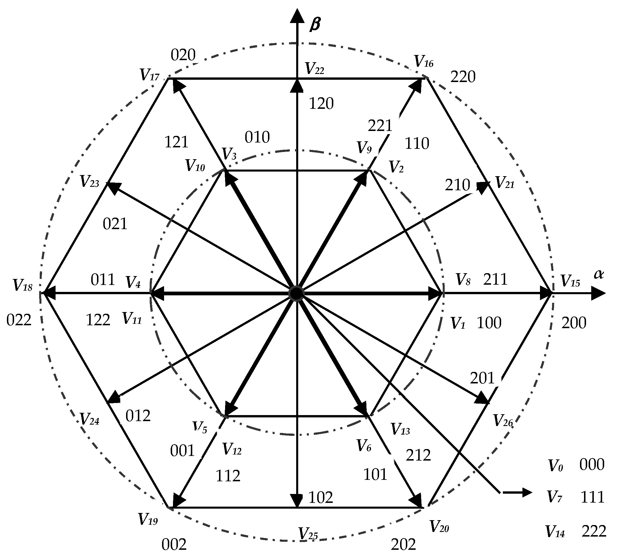
The transformation of voltages from the natural three phases into bi-phases (α-β) gives voltage vectors associated to the stator flux position. The vector’s various state number is 19 since some of the 27 possibilities yield the same voltage vector. The presentation of all voltage vectors of the three-level inverter in the bi-phasic frame is shown in Figure 2.
The space of the three-level inverter voltage vectors must be divided into 12 sectors instead of 6 using the diagonal between the long vector and the adjacent medium. The appropriate vector is chosen based on the torque and the flux errors from all 19 different available vectors, Figure 2.
The implementation of DTC to the studied system is accomplished by selecting the optimal vector and applying it to the three-level inverter. In order to establish the control with the proposed topology, first, the estimated values of torque and flux are compared with the references, and then the errors are digitized out of the hysteresis regulators, five-level and three-level comparators, respectively, which gives the variable flux (Cflx) and the variable torque (Ctrq). The number of sector N is determined using the α-β rotor flux component. If the torque comparator output is high or equal to two, the inverter state is considered high, otherwise the state is considered low. For the torque regulation, the use of a five-level hysteresis comparator permits the ability to have both rotation directions of the rotor flux compared to the stator flux. The output of this regulator is represented by a Boolean variable, Ctrq, indicating if the torque needs be raised (Ctrq = 2 or = 1), reduced (Ctrq = −2 or = −1), or kept constant (Ctrq = 0). For rotor flux control, a three-level hysteresis comparator could be used. Therefore, the rotor flux magnitude Φr is able to be controlled. The output of the flux regulator is also represented by a Boolean variable, Cflx, indicating if the flux needs be raised (Cflx = 1), reduced (Cflx = −1), or kept constant (Cflx = 0) to preserve it: |Φr_refΦr| ≤ Φr.
The switching table of the three-level inverter DTC is presented in Table 1. This table is considered to select the appropriate vector using the information described above (numerical errors of flux Cflx and torque Ctrq, and the number of sector N). When the impact of each voltage vector is analyzed, it may be observed that the vector impacts the torque and flux with the modulus and vector direction changes. The null voltage vectors (V0, V7, and V14) are selected alternately, in order to minimize the number of switches in the inverter arms [23].

3.2. The Proposed Fuzzy PID Design and Local Reactive Power Compensation Description

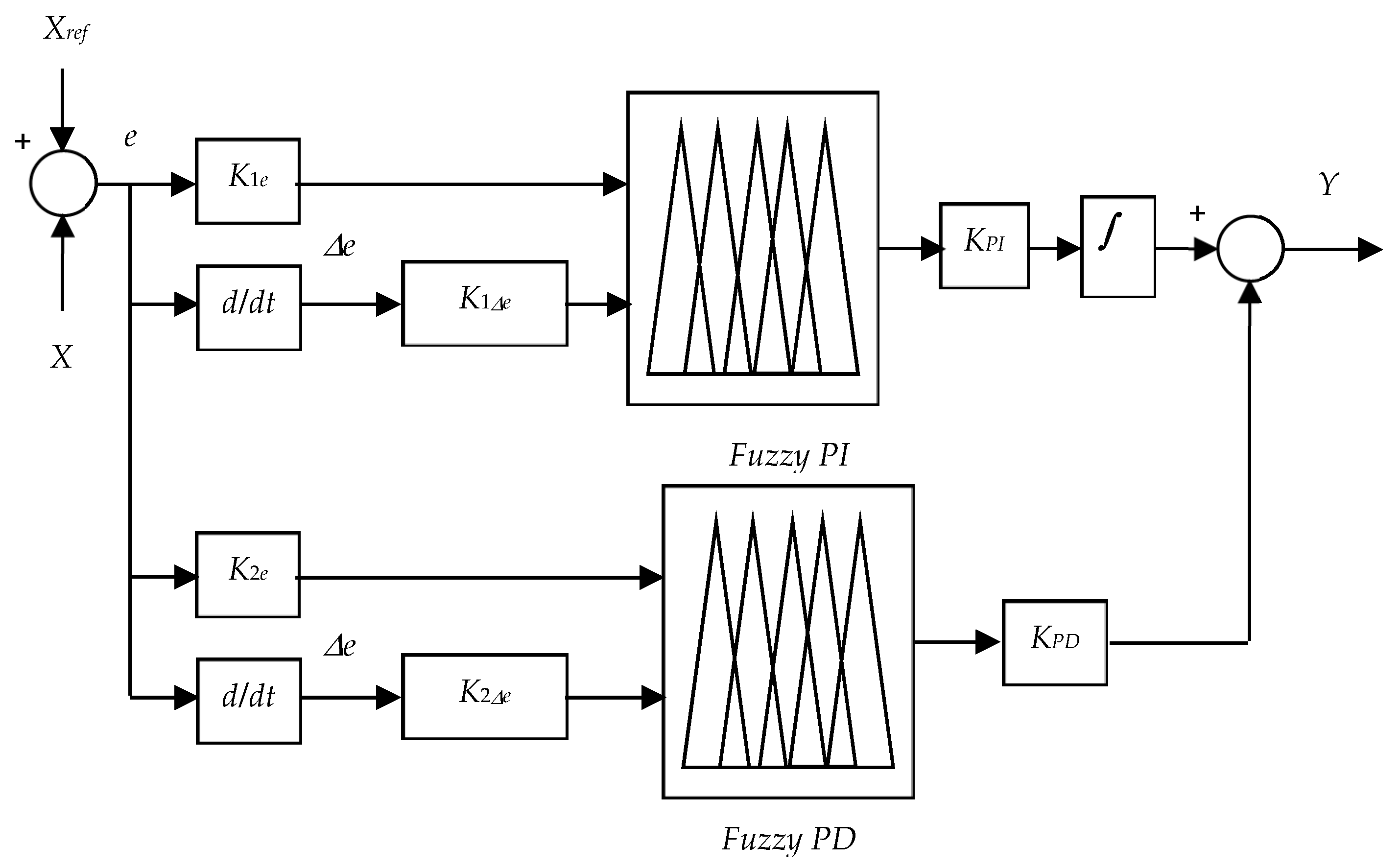
The PID controller is designed using the fuzzy logic controller (FLC) based on Mamdani inference. There are two FLCs; the first is utilized for the generation of electromagnetic torque reference in the speed loop. The second is for the reactive power loop to create the rotor flux reference. Figure 3 shows the proposed fuzzy PID (F-PID) diagram.
In the first loop (the speed loop): X represents the DFIG mechanical speed (Ω) and Xref represents its reference (Ωref), while the output of this loop (Y) will be the electromagnetic torque reference (Tem-ref). In the second loop (the reactive power loop): X represents the estimated reactive power (QAC) and Xref represents its reference (QAC-ref) (it is the demand in reactive power of the AC grid), the output of this loop (Y) is the reference of the rotor flux (Φr-ref).
K1e, K1Δe, and KPI are scaling factors of the fuzzy PI, and K2e, K2Δe, and KPD are scaling factors of the fuzzy PD. e and Δe are the error and its derivative, respectively.
It is well known that fixed gains are very sensitive when the system is exposed to parameter uncertainties and external disturbances. Thus, to overcome this problem and to compute an optimal controller, a fuzzy controller is introduced as a supervisor to compute the damping gains of the PI and PD controllers that are considered the outputs of the fuzzy supervisor to overcome the problem caused by parameter uncertainties which makes the proposed strategy intelligent. The selected fuzzy control design process consists of: fuzzification of the inputs, formulation of the rules, and finally defuzzification of the output. Triangular and trapezoidal types symmetrically and uniformly distributed are used to select the membership functions. The proposed F-PID is built using two different FLCs, the first is fuzzy PI (F-PI) and the other is fuzzy PD (F-PD). Figure 4 presents the fuzzification membership functions (MFs) of inputs and outputs of both FLCs. Moreover, the fuzzy rules are presented in Table 2 for the first regulator F-PI and Table 3 for the second regulator F-PD. Finally, the method of center of gravity (CoG) is invested for the defuzzification of both FLCs as its the most commonly used defuzzification method, also commonly referred to as the centroid method. This method determines the center of area of a fuzzy set and returns the corresponding crisp value [2,19].
The control of the DC/AC converter (II) imposes at the output a unit power factor with a constant frequency at 50 Hz, while the reactive power is provided by the DFIG.
{ Q A C = Q s + Q r A C { Q A C = Q g + Q L A C Q L A C = P L A C · t g ( ϕ L A C )
where Qs depicts the DFIG’s stator reactive power, QL-AC depicts the reactive powers exchanged with the AC load, QAC depicts AC grid reactive power, Qrg depicts the reactive power transferred via the second converter (II) (DC/AC), and ϕL-AC depicts the local load phase.

4. Simulation Results

The proposed topology (DPRC-3N) is tested and compared to another topology using a two-level inverter (DPRC-2N) using Matlab/Simulink software. The Matlab/Simulink model scheme of the studied system is presented in Appendix A. The system parameters can be found in [1]. This study is subdivided into four parts, which are:
(1)
Robustness and tracking tests of references for random profiles of the setpoints:
In this case, the objective is to analyze the performances of the proposed topology from the point of view of robustness and tracking to the sudden and random variations in references. This will be done while going through all the operating modes of the DFIG in a random and continuous way; as a generator of active power, according to the profile of the wind speed, passing from the sub-synchronous mode to the synchronous and super-synchronous modes until the overspeed. Then as a local compensator of the reactive power. This reflects a behavior close to the real operation of a power plant. In this part two topologies are treated, while comparing the one proposed in this work to another one based on a two-level inverter.
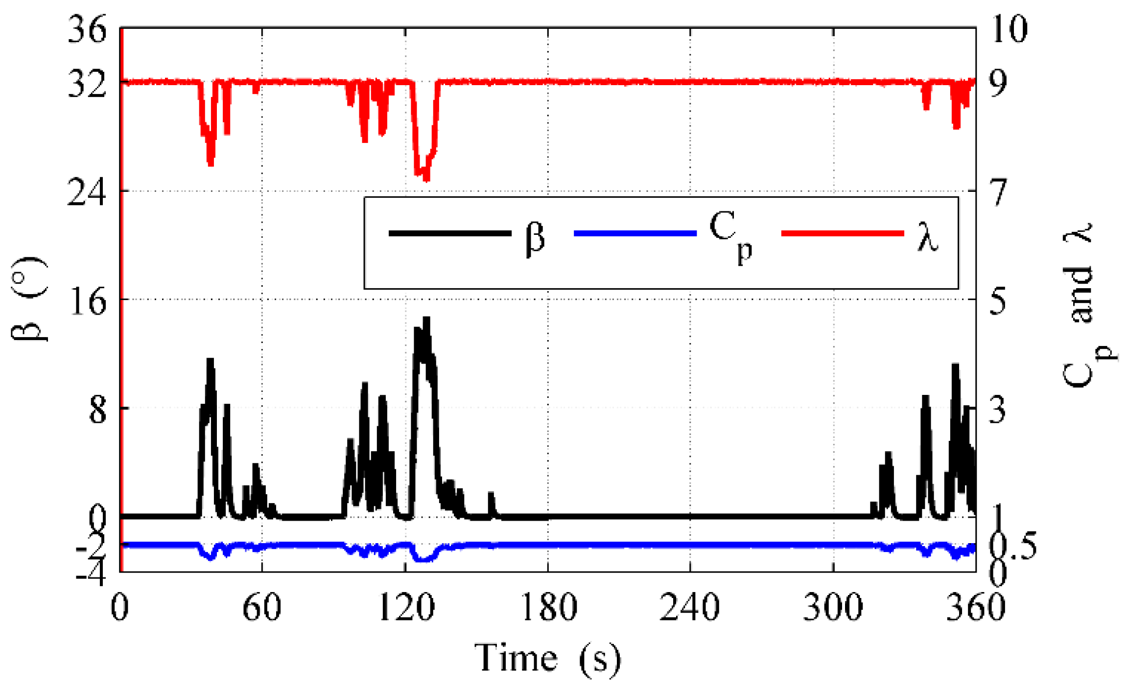
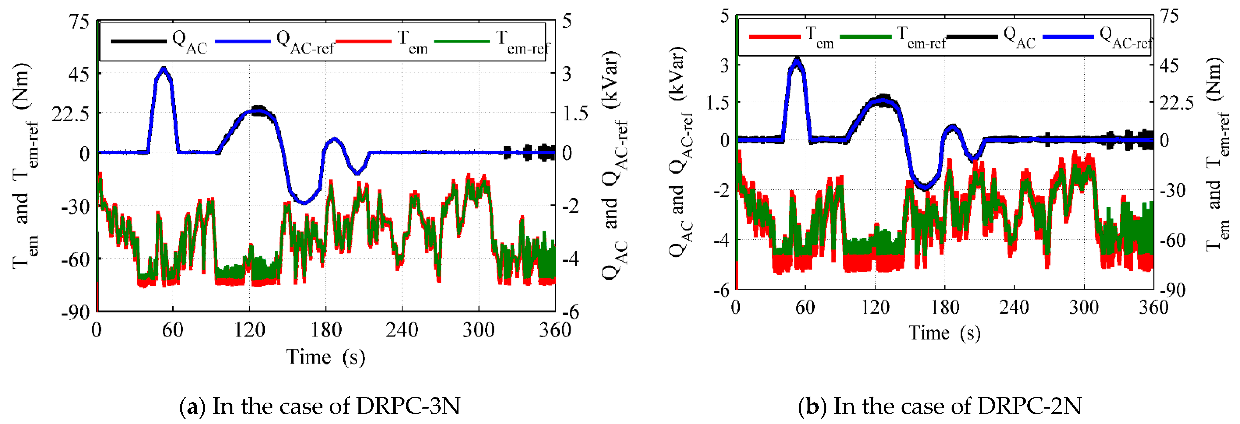
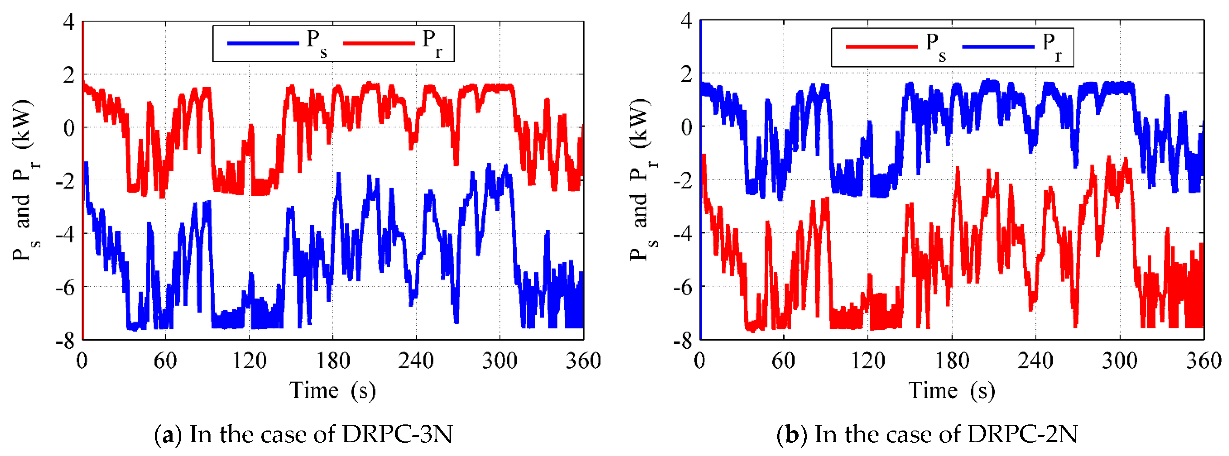
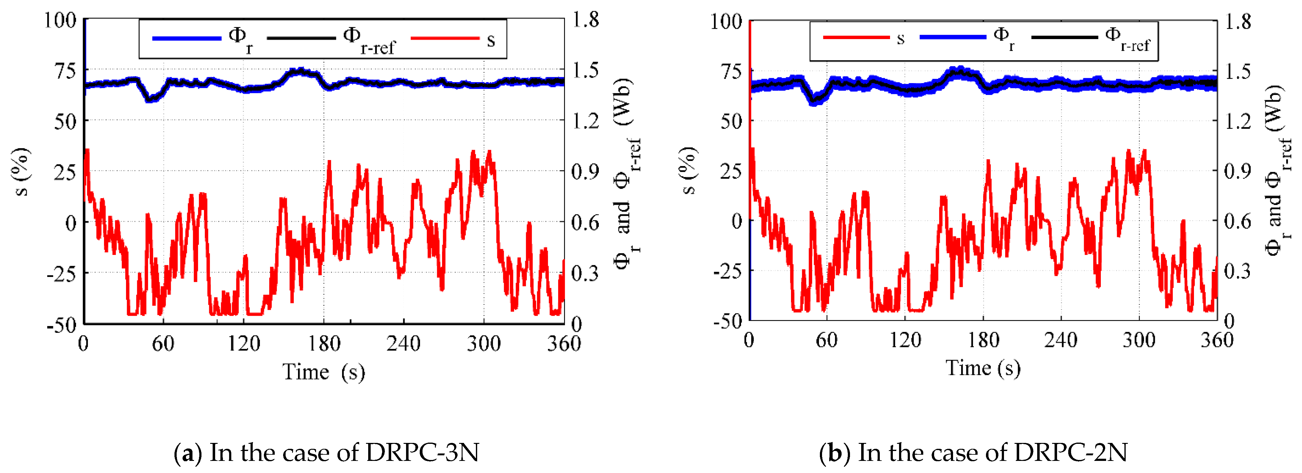
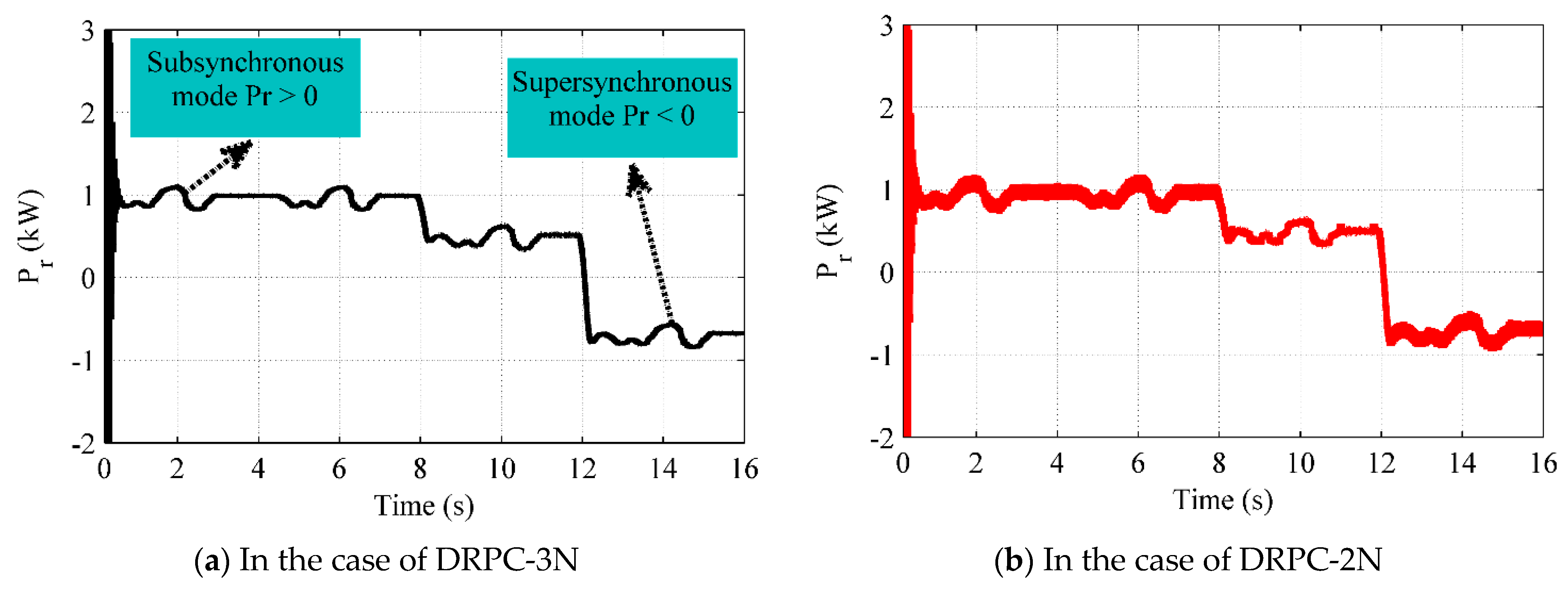
The total hourly averages of the wind speed data, up to 360 s (6 min), and the DFIG mechanical speed profiles are presented in Figure 5. Figure 6 illustrates the β, λ, and Cp. When the power reached its maximum value, the pitch angle control was activated. Therefore, the DFIG speed is maintained at its maximum amount. Then, the electromagnetic torque is maintained constant, but the reactive power followed the AC grid demand for both topologies, as presented in Figure 7. However, in regions I and II, the generated active power is maximized by the MPPT algorithm, as presented in Figure 8. This figure shows that all the powers transferred between the WT-DFIG system and the AC grid for both topologies, respectively. The rotor power (Pr) switches its direction, marked by its sign, according to the generator slip; this reflects two operating modes, sub- and super-synchronous, through the synchronous mode, as presented in Figure 9a–c.
The control performance can be analyzed in the reference’s pursuit of the DFIG mechanical speed, the electromagnetic torque, the reactive power, and the rotor flux as illustrated respectively in Figure 7 and Figure 10. The Ωmec and Tem vary according to the wind speed profile to maximize the generated active power in zones I and II of the WT characteristic. Meanwhile, in zone III, both Ωmec and Tem are kept constant to limit the produced power. Therefore, the rotor flux magnitude is maintained at its reference and changes depending on the involved reactive power compensation, as shown in Figure 10.
The WT-DFIG operates in the optimal way where the possibility of using the DFIG to control and manage the active–reactive powers is confirmed. Hence, these results affirm the good performances and the robustness of the proposed DRPC control. In addition, it can be clearly noticed that the torque ripples are decreased by about 65% compared to the results given in references [1,18,19].
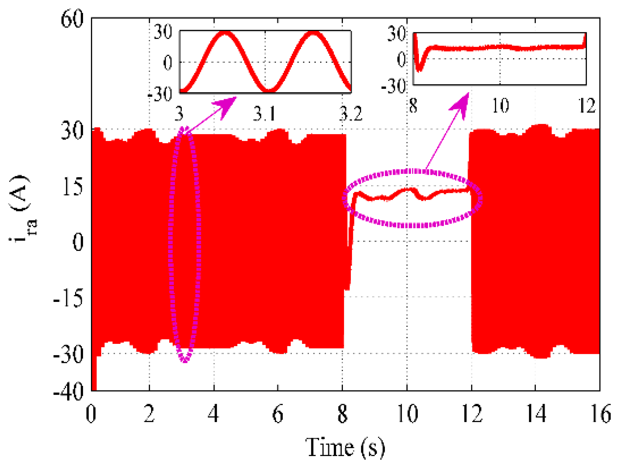
The two axes rotor flux waveforms (Φ and Φ) are presented Figure 11a–c, with a sinusoidal behavior during sub- and super-synchronous modes. Nevertheless, both rotor flux components (Φ and Φ) have a continuous behavior during the synchronous mode. Additionally, the rotor phase currents have a direct waveform during this particular mode, as shown in Figure 12c. The sinusoidal behavior of the rotor phase currents can be noticed during the other modes: sub- and super-synchronous as shown in Figure 12a,b. The random evolution of the rotor current magnitude is related to the electromagnetic torque variations and its pulsation is dependent on the slip variations.
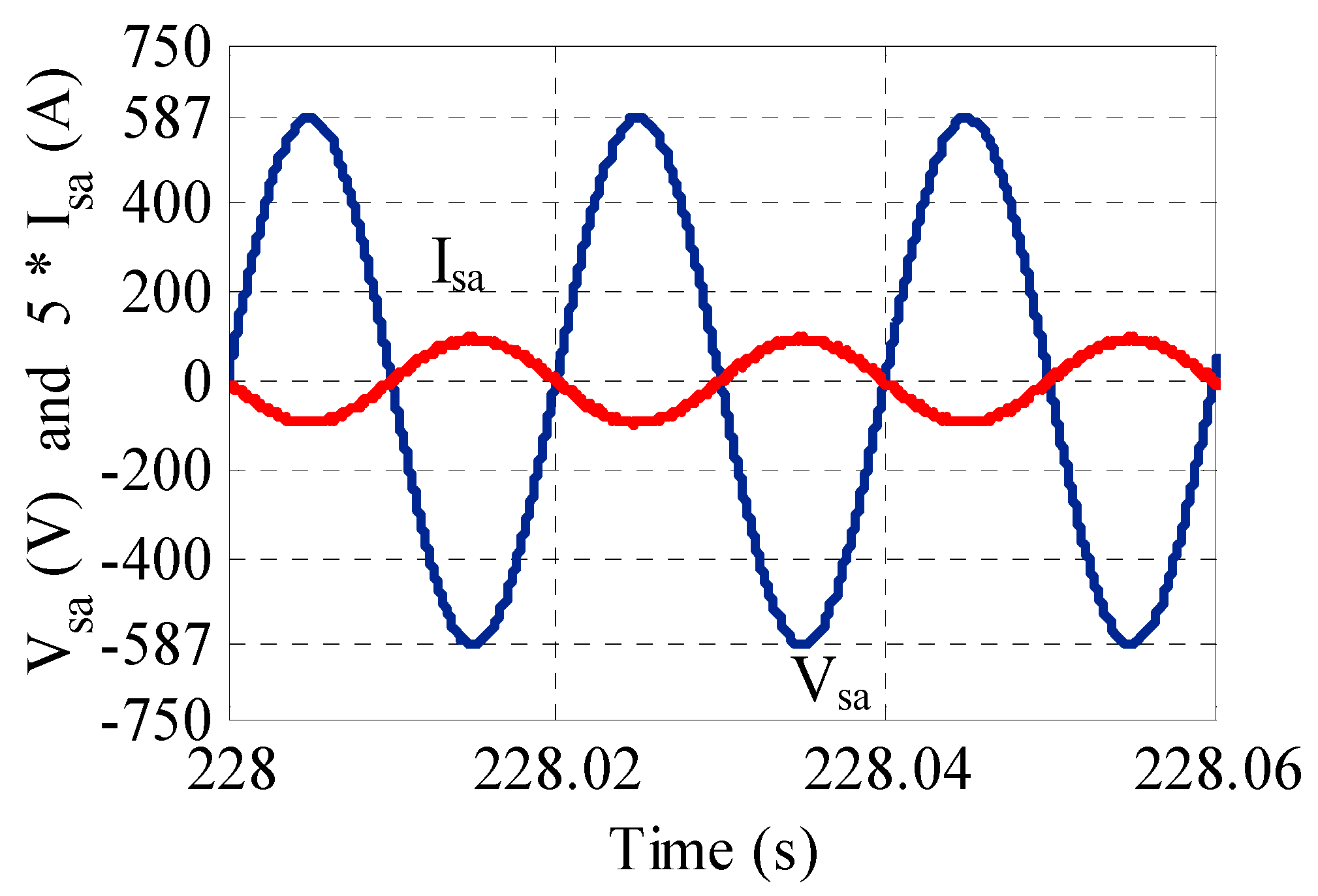
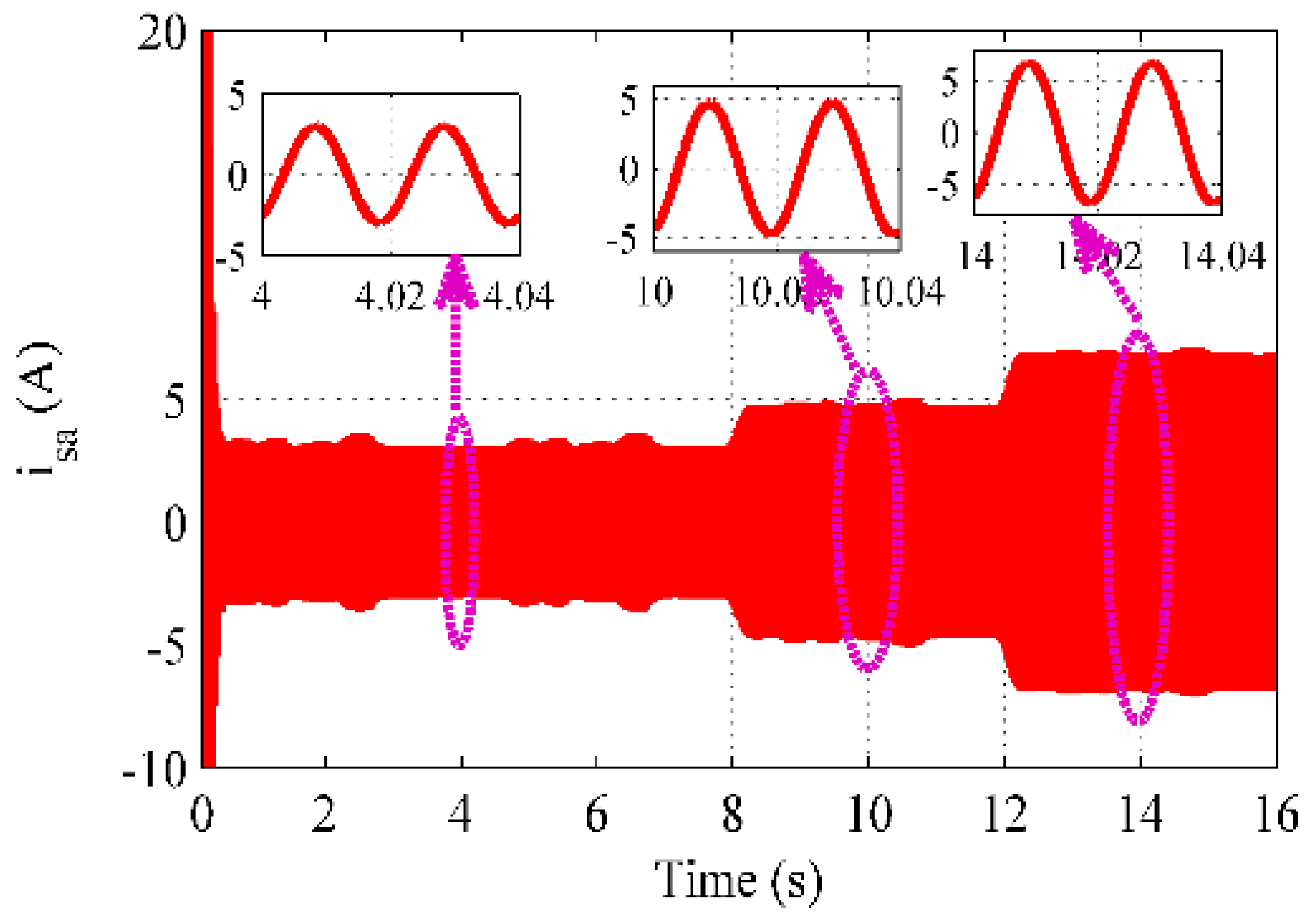
The generated AC grid current keeps a sinusoidal of a constant frequency (50Hz) form throughout all operating modes, along with a variable amplitude, as shown in Figure 13, Figure 14 and Figure 15.
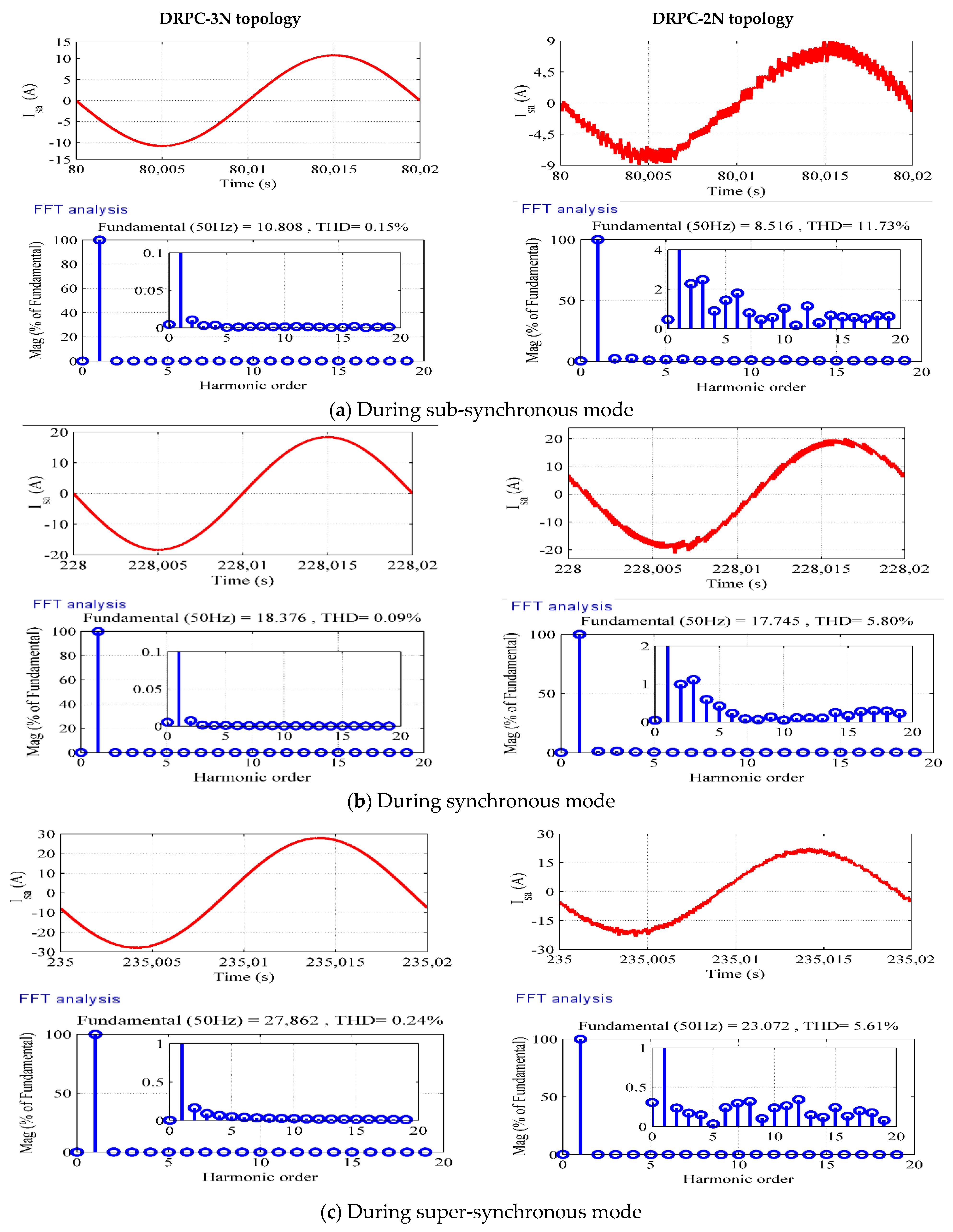
The proposed control-enhanced DRPC applied to a DFIG three-level inverter, the waveforms of the generated currents supplying the AC grid, are significantly improved compared to that of the two-level inverter, as studied in [1,19], with a low THD, as illustrated in Figure 16a–c. Furthermore, there was an almost constant frequency of 50 Hz. This indicates the improved energy quality produced to supply the AC grid.
(2)
Tests of reference tracking for profiles in steps of the setpoints:
The objective in this part is to analyze the performances of reference tracking of the proposed topology (DPRC-3N), compared to DRPC-2N. The choice of the two profiles, wind speed and reactive power to be compensated locally, is based on:
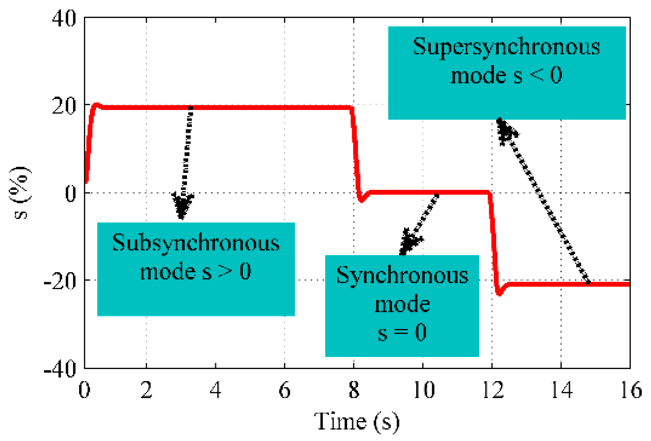
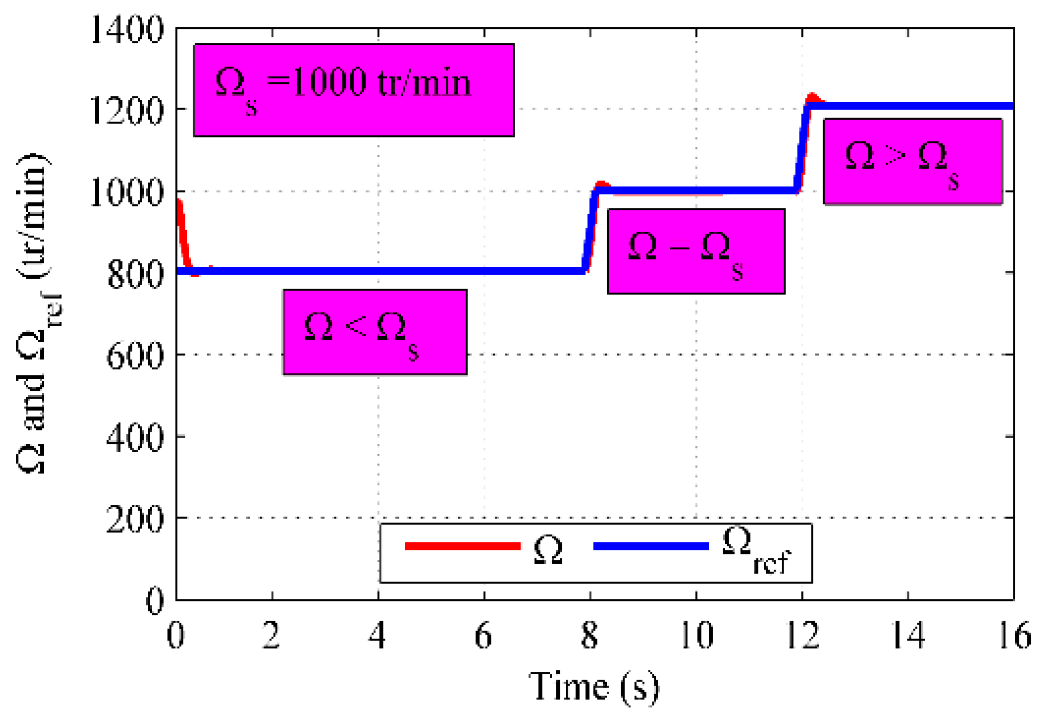
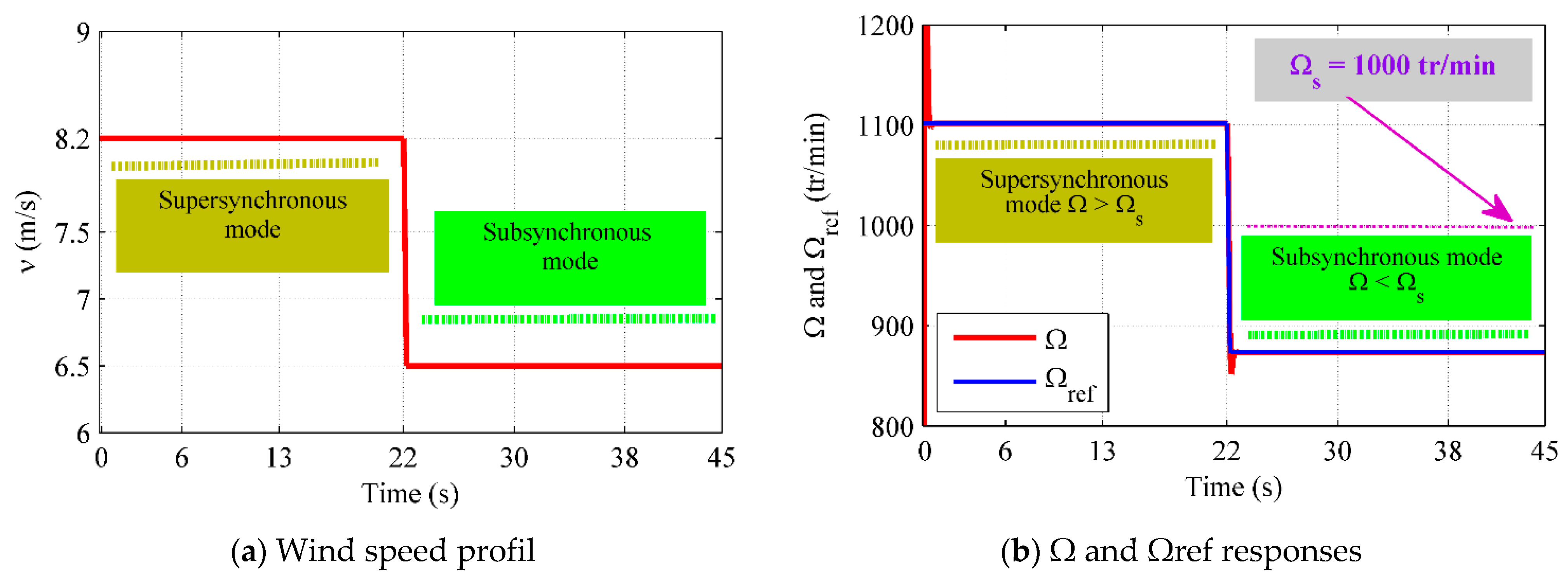
  • Going through all DFIG operating modes in a consecutive and continuous manner, starting from the sub-synchronous mode to the synchronous and then the super-synchronous mode, as illustrated in Figure 17, Figure 18 and Figure 19.
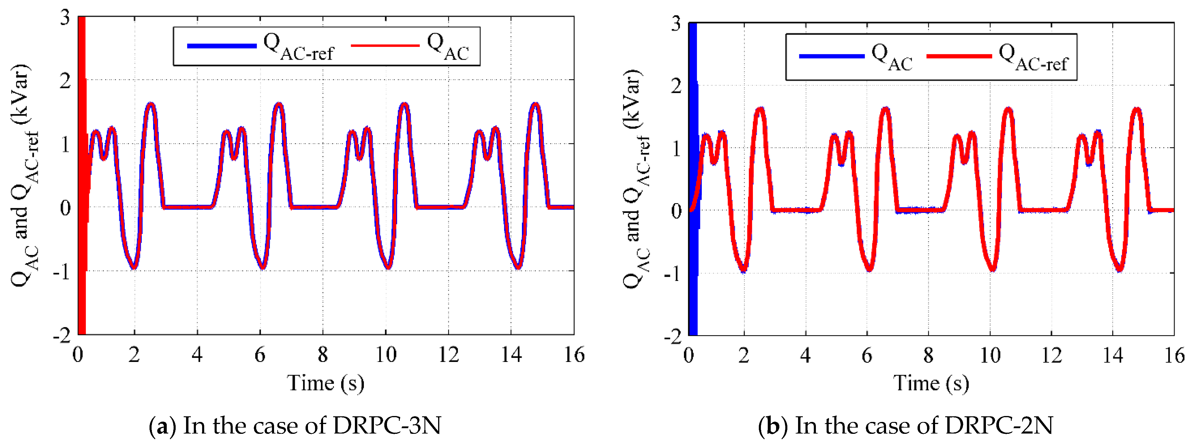
  • Ensuring full operation of a local reactive power compensator. By switching from operating in unit power factor mode (QAC = 0 Var), then in excess reactive power consumption mode (QAC > 0 Var), to deficit reactive power generation mode in the grid connection bar set, as illustrated in Figure 20.
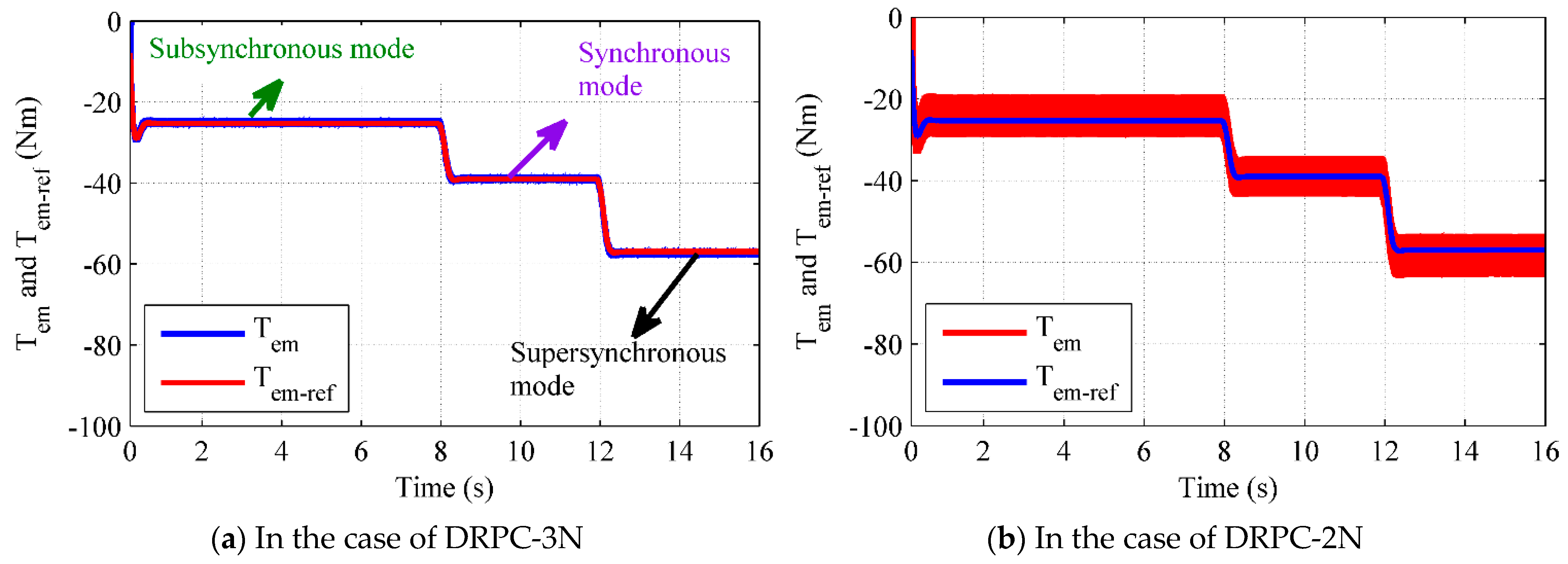
The references tracking is very remarkable on the obtained results, as illustrated in Figure 19, Figure 20, Figure 21 and Figure 22, respectively, the DFIG mechanical speed, the reactive power, the electromagnetic torque and the rotor flux, for both topologies (DPRC-3N and DPRC-2N). The DFIG speed and Tem vary with the wind speed profile to maximize the active power generated using the MPPT algorithm, as shown in Figure 23 and Figure 24. Therefore, the rotor flux amplitude is kept at its reference and varies according to the local compensation of the reactive power involved.
The waveforms of the rotor flux components in the α-β frame (Φ and Φ) with that of currents ira and ira, zoomed during all DFIG operation modes, confirm the results shown in Figure 11, Figure 12, Figure 13, Figure 14, Figure 15 and Figure 16, as presented in Figure 25, Figure 26 and Figure 27.
The proposed control-enhanced DRPC applied to a DFIG three-level inverter (DRPC-3N), the waveforms of the generated currents supplying the AC grid, are significantly improved compared to that of the two-level inverter (DRPC-2N), with a low THD, as illustrated in Figure 15 and Figure 16a–c. Additionally, there was an almost constant frequency of 50 Hz. This indicates the improved power quality produced to supply the AC grid.
(3)
Robustness tests against parametric variations:
In this part, the effect of temperature increase during the operation of the DFIG is taken into account. This causes an increase in the generator winding resistances (Rs and Rr). Then, the effect of saturation of the DFIG magnetic circuit on the behavior of the proposed DRPC-3N is analyzed. This saturation decreases the mutual self-inductance (M) between the DFIG stator and rotor, which causes the cyclic self-inductances of each winding to decrease (Ls and Lr).
This is made in two separate tests:
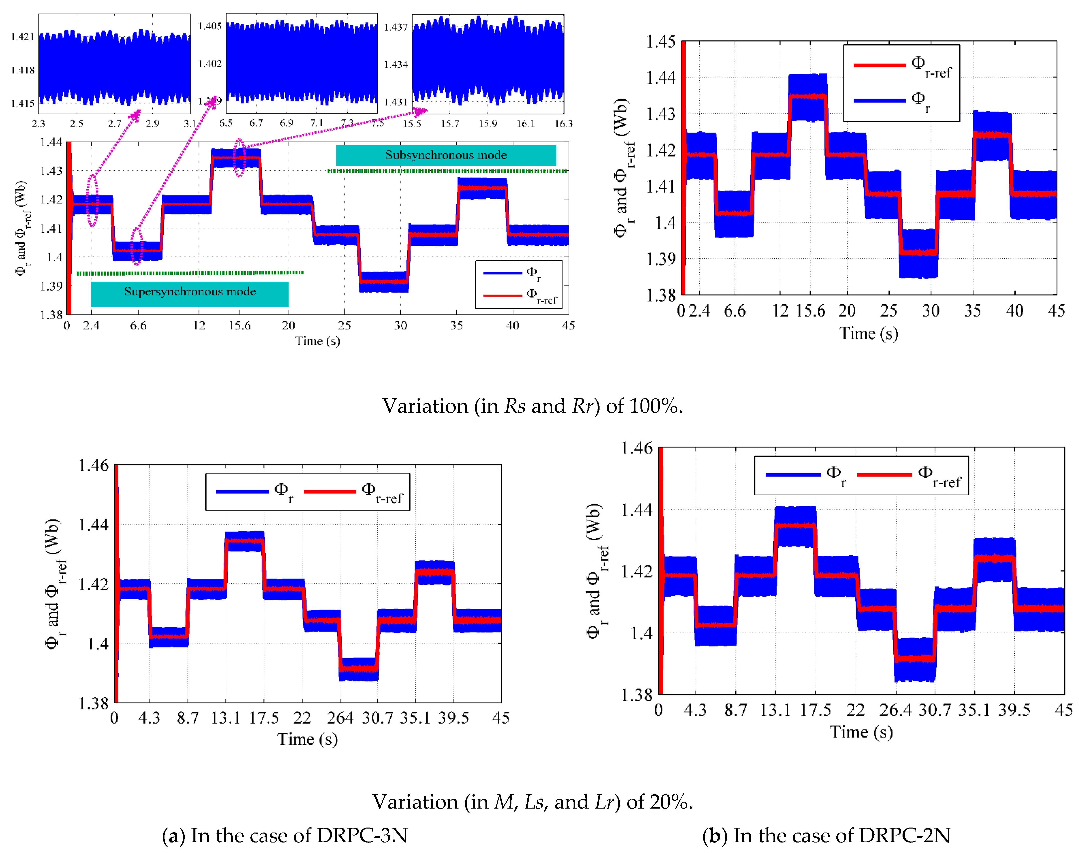
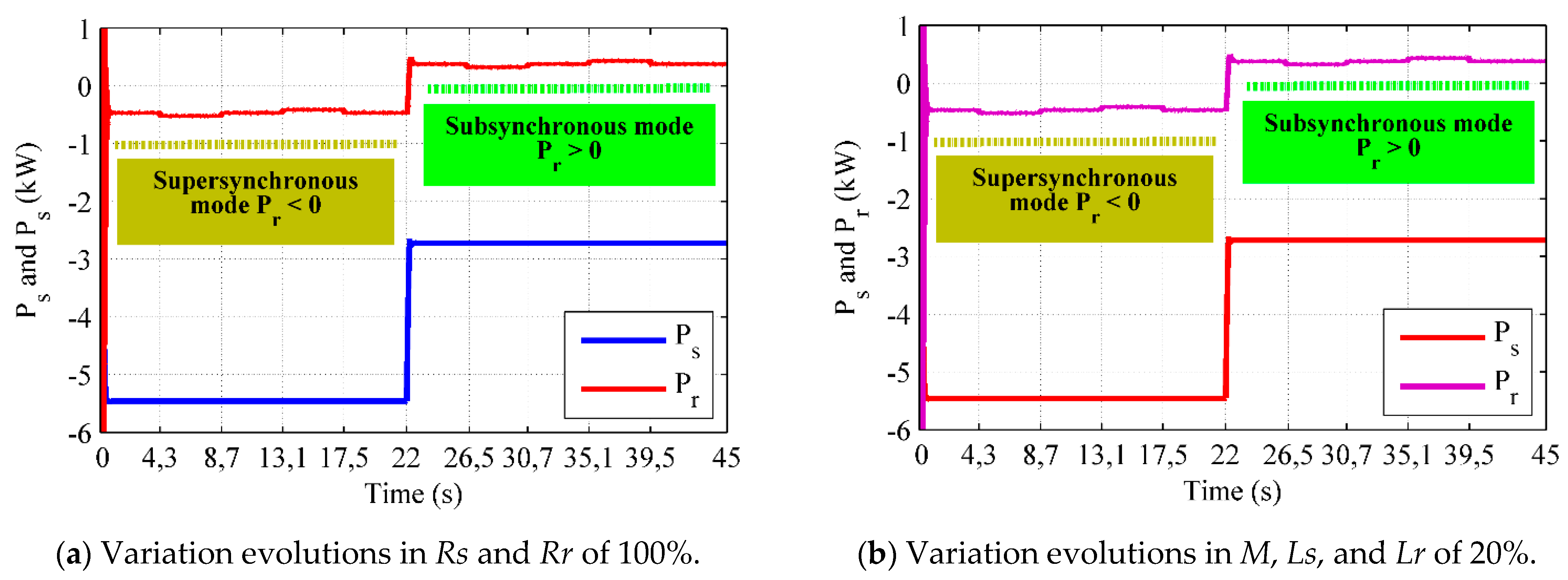
  • The first one is to assume that after the operation of the wind generator, the heating of the stator and rotor windings increases the resistances (Rs and Rr) by 100% of their nominal values, as presented in Figure 28a.
  • The second is to consider that the saturation of the magnetic circuit of the DFIG causes a decrease in the value of the natural mutual between the stator and rotor windings (M) of 20%. This action directly decreases the cyclic inductances values of each winding (Ls and Lr), as presented in Figure 28b.
Setpoint profiles have been selected in a way to test the different DFIG operating modes, while accommodating all speed modes (super-synchronous and sub-synchronous modes passing through the synchronous mode) as well as the three compensation regimes (QAC > 0, QAC < 0, and QAC = 0), as shown in Figure 29, Figure 30, Figure 31, Figure 32 and Figure 33.
From the results obtained for both topologies (DPRC-3N and DRPC-2N), it can be clearly seen that both techniques show a very good robustness with respect to the parametric variations, but the ripples band is always small in the case of the proposed DRPC-3N compared to DRPC-2N. Knowing that, the major handicap of DTC is the sensitivity to the resistance which intervenes in the estimation of the flux. In this case, the combination of DTC and fuzzy logic reinforces this robustness as shown in the different obtained results, as shown in Figure 30, Figure 31, Figure 32 and Figure 33, particularly Figure 32a. In this figure which represents the rotor flux, whatever the evolution of the rotor resistance (Rr), which intervenes in the estimation of this flux, the latter always remains insensitive to these variations. This confirms that the proposed DRPC, whether DRPC-2N or DRPC-3N, is very robust technique to machine parametric variations.
(4)
Summary of the obtained results with comparison:
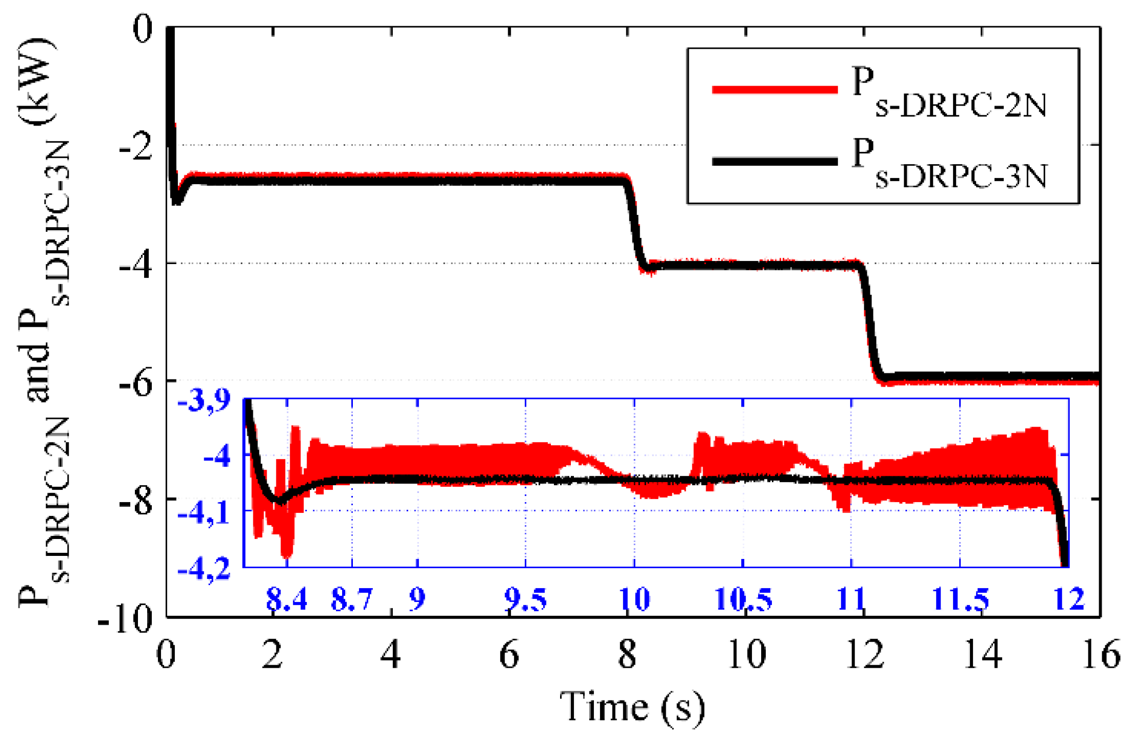
A comparative analysis between DRPC-2N and the improved DRPC (DRPC-3N) of ripples of: electromagnetic torque, rotor flux, and the generated and local reactive power compensation with the generated current THD and its frequency during different DFIG operation modes is summarized in Table 4 and Table 5. All ripples caused by both strategies are illustrated in Figure 34, Figure 35, Figure 36, Figure 37 and Figure 38.
As expected, their ripples are low in the case of DRPC-3N while they are important in the DRPC-2N topology. Indeed, the proposed DRPC-3N allows for the reduction of the ripples of the electromagnetic torque, generated active power, and the rotor flux magnitude by about 60.7%, 15.25%, and 30.3%, respectively. Furthermore, those of the compensation reactive power are minimized by about 20.1%.
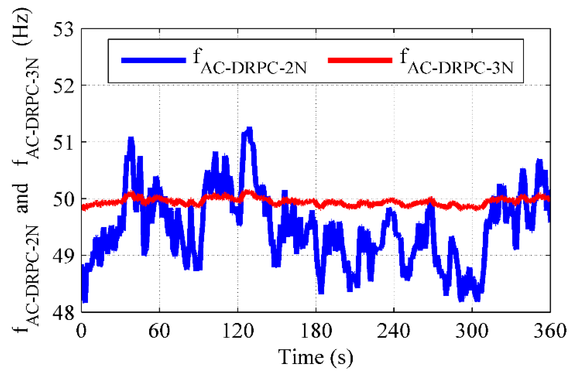
In addition, the ripple of the grid-supplied phase current frequency in both control strategies is illustrated in Figure 35, and the ripples of this frequency is summarized in Table 4. It can be noticed that, when using the DRPC-3N topology, the frequency is almost constant with a mean value of 50.00 Hz with an error of 1.50%, which is better than that obtained in the case of DRPC-2N. Therefore, the AC grid generated current frequency ripples reduction in DRPC-3N compared to DRPC-2N is about 50.80%.
Furthermore, with the proposed control topology (DRPC-3N), the waveforms supplying the AC grid are significantly improved compared to that of DRPC-2N with a total harmonic distortion (THD) largely below 1%, (above this value should be reported as mentioned by IEC standards) as presented in Figure 16a–c and Table 5. This confirms a better quality of generated power that supplied the AC grid. Moreover, the total losses decrease, leading to this approach having the best efficiency.
Moreover, to better power quality performance, the proposed DRPC-3N technique is very robust to parametric variations in the machine as well as to sudden and random variations in reference quantity profiles.

5. Conclusions

The performances and robustness of DRPC have been presented in this paper. This technique is applied a three-level inverter to control the active and reactive powers of DFIG. Most benefits of this generator are linked with the power converter, those being: a management system of active energy and a reactive power local compensator. In addition, the quality and performances of the proposed method are tested in a way to reproduce certain restrictions that reflect the actual wind operation. Thus, the random behavior of the wind speed allowed the utilization of the machine in its different operation modes. Attention is focused on the dynamic performance of DRPC. In addition, to highlight the proposed technique (DRPC-3N), a comparative study with DRPC-2N is presented. Robustness tests against parametric variations of the machine, taking into account the effect of the heating of the windings as well as the saturation of the magnetic circuit, were performed. This is in addition to the tests for the sudden and random variations in the profiles of reference quantities. The effectiveness and performance of the proposed scheme control is demonstrated by simulation tests under Matlab/Simulink.
The obtained results clearly show the good performances of the proposed system control in the different operation modes, in terms of pursuit of the references or the robustness. Thus, the significant performances of the DFIG remain under wind randomness variations. This allows us to confirm the robustness behavior and the satisfactory performances of the proposed technique. Additionally, they justify the utility of the DFIG in the possibility of management and control of the reactive and active powers. This leads to the use of the DFIG as a reactive power local compensator.
The simulation results show that the application of the proposed control technique significantly enhances conversion system performance, which amounts to minimizing the current’s THD and the torque oscillations. These results indicate that the combination of the advantages of DTC combined with the FLC gives a better answer to the requirements of the grid.
The overall control, based on DRPC-3N, has significantly improved the performances of the overall system under wind randomness variation. This allows for the confirmation of the robustness behavior and the satisfactory performances of the proposed control. In addition to the contribution of this control technique, the three-level inverter used in the system has also participated in improving the power quality injected into the AC grid.

Author Contributions

Conceptualization, Y.B. and Y.S.; methodology, Y.B.; software, Y.S. and M.S.C.; validation, Y.B., N.U. and M.S.C.; formal analysis, N.U.; investigation, M.B.; resources, Y.B.; data curation, Y.S.; writing—original draft preparation, Y.B. and K.T.; writing—review and editing, N.U., T.T. and Y.B.; visualization, Y.B.; supervision, S.T.; project administration, S.T.; funding acquisition, N.U. and K.T. All authors have read and agreed to the published version of the manuscript.

Funding

This work was supported by Taif University Researchers Supporting Project number (TURSP-2020/144), Taif University, Taif, Saudi Arabia. This research was also supported by grant 235 number ENV6402012N from Prince of Songkla University.

Data Availability Statement

Not applicable.

Acknowledgments

The authors acknowledge the funding support provided by Taif University Researchers Supporting Project number (TURSP-2020/144), Taif University, Taif, Saudi Arabia. This research was also supported by grant 235 number ENV6402012N from Prince of Songkla University.

Conflicts of Interest

The authors declare no conflict of interest.

Appendix A

Figure A1. The Matlab/Simulink Model Scheme of the Studied System.
Sustainability 13 09060 g0a1

References

  1. Tamalouzt, S.; Benyahia, N.; Rekioua, T.; Abdessemed, R. Performances analysis of WT-DFIG with PV and fuel cell hybrid power sources system associated with hydrogen storage hybrid energy system. Int. J. Hydrogen Energy 2016, 41, 21006–21021. [Google Scholar] [CrossRef]
  2. Shihabudheen, K.V.; Pillai, G.N.; Raju, S.K. Neuro-Fuzzy Control of DFIG Wind Energy System with Distribution Network. Electr. Power Compon. Syst. 2018, 46, 1416–1431. [Google Scholar] [CrossRef]
  3. Jaladi, K.K.; Sandh, K.S. Real-time simulator based hybrid controller of DFIG-WES during grid faults design and analysis. Electr. Power Energy Syst. 2020, 116, 105545. [Google Scholar] [CrossRef]
  4. Kerrouche, K.D.E.; Mezouar, A.; Belgacem, K. Decoupled Control of Doubly Fed Induction Generator by Vector Control for Wind Energy Conversion System. Energy Procedia 2013, 42, 239–248. [Google Scholar] [CrossRef] [Green Version]
  5. Adjoudj, M.; Abid, M.; Aissaoui, A.; Ramdani, Y.; Bounoua, H. Sliding mode control of a doubly fed induction generator for wind turbines. Rev. Roum. Sci. Techn. Electrotechn. Energ. 2011, 56, 15–24. [Google Scholar]
  6. Abdelfatteh, A.; Abid, M. Hybrid fuzzy sliding mode control of a doubly fed induction generator in wind turbines. Rev. Roum. Sci. Techn. Electrotechn. Energ. 2012, 57, 15–24. [Google Scholar]
  7. Hicham, S.; Benattous, D. Sensorless Optimal Power Control of Doubly Fed Induction Wind Generator Based on Extended Kalman Filter. Electroteh. Electron. Autom. 2017, 65, 34–41. [Google Scholar]
  8. Belabbas, B.; Allaoui, T.; Tadjine, M.; Denai, M. High Order Sliding Mode Controller Simulation by a Wind Turbine for DFIG Protection against Overcurrent. Electroteh. Electron. Autom. 2017, 65, 142–147. [Google Scholar]
  9. Fihakhir, A.M.; Bouhamida, M. Nonlinear Control of a Doubly Fed Induction Generator Driven Wind Turbine. Electroteh. Electron. Autom. 2016, 64, 23–32. [Google Scholar]
  10. Hu, J.; Yuan, X. VSC-based direct torque and reactive power control of doubly fed induction generator. Renew. Energy 2012, 40, 13–23. [Google Scholar] [CrossRef]
  11. Yaichi, I.; Semmah, A.; Wira, P.; Djeriri, Y. Super-twisting Sliding Mode Control of a Doubly-fed Induction Generator Based on the SVM Strategy. Period. Polytech. Electr. Eng. Comput. Sci. 2019, 63, 178–190. [Google Scholar] [CrossRef]
  12. Kassem, A.M.; Hasaneen, K.M.; Yousef, A.M. Dynamic modeling and robust power control of DFIG driven by wind turbine at infinite grid. Int. J. Electr. Power Energy Syst. 2013, 44, 375–382. [Google Scholar] [CrossRef]
  13. Taib, N.; Metidji, B.; Rekioua, T. A Fixed Switching Frequency Direct Torque Control Strategy for Induction Motor Drives Using Indirect Matrix Converter. Arab. J. Sci. Eng. 2014, 39, 2001–2011. [Google Scholar] [CrossRef]
  14. Arbi, J.; Ghorbal, M.J.-B.; Slama-Belkhodja, I.; Charaabi, L. Direct Virtual Torque Control for Doubly Fed Induction Generator Grid Connection. IEEE Trans. Ind. Electron. 2009, 56, 4163–4173. [Google Scholar] [CrossRef]
  15. Ben Alaya, J.; Khedher, A.; Mimouni, M.F. Speed-sensorless DFIG wind drive based on DTC using sliding mode rotor flux observer. Int. J. of Renew. Energ. Res. 2012, 2, 735–745. [Google Scholar]
  16. Payam, A.F.; Hashemnia, M.N.; Fai, J. Robust DTC Control of Doubly-Fed Induction Machines Based on Input-Output Feedback Linearization Using Recurrent Neural Networks. J. Power Electron. 2011, 11, 719–725. [Google Scholar] [CrossRef] [Green Version]
  17. Prasad, R.M.; Mulla, M.A. Mathematical Modeling and Position-Sensorless Algorithm for Stator-Side Field-Oriented Control of Rotor-Tied DFIG in Rotor Flux Reference Frame. IEEE Trans. Energy Convers. 2020, 35, 631–639. [Google Scholar] [CrossRef]
  18. Tamalouzt, S.; Idjdarene, K.; Rekioua, T.; Abdessemed, R. Direct Torque Control of Wind Turbine Driven Doubly Fed Induction Generator. Rev. Roum. Sci. Tech. Electrotech. Energ. 2016, 61, 244–249. [Google Scholar]
  19. Tamalouzt, S.; Rekioua, T.; Abdessemed, R. Direct torque and reactive power control of Grid Connected Doubly Fed Induction Generator for the wind energy conversion. In Proceedings of the 2014 International Conference on Electrical Sciences and Technologies in Maghreb (CISTEM), Tunis, Tunisia, 3–6 November 2014; pp. 1–7. [Google Scholar]
  20. Suganthi, L.; Iniyan, S.; Samuel, A.A. Applications of fuzzy logic in renewable energy systems—A review. Renew. Sustain. Energy Rev. 2015, 48, 585–607. [Google Scholar] [CrossRef]
  21. Louarem, S.; Belkhiat, S.; Belkhiat, D.E.C. A control method using PI/fuzzy controllers based DFIG in wind energy conversion system. In Proceedings of the 2013 IEEE Grenoble Conference, Grenoble, France, 16–20 June 2013; pp. 1–6. [Google Scholar]
  22. Meddouri, S.; Idjdarene, K.; Ferrarini, L. Control of Autonomous Saturated Induction Generator Associated to a Flywheel Energy Storage System. Rev. Roum. Sci. Tech. Electrotech. Energ. 2016, 61, 372–377. [Google Scholar]
  23. Nami, A.; Liang, J.; Dijkhuizen, F.; Demetriades, G.D. Modular Multilevel Converters for HVDC Applications: Review on Converter Cells and Functionalities. IEEE Trans. Power Electron. 2015, 30, 18–36. [Google Scholar] [CrossRef]
  24. Nami, A.; Zare, F. Multilevel Converters in Renewable Energy Systems; Renewable Energy; Hammons, T.J., Ed.; IntechOpen: Rijeka, Croatia, 2009. [Google Scholar] [CrossRef] [Green Version]
  25. Lega, A. Multilevel Converters: Dual Two-Level Inverter Scheme. Ph.D. Thesis, Electrical Engineering, University of Bologna, Bologna, Italy, 2007; pp. 39–51. [Google Scholar]
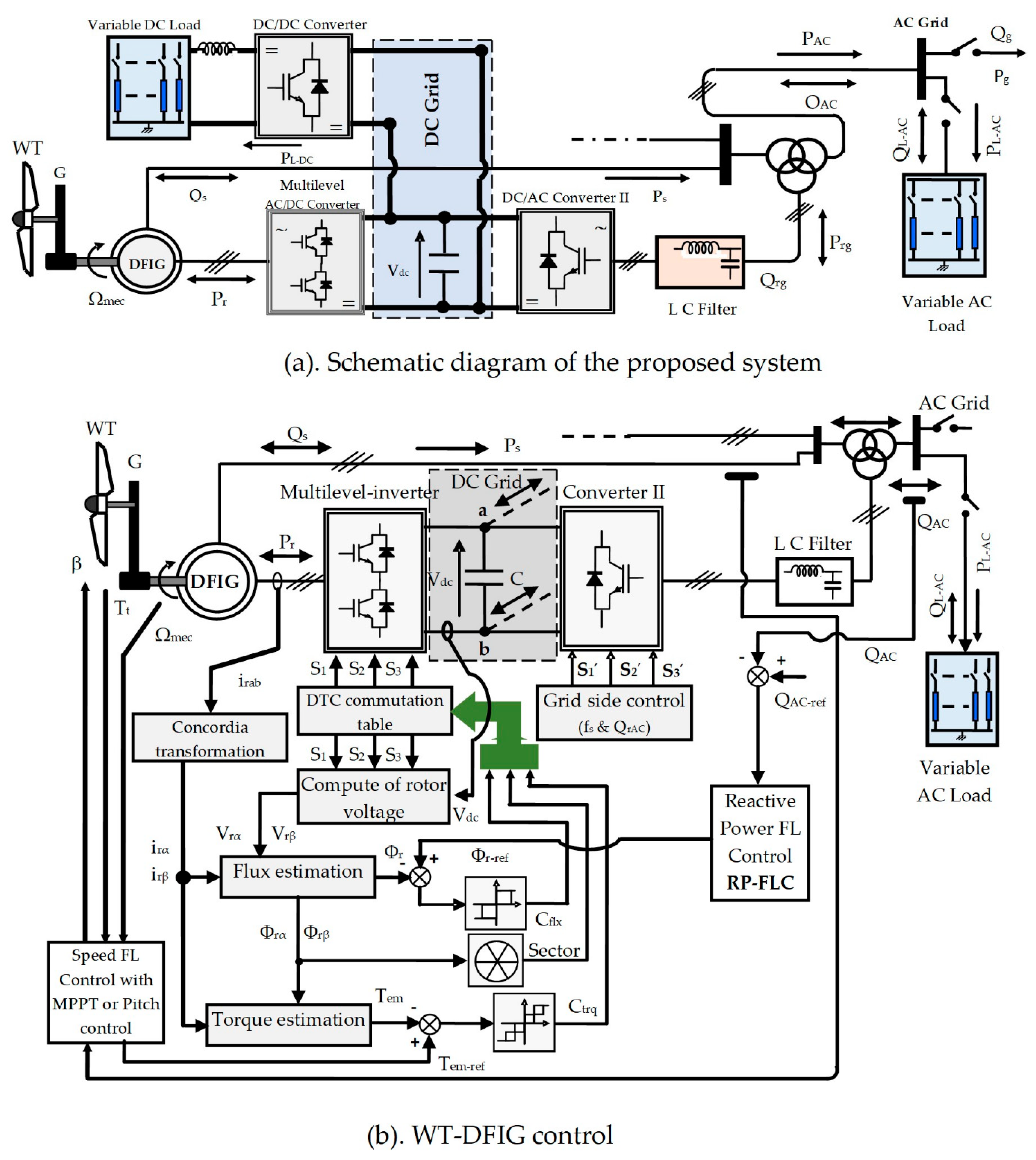
Figure 1. Global control scheme.
Sustainability 13 09060 g001
Figure 2. Scheme of three-level inverter voltage vectors.
Sustainability 13 09060 g002
Figure 3. Scheme of the proposed fuzzy PID for the two loops: speed and reactive power loops.
Sustainability 13 09060 g003
Figure 4. MFs of F-PID’s inputs and outputs.
Sustainability 13 09060 g004
Figure 5. Ω, Ωref, and υ responses for both treated topologies (DRPC-3N and DRPC-2N).
Sustainability 13 09060 g005
Figure 6. β, λ, and Cp responses for both treated topologies (DRPC-3N and DRPC-2N).
Sustainability 13 09060 g006
Figure 7. QAC, QAC-ref, Tem, and Tem-ref responses.
Sustainability 13 09060 g007
Figure 8. Pr and Ps responses.
Sustainability 13 09060 g008
Figure 9. The s response for both treated topologies (DRPC-3N and DRPC-2N).
Sustainability 13 09060 g009
Figure 10. Φr, Φr-ref, and s responses.
Sustainability 13 09060 g010
Figure 11. Φ and Φ responses for DRPC-3N topology.
Sustainability 13 09060 g011
Figure 12. Ira response for DRPC-3N topology.
Sustainability 13 09060 g012
Figure 13. Vsa and Isa responses for DRPC-3N topology.
Sustainability 13 09060 g013
Figure 14. Zoom of Vsa and Isa during the synchronous mode for DRPC-3N topology.
Sustainability 13 09060 g014
Figure 15. Zoom of the frequency current supplied to the AC grid and its reference.
Sustainability 13 09060 g015
Figure 16. Waveforms of the generated phase current (stator current) and its harmonic spectrum for both treated topologies, DRPC-3N and DRPC-2N.
Sustainability 13 09060 g016
Figure 17. Wind speed profile for both treated topologies (DRPC-3N and DRPC-2N).
Sustainability 13 09060 g017
Figure 18. The s responses for both treated topologies (DRPC-3N and DRPC-2N).
Sustainability 13 09060 g018
Figure 19. Ω and Ωref responses for both treated topologies (DRPC-3N and DRPC-2N).
Sustainability 13 09060 g019
Figure 20. QAC and QAC-ref responses.
Sustainability 13 09060 g020
Figure 21. Tem and Tem-ref responses.
Sustainability 13 09060 g021
Figure 22. Φr and Φr-ref responses.
Sustainability 13 09060 g022
Figure 23. Generated active power responses.
Sustainability 13 09060 g023
Figure 24. Rotor active power responses.
Sustainability 13 09060 g024
Figure 25. Φrα and Φrβ responses, with zooms during different operating modes, for DRPC-3N.
Sustainability 13 09060 g025
Figure 26. Ira response, with zooms during different operating modes, for DRPC-3N.
Sustainability 13 09060 g026
Figure 27. Isa response, with zooms during different operating modes, for DRPC-3N.
Sustainability 13 09060 g027
Figure 28. Parametric variations for the proposed method.
Sustainability 13 09060 g028
Figure 29. Profils for both tests performed (warm-up and saturation) for both methods (DRPC-3N and DRPC-2N).
Sustainability 13 09060 g029
Figure 30. QAC and QAC-ref responses for parametric variations.
Sustainability 13 09060 g030
Figure 31. Tem responses for parametric variations.
Sustainability 13 09060 g031
Figure 32. Φr responses for parametric variations.
Sustainability 13 09060 g032
Figure 33. Pr and Ps responses under parametric variation for the proposed method (DRPC-3N).
Sustainability 13 09060 g033
Figure 34. Comparison of the electromagnetic torque ripples.
Sustainability 13 09060 g034
Figure 35. Comparison of the rotor flux ripples.
Sustainability 13 09060 g035
Figure 36. Comparison of the locally compensated reactive power ripples.
Sustainability 13 09060 g036
Figure 37. Comparison of the generated active power ripples.
Sustainability 13 09060 g037
Figure 38. Comparison of the current frequency that supplied the AC grid.
Sustainability 13 09060 g038
Table 1. The switching table of DTC three-level inverter DFIG.
CflxCtrqN
123456789101112
+1+2V21V16V22V17V23V18V24V19V25V20V26V15
+1V21V2V22V3V23V4V24V5V25V6V26V1
0Zero vector
−1V26V1V21V2V22V3V23V4V24V5V25V6
−2V26V15V21V16V22V17V23V18V24V19V25V20
−1+2V17V23V18V24V19V25V20V26V15V21V16V22
+1V3V23V4V24V5V25V6V26V1V21V2V22
0Zero vector
−1V5V25V6V26V1V21V2V22V3V23V4V24
−2V19V25V20V26V15V21V16V22V17V23V18V24
0+2V22V17V23V18V24V19V25V20V26V15V21V16
+1V22V3V23V4V24V5V25V6V26V1V21V2
0Zero vector
−1V25V6V26V1V21V2V22V3V23V4V24V5
−2V25V20V26V15V21V16V22V17V23V18V24V19
Table 2. Fuzzy rules of F-PI.
de/eNLNMNSZRPSPMPL
NLNLNLNLNLNMNSZR
NMNLNLNLNMNSZRPS
NSNLNLNMNSZRPSPM
ZRNLNMNSZRPSPMPL
PSNMNSZRPSPMPLPL
PMNSZRPSPMPLPLPL
PLZRPSPMPLPLPLPL
Table 3. Fuzzy rules of F-PD.
de/eNLNMNSZRPSPMPL
NLNLNLNLNLPSPSPS
NMNLNLNLNMPSPSPS
NSNLNLNMNSPSPSPM
ZRNLNMNSZRPSPMPL
PSNMNSNSPSPMPLPL
PMNSNSNSPSPMPLPL
PLNSNSNSPSPLPLPL
Table 4. Comparative analysis of ripples of electromagnetic torque, generated active power, rotor flux, and AC grid reactive power compensation with generated current frequency error, of the proposed DRPC-3N and the DRPC-2N.
Ripples Mitigation: DRPC-3N Compared to DRPC-2N
TemΦrQACPsGenerated Current Frequency
60.7%.30.3%.20.1%.15.25% For   DRPC - 2 N   :   f s = ( 49.70   ±   1.50 ) Hz   ;   Δ f s f s   =   3.02 %   with   a   static   error   ζ =   0.30 Hz For   DRPC - 3 N   :   f s = ( 50.00   ±   0.75 ) Hz ;   Δ f s f s   =   1.50 % }
50.80%
Table 5. Comparative analysis of generated current THD, between the proposed DRPC-3N and the DRPC-2N.
DFIG Operations ModesSub-SynchronousSynchronousSuper-Synchronous
Percentage of generated current THDDRPC-2N11.73%05.80%05.61%
DRPC-3N00.15%00.09%0.24%
Publisher’s Note: MDPI stays neutral with regard to jurisdictional claims in published maps and institutional affiliations.