1. Introduction
Urban sprawl is a known phenomenon in certain areas of Italy, especially in Veneto [
1,
2], in the territory among the towns of Venice, Padua and Treviso, which serves as the nuclei of a large ‘metropolitan area’. This model of development has a high demand for infrastructures and results in heavy traffic loads coming in and out of town centres [
3]; now, it is combined with a tendency of middle and upper classes abandoning ‘old’ residential areas, leaving large ensembles of out-of-date multifamily buildings for new residential suburbs [
4]. The legislative body of the Veneto Region therefore passed a law to limit urban sprawl [
5], which aims at eliminating new soil consumption by 2050. This law addresses urban regeneration procedures and other interventions aimed at improving the social and climatic resilience of urban communities as well.
Local bylaws, however, have entered into the larger Italian framework of tax breaks and incentives aimed at promoting the integrated energy and structural retrofit of the existing building stock [
6,
7].
Existing Masonry Buildings: Structural and Energy Issues
A large part of the Italian building stock consists of unreinforced masonry (URM) structures, which were built during the 20th century economic boom [
6]. This, in relation to a moderate seismic hazard, is an important source for risk as URM buildings are in general the oldest ones (earlier than the 1960s), and they were therefore built lacking specific seismic design. Major towns in Italy are far from the most seismically active areas in Italy, although major events are also clearly felt in them.
Both in-depth analyses and large-scale vulnerability assessment campaigns are often carried out on ‘ancient’, i.e., built earlier than 1919, individual buildings or building stocks [
8,
9,
10]. The tools for seismic assessment depend on whether a building’s seismic behaviour is governed by either out-of-plane local mechanisms or overall shear behaviour of masonry walls [
11,
12,
13]. The 20th century URM buildings are planned to have this latter behaviour, but it has only been in recent times that specific studies considered their actual seismic damage [
14,
15] or addressed the seismic assessment of the oldest examples (pre-1960) [
16,
17]. Their masonry structure ranges from random rubble to clay bricks and blocks, although a proper definition of mechanical properties is still missing, since (a) they do not respond to the typical conditions of ‘old’ masonry, described, e.g., in [
18], as cement mortar being used instead of lime, and (b) load-bearing units come from a non-standard local production, and non-load-bearing material is often used as a structural material [
19,
20].
Therefore, an advanced approach to seismic safety assessment, based on non-linear static analyses of simplified models of URM buildings, which are widely used in professional practice, considers the uncertainties, both epistemic and aleatory, on a building’s features. In this case, seismic vulnerability is expressed in terms of fragility curves [
21,
22]. Similar results were obtained from the analysis of local mechanisms [
23,
24].
Of these buildings, the envelope is largely deficient in all its physical components (i.e., roof, walls, fixtures) as it does not retain warmth in winter and does not act against heat built up in summer; poor maintenance and ill-advised design of retrofit solutions and poor inhabitant behaviours aggravate these situations [
25,
26,
27]. Finally, the impact of climate change makes such low performances even more noteworthy [
28].
The strategies for energy retrofit consist mainly of adding an insulated external cladding [
29,
30,
31], of which the compatibility with the original material, e.g., in terms of moisture permeability, is of paramount importance for a successful intervention [
32]. It is also possible to insulate walls from the inside, comprising structural retrofit [
33], although these solutions determine a reduction in the net floor surface and need stricter control on detailing [
34]. External and internal cladding must be completed by the replacement of fixtures (e.g., windows and doors) and the heat and cooling sources (e.g., condensing boilers and heat pumps) [
35]. In apartment buildings, thanks to the possibility of splitting costs among multiple owners and accessing tax benefits [
36], interventions can be extended to the installation of photovoltaic modules, high-efficiency equipment and smart façades, which can also improve the urban fabric as a whole [
37]. However, no universally valid solution is possible, as it depends on the formulation of optimization criteria, which are case- and site-specific, and life cycle considerations are needed [
38].
The energy and structural retrofit determines an increase in the valuation of buildings, especially multifamily ones, and energy savings are compensated by reasonable payback times of intervention costs [
39], but these do not consider the positive externalities on the everyday and social life in a renewed domestic and urban environment.
The work presented here addresses the application of the complete procedure for the seismic and energy retrofit of a typical, 20th century multifamily residential URM building in Mestre-Venice, Northern Italy. The procedure described covers on-site inspections, vulnerability assessment, energy needs and actual value to propose an integrated intervention, in which the expense and the payback time are appraised.
2. Materials and Methods
2.1. A ‘Building Boom’ Town
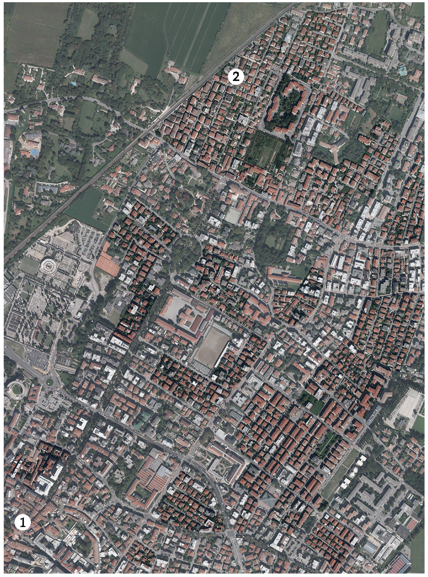
Mestre is a case study of sure interest in relationship to the aforementioned themes (
Figure 1). After originating as a fortress at the borders of Treviso and Venice territories, it later became and obliged passage between the mainland and the latter, as five major roads meet there [
40]. It gained some importance at the beginning of the 20th century with the creation of factories connected to the several military bases that existed there until recent times. In the late 1920s, Mestre was annexed to Venice and a large industrial facility was created in its territory, comprising a harbour, steel mills, petrochemical and chemical industries [
40,
41].
In absence of by-laws and as an answer to the housing needs of the ever-increasing population of the town, also coming from Venice, houses were built on every available space, starting from the existing roads; construction works were mainly promoted by private citizens. Until the 1980s, load-bearing URM construction was largely predominant, as clay bricks and hollow blocks were cheap and easily available from local producers; reinforced concrete (r.c.) was used mainly in horizontal structures or isolated pillars inside the external masonry walls. The URM building stock may be subdivided in the following broad classes:
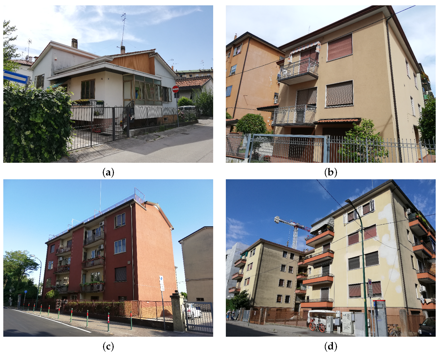
One- or two-storey working-class detached houses. Walls are made of clay bricks or blocks; later (since the 1970s), these latter were replaced by hollow concrete blocks. Floors consist of rib-and-slab, semi-rigid r.c. structures (see
Section 3.2), and roofs are composed of timber beams and clay tiles. This type is common from the 1950s to the 1980s (
Figure 2a);
Two- or three-storey middle-class buildings, either semi-detached or divided into flats, one for each floor. Construction features are similar to the previous type, but finishes and detailing are more accurate and architectural; solutions may be more elaborated (since the 1960s;
Figure 2b);
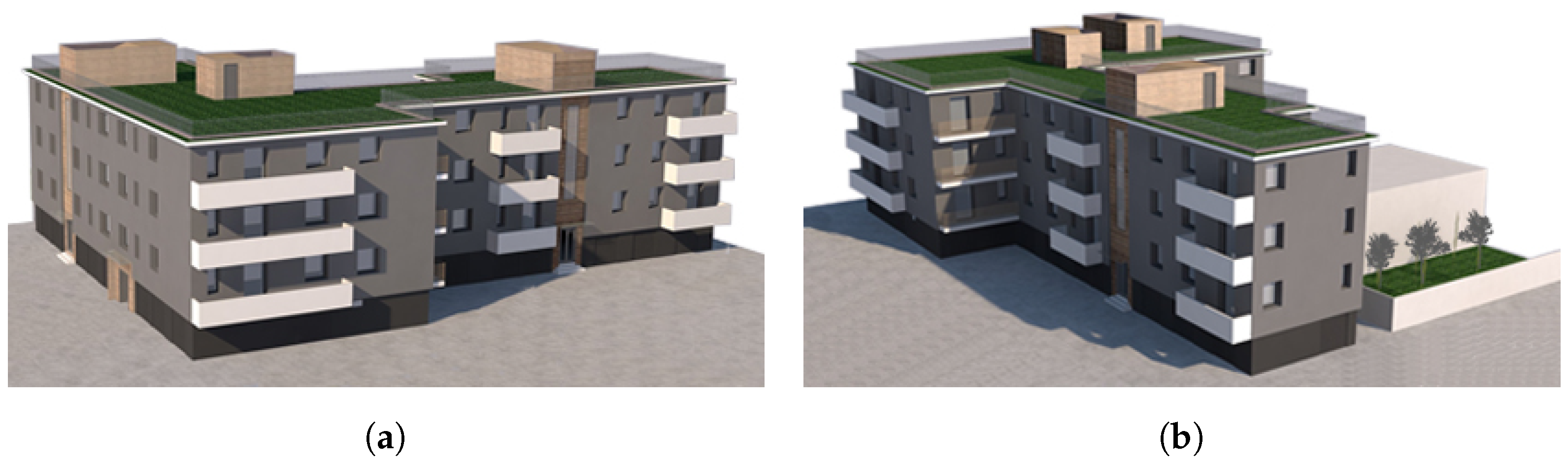
Three- to four-storey apartment buildings, with regular plan, generally rectangular, with one or two staircases and two or four flats per floor, respectively. Floor slabs are similar to those of the previous types but r.c. roof structures are widespread, especially in more recent buildings (1950–1970). As the ground floor hosts garages, ware rooms or shops there are often large openings at this level, and sometimes a r.c. frame is used, although only on the street façade (since the late 1950s;
Figure 2c);
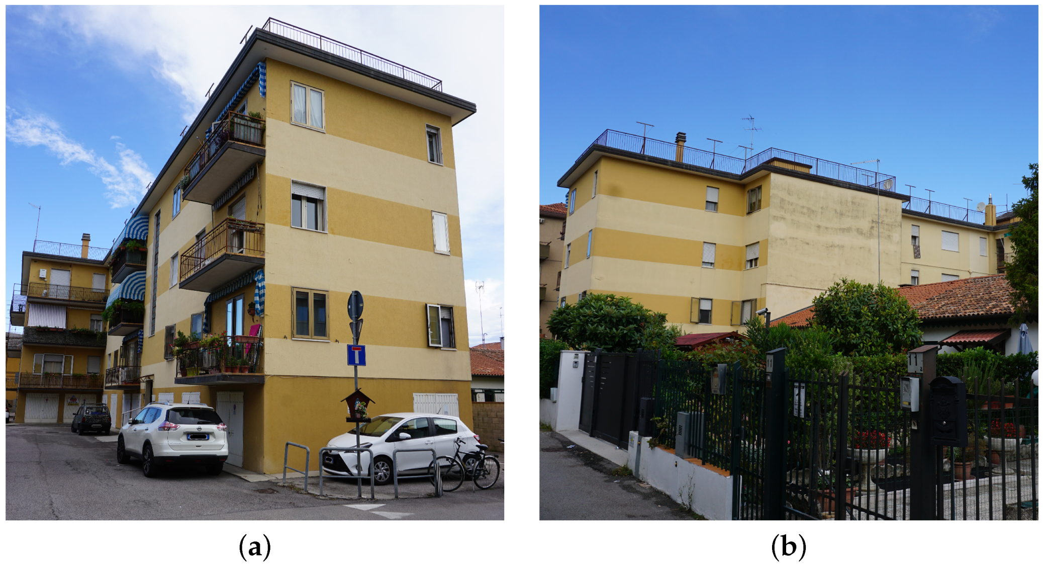
Apartment buildings similar to the previous type but irregular in plan (L or C shape), taller (up to 5 storeys) and with more than two staircases (since the 1960s;
Figure 2d)
As Mestre was never considered a seismic area, no specific provision was used in 20th century building practice. Vertical regularity is in general followed in every type, although in larger buildings, garage doors are generally not systematically aligned with the openings of the storeys above. Vertical additions of one or two storeys are also common, and in the case of apartment buildings, the external walls of additions are inset by about 2 m. Load-bearing walls’ thickness is generally limited to 28 cm, except for taller buildings (at least five floors), whose ground floor walls are increased to 42 cm.
A sampling in those neighbourhoods built after the Second World War and the following economic boom showed that about 70% of the stock corresponds to URM buildings (
Figure 1).
2.2. Methodological Approach
This work followed the methodology proposed by the Italian seismic codes for the assessment of the existing state of a structure [
18,
42,
43], which comprises: (a) perusal of archival documents; (b) geometric survey and comparison with blueprints; (c) definition of material properties and of a structural model; and (d) seismic safety assessment according to current standards. In the present case, uncertainties in the structural model, in both overall and local assessment, were considered.
Energy needs and consequent design proposal conformed to the stages proposed by [
44,
45]; it is worth noting that some tools, specifically thermographic analyses, yielded useful information for both structural and energy experts, and therefore these tools are to be considered as a staple in such integrated activities. The results of energy assessment were framed in current standards and practice [
46,
47].
3. Case Study
3.1. Architectural Characterization
The model building, henceforth referred to as ‘CSG building’ (
Figure 1 and
Figure 3), is a four-storey apartment building in the north residential zone of Venezia–Mestre belonging to the fourth building type (
Figure 2d). It was built in 1962–1963, and the perusal of the original documents shows some differences in finishing and the roof with the actual building, probably owing to a financial shortage in the final stages of construction. The external metric survey, however, confirmed that most of the measures given in original blueprints and internal inspections showed a good conformity of the present flats’ layout to that authorized in the 1960s as well. Therefore, this latter was assumed as valid for the entire building. The construction site is placed at the borders of the neighbourhood, close to a railway line.
The CSG building has a L-shaped plan reaching about
m: the north wing is 11.50 m deep and the western one is 7.1 m. The ground floor hosts garages, storage and technical rooms, whilst in upper storeys there are six apartments per floor, served by three separate staircases (
Figure 4). The internal layout of the flats is different, and their commercial surface ranges between85 and 90 m
2 (6 flats) and 105–110 m
2 (12 flats). The four-storey CSG building is 11.60 m tall, with an inter-storey height equal to 2.20 m and 2.80 m at the ground floor and the upper storeys, respectively; floor slabs are 25 cm thick. It covers a surface of about 580 m
2 for a total of 6728 m
3.
There is no elevator and no flat is accessible to handicapped people. The roof is flat, but it is scarcely used by the inhabitants.
3.2. Structural Characterization
In order to obtain a representative model of CGS buildings, inspections were carried out on-site according to the criteria given in
Section 2 with the help of a thermographic camera. Unfortunately, no direct testing of material properties was possible during the research project, and therefore the missing pieces of information were acquired from either the literature or available documents.
Foundations could not be inspected. According to the construction practice of that period (see, e.g., [
48,
49]), they were of the shallow type and the concrete strip had a small amount of steel reinforcement at the bottom face.
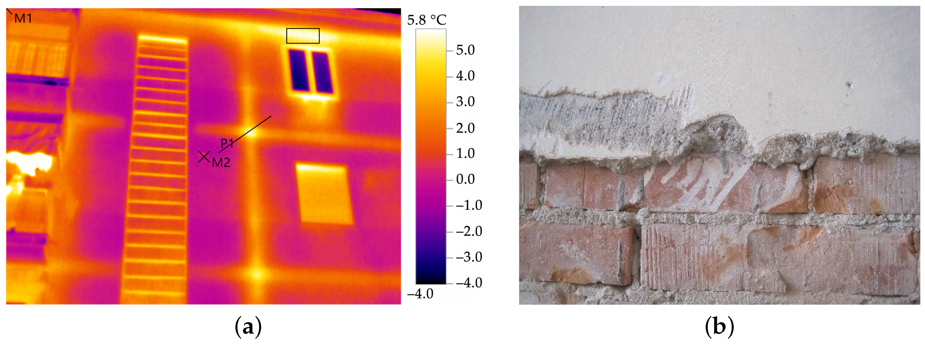
As confirmed by thermographic analyses, the vertical load-bearing structure consisted entirely of 26 cm thick, solid brick walls (
Figure 5a); the modularity of blocks is
cm, the percentage of voids 18%, and their declared U-value is 2.38 W/ m
2 K [
50] when applied to a 25 cm thick wall. A removal of the plaster revealed that bed joints were thicker than 1 cmm whereas head ones were often left empty; cement mortar was used (
Figure 5b).
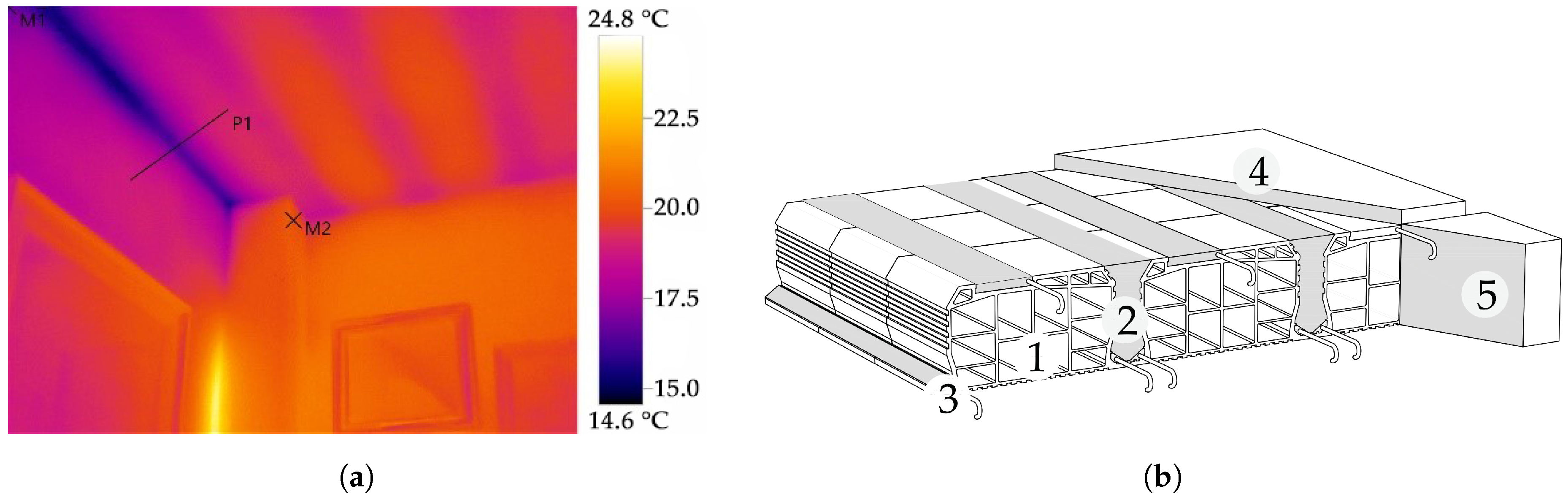
It was not possible to inspect the horizontal diaphragms in the same way. However, according to the documents, the period of construction and thermograms (
Figure 6a), they were most probably obtained from a composite system made of lightweight hollow clay blocks bound with cement mortar and reinforced with steel rods, thus forming the load bearing joists, alternating with unreinforced lightening ones [
48,
49]. In the space between load-bearing and replenishment joists, the resulting thin r.c. rib (<7 cm width) could host an additional rebar; a thin concrete slab, without the steel mesh (3 cm), completed the system on top (
Figure 6b; [
50,
51]). According to [
52] the clay top layer of joists could be considered as the compression slab and the concrete one served as a finish, as in this case. The rule of thumb of those times suggested a slab’s structural thickness about a 25th of the structural span, which is about 20 cm in CSG building.
At floor level, r.c. ring beams border the diaphragms, providing an adequate horizontal connection to walls; however, thermograms show that, on facades, these beams are interrupted by the staircases. The minimum longitudinal reinforcement of beams whose cross section was less than 2000 cm
2, as in this case, allowed by Italian standards [
52] was 0.8%. However, in manuals and producers’ brochures from the 1930s through the 1960s [
48,
49,
51] tie beams appear to be unreinforced or reinforced only at the bottom face; indeed, they only served as the anchoring of floor joist’s rebars. Similarly, no stirrups were there, as concrete only was entrusted of the required shear strength. At the ground floor, the belt is deeper (about 40 cm) since it must bear the weight of the walls above garage doors, which are about 2 m wide; at upper levels it is as thick as floor slabs.
All the information collected account for the building’s limited knowledge (Knowledge Level 1) and therefore a Confidence Factor CF = 1.35 [
42,
43], which reduces the mechanical properties of materials (i.e., masonry and r.c.) in structural models.
3.3. Model Definition
No mechanical testing was possible on materials, and therefore their mechanical properties were determined by referring to data available in the literature. Uncertainties of materials and other characteristics of CSG buildings were not systematically inspected and were dealt with by considering different models, varying materials and modelling strategies.
Masonry did not correspond exactly to those types listed by [
18], as it is intermediate between the types ‘solid bricks with lime mortar’ and ‘clay blocks with void ratio less than 40%’; to consider the relevant thickness of bed joints and the likely usage of lime in addition to cement for the making of mortar, the reducing factors allowed by [
18] were applied, i.e., 0.7, to strength properties and 0.8 to elastic moduli. Masonry properties are listed in
Table 1, according to the criteria stated by [
18] when KL = 1. In the global assessment, according to [
43], half of the elastic properties were considered in order to simulate the damage reached by a building in seismic conditions.
Spandrels and piers share the same masonry material, but they were reduced on façade walls when radiators were installed; therefore, two possible variations were considered, i.e., with spandrels as thick as piers (28 cm) and half as thick (14 cm); in the latter case, tie beams needed to be added in the model at floor level to simulate a minimum tensile strength. Tie beams are actually unreinforced, but a minimum amount of additional reinforcement was required (4Ø6 longitudinal bars and no stirrups). Finally, the last variation considered the in-plane shear stiffness of horizontal diaphragms, which governs the coupling between transversal walls, as no experimental data were available on such a property for semi-rigid r.c. slabs as those of CSG building. Besides a minimum value of G = 1 MPa, a finite value of G = 300 MPa was considered. This latter value, as well as the longitudinal elastic modulus E = 1200 MPa, was inferred from [
53] assuming the ribbed clay floor slab equivalent to a modern lightweight block masonry, with a percentage of voids in between 45 and 65%. The resulting models are shown in
Table 2.
As for r.c.properties, [
54] suggest the usage of f
y = 356.5 MPa and f
u = 518.6 MPa as the yield and the ultimate strength of steel rebars, respectively, when just the age of construction is known, i.e., the early 1960s.
The project description of the CSG building stated the usage of a structural concrete with R
ck = 25 MPa. The maximum Confidence Factor was also applied to these properties. Structural loads (g
k1) were determined from buildings manuals (e.g., [
50,
51]), and non-structural permanent loads (g
k2) were estimated in 100 kg/m
2 on floor slabs by considering an old-fashioned floor tiling and a distributed load equivalent to non-structural partitions as allowed by [
43], and in 50 kg/m
2 on the flat roof, considering a simple waterproof layer. Live loads were assumed equal on each slab, as the roof is commonly accessible by inhabitants.
Table 3 resumes floor loads and the combination coefficient valid for seismic conditions.
Figure 7 shows the equivalent frame model of CSG building.
The seismic input, for ordinary civil buildings, was defined by [
43] (
Table 4) considering a C class soil for the building’s site [
42], as proposed by [
55].
3.4. Equipment Characterization
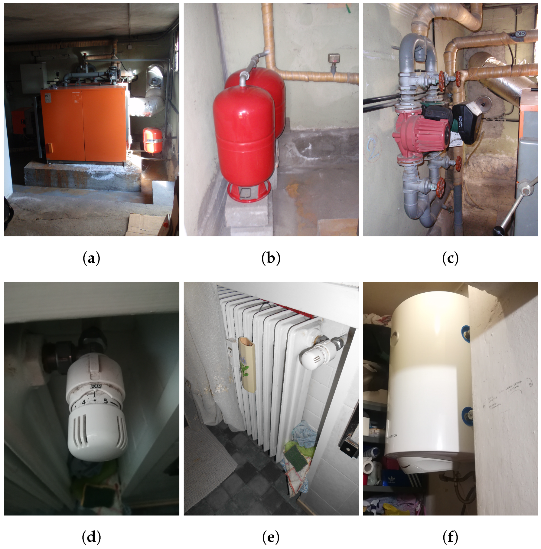
At the time of construction, central heating systems and radiators were not mandatory in flats and, consequently, heat was supplied by fuel oil or coal powered stoves. In CSG building, a central hydronic heating system, connected to the public methane network, was only installed in 1978 (
Figure 8). Radiators were placed in niches below windows, carved in the walls on that occasion; they have recently each received thermostats, in compliance with European standards [
56]. In fact, the distribution piping was vertically shared among the flats, and it ran mostly on the facades. The central heating also warmed tanks in individual flats during winter, for the supply of hot water for sanitary uses. In summer, such tanks served as electrically operated boilers. Piping was not insulated, and the gas supply system did not comply with present standards any more.
Other common facilities were limited to pumps for circulation of the fluid in the hydronic system and water supply and lighting of common spaces, since the TV antenna was individual for each flat; the lack of an elevator limits the mobility of the senior inhabitants of the CSG building.
Wiring was largely obsolete, unsafe and not adequately protected from accidental contact. Not to mention wires pertaining to individual flats, those shared among them were chaotic and invasive: the several antennas on the roof, as each flat had one, prevented their use for recreational purposes.
4. Present State Assessment
4.1. Global Seismic Behaviour
A CSG building’s overall seismic behaviour was assessed by the means of 3Muri software [
57]. The software allows one to carry out non-linear static (pushover) analyses to obtain a building’s capacity curves, i.e., the relationship between the base shear force and the displacement of a control node, in both the building’s main directions and according to two different distributions of horizontal loads, proportional to floor masses (i.e., uniform) or to the height (i.e., triangular). A three-dimensional model of a CSG building, idealized according to the equivalent frame approach [
58], was defined considering the possible variations of its features presented in
Table 2. In this framework, the non-linear behaviour of masonry elements (piers and spandrels), lumped at both ends and at the midsection, is modelled through a piecewise relationship between the drift ratio and the horizontal force. The shear behaviour of both piers and spandrels was considered to be governed by the diagonal cracking failure mode, as defined by [
59,
60]. The flexural behaviour was assumed from beam theory, as proposed by the Italian technical standards [
43]. Reinforced concrete elements were modelled as non-linear beams by assuming elastic perfectly plastic hinges concentrated at the end sections [
61]. Floor diaphragms were converted into three- or four-node plates with an equivalent in-plane and shear elastic moduli, which the mutual structural link among piers of the same wall and between orthogonal walls depend on.
Pushover analyses were carried out on both the main directions of CSG building and with the two possible distributions of horizontal loads; since it had semi-rigid floors, a 5% accidental eccentricity between the centres of masses and stiffness was considered [
43].
On the pushover curves, the main overall limit states (
LS) were determined according to the criteria given by [
18], that is: (a) Near Collapse (NC), when a 20% shear strength decay happened; (b) Severe Damage (SD), as 75% of NC displacement; and (c) Damage Limitation (DL) at the yield displacement. For each
LS, the corresponding capacity Peak Ground Acceleration (
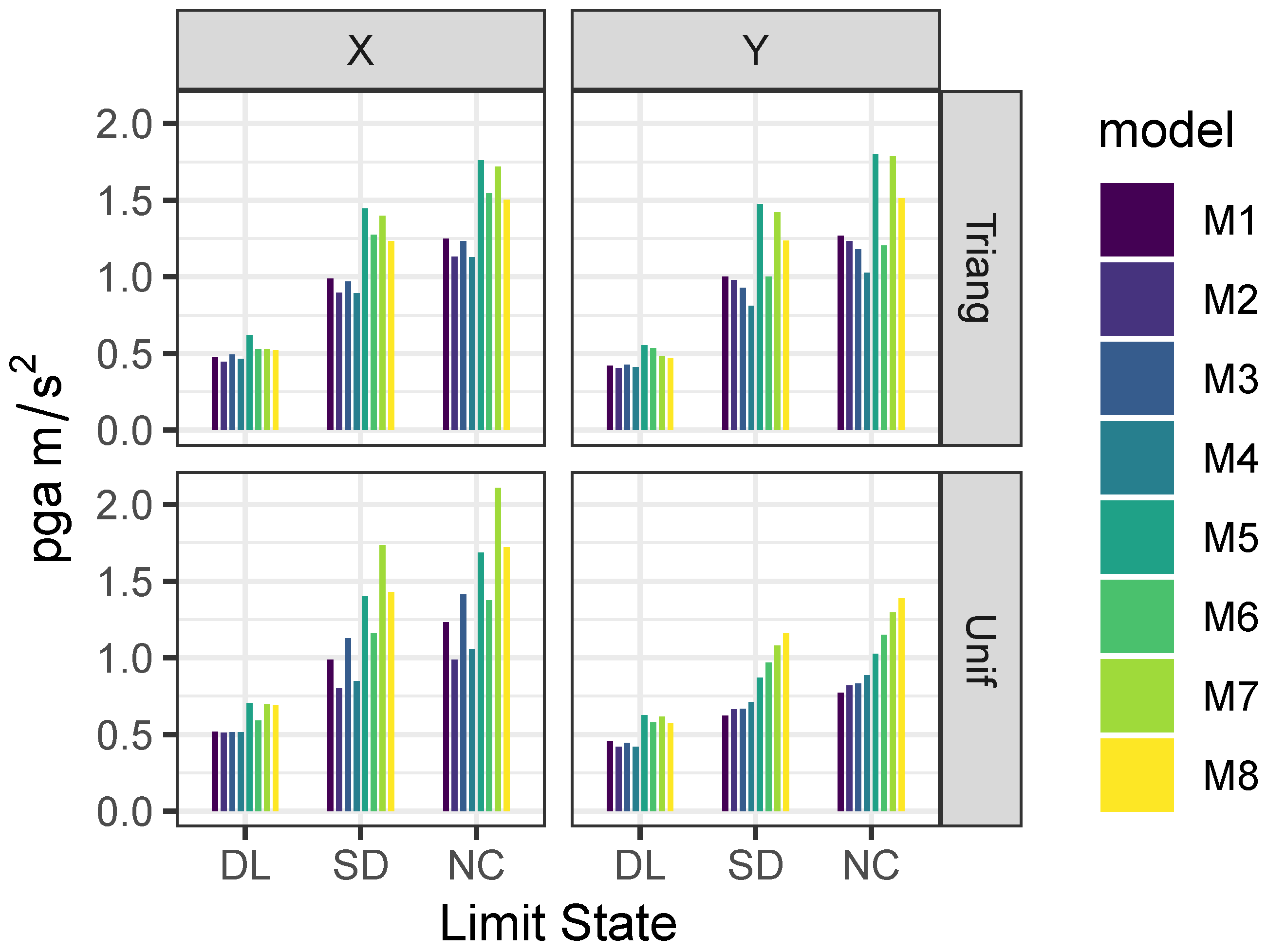
PGA) was obtained through the application of the N2 method [
62] (
Figure 9).
One may observe in
Figure 9 that (a) the models with solid bricks masonry had a poorer performance than those with clay blocks; (b) the influence of the masonry type was greater than the coupling degree allowed by spandrels in the two models; (c) the Y direction was weaker than the X one; (d) uniform analyses led to lower
PGA values at each
LS, owing to the large openings at the ground floor; and (e) in-plane shear stiffness of floor diaphragms worsened the building’s seismic performance, as
PGA was generally lower for these models (compare, e.g., M1 and M2).
4.2. Local Seismic Behaviour
In CSG building, activation of local mechanisms should have been inhibited by the systematic presence of ring beams and the supposed good mutual connection between walls. These factors influenced the simplest local mechanism, e.g., global wall overturning, but other modes, e.g., vertical bending or the horizontal arch in a wall’s thickness, were still possible in each masonry panel.
Vulnus software [
24] can evaluate the load multiplier
c of seven local mechanisms, distinguished in ‘vertical’ and ‘horizontal’ mechanisms, also considering openings (i.e., doors and windows) and their distance from corners and walls’ intersections. A building is idealized into walls, which are subdivided into panels delimited by nodes at the two ends (
Figure 10).
Vulnus detects that panel whose ‘out-of-plane index’ (I
2), i.e., the sum between the minimum
c value for the two types of mechanisms, is the minimum. Therefore, this index represents the out-of-plane strength of a building. An ‘in-plane index’ (I
1) describes the shear strength of masonry piers according to a method proposed by [
63], as a normalized value in a building’s two main directions. Finally, a third index (I
3), obtained from the correlation with a vulnerability assessment procedure originally proposed by [
64], qualifies the asset according to empirical rather than mechanical parameters, e.g., maintenance conditions, non-structural elements, plan or elevation regularity.
Thanks to its simple application and the little amount of information requested, the software is a useful tool for expeditious vulnerability assessment, especially in the case of urban scale analyses [
65,
66].
Vulnus considers a type-floor plan, which should be the weakest one, i.e., that which presents the largest openings. In CSG building, there is a huge difference between the ground floor and the upper storeys, and therefore both levels were considered; moreover, for the sake of simplicity, the building was split into its north and west wing.
The in-plane index pointed out the X direction as the weakest in the north wing, at both ground and residential floor, and the ground floor in the west wing. The weakest direction was Y in the floor type of the west wing. In respect to out-of-plane mechanisms, the weakest panel was n. 1 in wall 15 in the north wing and n. 1 in the west wing; this happened in both the ground and the type floor. The empiric vulnerability index I
3 was similar for the two wings of the buildings and showed a low-vulnerability condition (
Table 5).
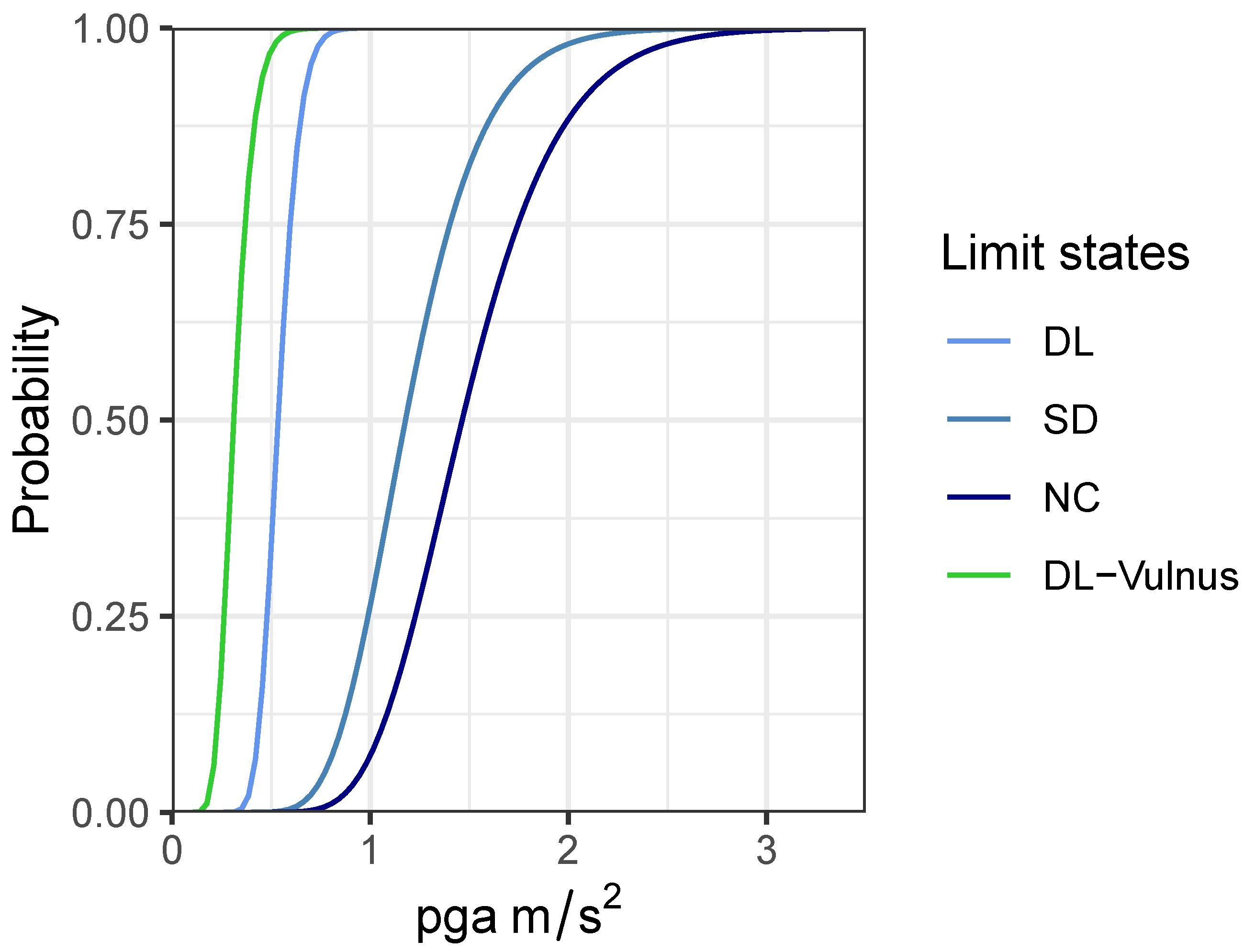
Definition of Fragility Curves
Fragility curves define the probability of reaching a limit state (
) of structural interest as a function of a certain seismic intensity measure, in this case, the
PGA. Assuming a lognormal distribution, the probability that the limit state
reached by a building is greater than the
i-th limit state (DL, SD, NC) at a certain value of
is expressed as (
1):
where
is the demand peak ground acceleration,
the standard normal cumulative distribution function,
is the median value of the capacity of the asset to resist to limit state
, and
is the standard deviation of the natural logarithm of the capacity (
Table 6).
Fragility curves were obtained from pushover analyses according to the procedure proposed by [
22,
67], starting from the
PGA (
Figure 9) values that determined the reaching of each limit state (
Figure 11).
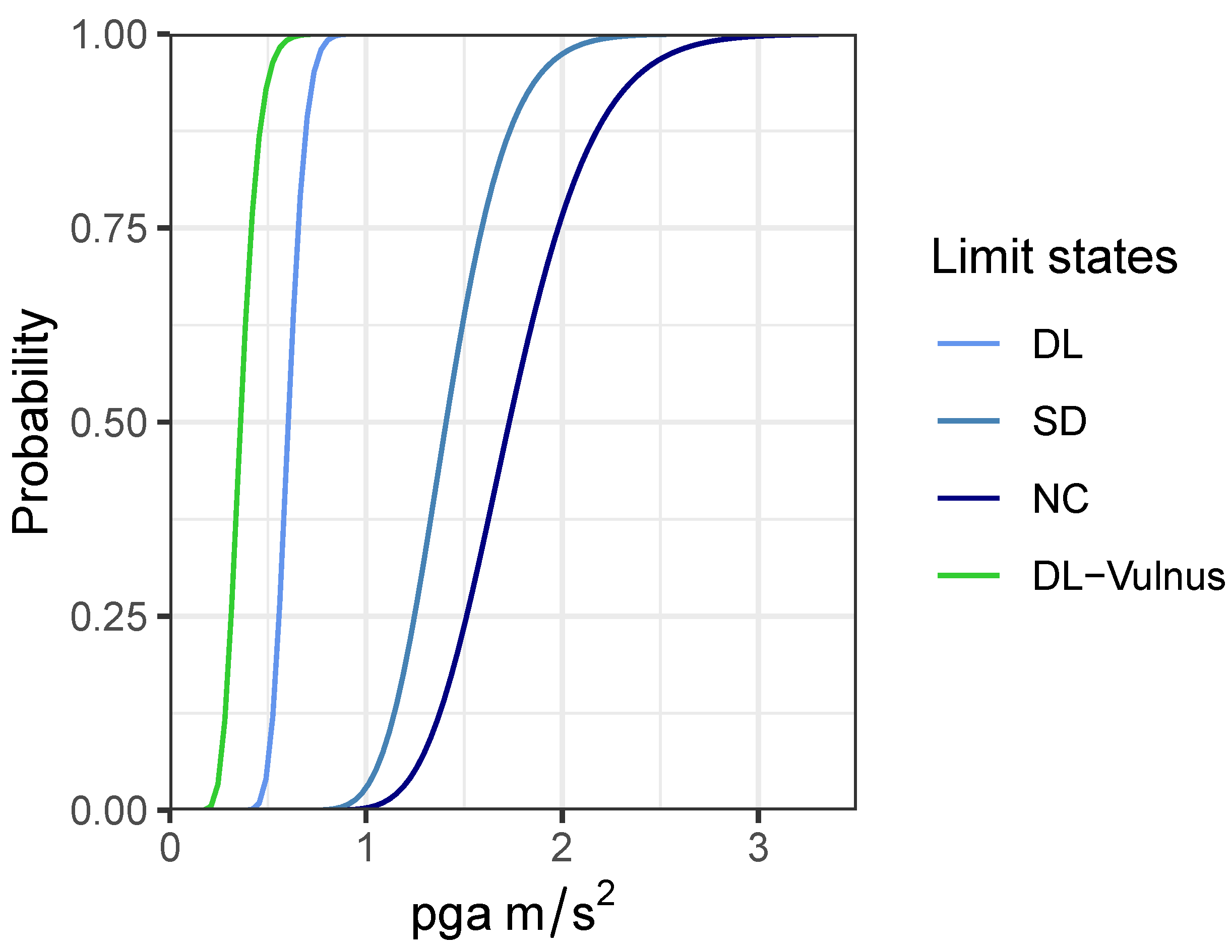
The fragility curves obtained from the overall assessment were compared to the only one automatically calculated by Vulnus by the means of fuzzy sets [
24]. As this curve (green line in
Figure 11) describes the activation of local mechanisms, it corresponds to a damage state D2–D3 (moderate damage, [
68]) and, in terms of safety verification [
43], to a DL limit state. Indeed, the ‘Vulnus’ fragility curve is moved to the left of the graph, and it is comparable to the DL curve of the global assessment. For the
PGA at SD limit state expected in Mestre, CSG has a moderate probability to exceed the SD limit state (about 20%) but a high probability to reach and exceed the DL, on either local mechanisms or the overall shear behaviour.
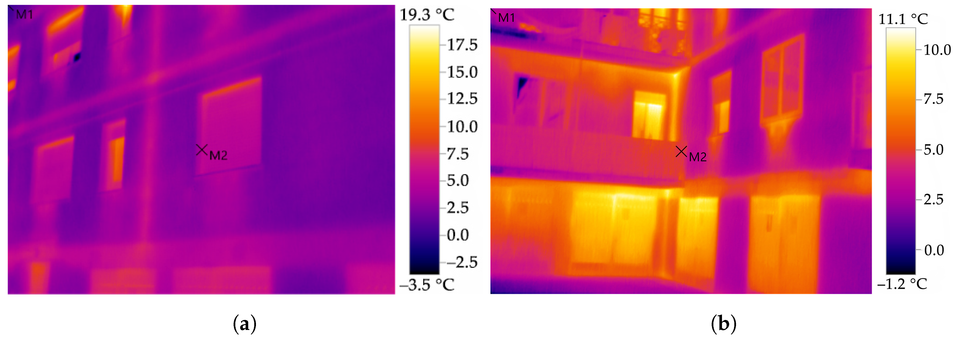
4.3. Energy Needs
The thermal behaviour of CSG building was assessed by means of thermographic inspections and finite element simulations.
On-site surveys revealed the considerable amount of heat dispersed by external walls, especially in the niches below windows (where radiators were placed) and in corners; the traces of floor slabs on internal walls were also clearly visible in thermograms (
Figure 12). The heat dispersion, combined with the high RH measured (65–72.2%) inside the flats at the time of the surveys (February 2019), determined an extensive presence of dew and mould on internal surfaces. These conditions were a proxy of the uncomfortable indoor climate in CSG’s flats.
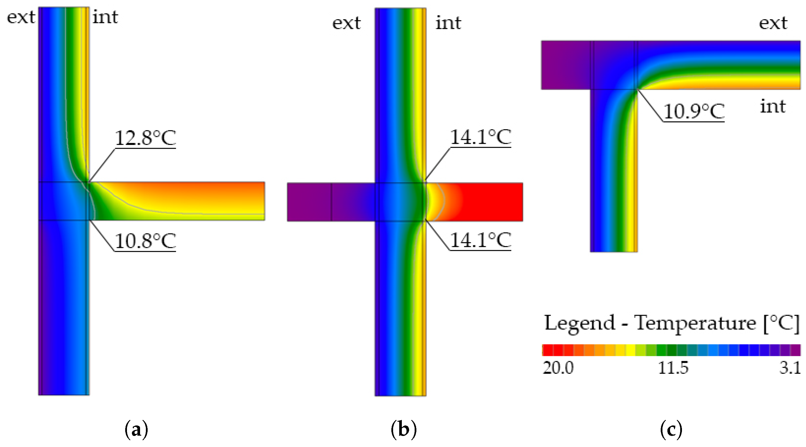
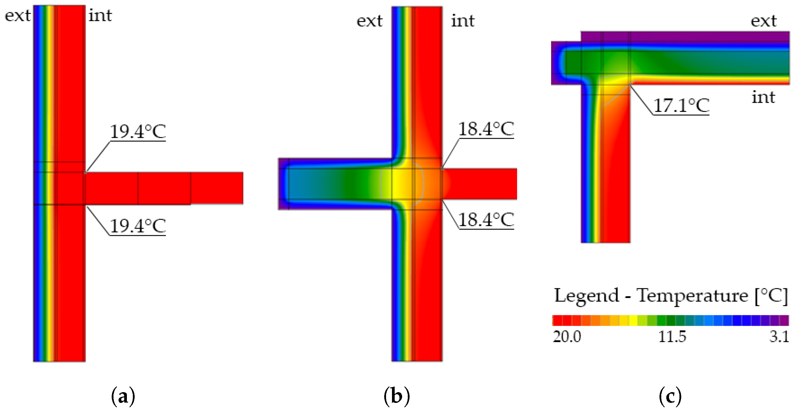
Indeed, thermal finite element analyses with IRIS software package [
69] confirmed low temperatures on internal surfaces (10–14) °C close to the dew temperature, especially in the junctions between floor slabs and walls and between the roof and the walls. Due to the high internal RH, the software confirmed the possible presence of mould on cold surfaces (
Figure 13).
Static and dynamic thermal analyses were carried out by means of PAN software [
70] according to the calculation criteria defined by international standards; climate data and predefined material properties complied with Italian and international definitions, respectively. The software also checked whether the existing stratigraphy of walls fulfilled the current Italian standards [
71].
The overall energy need amounted to 238.07 kWh/m2 year.
The properties of materials used in this work are given in
Table 7, and the stratigraphy of each enclosure was determined during on-site surveys.
The enclosures’ U-value, before interventions (plaster, masonry, plaster), was determined as 1.69 W/m
2 K, larger than the reference one for the climate zone (0.22 W/m
2 K); in simulations, the dew and mould formation temperatures were reached in January and October, respectively. In summer conditions, the superficial temperature on the interior of the enclosure was estimated at 26 °C, which was considered to exceed the comfort conditions as well. For the sake of completeness, staircase’s walls transmittance was assumed as 1.46 W/m
2 K but the confrontation term (walls in common between buildings) was 0.80; dew and mould verification showed satisfactory conditions. The floor slab U-value (see
Section 3.2) was estimated at 1.4 W/m
2 K, larger than the prescribed values of 0.22 (roof) and 0.26 W/m
2 K (first floor, above garages); simulations did not reveal the formation of either mould or dew in this case.
4.4. Asset Value and Management Costs
4.4.1. Asset Value
The commercial value of the flats, estimated independently from garages, was appraised both through a sales comparison and an income approach, which were then compared; however, the second method seemed more reliable owing to the type of real estate. The market price estimated was 1100 EUR/m
2 (in 2019), which yielded the values shown in
Table 8. The total value of the flats amounted to a little less than EUR 2 million.
4.4.2. Management Costs and Annual Energy Expense
Based on four-year statistics on the actual expenses of the inhabitants, the operation of the centralized boiler requires about 2000 m3 methane gas and 1200 kWh of electricity per year, which implies an expense of EUR 18,460 and EUR 710 respectively; its maintenance amounts to about EUR 1040. The expense for private boilers for hot water supply in each flat sums to EUR 11,700. Electricity for common facilities amounts to EUR 640 per year. Overall, the total energy expense amounts to 32,540 EUR/year, which is an average monthly instalment of 150 EUR per flat.
5. Proposal of Interventions
Indoor comfort conditions and the response to solar radiation and site issues (e.g., the railway line close by) governed the proposal of interventions. Other criteria were the re-definition of the overall image of CSG building, also considering the neighbourhood scale and the valorization of its common spaces.
5.1. Architectural Renewal
To the general end of conveying a new image of CSG building, a rainscreen system was applied to the added cladding of the walls. The material chosen for the screen were ceramic tiles, durable and available in a wide variety of renders and colours. Consequently, tiles with a different texture and lighter colour marked the staircases of the building, whereas a darker colour in the ground floor characterized it as a pedestal for the building upon it; moreover, as there was no thermal cladding on the walls of the ground floor, the small recess emphasized this effect (
Figure 14).
The installation of a new lift was only possible in staircase 2, thus making six flats accessible. This would help their present inhabitants but also increase their commercial value.
The design proposal was completed by a green roof on top of the building in order to take advantage of the reduction in direct solar radiation and to increase the winter insulation of the roof [
72]. Moreover, it would offer a new common space to the inhabitants of CSG building, which now is missing. The choice of an extensive solution was governed by the reduction in both structural weight on the load-bearing walls and maintenance costs after its installation.
5.2. Structural Retrofit
Structural interventions took advantage of the results of both local and global seismic assessment. In addition to market prices of the inspections carried out during the assessment phase, some geotechnical tests were hypothesized and considered in the final cost estimate (see
Section 6).
Owing to the possible activation of horizontal flexure in the longest masonry panels on both wings of CSG buildings, tie rods were proposed at their midspan (
Figure 15a). Steel strips, bolted to internal transverse walls, were anchored by plates to external walls. These plates were designed to have the lowest thickness possible, in order to be covered by the thermal cladding.
The overall seismic assessment showed the weakness of masonry piers at the ground floor as well a concentration of damage in those walls with an unfavourable geometrical configuration, such as the south façade of the west wing. Therefore, the strengthening solution, compatible with the thermal cladding, was the application of fibre-reinforced polymer strips bounded with organic resins to masonry walls. Strips would compose a ’braced frame’ spanning over the inter-storey height (
Figure 15b), adding the required shear strength to walls, with a limited interference with moisture diffusion from the indoor air.
Fragility curves were also computed in design conditions, revealing a limited vulnerability reduction (
Figure 16), in both the local and overall behaviour. Indeed interventions were concentrated in common parts of CSG buildings, and they were limited to the essential in individual flats, in order to minimize the impact on flat’s usage. Moreover, interventions were constrained by the low seismic input, which reflected on both the little amount of reinforcement needed to meet the seismic safety requirements [
43] and the impossibility of tax deduction (see
Section 6) for such interventions.
5.3. Energetic Retrofit
The energy retrofit solution consisted of a 20 cm thick rock wool cladding of all external walls. Rock wool was preferred on other insulating materials owing to its fire resistance [
73], good thermal properties, and a low moisture permeability, which did not alter the humidity balance of CSG building; moreover, in design conditions, the moisture that seeped in walls would be removed by the chimney effect of the ventilated facade. Finally, thanks to its mass and the open cells of it structure, rock wool offered acoustic protection to the noise coming from the railway nearby.
In order to deliver a complete intervention, minimizing cold bridges, the intrados of floor slabs on the ground floor was covered with a low-thickness, high-performance insulating panels (e.g., aerogel); walls of staircases were treated in a similar way. Balconies were insulated from the intrados with rock wool (
Figure 17).
The design stratigraphy of the envelope complied with the code requirements with U = 0.16 W/m2 K and, in both winter and summer, the superficial temperature on the internal side of the walls was 20 °C, i.e., a comfort condition.
Existing fixtures were replaced by new ones with PVC casements and with low-emissivity glass panes on the north façade and selective glasses on the west and south ones.
The green roof integrated with the overall energy retrofit intervention, as it would limit solar gain in summer and heat dispersion in winter, thus helping the overall thermal balance of CGS building.
5.4. Heating and Ventilation Systems
The hydronic system was completely renewed in a design proposal. Two condensing boilers replaced the existing one, and new insulated distribution piping was proposed. The gas supply and the technical rooms were updated to current standards.
Individual boilers for hot water supply in summer were replaced by air-to-air heat pumps, taking heat from indoor air.
Finally, for a better control on indoor climate, ventilation units with pre-heating of incoming air were proposed in each flat.
5.5. Photovoltaic System and Wiring
A photovoltaic system was placed in the northwest corner of CSG building’s roof, which an irradiance analysis proved to be the most advantageous spot. Ten modules, for a total surface of 16.40 m2, were estimated to produce 3431 kWh of electricity to power the hydronic system. The common wiring as well as the lighting fixture were replaced with new parts that were safer, more efficient and compliant with current standards.
6. Discussion and Results
The expenses for interventions were organized in items and subitems according to the tax break they would benefit by: general repairs and structural interventions at 50% and energy retrofit at 75% (
Table 9). At the time of the design, Mestre, as the whole coastal area of Veneto, was excluded from special incentives on structural interventions aimed at seismic retrofitting [
36]. The cost for seismic retrofit also included the finishing works.
To the direct expenses were added the following: 2% unforseens, 10% VAT, 11% professional fees, 2% administrative fees, 28% professional welfare and other taxes. The total expense amounts to EUR 1.21 million, i.e., 67,450 EUR per flat or 525 EUR/m2. Of these, EUR 253,000 would benefit from a tax break at 50% (structural and architectural works) and EUR 1,064,550 at 75% (energy retrofit).
After interventions, the increase in valuation of flats was appraised a 25% for dwellings served by staircases 1 and 3, and 35% for those served by staircase 2, where the new lift would be installed. Those values were obtained by comparison with market prices of similar dwellings, either new or resulting from renovations. The total added value is EUR 562,880.
The less energy needs, prudentially considered, determined an annual expense reduction of about EUR 23,800 (8420 EUR/year,
Table 10), i.e., 110 EUR/year per flat.
Finally, two approaches were considered for managing the costs of the renewal works: (a) ordinary loans and (b) transfer of receivables to a third-party company. In financial plan (a), the inhabitants were supposed to entirely make use of the tax deduction, and therefore they could have access to individual loans at a 5% discount rate, which corresponded to the 10-year period of tax deduction for such operation of retrofit. The additional tax deduction on borrowing interest on loans amounted to 19% and was also considered in this scenario. The monthly instalment was 775 EUR per flat, but by detracting tax breaks and less energy expense, the actual expense amounted to EUR 205. Considering the cash flows during a 10-year financial plan, which is the maximum period allowed by Italian laws for such operations, the net present value (
NPV) of CSG building was calculated according to Equation (
2)
where
t is the number of years of the financial plan,
the cash flow and
i the weighted average cost of capital, estimated in 1%. In plan (a)
NPV amounted to EUR 135,480, i.e., 7525 EUR per flat.
In plan (b), a part of the tax credits due to retrofit interventions, estimated at 80% of the total figure, was transferred to a third-party company, considering the income of the inhabitants was insufficient to cover the tax break. The resulting monthly instalment for the loan was lighter (400 EUR/flat) than financial plan (a), but since tax deduction was less and costs had a different incidence, the resulting expense amounted to 215 EUR/month per flat. In these conditions, the NPV for the whole building was EUR 117,900, i.e., EUR 6550 per flat once the debt was paid (10 years).
7. Conclusions
The paper presents a case study of a 20th century unreinforced masonry multifamily building placed in Mestre, Northeast Italy, whose energy needs and seismic vulnerability were assessed. This work is framed in a project aimed at providing ’good practices’ for practitioners and professionals in the field of engineering, architecture and energy management.
The assessment procedure was carried out according to current standardized procedures in each disciplinary field of the research. However, a more advanced approach was followed in seismic vulnerability assessment, which considered uncertainties in both local and overall behaviour of the case study through fragility curves. This helped in revealing a moderate-to-low vulnerability, in spite of the low input expected for the design site: a 20% probability of reaching or exceeding the Severe Damage limit state was found, and even higher, when local mechanisms were considered.
However, the biggest issues came from the energy needs, which amounted to 238 kWh/m2 year, and uncomfortable indoor conditions; in addition, equipment, wiring and piping proved to be obsolete and unsafe.
Retrofit interventions are proposed as an integrated strategy to improve the case study seismic performance, minimizing the impact on inhabitants and exploiting available common parts, as well as to reduce its energy needs. The seismic vulnerability reduction was not so evident, although safety requirements were fully met. The application of an external cladding, combined with a smart façade, allowed warmth leaks in winter and heat built-up in summer to be eliminated, and the replacement of equipments and piping allowed the possibilities of high performance generators to be exploited. The final energy needs were estimated at 36.2 kWh/m2 year with a 84.8% reduction from the current conditions. The expenses for interventions were estimated in 565 EUR/m2.
In compliance with the Italian legal framework of such operations, a 10-year financial plan was then considered, according to two possible scenarios (individual loans or transfer of receivables), showing that the less energy needs and the tax incentives on such operations determined an affordable monthly expense of EUR 200. A positive net present value of each dwelling unit was estimated at the end of the financial plan.
The positive economic values obtained would promote the settlement of new inhabitants in the case study, as well as in similar buildings that underwent analogous refurbishment interventions. Although a higher attractiveness of houses can reduce the depopulation phenomenon described in the Introduction, it is the authors’ opinion that a trend inversion would only be promoted by a larger public effort in the redefinition of the surrounding urban environment (e.g., parking lots, common spaces, public lighting and footpaths).
Author Contributions
Conceptualization, A.T., C.B., C.T., I.M., G.D.S. and M.S.; methodology, M.S., L.S., G.D.S.; software, C.B., G.D.S. and L.S.; validation, L.S., G.D.S.; formal analysis, L.S.; investigation, A.T., C.B., C.T., I.M., L.S., M.S. and G.D.S.; resources, A.T., C.B., C.T., I.M., M.S. and G.D.S.; data curation, G.D.S., M.S. and L.S.; writing—original draft preparation, L.S.; writing—review and editing, L.S.; visualization, L.S. and C.B.; supervision, M.S. and C.B.; project administration, M.S.; funding acquisition, A.T., C.B., C.T., I.M., G.D.S. and M.S. All authors have read and agreed to the published version of the manuscript.
Funding
This research was funded by Confartigianato Imprese-Città Metropolitana di Venezia.
Institutional Review Board Statement
Not applicable.
Informed Consent Statement
Not applicable.
Data Availability Statement
Data sharing not applicable.
Acknowledgments
The authors wish to thank Ylenia Saretta for her technical support to the manuscript revision.
Conflicts of Interest
The authors declare no conflict of interest. The funders had no role in the design of the study; in the collection, analyses, or interpretation of data; in the writing of the manuscript, or in the decision to publish the results.
References
- Calafati, A. Urban Sprawl Italian Style. Ital. J. Reg. Sci. 2008, 3. Available online: https://ssrn.com/abstract=1831742 (accessed on 30 June 2021).
- Romano, B.; Zullo, F.; Fiorini, L.; Ciabò, S.; Marucci, A. Sprinkling: An Approach to Describe Urbanization Dynamics in Italy. Sustainability 2017, 9, 97. [Google Scholar] [CrossRef] [Green Version]
- Travisi, C.M.; Roberto Camagni, R.; Nijkamp, P. Impacts of urban sprawl and commuting: A modelling study for Italy. J. Transp. Geogr. 2010, 18. [Google Scholar] [CrossRef]
- Crisci, M.; Gemmiti, R.; Proietti, E.; Violante, A. Urban Sprawl e Shrinking Cities in Italia. Trasformazione Urbana e Redistribuzione della Popolazione nelle aree Metropolitane; CNR—Istituto di Ricerche sulla Popolazione e le Politiche Sociali: Rome, Italy, 2014. [Google Scholar] [CrossRef]
- Disposizioni per il Contenimento del Consumo di Suolo e Modifiche Della Leggere Regionale 23 Aprile 2004, n. 11 “Norme per il Governo del Territorio e in Materia di Paesaggio”, Regional Law No. 14, Veneto Region, 2017. Available online: https://bur.regione.veneto.it/BurvServices/pubblica/DettaglioLegge.aspx?id=346720 (accessed on 30 June 2021). (In Italian).
- Sassu, M.; Stochino, F.; Mistretta, F. Assessment Method for Combined Structural and Energy Retrofitting in Masonry Buildings. Buildings 2017, 7, 71. [Google Scholar] [CrossRef] [Green Version]
- Caruso, M.; Pinho, R.; Bianchi, F.; Cavalieri, F.; Lemmo, M.T. Integrated economic and environmental building classification and optimal seismic vulnerability/energy efficiency retrofitting. Bull. Earthq. Eng. 2021, 19, 3627–3670. [Google Scholar] [CrossRef]
- Bernardini, A.; Valluzzi, M.R.; Modena, C.; D’Ayala, D.; Speranza, E. Vulnerability Assessment of the Historical Masonry Building Typologies of Vittorio Veneto (NE Italy). Boll. Geofis. Teor. Appl. 2008, 49, 463–483. [Google Scholar]
- Betti, M.; Bonora, V.; Galano, L.; Pellis, E.; Tucci, G.; Vignoli, A. An Integrated Geometric and Material Survey for the Conservation of Heritage Masonry Structures. Heritage 2021, 4, 585–611. [Google Scholar] [CrossRef]
- Valluzzi, M.R.; Sbrogiò, L.; Saretta, Y.; Wenliuhan, H. Seismic Response of Masonry Buildings in Historical Centres Struck by the 2016 Central Italy Earthquake. Impact of Building Features on Damage Evaluation. Int. J. Archit. Herit. 2021. [Google Scholar] [CrossRef]
- D’Ayala, D. Assessing the seismic vulnerability of masonry buildings. In Handbook of Seismic Risk Analysis and Management of Civil Infrastructure Systems; Goda, K., Tesfamariam, S., Eds.; Woodhead Publishing: Sawston, Cambridge, UK, 2013; pp. 334–365. [Google Scholar] [CrossRef]
- Riuscetti, M.; Carniel, R.; Cecotti, C. Seismic vulnerability assessment of masonry buildings in a region of moderate seismicity. Ann. Geophys. 1997, 40, 1405–1413. [Google Scholar] [CrossRef]
- Shabani, A.; Kioumarsi, M.; Zucconi, M. State of the art of simplified analytical methods for seismic vulnerability assessment of unreinforced masonry buildings. Eng. Struc. 2021, 239. [Google Scholar] [CrossRef]
- Calderoni, B.; Cordasco, A.E.; Del Zoppo, M.; Prota, A. Damage assessment of modern masonry buildings after the L’Aquila earthquake. Bull. Earthq. Eng. 2020, 18, 2275–2301. [Google Scholar] [CrossRef]
- Saretta, Y.; Sbrogiò, L.; Valluzzi, M.R. Seismic response of masonry buildings in historical centres struck by the 2016 Central Italy earthquake. Calibration of a vulnerability model for strengthened conditions. Constr. Build. Mat. 2021, 299. [Google Scholar] [CrossRef]
- Simões, A.; Bento, R.; Cattari, S.; Lagomarsino, S. Seismic Performance-Based Assessment of “Gaioleiro” Buildings. Eng. Struct. 2014, 80, 486–500. [Google Scholar] [CrossRef]
- Milosevic, J.; Bento, R.; Cattari, S. Seismic Behavior of Lisbon Mixed Masonry-RC Buildings With Historical Value: A Contribution for the Practical Assessment. Front. Built Environ. 2018, 4. [Google Scholar] [CrossRef] [Green Version]
- Istruzioni per l’Applicazione dell’Aggiornamento Delle Norme Tecniche per le Costruzioni, Decree No. 7, Ministry of Infrastructures and Transportations, 2019. Available online: https://www.gazzettaufficiale.it/eli/id/2019/02/11/19A00855/sg (accessed on 30 June 2021). (In Italian).
- Borri, A.; Corradi, M.; Speranzini, E. Caratterizzazione meccanica di murature del XX Secolo: Alcune sperimentazioni. In Proceedings of the XIII Convegno Nazionale ANIDIS “L’ingegneria Sismica in Italia”, Bologna, Italy, 28 June–2 July 2009. (In Italian). [Google Scholar]
- Messali, F.; Metelli, G.; Plizzari, G. Experimental results on the retrofitting of hollow brick masonry walls with reinforced high performance mortar coatings. Constr. Build. Mat. 2017, 141, 619–630. [Google Scholar] [CrossRef]
- Rota, M.; Penna, A.; Magenes, G. A methodology for deriving analytical fragility curves for masonry buildings based on stochastic nonlinear analyses. Eng. Struct. 2012, 32. [Google Scholar] [CrossRef]
- Simões, A.G.; Bento, R.; Lagomarsino, S.; Cattari, S.; Lourenço, P.B. Seismic assessment of nineteenth and twentieth centuries URM buildings in Lisbon: Structural features and derivation of fragility curves. Bull. Earthq. Eng. 2020, 18, 645–672. [Google Scholar] [CrossRef]
- D’Ayala, D.; Kishali, E. Analytically derived fragility curves for unreinforced masonry buildings in urban contexts. In Proceedings of the 15th World Conference of Earthquake Engineering, Lisbon, Portugal, 24–28 September 2012. [Google Scholar]
- Bernardini, A.; Gori, R.; Modena, C. Application of Coupled Analytical Models and Experimental Knowledge to Seismic Vulnerability Analyses of Masonry Buildings. In Earthquake Damage Evaluation and Vulnerability Analysis of Building Structures; Koridze, A., Ed.; Omega Scientific: Ozon, France, 1990; pp. 163–179. [Google Scholar]
- Ascione, F.; Bianco, N.; De Masi, R.F.; Mastellone, M.; Mauro, G.M.; Vanoli, G.P. The Role of the Occupant Behavior in Affecting the Feasibility of Energy Refurbishment of Residential Buildings: Typical Effective Retrofits Compromised by Typical Wrong Habits. Energy Build. 2020, 223. [Google Scholar] [CrossRef]
- Webb, A.L. Energy Retrofits in Historic and Traditional Buildings: A Review of Problems and Methods. Renew. Sustain. Energy Rev. 2017, 77, 748–759. [Google Scholar] [CrossRef]
- de Gracia, A.; Navarro, L.; Coma, J.; Serrano, S.; Romaní, J.; Pérez, G.; Cabeza, L.F. Experimental Set-up for Testing Active and Passive Systems for Energy Savings in Buildings—Lessons Learnt. Renew. Sustain. Energy Rev. 2018, 82, 1014–1026. [Google Scholar] [CrossRef] [Green Version]
- Mosoarca, M.; Keller, A.I.; Petrus, C.; Racolta, A. Failure Analysis of Historical Buildings Due to Climate Change. Eng. Fail. Anal. 2017, 82, 666–680. [Google Scholar] [CrossRef]
- Galatioto, A.; Ciulla, G.; Ricciu, R. An Overview of Energy Retrofit Actions Feasibility on Italian Historical Buildings. Energy 2017, 137, 991–1000. [Google Scholar] [CrossRef]
- Corrêa, D.; Flores-Colen, I.; Dinis Silvestre, J.; Pedroso, M.; Andrade Santos, R. Old Buildings’ Façades: Fieldwork and Discussion of Thermal Retrofitting Strategies in a Mediterranean Climate. Designs 2020, 4, 45. [Google Scholar] [CrossRef]
- Jelle, B.P. Traditional, State-of-the-Art and Future Thermal Building Insulation Materials and Solutions—Properties, Requirements and Possibilities. Energy Build. 2011, 43, 2549–2563. [Google Scholar] [CrossRef] [Green Version]
- Posani, M.; Veiga, M.; Freitas, V. Historic Buildings Resilience: A View over Envelope Energy Retrofit Possibilities. In Proceedings of the 8th International Conference on Building Resilience, Lisbon, Portugal, 14–16 November 2019. [Google Scholar]
- Valluzzi, M.R.; Saler, E.; Vignato, A.; Salvalaggio, M.; Croatto, G.; Dorigatti, G.; Turrini, U. Nested Buildings: An Innovative Strategy for the Integrated Seismic and Energy Retrofit of Existing Masonry Buildings with CLT Panels. Sustainability 2021, 13, 1188. [Google Scholar] [CrossRef]
- Cirami, S.; Evola, G.; Gagliano, A.; Margani, G. Thermal and Economic Analysis of Renovation Strategies for a Historic Building in Mediterranean Area. Buildings 2017, 7, 60. [Google Scholar] [CrossRef]
- Balta, M.T. Exergetic Cost Analysis and Sustainability Assessment of Various Low Exergy Heating Systems. Energy Build. 2012, 55, 721–727. [Google Scholar] [CrossRef]
- Linee Guida per la Classificazione di Rischio Sismico Delle Costruzioni, Decree No. 58, Ministry of Infrastructures and Transportations, 2017. Available online: https://www.mit.gov.it/node/5413 (accessed on 30 June 2021). (In Italian)
- Todorović, M.; Ećim, O.; Martinovic, I. An Approach to Advance the Energy Efficiency and Sustainability of Masonry Buildings. Gradjevinski Mater. I Konstr. 2010, 53, 5–27. [Google Scholar]
- Ciulla, G.; Galatioto, A.; Ricciu, R. Energy and Economic Analysis and Feasibility of Retrofit Actions in Italian Residential Historical Buildings. Energy Build. 2016, 128, 649–659. [Google Scholar] [CrossRef]
- Goldman, C.A.; Greely, K.M.; Harris, J.P. Retrofit experience in U.S. multifamily buildings: Energy savings, costs, and economics. Energy 1988, 13, 797–811. [Google Scholar] [CrossRef]
- Stevanato, R. Storia di Mestre; Centro Studi Storici di Mestre: Mestre, Italy, 2009. (In Italian) [Google Scholar]
- Casarin, M.; Saccà, G.; Vio, G. Alla Scoperta di Mestre; Regione del Veneto: Portogruaro, Italy, 2009. (In Italian) [Google Scholar]
- European Union. EN 1998-3. Design of Structures for Earthquake Resistance—Part 3: Assessment and Retrofitting of Buildings, 2005. Available online: https://www.phd.eng.br/wp-content/uploads/2014/07/en.1998.3.2005.pdf (accessed on 30 June 2021). (In Italian).
- Aggiornamento Delle «Norme Tecniche per le Costruzioni», Decree No. 17, Ministry of Infrastructures and Transportations, 2018. Available online: https://www.gazzettaufficiale.it/eli/id/2018/2/20/18A00716/sg (accessed on 30 June 2021). (In Italian).
- Desideri, U.; Arcioni, L.; Leonardi, D.; Cesaretti, L.; Perugini, P.; Agabitini, E.; Evangelisti, N. Design of a Multipurpose “Zero Energy Consumption” Building According to European Directive 2010/31/EU: Architectural and Technical Plants Solutions. Energy 2013, 58, 157–167. [Google Scholar] [CrossRef]
- Ma, Z.; Cooper, P.; Daly, D.; Ledo, L. Existing Building Retrofits: Methodology and State-of-the-Art. Energy Build. 2012, 55, 889–902. [Google Scholar] [CrossRef]
- Norme per l’Attuazione del Piano Energetico Nazionale in Materia di uso Nazionale dell’Energia, di Risparmio Energetico e di Sviluppo Delle Fonti Rinnovabili di Energia, Pub. L. No. 10, 1991. Available online: https://www.gazzettaufficiale.it/eli/id/1991/01/16/091G0015/sg (accessed on 30 June 2021). (In Italian).
- Disposizioni Urgenti per il Recepimento Della Direttiva 2010/31/UE del Parlamento Europeo e del Consiglio del 19 Maggio 2010, Sulla Prestazione Energetica nell’Edilizia per la Definizione Delle Procedure d’Infrazione Avviate Dalla Commissione Europea, Nonché Altre Disposizioni in Materia di Coesione Sociale, Pub. L. No. 90, 2013. Available online: https://www.gazzettaufficiale.it/eli/id/2013/06/05/13G00107/sg (accessed on 30 June 2021). (In Italian).
- Arosio, G. Enciclopedia del Costruttore Edile; Hoepli: Milano, Italy, 1960. (In Italian) [Google Scholar]
- Ormea, G.B. La Teoria e la Pratica Nelle Costruzioni Vol. II. Elementi di Costruzioni Civili, Rurali, Industriali; Hoepli: Milano, Italy, 1949. (In Italian) [Google Scholar]
- RDB. Manualetto RDB; RDB: Piacenza, Italy, 1982. (In Italian) [Google Scholar]
- CNR. Manuale dell’Architetto; CNR: Roma, Italy, 1962. (In Italian) [Google Scholar]
- Norme per l’Esecuzione Delle Opere in Conglomerato Cementizio Semplice od Armato, Royal Decree No. 2229, Ministry of Public Works, 1939. Available online: http://sttan.it/norme/Storiche/1939_11_10_RDL_n_2229_norme_CA.pdf (accessed on 30 June 2021). (In Italian).
- Istruzioni per l’Applicazione Delle Norme Tecniche per le Costruzioni, Regulation No. 617, Ministry of Infrastructures and Transportations, 2009. Available online: https://www.gazzettaufficiale.it/eli/id/2009/02/26/09A01318/sg (accessed on 30 June 2021). (In Italian).
- Ricci, P.; Verderame, G.M.; Manfredi, G. Analisi statistica delle proprietà meccaniche degli acciai da cemento armato utilizzati tra il 1950 e il 1980. In Proceedings of the XIV Convegno ANIDIS “L’ingegneria sismica in Italia”, Bari, Italy, 18–22 September 2011. [Google Scholar]
- Francese, R.; Bondesan, A.; Giorgi, M. Studio di Zonazione Geo-Sismica della Provincia di Venezia; Istituto Nazionale di Oceanografia e di Geofisica Sperimentale: Trieste, Italy, 2014. [Google Scholar]
- Energy Efficiency, Directive 2012/27/EU, European Parliament and Council, 2012. Available online: https://eur-lex.europa.eu/LexUriServ/LexUriServ.do?uri=OJ:L:2012:315:0001:0056:en:PDF (accessed on 30 June 2021).
- 3 Muri. Available online: http://www.stadata.com/?area=Software&table=3Muri_Introduzione&mnu=4 (accessed on 30 June 2021).
- Lagomarsino, S.; Penna, A.; Galasco, A.; Cattari, S. TREMURI program: An equivalent frame model for the nonlinear seismic analysis of masonry buildings. J. Eng. Struct. 2013, 56, 1787–1799. [Google Scholar] [CrossRef]
- Turnešek, V.; Sheppard, P. The shear and flexural resistance of masonry walls. In Proceedings of the International Research Conference on Earthquake Engineering, Skopje, Macedonia, 30 June–3 July 1980. [Google Scholar]
- Turnešek, V.; Cačovič, F. Some Experimental Results on the Strength of Brick Masonry Walls. Available online: http://www.hms.civil.uminho.pt/ibmac/1970/149.pdf (accessed on 7 July 2021).
- Cattari, S.; Lagomarsino, S. Seismic assessment of mixed masonry reinforced concrete buildings by non-linear static analyses. J. Earthq. Struct. 2013, 4, 241–264. [Google Scholar] [CrossRef] [Green Version]
- Fajfar, P. A nonlinear analysis method for performance-based seismic design. Earthq. Sp. 2000, 16, 573–592. [Google Scholar] [CrossRef]
- Raccomandazioni per la Riparazione Strutturale Degli Edifici in Muratura, Regional Law No. 30, Friuli Venezia-Giulia Region, 1977. Available online: https://lexview-int.regione.fvg.it/fontinormative/xml/xmllex.aspx?anno=1977&legge=30 (accessed on 30 June 2021). (In Italian).
- Benedetti, D.; Petrini, V. Sulla vunerabilità sismica di edifici in muratura: Un metodo di valutazione. L’Industria Delle Costr. 1984, 419, 66–74. (In Italian) [Google Scholar]
- da Porto, F.; Munari, M.; Prota, A.; Modena, C. Analysis and repair of clustered buildings: Case study of a block in the historic city centre of L’Aquila (Central Italy). Constr. Build. Mat. 2013, 38, 1221–1237. [Google Scholar] [CrossRef]
- Cocco, G.; D’Aloisio, A.; Spacone, E.; Brando, G. Seismic vulnerability of buildings in historic centers: From the ’urban’ to the ’aggregate’ scale. Front. Built Environ. 2019, 5. [Google Scholar] [CrossRef] [Green Version]
- Milosevic, J.; Cattari, S.; Bento, R. Definition of fragility curves through nonlinear static analyses: Procedure and application to a mixed masonry-RCbuilding stock. Bull. Earthq. Eng. 2020, 18, 513–545. [Google Scholar] [CrossRef] [Green Version]
- Grünthal, G.; Musson, R.M.W.; Schwarz, J.; Stucchi, M. European macroseismic scale 1998 (EMS-98). Cah. Du Cent. Eur. De Geodyn. Et De Seismol. 1998, 15. [Google Scholar] [CrossRef]
- IRIS. Available online: https://www.anit.it/software-anit/iris/ (accessed on 30 June 2021).
- PAN. Available online: https://www.anit.it/software-anit/pan/ (accessed on 30 June 2021).
- Applicazione Delle Metodologie di Calcolo Delle Prestazioni Energetiche e Definizione Delle Prescrizioni e dei Requisiti Minimi Degli Edifici. Interministerial Decree 26 June, Ministry of Economic Development, Ministry of Infrastructures and Transportations, Ministry of Environment, 2015. Available online: https://www.gazzettaufficiale.it/eli/id/2015/07/15/15A05198/sg (accessed on 30 June 2021). (In Italian).
- Jamei, E.; Chau, H.W.; Seyedmahmoudian, M.; Stojcevski, A. Review on the Cooling Potential of Green Roofs in Different Climates. Sci. Total Environ. 2021, 791. [Google Scholar] [CrossRef]
- Schabowicz, K.; Sulik, P.; Zawiślak, Ł. Identification of the Destruction Model of Ventilated Facade under the Influence of Fire. Materials 2020, 13, 2387. [Google Scholar] [CrossRef] [PubMed]
Figure 1.
Aerial view of the northern area of Mestre showing the neighbourhoods where 20th century URM buildings are predominant: (1) historical centre; (2) location of the case study. (Adapted from
https://idt2.regione.veneto.it/portfolio/aereofototeca/, accessed on 30 June 2021).
Figure 1.
Aerial view of the northern area of Mestre showing the neighbourhoods where 20th century URM buildings are predominant: (1) historical centre; (2) location of the case study. (Adapted from
https://idt2.regione.veneto.it/portfolio/aereofototeca/, accessed on 30 June 2021).
Figure 2.
Typical URM buildings in Mestre: (a) Working-class detached house. (b) Middle-class small detached house. (c) Apartment building with regular plan. (d) Apartment building with irregular plan.
Figure 2.
Typical URM buildings in Mestre: (a) Working-class detached house. (b) Middle-class small detached house. (c) Apartment building with regular plan. (d) Apartment building with irregular plan.
Figure 3.
CSG building: (a) south view; (b) west view.
Figure 3.
CSG building: (a) south view; (b) west view.
Figure 4.
CSG building: (a) floor plans with bearing walls and joist’s direction; each shade of grey corresponds to a flat. (b) facades.
Figure 4.
CSG building: (a) floor plans with bearing walls and joist’s direction; each shade of grey corresponds to a flat. (b) facades.
Figure 5.
Wall characterization of CSG building: (a) Thermogram of the north facade showing the traces of internal walls and floor slabs, hotter than the façade wall. (b) Masonry units.
Figure 5.
Wall characterization of CSG building: (a) Thermogram of the north facade showing the traces of internal walls and floor slabs, hotter than the façade wall. (b) Masonry units.
Figure 6.
Floor slab characterization of CSG building. (
a) Thermogram of a floor slab. (
b) Axonometric scheme of its composite structural system: (1) hollow clay blocks; (2) r.c. joist cast in situ; (3) longitudinal rebar; (4) unreinforced concrete slab; (5) unreinforced tie beam at the support (adapted from [
51]).
Figure 7.
Three-dimensional view of CSG’s analytical model: (a) north wing; (b) west wing. Spandrels in green, piers in brown, rigid nodes in light blue.
Figure 7.
Three-dimensional view of CSG’s analytical model: (a) north wing; (b) west wing. Spandrels in green, piers in brown, rigid nodes in light blue.
Figure 8.
CSG building, components of the hydronic system. (a) Burner. (b) Expansion tanks. (c) Recent repairs and additions. (d) Thermostatic valve. (e) Radiators. (f) Hot water tanks and electrical boilers inside flats.
Figure 8.
CSG building, components of the hydronic system. (a) Burner. (b) Expansion tanks. (c) Recent repairs and additions. (d) Thermostatic valve. (e) Radiators. (f) Hot water tanks and electrical boilers inside flats.
Figure 9.
Peak ground acceleration (PGA) that determines the NC, SD and DL limit states in the CSG building.
Figure 9.
Peak ground acceleration (PGA) that determines the NC, SD and DL limit states in the CSG building.
Figure 10.
Residential level schematization for the analysis of local mechanisms.
Figure 10.
Residential level schematization for the analysis of local mechanisms.
Figure 11.
Fragility curves for the reference limit states, before the interventions.
Figure 11.
Fragility curves for the reference limit states, before the interventions.
Figure 12.
Thermographic analysis of CSG building. (a) North facade. (b). Corner between north and west wing.
Figure 12.
Thermographic analysis of CSG building. (a) North facade. (b). Corner between north and west wing.
Figure 13.
Thermal finite element analysis in current conditions of junctions. (a) Floor to wall. (b) Balcony to wall. (c) Roof to wall.
Figure 13.
Thermal finite element analysis in current conditions of junctions. (a) Floor to wall. (b) Balcony to wall. (c) Roof to wall.
Figure 14.
External render views. (a) Northeast view. (b) Southeast view.
Figure 14.
External render views. (a) Northeast view. (b) Southeast view.
Figure 15.
Schemes of proposed structural interventions. (a) Steel ties and anchor plates. (b) Fibre reinforced polymer braced frame.
Figure 15.
Schemes of proposed structural interventions. (a) Steel ties and anchor plates. (b) Fibre reinforced polymer braced frame.
Figure 16.
Fragility curves for the reference limit states after interventions.
Figure 16.
Fragility curves for the reference limit states after interventions.
Figure 17.
Thermal finite element analysis of junctions after interventions. (a) Floor-to-wall. (b) Balcony-to-wall. (c) Roof-to-wall.
Figure 17.
Thermal finite element analysis of junctions after interventions. (a) Floor-to-wall. (b) Balcony-to-wall. (c) Roof-to-wall.
Table 1.
Masonry properties (to be divided by a Confidence Factor CF = 1.35).
Table 1.
Masonry properties (to be divided by a Confidence Factor CF = 1.35).
| Material | Compressive Strength | Shear Strength | Elastic Modulus | Shear Modulus | Specific Weight |
|---|
| f [MPa] | [MPa] | E [MPa] | G [MPa] | [kg/m3] |
|---|
| Solid bricks | 2.4 | 0.05 | 1500 | 500 | 1800 |
| Clay blocks | 3.5 | 0.14 | 3640 | 910 | 1500 |
Table 2.
Model variations.
Table 2.
Model variations.
| Material | Spandrel Thickness | Tie Beams | Diaphragm Shear Stiffness | Code |
|---|
| Solid bricks | 14 cm | yes | G = 1 | M1 |
| Solid bricks | 14 cm | yes | G = 300 | M2 |
| Solid bricks | 28 cm | no | G = 1 | M3 |
| Solid bricks | 28 cm | no | G = 300 | M4 |
| Clay blocks | 14 cm | yes | G = 1 | M5 |
| Clay blocks | 14 cm | yes | G = 300 | M6 |
| Clay blocks | 28 cm | no | G = 1 | M7 |
| Clay blocks | 28 cm | no | G = 300 | M8 |
Table 3.
Floor loads.
| Floor | gk1 | gk2 | qk | |
|---|
| kg/m2 | kg/m2 | kg/m2 | [-] |
|---|
| 1-2-3 | 130 | 100 | 200 | 0.3 |
| 4 | 130 | 50 | 200 | 0.3 |
Table 4.
Parameters of the seismic input at Damage Limitation (DL), Severe Damage (SD) and Near Collapse (NC) limit states (from [
43]): peak ground acceleration (
PGA), horizontal amplification factor F
o, characteristic period of the ground motion T
c.
Table 4.
Parameters of the seismic input at Damage Limitation (DL), Severe Damage (SD) and Near Collapse (NC) limit states (from [
43]): peak ground acceleration (
PGA), horizontal amplification factor F
o, characteristic period of the ground motion T
c.
| LS | PGA | Fo | Tc |
|---|
| [m/s2] | [-] | [s] |
|---|
| DL | 0.50 | 2.56 | 0.25 |
| SD | 1.05 | 2.61 | 0.35 |
| NC | 1.35 | 2.61 | 0.36 |
Table 5.
Results of Vulnus analysis.
Table 5.
Results of Vulnus analysis.
| | I1 | I2 | I3 |
|---|
| ground floor, N | 0.475 | 0.249 | 0.179 |
| ground floor, E | 0.421 | 0.247 | 0.202 |
| type floor, N | 0.408 | 0.265 | 0.179 |
| type floor, E | 0.393 | 0.252 | 0.202 |
Table 6.
Parameters of the fragility curves.
Table 6.
Parameters of the fragility curves.
| | DL | SD | NC |
|---|
| 0.53 | 1.29 | 1.46 |
| 0.16 | 0.26 | 0.26 |
Table 7.
Material properties considered for energy needs estimate and thermal performances.
Table 7.
Material properties considered for energy needs estimate and thermal performances.
| Material | Thickness | Specific Weight | Conductivity |
|---|
| [m] | [kg/m3] | [W/mK] |
|---|
| Plaster (vertical) | 0.02 | 1800 | 0.90 |
| Masonry | 0.25 | 1516 | 0.68 |
| Flooring | 0.015 | 1700 | 1.47 |
| Subfloor | 0.08 | 2000 | 1.06 |
| Slab | 0.22 | 1214 | 0.67 |
| Plaster (horizontal) | 0.02 | 1400 | 0.70 |
Table 8.
Actual value of the flats.
Table 8.
Actual value of the flats.
| Staircase | Number of Flats | Surface | Value |
|---|
| [m2] | [EUR × 1000] |
|---|
| 1 | 3 | 103.30 | 113.60 |
| 1 | 3 | 90.95 | 100.00 |
| 2 | 3 | 108.00 | 118.80 |
| 2 | 3 | 104.70 | 115.20 |
| 3 | 3 | 113.35 | 113.70 |
| 3 | 3 | 68.93 | 95.60 |
| | | TOTAL | 1970.70 |
Table 9.
Cost estimate for interventions.
Table 9.
Cost estimate for interventions.
| Item | Subitem | Cost |
|---|
| [EUR × 1000] |
|---|
| Arhitectural renewal | Lift | 25.00 |
| Rainscreen façade | 245.50 |
| Green roof | 87.00 |
| Structural retrofit | On site investigations | 6.00 |
| Vulnerability assessment | 10.00 |
| Seismic retrofit | 100 |
| Energetic retrofit | Insul. Walls | 73.60 |
| Insul. Staircases | 83.00 |
| Insul. Garages | 57.20 |
| Insul. Balconies | 46.20 |
| Doors and windows | 81.60 |
| Garage doors | 27.90 |
| Heating and vent. systems | Boilers and adduction piping | 30.00 |
| Common piping | 12.00 |
| Apartment boilers | 36.00 |
| Heat recovery ventilation | 54.00 |
| Methane supply update | 23.40 |
| Photovoltaic system and wiring | Photovoltaic system | 12.00 |
| Electrical wiring update | 5.90 |
Table 10.
Cost estimate for energy needs after interventions.
Table 10.
Cost estimate for energy needs after interventions.
| Item | Cost |
|---|
| [EUR × 1000] |
|---|
| Central boiler | 2.77 |
| Maintenance | 0.90 |
| Electricity | 0.35 |
| Private boilers (estimate) | 2.90 |
| Lift and maintenance | 1.40 |
| Common lighting | 0.1 |
| Publisher’s Note: MDPI stays neutral with regard to jurisdictional claims in published maps and institutional affiliations. |
© 2021 by the authors. Licensee MDPI, Basel, Switzerland. This article is an open access article distributed under the terms and conditions of the Creative Commons Attribution (CC BY) license (https://creativecommons.org/licenses/by/4.0/).


 ,
, 


