Article

BioZero—Designing Nature-Inspired Net-Zero Building

Zero Carbon Lab, School of Creative Arts & Centre for Future Societies Research, University of Hertfordshire, Hatfield AL10 9AB, UK
*
Author to whom correspondence should be addressed.
Sustainability 2021, 13(14), 7658; https://doi.org/10.3390/su13147658
Submission received: 3 June 2021 / Revised: 4 July 2021 / Accepted: 6 July 2021 / Published: 8 July 2021
(This article belongs to the Special Issue Sustainable Design for Zero Carbon Buildings)

Abstract

:
This article introduces BioZero, a nature-inspired near-zero building proposed for Quay St, Brooklyn, New York. The building is designed for the maximum use of daylight and natural ventilation. This is the result of its shallow plan depth and the inner light wells/ventilation stacks, which also serve the inner circulation space. The light wells/ventilation stacks are created as a result of the organic shape of the internal partitions. The building is constructed from a steel frame and hemp-lime bio-composite material (hempcrete), which smooths out the fluctuations of internal air temperature and relative humidity. The south facing façade is fitted with the Cadmium Telluride (CdTe) photovoltaic array that covers 90% of the opaque surface area of the façade. The design was based on nature-inspired computation, with sustainability principles as guiding constraints. The main findings are that the building achieves −227 tonnes of negative embodied carbon due to sequestration of CO2 in the hemp plant from which the material was harvested, and a net-zero operation. The main conclusions are that in the context of climate emergency, nature inspired design leads to energy efficient buildings with a high level of thermal comfort, which are buildable and sustainable.

1. Introduction

BioZero, a nature-inspired net-zero building proposed for Quay St, Brooklyn, NY 11222, USA, is designed for the maximum use of daylight and natural ventilation. This is the result of its shallow plan depth and the inner light wells/ventilation stacks, which also serve the inner circulation space. The light wells/ventilation stacks are created as a result of the organic shape of the internal partitions. The building is constructed from a steel frame and 300 mm hemp-lime bio-composite (hempcrete) in the external envelope, which smooths out the fluctuations of internal air temperature and relative humidity, and achieving –227 tonnes of negative embodied carbon due to sequestration of CO2 in the hemp plant from which the material was harvested. The south facing façade is fitted with the Cadmium Telluride photovoltaic array that covers 90% of the opaque surface area.
The inspiration for BioZero design came together as result of the project team entering the 2020 ASHRAE LowDown Showdown Modelling Competition. This article introduces details of methods and the design process that resulted in the team’s competition entry. The competition brief required the building to be mixed-use multi-story, with 15 stories in total. The first two levels were for a lobby, retail spaces, fast food outlets, and a restaurant. Levels 3–14 were for residential spaces, with a mixture of studio, one-bedroom and two-bedroom apartments. The top floor was specified for a restaurant with indoor and outdoor space. The total floor area of the building was required to be 27,870 m2. The design was required to be sustainable and energy efficient, yielding carbon neutral or near carbon neutral building, and being resilient over a life span of 50 years under worst-case climate predictions. The ‘Bio’ designation of this design is inspired by principles of emergence in nature [1].

Previous Work

The presented project acknowledges some of the successful approaches and—at the same time—addresses some of the limitations of recent design approaches to zero carbon buildings, net zero energy buildings, nearly zero-energy buildings. The starting point for the design approaches used in this project is the work on simulation done by Jankovic [2], where a number of useful methods are developed to apply zero-carbon approaches to building design. Questions of indoor comfort have been considered using findings from cases studies characterised by particular hot climates [3,4]. The proposed model also considers approaches over long-term periods [5,6,7] as well as the use of new software to develop reliable workflows (for example [8,9,10]).
More specifically, there have been many barriers to achieving zero carbon buildings, net zero energy buildings, or nearly zero-energy buildings. Most of the previous work has focused on case studies of specific projects or specific aspects of building performance, rather than on fundamental principles and integration of these principles into holistic designs. Thus, a study on ‘Energy Performance Assessment of a 2nd-Generation Vacuum Double Glazing’ [11] found that careful considerations are needed when implementing such glazing in climates with distinct summer and winter seasons. A case study on ‘Optimizing Energy Efficiency in Operating Built Environment Assets through Building Information Modeling’ [12] was conducted in order to establish BIM can be utilised to address operational building energy efficiency. The study found that specialised training is required to use BIM for ongoing applications in operation building energy efficiency. A study on ‘Delivering Zero Carbon Buildings: The Role of Innovative Business Models’ [13] addressed the financial barrier in achieving zero carbon buildings, as they are more expensive to construct. The study found that a structured business model, combined with integrated design and performance based design-build was able to address the financial, technological and social barriers on achieving zero carbon buildings. A study entitled ‘Opportunities for financing sustainable development using complementary local currencies’ [14]. The study found that sustainable development could be achieved through a circular economy driven by the value of solar radiation falling on roofs of a housing association. A study on ‘From solar building design to Net Zero Energy Buildings: performance insights of an office building’ [15] looks into a sustainable framework for sharing methodology for net zero energy buildings applied to a Portuguese office building. The study found that the application of passive solar principles in an office building considerably outperforms standard office buildings in Portugal and leads to achievement of easily achieved zero energy performance. A study on ‘Design strategies and energy performance of a net-zero energy house based on natural philosophy’ [16]. It focuses on a design of a net-zero energy house designed and built for the 2018 Solar Decathlon Competition in Dezhou, China. The study combined natural living spaces, natural materials, and natural family relationships in the design concept and demonstrated the achievement of net zero design with a significant renewable energy surplus during the competition in Dezhou. A study ‘Towards zero-energy buildings and neighbourhoods—A combination of energy-efficiency and local renewable energy production’ [17]. The study raises the issue of the role or urban planning in achieving active and passive solar strategies in buildings and urban structures. It raises the importance of joint work between urban planners, researchers, designers, citizens and energy companies in achieving net zero energy neighbourhoods.
Despite the body of previous work, there appears to be a gap in the holistic ‘how to’ studies in the field of zero carbon buildings, net zero energy buildings, or nearly zero-energy buildings. That gap was largely overcome by the structured approach introduced in ‘Designing Zero Carbon Buildings Using Dynamic Simulation Methods’ [2]. This article builds on that work as it develops new workflow that combines fundamental principles with the use of design tools, in order to make the achievement of net zero designs easier. Unlike all of the previous studies, this article combines embodied emissions with operational emissions for a holistic net zero building design.

2. Materials and Methods
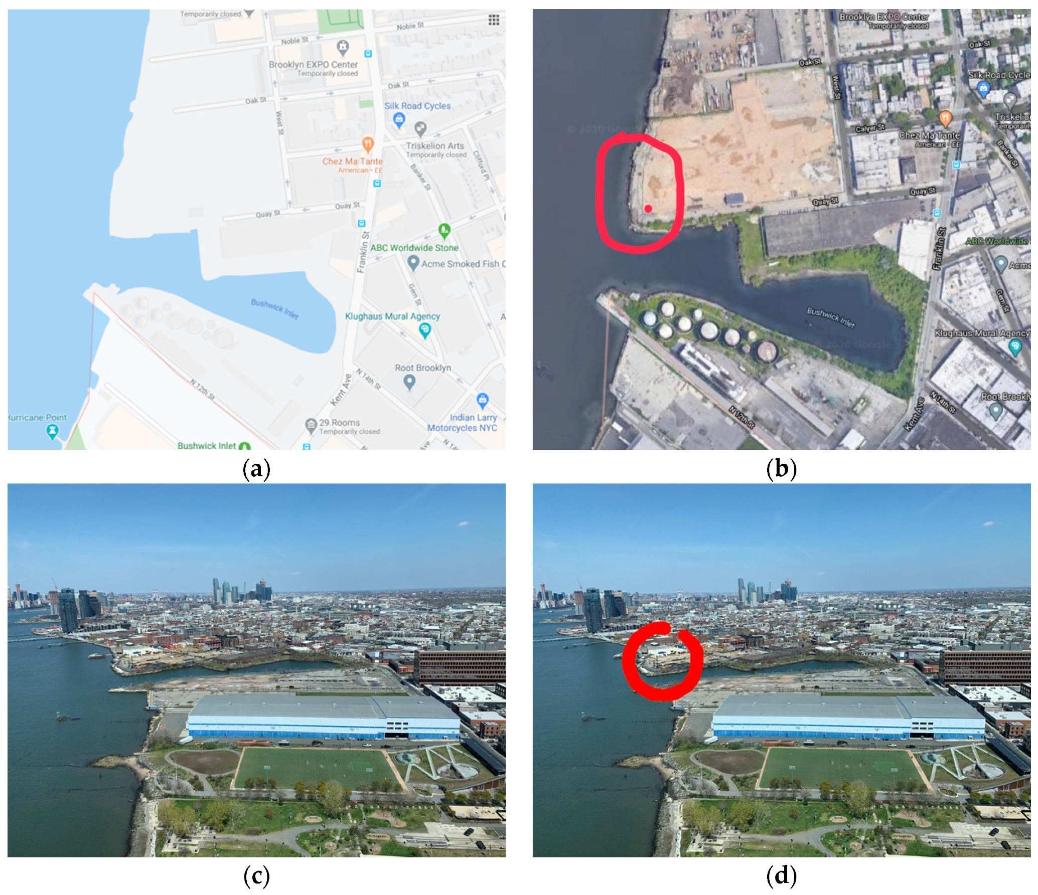
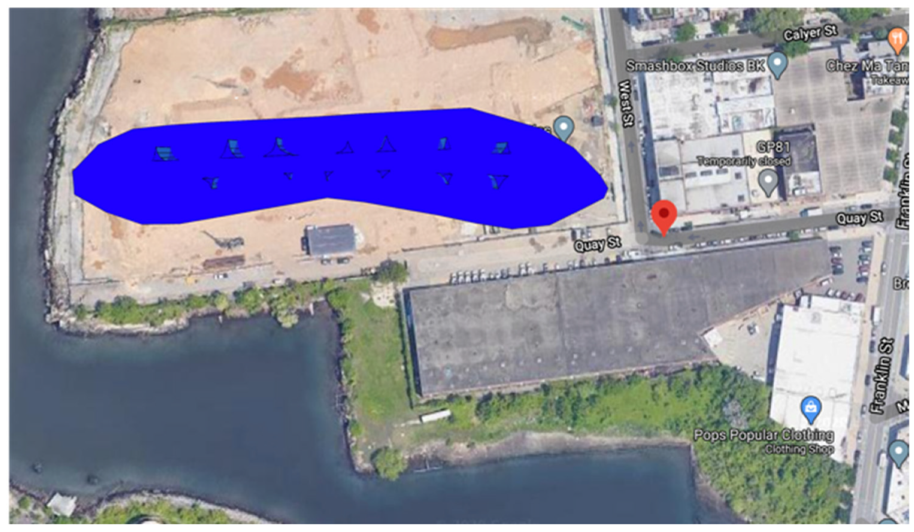
In response to the general requirements of the brief, the design was developed for a comprehensive achievement of sustainability.

2.1. The Site

The choice of the site was left to the competition teems to decide, within the five boroughs of New York City. The following considerations were made for this choice:
  • That the site should be near the water edge in order to facilitate the use of a water-source heat pump;
  • That the site should be unobstructed from the south facing side;
  • The site should receive reflected solar radiation from the water surface;
  • The site should not require demolition of any existing buildings.
After a detailed search of the New York City map, a site that meets the above criteria was found in at the bank of East River, in Quay St, Brooklyn, NY 11222, USA (Figure 1).

2.2. Carbon Neutrality/Energy Efficiency

The aim was to achieve both embodied and operational carbon neutrality. For the purpose of achieving negative embodied carbon, hemp-lime bio-composite material was chosen. As reported by Bevan and Woolley that material contains −108 kgCO2/m3 [18] (p. 81). The overall amount of embodied CO2 will be calculated when all constructions and geometry are finalized. Negative operational carbon will be achieved using methods already elaborated by Jankovic in previous studies [2].

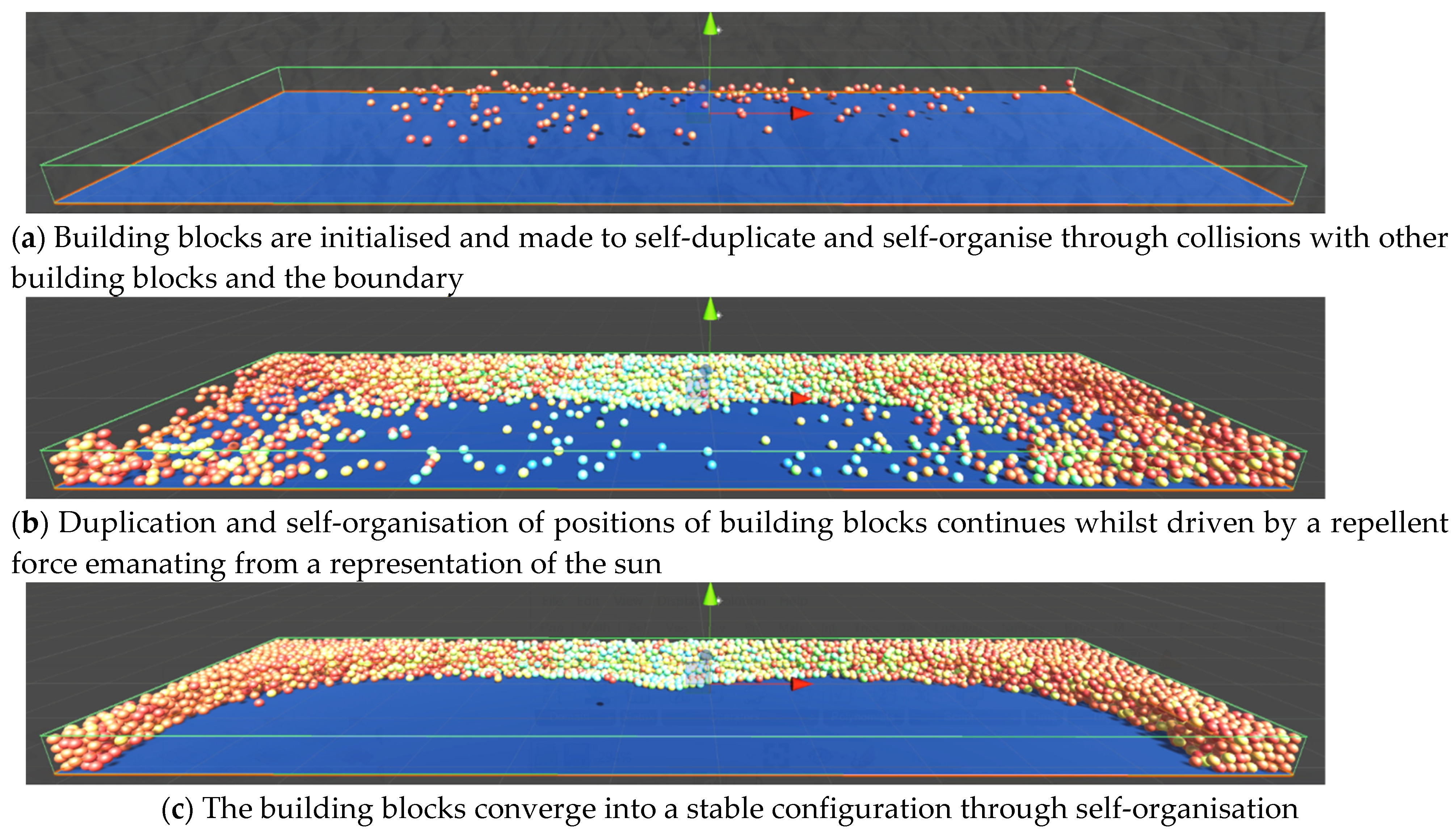
2.3. Experimental Approaches

The design was created in several steps, using a sequence of design tools and their interoperability. In order to find the optimum workflow, a number of methods were initially tested. Firstly, a genetic algorithm method was employed to optimize a generic building envelope given some initial dimensional constraints (Figure 2).
This method employed a combination of basic Grasshopper scripting to generate an initial mesh (to describe the building envelope) that is controllable through a number of variables and a solar radiation evaluation model based on Ladybug for Grasshopper [19]. The optimized values for the total radiation calculated in kW/h are then used in the fitness function of the evolutionary solver Galapagos [20], along with the mesh parameters used as genomes. This method allowed us to modify the envelope of the building based on optimum solar radiation values. The results of these initial tests were kept as a possible option, later compared and outperformed by the shallow plan option described later in this section.
Secondly, several methods were tested to cluster points in a generic floor plan based on numerical attributes (i.e., radiance values). Radiance values were assigned to each point in a regular grid within the plan outline and different machine learning models were tested to achieve the best prediction. The method that resulted in a more promising result has been the Gaussian Mixture [21]. The points inside the plan outline were used as an input and pre-set the number of clusters wanted. The Gaussian mixture algorithm provided the likelihood and probability that any given point was assigned to a certain cluster, as well as the overall prediction (expressed as an integer). As this method allowed determining the number of desired clusters in advance, a possible number of groups was tested reflecting the number of apartments needed as per brief. A convex hull method [22] was used to generate a polyline around the bound of each cluster. Figure 3 illustrates the generation of the hulls (Figure 3a) around each cluster (Figure 3b).
After several attempt at calibrating the algorithm in such a way to obtain usable clusters (and therefore outlines) for the apartments, it was decided to use alternative methods.
Thirdly, several methods were explored to help sub-diving the building envelope in order to generate a panelling for the façade with a window wall ratio (WWR) = 0.2. This has been achieved by working with several sub-division methods directly in Grasshopper, using surface subdivision and calibrating the domains for each segments of the façade. Several methods built in Lunchbox [23] were also tested as shown in Figure 4a, and eventually hexagonal apertures (Figure 4b,c) were chosen.
Although the result illustrated in Figure 4c looked promising, it has not been possible to import accurately the geometry generated in Grasshopper to EOS. It was therefore decided to reproduce a similar sub-division directly on EOS.
After these initial attempts, a more performing workflow was devised, which allowed to obtain more encouraging results.
First, the optimum form for solar exposure was developed using self-organisation of building blocks, constrained in the depth to achieve a shallow plan depth of not more than 6 m from windows. The building blocks were first initiated randomly (Figure 5a), and were made to multiply so that each building block would be copied into two, analogously to biological cell division, whilst being exposed to a repellent gravitational force emanating from a representation of the sun (Figure 5b) within Unity Game Development Platform [24]. That led to a creation of a concave south-facing form (Figure 5c), where the colour of building blocks goes towards green when closer to the representation of the sun and towards red when further away from the representation of the sun.
The (x,y) coordinates of the building blocks (Figure 6) were extracted from the 3D form from Figure 5c and transferred into Rhinoceros 3D [25] to create an outline of a prototype floor (Figure 7a).
This was subsequently transferred into the IES Virtual Environment [26], where the building envelope was finalised to standard 7.5 m wide by 3 m high exterior wall panels, with diamond shaped openable glazing representing 0.2 window to wall ratio. RadianceIES [26] was subsequently used to create an illuminance plan image of a typical floor (Figure 7b). The Radiance image was then transferred into Grasshopper [27], in which the image was colour-sampled and RGB values extracted for each point of the 1m grid (Figure 7c). Over 2700 values were obtained which were separated into intervals. This allowed identifying the points in the plan with the highest radiance value (Figure 7e), with culling points falling outside of the floor plan outline (Figure 7d). The selected points indicate the areas of the plan where the exposure to natural daylight in residential and retail areas could be maximised (Figure 7e). In order to translate these areas into habitable spaces (apartments, rooms, shops, etc.), a 2D metaball isosurface method by threshold was used. This method is based on the Marching Cubes algorithm [29] adapted by Rutten [30] in order to better control the curve falloff. More generally, metaballs are n-dimensional surfaces that can be fluidly merged based on a set proximity value. Their graphical representation was firstly developed by Blinn [31] through an algorithm that “was created to model electron density maps of molecular structures, but it can be used for other artistically interesting shapes” [31]. The metaball is generated by calculating the sphere pf influence around a given central point. In Blinn’s example, which the influence of the central point on the surrounding space is:
b ( a r )
where b is the height, a the standard deviation of a Gaussian bump, and r is the distance of the central point to any point around it.
In a more general usage, a metaball can be defined as:
f ( x , y , z ) = R 2 ( x a ) 2 + ( y b ) 2 + ( z c ) 2
where (x,y,z) are the coordinates of the point evaluated within the influence area, R is the radius of influence of the metaball and (a,b,c) is the centre of the metaball [28].
The threshold values were set out in order to obtain clusters where boundaries were not intersecting (Figure 4g). The clustering was then optimised, finally obtaining the layout for each apartment in residential floors, shops and the other required areas (Figure 7h,i).
The advantages to the building occupants are the shallow plan, the emergence of vertical ventilation stacks/light wells, resulting in maximized daylight and natural ventilation.
These layouts were transferred back to IES Virtual Environment [26] for energy and carbon emission simulations. This led to the final specification of the construction types. The construction based on hemp lime bio-composite material (hempcrete) was specified within a steel frame to facilitate multi-story construction. The main construction types were as follows:
  • External walls: 15 mm line sand render; 300 mm hempcrete; 15 mm lime sand render; U-value = 0.21 W/m2K;
  • Internal walls: 15 mm lime sand render; 300 mm hempcrete; 15 mm lime sand render
The thickness of external walls was chosen to provide a balance between thickness and U-value, consistent with experience from projects by Eberlin and Jankovic [32] and by Leskard [33]. The thickness of internal walls was gradually increased from 100 to 300 mm in order to achieve negative embodied emissions.
A subsequent transfer from IES Virtual Environment [26] into DesignBuilder [34], using gbXML [35], enabled the calculation of embodied carbon within DesignBuilder. That produced the final results, including energy consumption, operational carbon emissions and embodied carbon emissions in the building materials.

2.4. Materials Sustainability

As hempcrete is nature-based material [18], there will be potential for recycling at the end of the lifetime of the building. Although other materials may be suitable for this purpose, the choice of hempcrete was based on its well documented properties [18], on the authors’ monitoring experiences [32], and design experience [33] of this material.

2.5. Disaster Management and Durability

As hempcrete material reduces internal temperature and relative humidity fluctuations, reported in [18,32,36,37], the future climate extremes will be dampened by the building and will provide a climate refuge to the building occupants.

2.6. Indoor Environmental Quality

The use of hempcrete as the main construction material, previously used by a team member on design of a museum artefacts storage facility [33], provides thermally stable and uniform environment. Shallow plan depth, combined with vertical ventilation stacks/light wells, provide natural daylight and natural ventilation. Electrical lights are operated on the basis of occupancy and daylight sensitive dimming/daylight following using internal daylight sensors throughout the building. Glare is eliminated by passive thermochromic film on the triple glazing windows. The chilled/heated beams in combination with a reversible water source heat pump provide consistent temperature in response to changing conditions, allowing occupants to be comfortable and productive.

3. Results

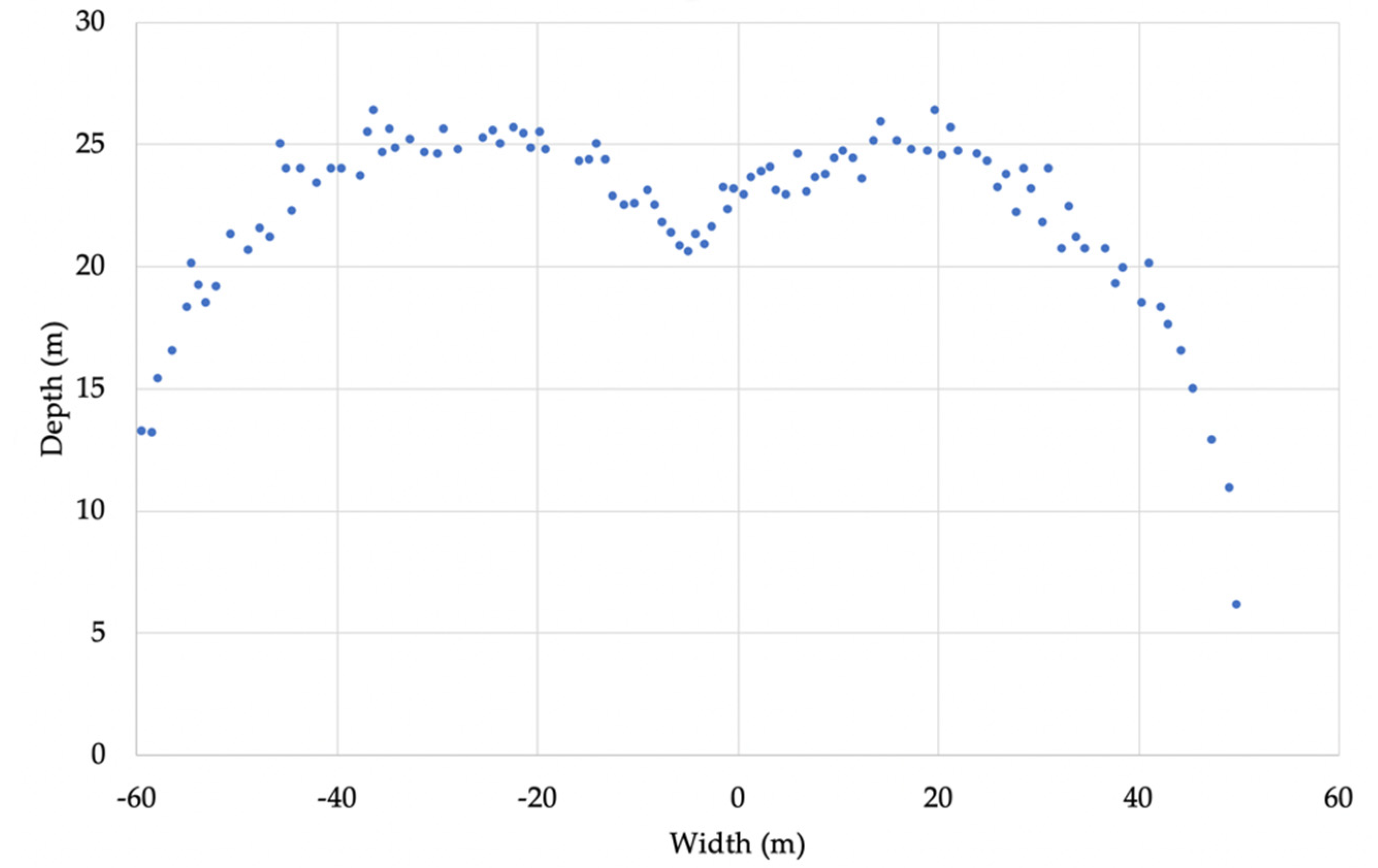
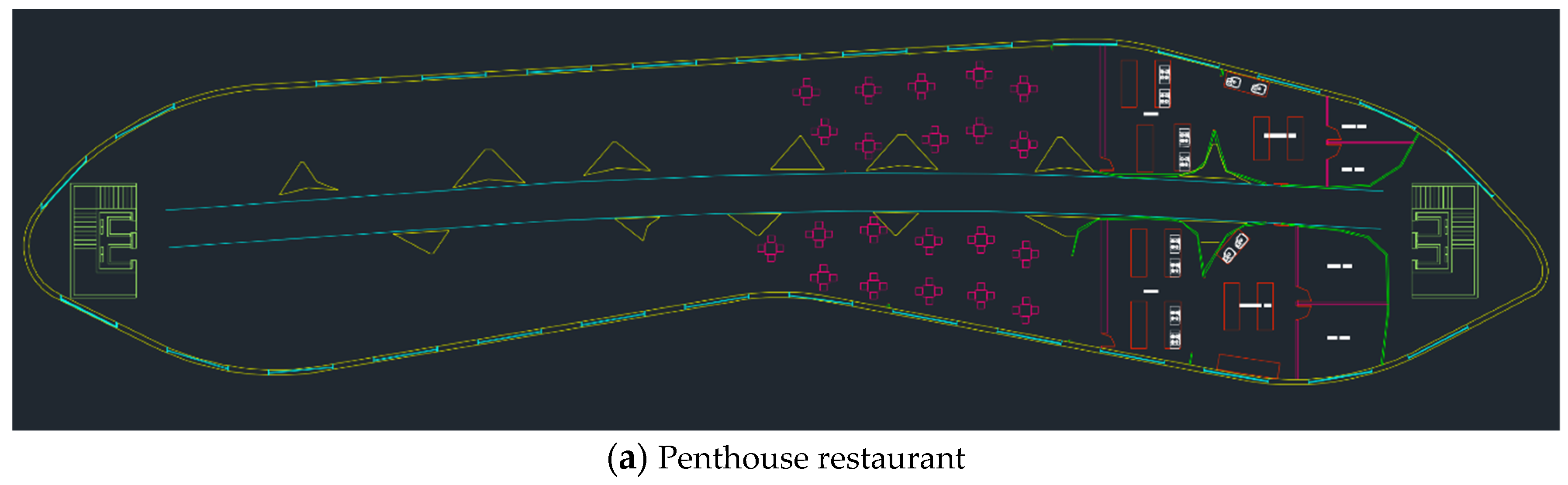
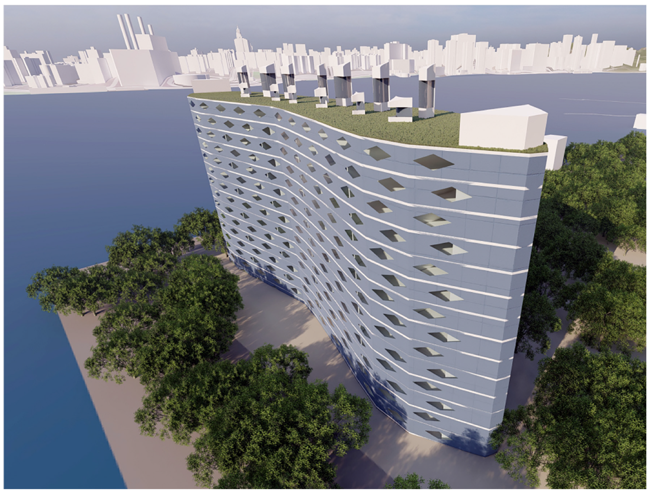
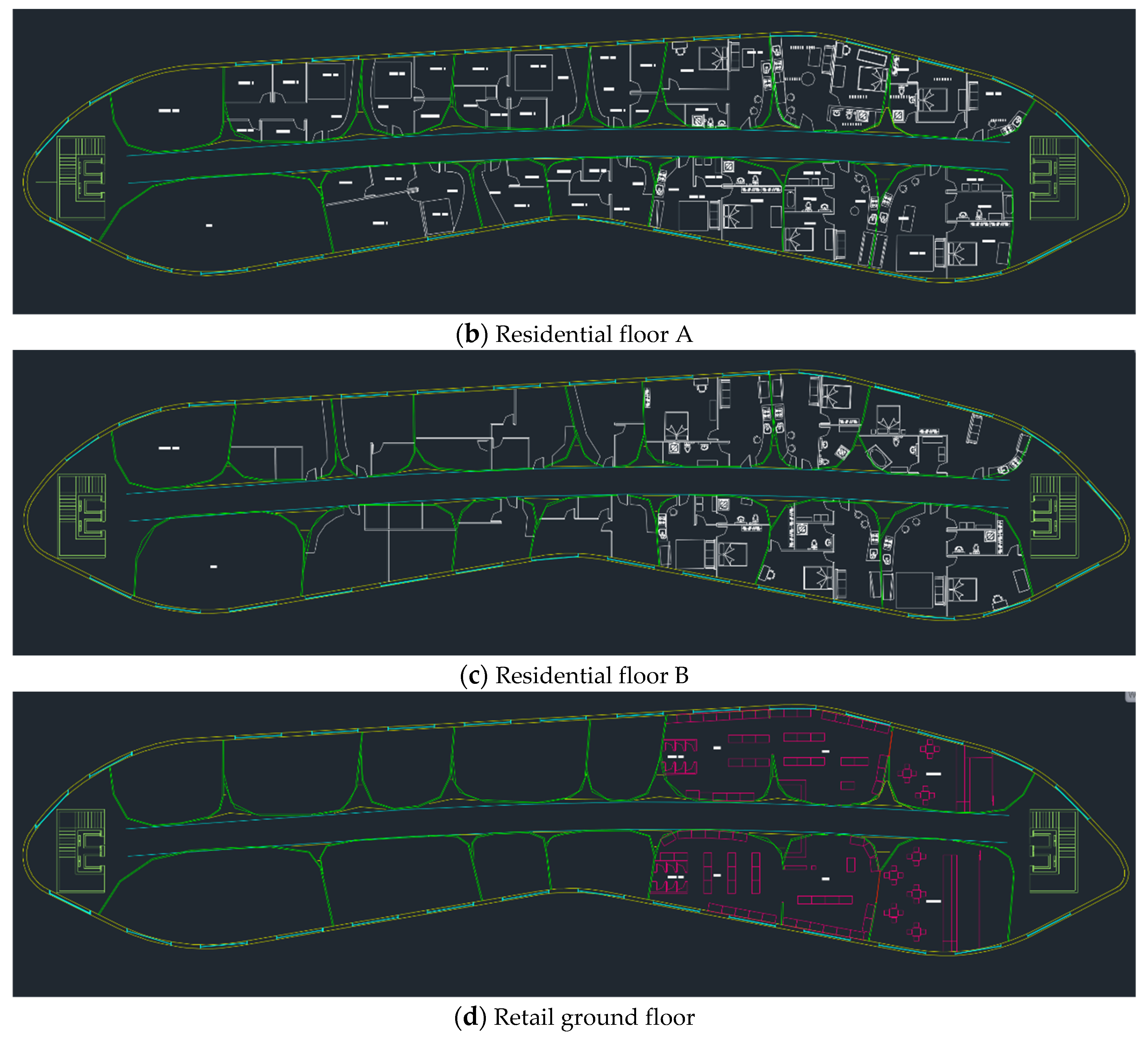
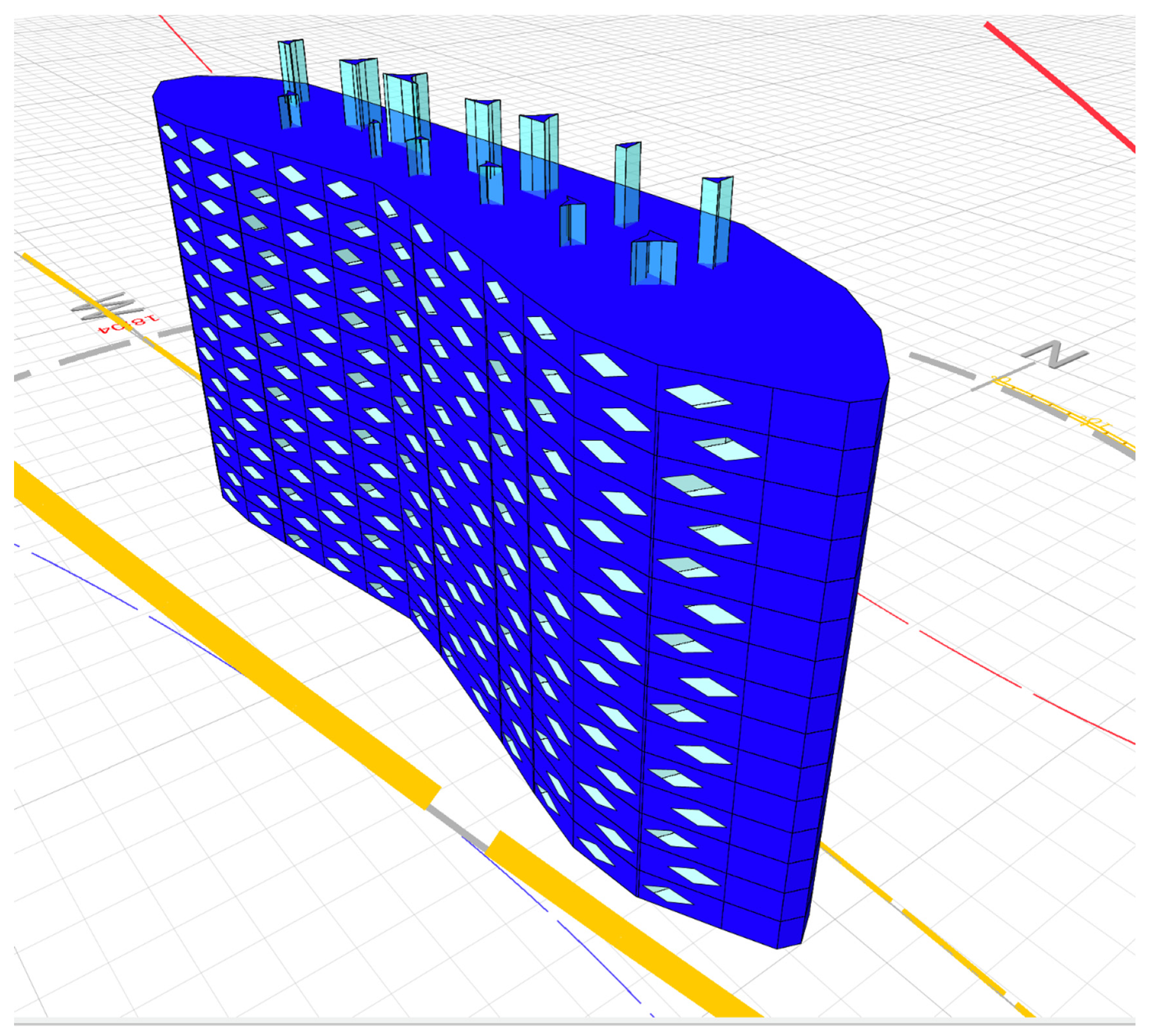
3.1. Building Geometry

The final geometry developed by this process is shown in Figure 8. The grey façade represents the Cadmium Telluride (CdTe) photovoltaic array that covers 90% of the opaque surface area of the façade. The building envelope consists of standard 7.5 m wide by 3 m high exterior wall panels, with diamond shaped openable glazing representing 0.2 window to wall ratio.
The organic shapes in the core of the floor plate (Figure 7h) create passive ventilation stacks/light wells that can be seen above the roof level in Figure 8, and extend all the way to the ground floor, thus providing natural ventilation and natural daylight. The tops of passive stacks are glazed and from the south side with dark internal surfaces opposite the glazing, in order to increase solar absorption on top of the stacks and, thus, increase the air buoyancy to drive the stack ventilation. The building outline superimposed on the site satellite image is shown in Figure 9.

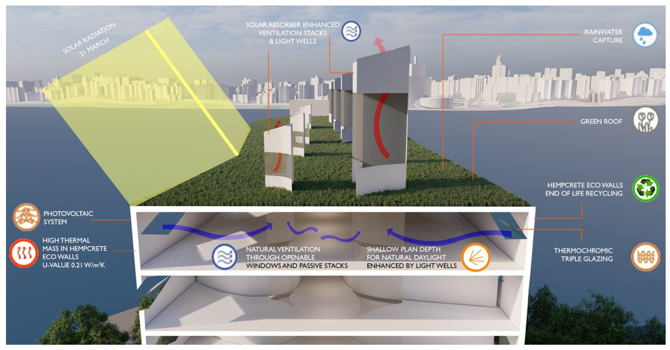
3.2. Environmental Design

Environmental design of the BioZero building is shown in Figure 10 and floor plans are shown in Figure 11.
A shallow plan depth that maximises natural daylight and natural ventilation is the basis for the BioZero design, and evolved, as introduced in Section 2. Concave south-facing façade ensures maximum solar capture. Window to wall ratio of 0.2 reduces excessive solar gains in summer and heat losses in winter. Inner light wells/ventilation stacks in combination with external glazing ensure that natural daylight and natural ventilation are maximized. Daylight sensitive dimming of LED electrical lights (daylight following) is specified for reduced energy consumption. Hemp-lime bio-composite material for external/internal walls smooths out temperature and relative humidity fluctuations and achieves negative embodied carbon. Reversible water source heat pump with heated/chilled beams is specified and uses water from East River as energy source. Cadmium Telluride (CdTe) photovoltaic array is specified, covering 90% of the opaque surface of the south-facing façade and represents 3367 m2 of on the south-facing surface. Green roof with water capture was specified to reduce temperature fluctuations on the top floor, and to restore the ground footprint lost to the construction of this building, whilst harvesting water for toilets flushing.

3.3. Energy Efficiency Measures

The rationale for the design was to achieve maximum exposure to daylight. This created organic shapes and defined light wells/ventilation stacks as result. The main energy efficiency measures are to minimize the use of electrical light and mechanical ventilation, while providing the occupants with a comfortable and productive environment.
The design of these measures required considerable iteration and interoperability of different software tools, as detailed in Section 2.

3.4. Incorporating WELL Measures

Although other standards, such as LEED [38], focus on environmental design solutions that contribute to health of building occupants, WELL is a building standard that is entirely predicated on multiple dimensions of human health [39], and was mandatory in the ASHRAE LowDown Showdown Modelling Competition where this design emerged. It considers human health in buildings using the following concepts: Air, Water, Nourishment, Light, Movement, Thermal Comfort, Sound, Materials, and Mind. Each concept has a number of preconditions and a number of optimisations that can be implemented in building design. In BioZero design Air, Light, and Thermal Comfort WELL concepts were implemented. This section outlines how this was done, making references to individual WELL numbering [39].
  • AIR
    • WELL A06 Enhanced Ventilation:
      • All of A06 was implemented as a formula in simulation software.
    • Part 1—increase outdoor air supply: outdoor air supply is increased to 5 ACH when internal air temperature is greater than 24 °C and internal air temperature is greater than outdoor air temperature.
    • Part 2—implement demand controlled ventilation: outdoor air supply is increased to 5 ACH when CO2 levels reach 600 ppm.
    • WELL A07 Operable Windows:
      • All of A07 is implemented as a special measure in design.
    • Part 1—Provide Operable Windows:
      • a.1 Operable windows are provided to all occupied spaces except to circulation, therefore, to 92% of all occupied spaces, exceeding the 75% WELL requirement.
      • a.2 The openable window area is 6% of the net occupied floor area, exceeding the 4% WELL requirement.
  • LIGHT
    • WELL L03 Circadian Lighting Design:
      • Daylight-sensitive dimming control is implemented in all spaces to ensure ‘daylight following’ on a proportional range between 0 and 300 lux, so that the total daylight and electrical light is 300 lux during occupied hours; implemented as a formula in simulation software.
    • WELL L04 Glare Control:
      • Part 1—control solar glare: external glazing is fitted with passive thermochromic film to control solar glare above 400 lux; implemented in simulation software.
    • WELL L05 Enhanced Daylight Access:
      • All of L05 was implemented as a special measure in design.
        • Part 1—implement enhanced daylight plan:
          a.1 All spaces (100%) are within 7.5 m of transparent envelope glazing or light wells, exceeding the 70% WELL requirement.
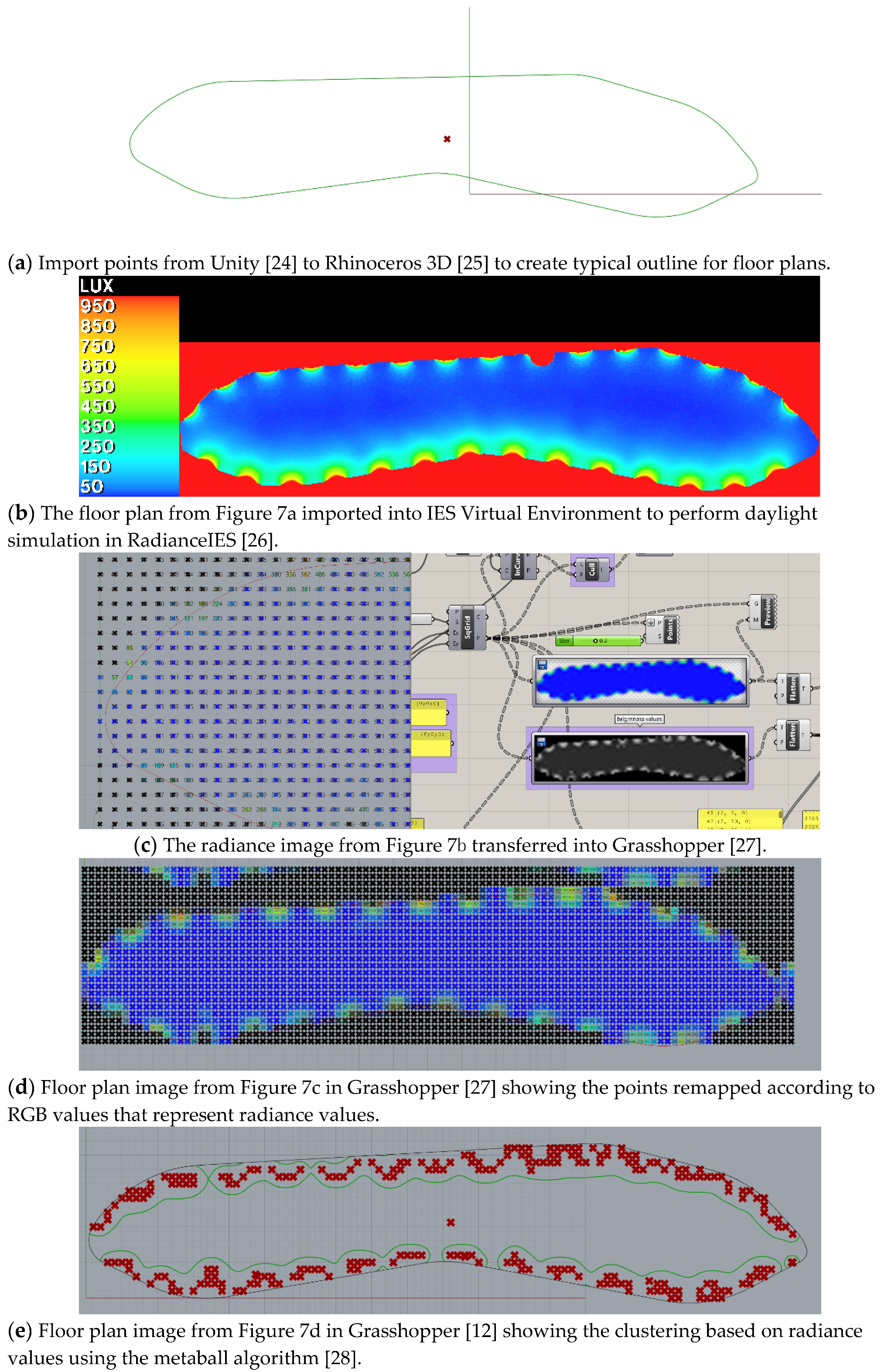
        • Part 2—implement enhanced daylight simulation: radiance simulation is carried out at the outset to determine the plan depth and location of partition walls.
        • Part 3—Ensure Views—Transparent envelope glazing provides access to views to 100% of regular building occupants, exceeding 50% WELL requirement.
  • THERMAL COMFORT
    • WELL T02 Enhanced Thermal Performance:
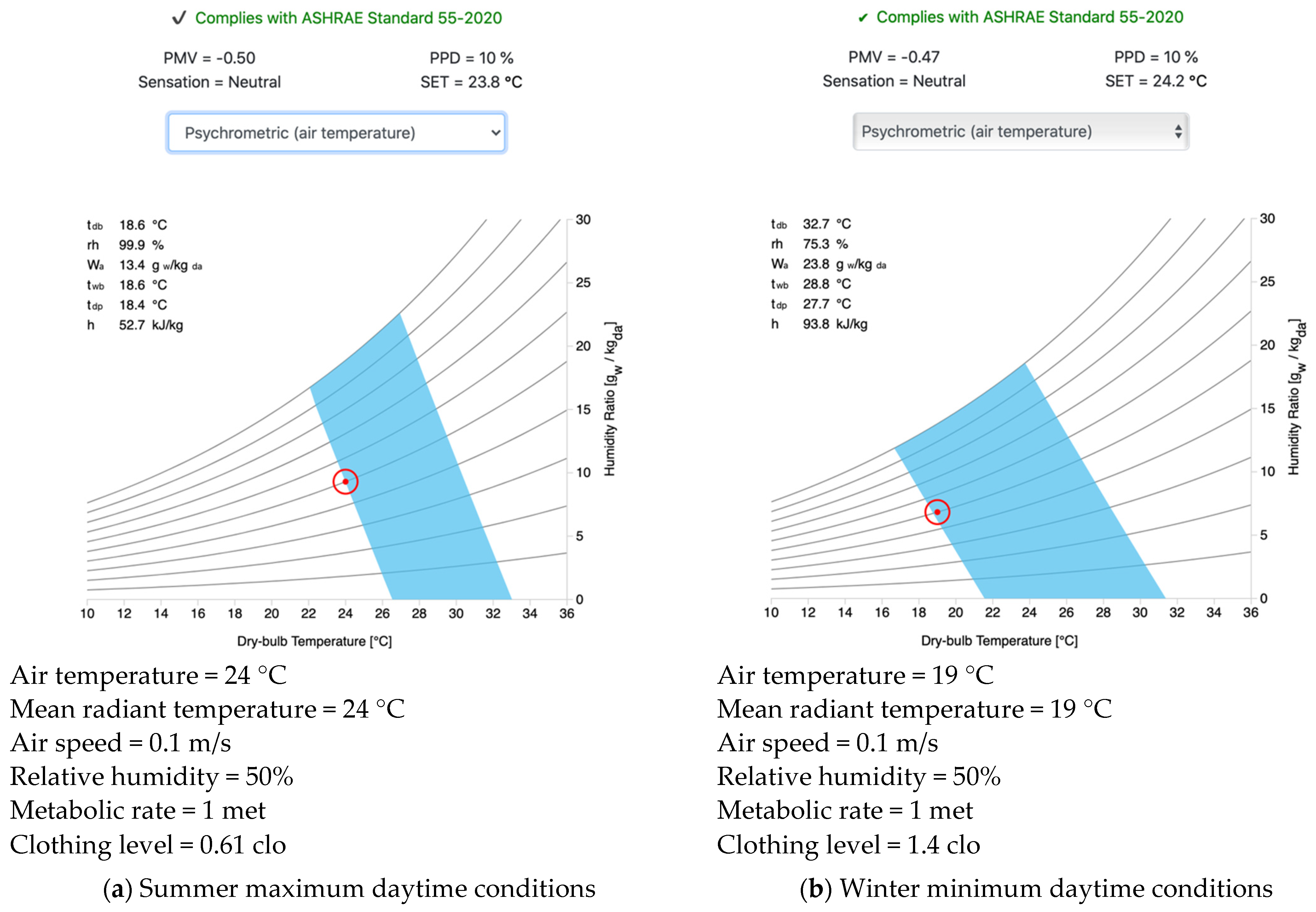
      • Part 1—enhance thermal environment: the design combines mechanical ventilation and natural ventilation and achieves PPD ≤ 10% and 90% acceptability limit as per ASHRAE 55, as per the WELL requirement. This is the consequence of special measures in design, and of the settings in the simulation software.
    • WELL T05 Radiant Thermal Comfort:
      • Part 1—implement radiant system: the design is serviced by a hydronic heating and cooling system, as per the WELL requirement. This is implemented as settings in the simulation software.

3.5. Embodied Carbon Emissions

The construction is based on hemp-lime bio-composite material (hempcrete) within steel frame: external walls: 15 mm line sand render; 300 mm hempcrete; 15 mm lime sand render; U-value = 0.21 W/m2K; internal walls: 15 mm lime sand render; 300 mm hempcrete; 15 mm lime sand render.
Previous research [37] and design [33] experience shows that this material considerably smooths out fluctuations of internal temperature and relative humidity.
Due to sequestration of CO2 in the hemp plant during its growth, the BioZero building achieves negative embodied emissions of −227,267 kgCO2. This was calculated from the simulation model in DesignBuilder [34], using independent published evidence of embodied CO2 [18] (p. 81). Calculation details are shown in Table 1.
As result, the benefits to occupants are uniform internal environment and climate refuge against future climate extreme negative embodied emissions. The benefits to the City of New York are the negative embodied carbon emissions and the opportunity to build envelope material recycling at the end of the building lifetime.

3.6. Operational Carbon Emissions

Energy performance and operational emissions were modelled in IES Virtual Environment [26] (Figure 12). The shallow plan depth developed based on the process described in Section 2, facilitated the introduction of a light dimming control function using the daylight sensor, and a formula that proportionally complements daylight with electrical lighting. Internal conditions in summer were allowed to float freely between 19 °C and 22 °C. Free cooling was activated through window opening between 22 °C and 24 °C, if external air temperature was lower than internal air temperature. At 24 °C, active cooling was switched on. Night-time setback temperature was set to 16 °C in winter and to 27 °C in summer. Window opening was also triggered by internal CO2 concentration above 600 ppm. The simulation model geometry is shown in Figure 11.
Building carbon emissions performance was investigated for three different systems, in order to choose the system that results in the lowest emissions. These systems consisted of a water source heat pump, biogas heating combined with electric cooling, and biogas heating combined with absorption chiller cooling. The results are shown in Table 1. The first system was as originally intended, due to the proximity of water suitable for a water source heat pump. However, as can be seen from Table 1, this system generates a significant amount of carbon emissions that could not be eliminated by the PV system. In search of a better system, biogas heating combined with electric cooling was investigated. However, that system too generated positive carbon emissions, albeit significantly reduced. The third system investigated, biogas heating combined with absorption chiller cooling, generated significant negative carbon emissions, as shown in Table 1, and this was the system adopted for the BioZero building.
Whilst the BioZero team members routinely carry out performance evaluation of building designs using future weather data, this was in fact a mandatory requirement in the ASHRAE LowDown Showdown Modelling Competition, where this design emerged. The future weather data, supplied by competition organisers for 2030 and 2050, was based on the HadCM3 coupled climate model used for climate prediction [40], and was generated using the CCWorldWeatherGen tool [41].
A further investigation of carbon emissions for the adopted system followed, for future climate years, as shown in Table 2. As can be seen from that table, the building will achieve operational carbon neutrality to the year 2050.
Therefore, as calculated by the IES Virtual Environment model [26], and shown in Table 2, the building will achieve operational carbon neutrality to 2050, due to energy efficiency combined with a PV array on the south-facing façade.

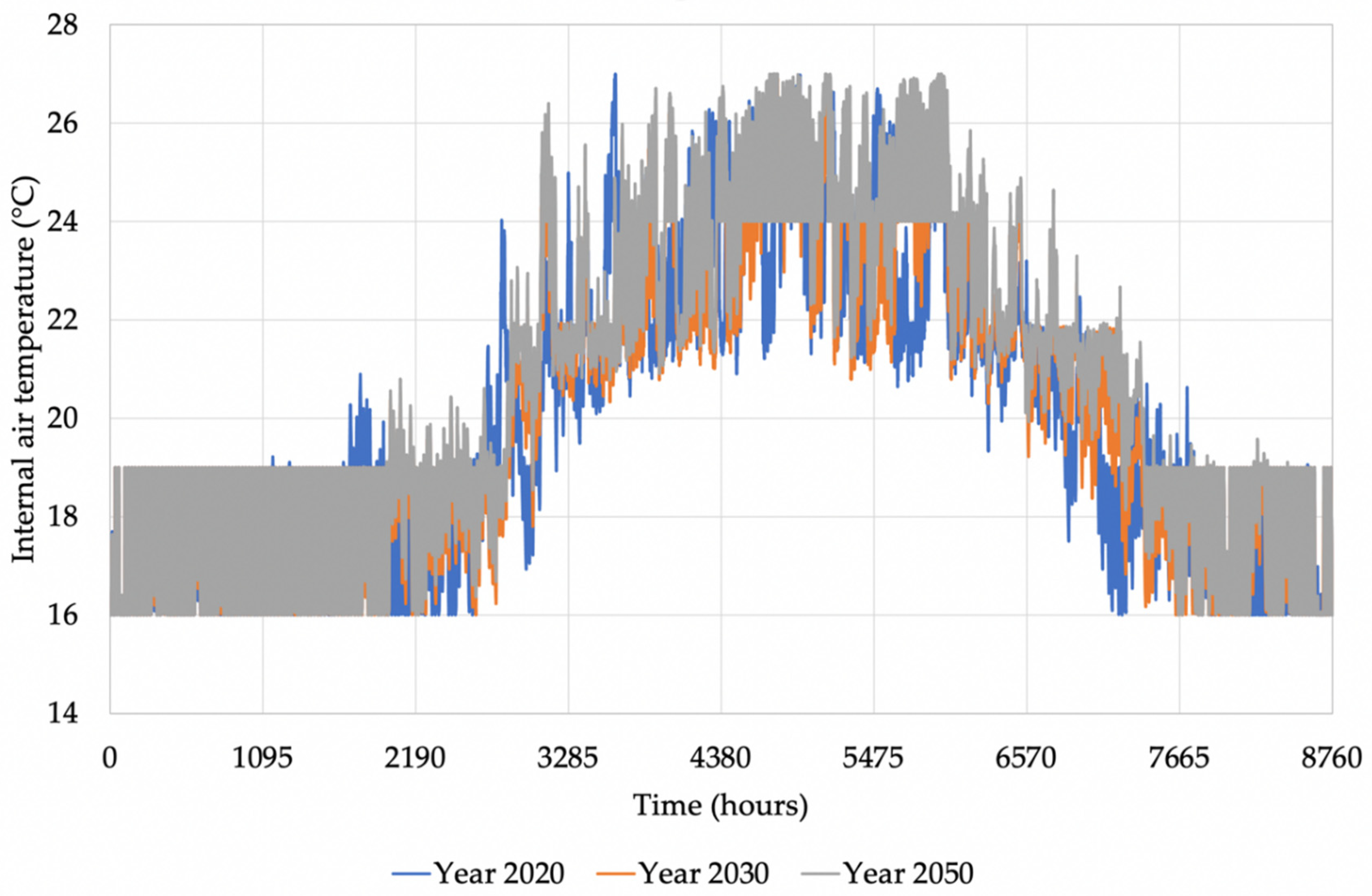
3.7. Thermal Comfort

As zero carbon design cannot be achieved without ensuring satisfactory thermal comfort [2], internal room air temperatures were analysed for a typical south facing apartment. Hourly room air temperatures are shown in Figure 13 and cumulative frequency of occurrence of temperatures is shown in Figure 14. In these figures, daytime set temperatures go from 19 °C in the winter to 24 °C in the summer, while the night setback temperature is 16 °C in the winter and 27 °C in the summer.
The daytime temperature range was subsequently run through ASHRAE Standard 55-2000 [42] and the results are shown in Figure 15. As can be seen from this figure, thermal comfort is achieved within 10% predictive percentage of dissatisfied (PPD), in both the summer and winter. A critical adaptation factor between the seasons is the clothing level, which shows that occupants have a part to play in ensuring zero carbon performance, thus adapting the clothing between 0.7 clo in the summer and 1.4 clo in the winter. This can be achieved by different clothing ensembles, as detailed in [42].

3.8. Energy Consumption

Summary of energy consumption per use type is shown in Table 3. As can be seen from this table, an increased energy consumption is expected in future climate years. This is mainly due to increased cooling loads expected in future climates.
Energy consumption figures per floor area in this table enable a comparison to be made with the Passivhaus standard [43]. According to this standard, space heating demand must be ≤15 kWh/m2 per annum space cooling demand must be ≤15 kWh/m2 per annum. As can be seen from Table 3, space heating demand in BioZero building is slightly higher than this, namely 17.31 kWh/m2 per annum, and it gets close to the Passivhaus standard in the year 2050, namely 15.88 kWh/m2 per annum. Space cooling demand in the BioZero building is considerably better, from 1.84 kWh/m2 per annum in 2020 to 4.08 kWh/m2 per annum in 2050.
Summary of energy consumption per use type is shown in Table 4. Primary energy in this table was calculated using primary energy factors from [44]. This now enables a further comparison with the Passivhaus standard [43], where primary energy demand must be ≤120 kWh/m2 per annum. As can be seen from Table 4, primary energy demand is less than 45 kWh/m2; therefore, significantly better than the Passivhaus standard. The corresponding energy consumption per energy source type is shown in Table 5.

4. Discussion

As illustrated in the introduction, there is a body of work in the fields of zero carbon buildings, net zero energy buildings, and nearly zero-energy buildings. However, these works primarily focused on case studies of specific projects or specific aspects of building performance, rather than on fundamental principles and integration of these principles into holistic designs. Hence, there is a general lack in the holistic ‘how to’ studies in the fields of zero carbon buildings, net zero energy buildings, and nearly zero-energy buildings. As a step forward from the ‘how to’ approach introduced by ‘Designing Zero Carbon Buildings Using Dynamic Simulation Methods’ [2], this article introduces a new method that combines fundamental principles with the use of design tools, creating a new workflow for making the achievement of net zero design easier. Whilst all or other studies focus on operational emissions only, this article combines operational with embodied emissions to achieve truly holistic net zero design.
The structured approach for designing a net zero emissions building introduced in this article showed that putting sustainability principles in place from early design considerations, such as good thermal insulation of the building envelope, shallow plan depth that maximises natural daylighting and natural ventilation, free cooling, and electrical lighting control, lends itself for successful development of operational zero carbon design. However, zero carbon design is not automatically achieved in this way, and it requires detailed analysis of systems, schedules, and controls in order to achieve it.
Operational carbon emissions are only a part of the strategy, as embodied emissions with conventional materials can add significant carbon balance to the building. In the case of BioZero design, the research team’s experience with photosynthetic materials, such as hemp-lime bio-composite [32,36,37], was used to achieve negative embodied emissions.
In this project, the team was particularly interested in the general workflow and in reflecting on how to engage with colleagues with different expertise, working as an interdisciplinary group. The design process was non-linear: starting from conception, converting into shapes, back into simulation, and eventually followed by visualisation. The control of the various stages of development passed on from one team member to another and one design/visualisation tool to another. From a purely speculative perspective, the emphasis of this project is on the workflow, rather than the building designed. A workflow that should work regardless of the building location and type was developed. The methods involved should work independently of these aspects.
In using multiple tools, issues about data transfer between building simulation software and 3D modelling parametric tools were experienced. Significant time was spent on testing and experimenting with data exchange capabilities between different platforms. For example, Green Building XML (gbXML) [35] for exchange of data was relied upon, but while exporting from one application to another, either datapoints (and surfaces) or found difficulties in the exporting itself were lost. To improve the proposed workflow, a better capability for information exchange is needed, as different tools did not allow for data exchange seamlessly.

5. Conclusions

Building designs are typically top–down and developed in series between architects and engineers, whereby an architect develops a concept, explores (often) a small number of options, develops the form and layouts, and passes the most favourable option to an engineer to develop the way the building will work.
In contrast to this linear approach, BioZero was developed from the bottom–up, in an architect–engineer collaboration, and evolved from sustainability principles, creating a nature-inspired net zero design. By using the nature-inspired approach to form creation, which resulted in a shallow plan depth that facilitated natural ventilation and natural daylight, the achievement of a net zero design was facilitated by good thermal insulation, use of free cooling with external air to minimize active comfort cooling, daylight control that complemented natural daylighting, and detailed building performance simulations that determined the choice of heating, cooling, and renewable energy systems.
Based on the experience in this study, the authors hold that significant development of interoperability between design tools is required, as the current poor interoperability caused extensive time to be spent on transferring information between the design tools.
The team believes that this non-linear approach to building design—based on the evidence found in this study—offers great potential and could be a real game changer. Hybrid and non-linear approaches to design are increasingly promising in helping the architecture, engineering, and construction (AEC) industry meet the sustainable targets as set out by national and international organizations (for example, the United Nations Sustainable Development Goals).
This approach has resulted in a building design that achieves negative embodied and operational carbon emissions, as well as healthy, internal conditions for occupants. The stable temperature and relative humidity characteristics of the hempcrete material are to ensure climate refuge to building occupants against increased temperatures caused by climate change.
Future design work will use the developed workflow, the methods, and the tools, focusing on the interoperability of the tools that worked successfully. The team will also work with design and simulation tool developers, to help them understand the needs of designers for better interoperability of design tools.

Author Contributions

Conceptualization, L.J. and S.C.; methodology, L.J. and S.C.; investigation, L.J. and S.C.; writing—original draft preparation, L.J.; writing—review and editing, S.C.; project administration, L.J. All authors have read and agreed to the published version of the manuscript.

Funding

This research received no external funding. Generous support was received from the School of Creative Arts of the University of Hertfordshire in respect of the preparation of material for this article.

Acknowledgments

A poster featuring this project was submitted to the 2020 ASHRAE LowDown Showdown Modelling Competition as part of the 2020 Building Performance Analysis Conference and SimBuild. The authors wish to thank Ian Owen and Purvesh Bharadwaj from Zero Carbon Lab, School of Creative Arts, University of Hertfordshire, for the rendered images in Figure 8 and Figure 10 (I.O.), and for the floor plans in Figure 11 (P.B.). They also wish to thank Craig Jackson, resident of Brooklyn, for the site photo in Figure 1.

Conflicts of Interest

The authors declare no conflict of interest.

References

  1. Jankovic, L. An Emergence-Based Approach to Designing. Des. J. 2012, 15, 325–346. [Google Scholar] [CrossRef]
  2. Jankovic, L. Designing Zero Carbon Buildings Using Dynamic Simulation Methods, 2nd ed.; Routledge: London, UK, 2017; ISBN 978-1-138-65831-8. [Google Scholar]
  3. Trofimova, P.; Cheshmehzangi, A.; Deng, W.; Hancock, C. Post-Occupancy Evaluation of Indoor Air Quality and Thermal Performance in a Zero Carbon Building. Sustainability 2021, 13, 667. [Google Scholar] [CrossRef]
  4. Li, H.; Wang, S.; Cheung, H. Sensitivity Analysis of Design Parameters and Optimal Design for Zero/Low Energy Buildings in Subtropical Regions. Appl. Energy 2018, 228, 1280–1291. [Google Scholar] [CrossRef]
  5. Rey-Hernández, J.M.; Yousif, C.; Gatt, D.; Velasco-Gómez, E.; San José-Alonso, J.; Rey-Martínez, F.J. Modelling the Long-Term Effect of Climate Change on a Zero Energy and Carbon Dioxide Building through Energy Efficiency and Renewables. Energy Build. 2018, 174, 85–96. [Google Scholar] [CrossRef]
  6. Yang, X.; Zhang, S.; Xu, W. Impact of Zero Energy Buildings on Medium-to-Long Term Building Energy Consumption in China. Energy Policy 2019, 129, 574–586. [Google Scholar] [CrossRef]
  7. Lizana, J.; Chacartegui, R.; Barrios-Padura, A.; Valverde, J.M. Advances in Thermal Energy Storage Materials and Their Applications towards Zero Energy Buildings: A Critical Review. Appl. Energy 2017, 203, 219–239. [Google Scholar] [CrossRef]
  8. Hollberg, A.; Genova, G.; Habert, G. Evaluation of BIM-Based LCA Results for Building Design. Autom. Constr. 2020, 109, 102972. [Google Scholar] [CrossRef]
  9. Li, B. Use of Building Energy Simulation Software in Early-Stage of Design Process; KTH Royal Institute of Technology: Stockholm, Sweden, 2017. [Google Scholar]
  10. Charles, A.; Maref, W.; Ouellet-Plamondon, C.M. Case Study of the Upgrade of an Existing Office Building for Low Energy Consumption and Low Carbon Emissions. Energy Build. 2019, 183, 151–160. [Google Scholar] [CrossRef]
  11. Kim, S.-C.; Yoon, J.-H.; Lee, R.-D. Energy Performance Assessment of a 2nd-Generation Vacuum Double Glazing Depending on Vacuum Layer Position and Building Type in South Korea. Energies 2017, 10, 1240. [Google Scholar] [CrossRef] [Green Version]
  12. Petri, I.; Kubicki, S.; Rezgui, Y.; Guerriero, A.; Li, H. Optimizing Energy Efficiency in Operating Built Environment Assets through Building Information Modeling: A Case Study. Energies 2017, 10, 1167. [Google Scholar] [CrossRef] [Green Version]
  13. Zhao, X.; Pan, W. Delivering Zero Carbon Buildings: The Role of Innovative Business Models. Procedia Eng. 2015, 118, 404–411. [Google Scholar] [CrossRef] [Green Version]
  14. Jankovic, L. Opportunities for Financing Sustainable Development Using Complementary Local Currencies. IOP Conf. Ser. Earth Environ. Sci. 2019, 297, 012023. [Google Scholar] [CrossRef]
  15. Aelenei, L.; Gonçalves, H. From Solar Building Design to Net Zero Energy Buildings: Performance Insights of an Office Building. Energy Procedia 2014, 48, 1236–1243. [Google Scholar] [CrossRef] [Green Version]
  16. Shi, F.; Wang, S.; Huang, J.; Hong, X. Design Strategies and Energy Performance of a Net-Zero Energy House Based on Natural Philosophy. J. Asian Archit. Build. Eng. 2020, 19, 1–15. [Google Scholar] [CrossRef]
  17. Wall, M. Towards Zero-Energy Buildings and Neighbourhoods—A Combination of Energy-Efficiency and Local Renewable Energy Production. Indoor Built Environ. 2017, 26, 1313–1318. [Google Scholar] [CrossRef]
  18. Bevan, R.; Woolley, T. Hemp Lime Construction: A Guide to Building with Hemp Lime Composites; IHS BRE Press: London, UK, 2008; ISBN 978-1-84806-033-3. [Google Scholar]
  19. Sadeghipour Roudsari, M.; Pak, M. Ladybug: A Parametric Environmental Plugin for Grasshopper to Help Designers Create an Environmentally-Conscious Design. In Proceedings of the BS2013, 13th Conference of International Building Performance Simulation Association, Chambéry, France, 26–28 August 2013. [Google Scholar]
  20. Rutten, D. Galapagos: On the Logic and Limitations of Generic Solvers. Arch. Des. 2013, 83, 132–135. [Google Scholar] [CrossRef]
  21. Reynolds, D. Gaussian Mixture Models. In Encyclopedia of Biometrics; Li, S.Z., Jain, A., Eds.; Springer: Boston, MA, USA, 2009; pp. 659–663. ISBN 978-0-387-73002-8. [Google Scholar]
  22. Melkman, A.A. On-Line Construction of the Convex Hull of a Simple Polyline. Inf. Process. Lett. 1987, 25, 11–12. [Google Scholar] [CrossRef]
  23. Proving Ground LunchBox. 2015. Available online: https://provingground.io/tools/lunchbox/ (accessed on 24 November 2020).
  24. Unity Technologies Unity Game Development Platform. Available online: https://unity3d.com (accessed on 3 March 2020).
  25. Simply Rhino Limited Rhino3D. Available online: https://www.rhino3d.co.uk/ (accessed on 17 November 2020).
  26. IES VE 2019. Available online: https://www.iesve.com/VE2019 (accessed on 18 March 2018).
  27. Robert McNeel & Associates Grasshopper. Available online: https://www.rhino3d.com/new-source/api/main/ (accessed on 17 November 2020).
  28. House, H.D. CP SC 881-02—Quick Introduction to Metaballs. Available online: https://people.cs.clemson.edu/~dhouse/courses/881/notes/metaballs/index.html (accessed on 17 April 2021).
  29. Lorensen, W.E.; Cline, H.E. Marching Cubes: A High Resolution 3D Surface Construction Algorithm. SIGGRAPH Comput. Graph. 1987, 21, 163–169. [Google Scholar] [CrossRef]
  30. Rutten, D. Metaball Equation 2011. Grasshopper3d.com Forum Entry. Available online: https://www.grasshopper3d.com/forum/topics/metaball-equation?overrideMobileRedirect=1 (accessed on 24 November 2020).
  31. Blinn, J.F. A Generalization of Algebraic Surface Drawing. ACM Trans. Graph. 1982, 1, 235–256. [Google Scholar] [CrossRef]
  32. Eberlin, C.; Jankovic, L. Exploring the energy performance of hemcrete in affordable housing and future implications for carbon reduction in the housing sector. In Proceedings of the Zero Carbon Buildings Today and in the Future 2014, Birmingham, UK, 11–12 September 2014. [Google Scholar]
  33. Leskard, M. A Sustainable Storage Solution for the Science Museum Group. Sci. Mus. Group J. 2020, 4. [Google Scholar] [CrossRef]
  34. DesignBuilder Software Ltd. DesignBuilder. Available online: https://designbuilder.co.uk/ (accessed on 26 March 2019).
  35. Green Building XML (gbXML) Schema, Inc. GbXML—An Industry Supported Standard for Storing and Sharing Building Properties between 3D Architectural and Engineering Analysis Software. Available online: https://www.gbxml.org/ (accessed on 22 April 2021).
  36. Bana, A.; Jankovic, L. Reducing Simulation Performance Gap from Hempcrete Buildings Using Multi Objective Optimization. In Proceedings of the Building Simulation 2019, Rome, Italy, 2–4 September 2019; pp. 425–432. [Google Scholar]
  37. Jankovic, L. Reducing Simulation Performance Gap in Hemp-Lime Buildings Using Fourier Filtering. Sustainability 2016, 8, 864. [Google Scholar] [CrossRef] [Green Version]
  38. U.S. Green Building Council LEED|Leadership in Energy & Environmental Design. Available online: http://leed.usgbc.org/leed.html (accessed on 18 June 2021).
  39. International WELL Building Institute pbc. WELL V2 Standard. Available online: https://v2.wellcertified.com/v/en/overview (accessed on 17 November 2020).
  40. The Met Office. HadCM3: Met Office Climate Prediction Model. Available online: https://www.metoffice.gov.uk/research/approach/modelling-systems/unified-model/climate-models/hadcm3 (accessed on 18 June 2021).
  41. Jentsch, M.F.; James, P.A.B.; Bourikas, L.; Bahaj, A.S. Transforming Existing Weather Data for Worldwide Locations to Enable Energy and Building Performance Simulation under Future Climates. Renew. Energy 2013, 55, 514–524. [Google Scholar] [CrossRef]
  42. Tartarini, F.; Schiavon, S.; Cheung, T.; Hoyt, T. CBE Thermal Comfort Tool: Online Tool for Thermal Comfort Calculations and Visualizations. SoftwareX 2020, 12, 100563. [Google Scholar] [CrossRef]
  43. Passivhaus Trust What Is Passivhaus? Available online: https://www.passivhaustrust.org.uk/what_is_passivhaus.php (accessed on 19 April 2021).
  44. BRE Briefing Note on Derivation of PE Factors 2019. Available online: https://www.bregroup.com/wp-content/uploads/2019/10/Briefing-note-on-derivation-of-PE-factors-V1.3-01-10-2019.pdf (accessed on 19 April 2021).
Figure 1. The site chosen on the basis of the four criteria explained in the text: (a) site map; (b) site satellite image with building location circled; (c) site aerial photograph; (d) site aerial photograph with building location circled.
Sustainability 13 07658 g001
Figure 2. Generation of the building envelope based on radiation analysis with local values.
Sustainability 13 07658 g002
Figure 3. Clustering of points based on radiance values using Gaussian mixture.
Sustainability 13 07658 g003
Figure 4. Testing of sub-division of the façade based on a WWR = 0.2.
Sustainability 13 07658 g004
Figure 5. Self-organisation of building blocks in Unity [24] resulting in a shallow concave south-facing form.
Sustainability 13 07658 g005
Figure 6. The (x,y) coordinates of the building blocks extracted from the 3D form in Figure 5.
Sustainability 13 07658 g006
Figure 7. Form creation for daylight-sensitive design.
Sustainability 13 07658 g007aSustainability 13 07658 g007b
Figure 8. The BioZero building.
Sustainability 13 07658 g008
Figure 9. The building outline superimposed on the site satellite image.
Sustainability 13 07658 g009
Figure 10. Environmental design.
Sustainability 13 07658 g010
Figure 11. BioZero building floor plans.
Sustainability 13 07658 g011aSustainability 13 07658 g011b
Figure 12. BioZero model in IES Virtual Environment [26].
Sustainability 13 07658 g012
Figure 13. Internal air temperatures in a south-facing apartment.
Sustainability 13 07658 g013
Figure 14. Cumulative frequency of occurrence of internal air temperatures in a south-facing apartment.
Sustainability 13 07658 g014
Figure 15. Testing summertime and wintertime conditions against ASHRAE Standard 55-2000. (Source: [42]).
Sustainability 13 07658 g015
Table 1. Embodied carbon emissions.
Materials Embodied Carbon and InventoryArea (m2)Equivalent CO2 (kgCO2)Mass (kg)
ECO roof material4688.218,752.8937,639.4
Hempcrete21,150.8−564,353.21,694,754.5
Steel 5% in Hempcrete 123,717.184,737.7
Timber Flooring4781.119,986.142,523.6
Lime sand render42,301.710,152.41,015,240.2
External Rendering3120.510,141.6101,415.7
Floor/Roof Screed1660.622,318.7139,491.9
Urea Formaldehyde Foam1660.62770.71443.1
MW Stone Wool (rolls)3120.510,746.99595.5
Concrete Reinforced (with 1% steel; cement free: 5% embodied carbon)16,858.752,346.43,877,510
Cast Concrete—cement free: 5% embodied carbon1660.61328.5332,123.6
Aerated Concrete Slab—cement free: 5% embodied carbon4688.27969.9468,819.7
Sub Total −284,122.18,620,557.2
Glazing Embodied Carbon and InventoryArea (m2)Equivalent CO2 (kgCO2)
Project internal glazing1056.410,247.3
Project external glazing2589.346,607.6
Local shading 0
Window shading 0
Sub Total3645.756,854.9
Building Total51,124.6−227,267.2
Table 2. Carbon emissions investigation for three different heating and cooling systems.
Water Source Heat PumpBiogas Heating + Electric CoolingBiogas Heating + Absorption Chiller Cooling
DateTotal CE (kgCO2)Total CE (kgCO2)Total CE (kgCO2)
1–31 January 25,567−5358−5358
1–28 February 18,647−9210−9210
1–31 March12,922−11,342−11,342
1–30 April14,378−3144−4589
1–31 May14,8334440−945
1–30 June21,32711,915885
1–31 July39,74730,0763147
1–31 August24,96315,226−1464
1–30 September6509-2983−7519
1–31 October1345−11,718−11,719
1–30 November16,523−4769−4769
1–31 December27,184−1973−1973
Total223,94511,159−54,856
Table 3. Current and future carbon emissions for the chosen heating and cooling system.
Biogas Heating + Absorption Chiller CoolingBiogas Heating + Absorption Chiller CoolingBiogas Heating + Absorption Chiller Cooling
Year 2020Year 2030Year 2050
DateTotal CE (kgCO2)Total CE (kgCO2)Total CE (kgCO2)
1–31 January−5358−3018−2313
1–28 February −9210−6679−6482
1–31 March−11,342−5594−4821
1–30 April−4589−6342−6864
1–31 May−945−1703−1343
1–30 June88517553979
1–31 July314758359791
1–31 August−1464−20251715
1–30 September−7519−7254−5531
1–31 October−11,719−13,554−13,283
1–30 November−4769−486−400
1–31 December−19735661576
Total−54,856−38,500−23,976
Table 4. Summary of energy consumption per use type.
Year 2020Year 2030Year 2050
Interior Lighting (MWh)139.04138.72138.76
Other Process (MWh)145.93145.93145.93
Space Heating (MWh)482.42504.01442.60
Service Water Heating (MWh)555.32555.32555.32
Space Cooling (MWh)51.2968.87113.63
Interior Central Fans (MWh)54.1754.1754.17
Pumps (MWh)54.1754.1754.17
Generated Electricity (PV) (MWh)−546.71−528.51−522.22
Total (MWh)935.62992.68982.36
Interior Lighting (kWh/m2)4.994.984.98
Other Process (kWh/m2)5.245.245.24
Space Heating (kWh/m2)17.3118.0815.88
Service Water Heating (kWh/m2)19.9319.9319.93
Space Cooling (kWh/m2)1.842.474.08
Interior Central Fans (kWh/m2)1.941.941.94
Pumps (kWh/m2)1.941.941.94
Generated Electricity (PV) (kWh/m2)−19.62−18.96−18.74
Total (kWh/m2)33.5735.6235.25
Table 5. Summary of energy consumption per energy source type.
Year 2020Year 2030Year 2050
Biogas (MWh)1067.681099.541064.27
Electricity (MWh)414.65421.64440.31
Grid Displaced Electricity (MWh)−546.71−528.51−522.22
Total Energy (MWh)935.62992.67982.36
Primary Energy (MWh)1174.821253.601245.70
Biogas (kWh/m2)38.3139.4538.19
Electricity (kWh/m2)14.8815.1315.80
Grid Displaced Electricity (kWh/m2)−19.62−18.96−18.74
Total Energy (kWh/m2)33.5735.6235.25
Primary Energy (kWh/m2)42.1544.9844.70
Publisher’s Note: MDPI stays neutral with regard to jurisdictional claims in published maps and institutional affiliations.

