Abstract
The pink bollworm is one of the most dangerous pests of cotton crops. In order to control it, a number of methods, including physical, chemical, and biological control, have been used. Cotton crop is under threat by various pests, but pink bollworm is its worst enemy, as it not only reduces yield, but also affects the cotton fiber quality. Cotton bolls are the oviposition sites of this pest. The application of chemicals does not affect pink bollworms’ efficiently due to their hidden position in the cotton bolls. Therefore, their accommodation has to be destroyed. A cotton stalk puller shredder (designed and developed by Agriculture Mechanization Research Institute, Multan (AMRI) and Agritech Industry Multan) was tested to determine its field performance. The performance evaluation of the machine was conducted in a goat-grazed and an ungrazed field. The machine was tested at three engine speeds and three levels of forward ground speed. A finite element analysis of parts of the cotton stalk puller-shredder was performed for the purpose of improving the machine’s efficiency. A static structure analysis of the soil cutting blade at four attachment angles (30°, 45°, 60°, and 75°) showed that a maximum equivalent stress of 584 MPa at 75° and a maximum total deformation of 0.75 mm and maximum directional deformation of 0.74 mm were observed with a blade attachment angle of 75°.
1. Introduction
Cotton is the most important cash crop in Pakistan. In 2017–2018, an area of about 2699 million hectares was cultivated with total production of 11,935 thousand bales [1]. In the past, the area dedicated to the cultivated of cotton crop decreased due to increased pest and insect attacks, higher input costs, and the nonprofitability of the crop. The pink bollworm is major threat to sustainable cotton production. Every year, its effects grow in severity because it easily completes its life cycle in the currently used cotton sowing and harvesting practices in Pakistan. Therefore, it is necessary to dismantle the housing facilities for pink bollworm in the off-season period.
At the time of final picking of cotton crops, the cotton stalks are manually removed from the field and then transported to a storage point. During storage, the hidden pink bollworm in the bolls completes its life cycle and propagates, leading to its transfer to next coming crop. The pink bollworm life cycle comprised of four stages: egg, larva, pupa, and adult. The time required from egg to egg varies according to temperature and other conditions, but generally, is is about one month during the summer months. Larvae immediately begin to bore into squares or bolls after hatching. The burrow into cotton bolls to feed on the cotton seeds, and in the process, destroy the cotton lint. The adult pink bollworm is a mottled brown to grey moth which is about 38 mm in length. Pink bollworms emerge from pupae in an approximately 1:1 male to female ratio. Around 2–3 days after emergence, the female mates and prepares to lay eggs. In this way, the life cycle continues. The development of the pink bollworm from egg to adult takes 25–35 days; as such, there are typically five to six generations during a cotton-growing season.
Due to the inadequate availability of energy resources for the rural population, a significant portion of cotton stalks are used as fuel for household daily activities such as cooking and heating. This activity not only allows the pink bollworm to complete its life cycle, but also gives rise to environmental issues such as emissions of carbon dioxide (CO2) and nitrogen oxides (NOx) [2].
The manual removal of cotton stalks is a laborious and time-consuming activity; therefore, researchers have attempted to develop methods and machines for pulling and combining cotton stalks in the field. Bansal et al. [3] designed a stubble collector-cum-planker. It consists of a wooden plank fitted with steel spikes on iron frame, and has a fitting mechanism. Yumak et al. [4] conducted a study to develop a two-row cotton stalk pulling machine after harvesting cotton. The machine had a field capacity of 9.2 ha/h with a 95% pulling efficiency, leaving 2% and 6% rates of stalk breakage and unpulled stalks, respectively. Gangade et al. [5] conducted a comparative study on various methods of cotton stalk removal and concluded that the removing/uprooting efficiencies for a tractor operated uprooter, a tractor operated slasher, and a tractor drawn v-blade were 80%, 100%, and 99%, respectively. Sheikh et al. [6] developed a two-unit digger for cotton stalk uprooting. The unit consisted of a horizontal cutting edge of 0.4 m length. Ramadan and Y.Y.R [7] developed and evaluated a cotton stalk puller prototype, the appropriate of which were a tilt angle of 45° with a rotating speed of 18.9 m/s under a moisture content of 19%. Murugesen et al. [8] designed and developed a tractor-drawn cotton stalk puller-cum-chipper. Test rigs were used to determine the uprooting and cutting forces for cotton stalk. Sridhar N. et al. [9] investigated the influence of the selected level of variability of three operational speeds (i.e., 2, 3, and 5 km/hr), three levels of peripheral velocity (i.e., 18.75, 24.27, and 27.80 m/s), and three numbers of blades (i.e., 2, 4, and 6) on the shredding efficiency (determined in terms of the length of cut of the stalk) of an experimental shredder.
Recently, some progressive farmers have been using either rotavator or disc plows to eradicate cotton stalks after harvesting. It was reported that rotavator destroys only 50 percent of cotton stalks in the field, which negatively affects the seed bed preparation for the next crop [10]. The major issue in the use of the rotavator for cotton stalk removal is that the cotton bolls remain unchopped. The per-acre cost of operation of the rotavator is also high because of its high fuel consumption.
The methods and machines which are currently utilized to remove cotton stalks from the field do not fulfill requirements, nor do they contribute to controling pink bollworm. Thus, no machine is available which can perform the operations of pulling, chopping, and shredding cotton stalk. To meet the requirement of cotton stalk removal for the preparation of the field for the next crop, the Agricultural Mechanization Research Institute Multan and Agri. Tech. (PVT) Industries, Multan designed and developed a cotton stalk puller/shredder. The main aim of this machine was to pull the cotton stalk and subsequently chop and shred it, along with the remaining cotton bolls, at the time of harvesting the cotton crop. Recently, computer models and software have been used to design and develop the machine elements. Finite element simulation is a numerical technique which is widely applied to study stress strains, deformation, and heat transfer. In the past, various researchers have conducted finite element simulations of agricultural machines [11,12,13,14]. Makange et al. [15] analyzed the failure in the shovel due to different loading conditions at different speeds in medium black soil using the ANSYS software. Jafari et al. [16] developed a bentleg plow and evaluated its attachments by comparing them to conventional ones using the finite element method. Tarighi et al. [17] developed and analyzed the lower link of a three-point hitch of a ITM-1500 tractor model, with concerns to both static and dynamic environments by using FEA method. Kumar and Mohanraj [18] used ANSYS software for designing and optimization of rotary tillage tool based on simulation and finite element analysis.
The objective of this study was to evaluate the field performance of the cotton stalk puller shredder for best utilization and improvement in the machine. Further, finite element analysis of various machine parts was also performed for the improvement in the machine.
2. Materials and Methods
2.1. Experimental Site
The experimental tests of the cotton stalk puller shredder machine were carried out at agricultural experimental farm MNS University of Agriculture, Multan. Pakistan (30°07′31.1″ N, 71°26′16.2″ E). The lyrelatively homogeneous soil texture was clay loam. The bulk density was 1.52 g/cm3 and the percentages of sand, silt, and clay were 40.7, 29.8 and 29.5, respectively.
2.2. Machine Specifications
A tractor operated cotton stalk puller shredder Model AGRITECH-CS-PULLER/Shredder-1 was designed and developed by Agricultural Mechanization Research Institute and a well known agricultural machinery manufacturing company named Agritech. Pvt. Ltd. Multan, Pakistan. The overall dimensions of the machine were 2133.6 × 3048 mm. The height of the mainframe of the machine was 686 mm from the ground. The tractor power required for operation of the machine was in the range of 65–85 hp. The specifications of each assembly are described in Table 1.

Table 1.
Specifications of AGRITECH-CS-PULLER/Shredder-1.
2.3. Description of Machine Components
The machine was attached with the tractor using the three-point hitch and driven with the help of PTO shaft. The machine consists of three sub-assemblies, i.e., cutting assembly, pulling assembly and shredding assembly (Figure 1). The function of cutting assembly is to cut the soil bed and cotton stalk from the roots of the plants. The pulling assembly of cotton stalk puller shredder consists of sets of chains and sprockets mounted on the shaft. The shredding assembly consists of three cylinders of different diameters. The clearance between these cylinders was adjusted so that the optimum size of shredded material can be obtained without any hurdle.
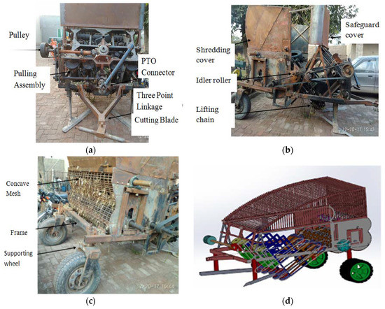
Figure 1.
Cotton Stalk Puller Shredder View; (a) Front View; (b) Side View; (c) Back View; (d) 3D view of the modified machine.
2.3.1. Soil Cutting Blade Assembly
The cotton stalk puller equipped with two blades was attached at an angle to cut the soil as well as cotton stalk from the root system (Figure 2). The depth of cutting the soil was adjusted according to the root depth of the cotton plant. Cutting roots helps in loosening the anchorage of roots in the soil and aids in less uprooting force. This was the first version of the machine. There were no stones found in the cotton field.
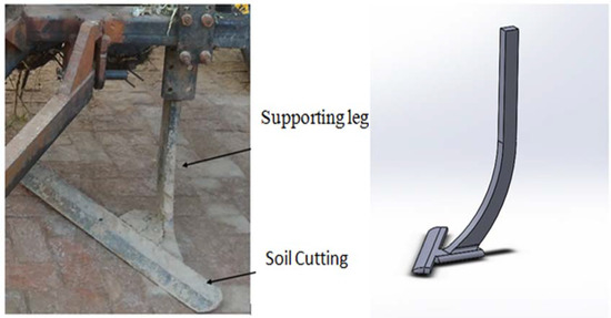
Figure 2.
Soil cutting blade assembly.
2.3.2. Stalk Pulling and Shredding Assembly
This is the assembly used for pulling stalks to feed to shredding assembly. The height of spikes attached with sprockets was adjusted according to the plant. Clearance between the chains was adjusted according to the diameter of the cotton stalk (Figure 3).
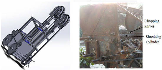
Figure 3.
Stalk pulling and shredding assembly.
The shredding assembly was provided to chop the cotton stalk into small pieces which can be easy to incorporate into the soil. Three cylinders of different diameter were used, which were provided with cutting knives mounted on the surface of the cylinder. These knives are equally spaced and their gap was adjusted according to the required size of the chopped stalk (Figure 3).
2.4. Soil Measurements
Soil physical properties (moisture content, bulk density) were determined by collecting 10 undisturbed soil samples (15 cm long and 5 cm diameter) at random from the experimental field before the commencement of the experiment. The soil was weighed before and after oven-drying, at 105 °C for 24 h to quantify the bulk density and dry basis soil moisture content. (Table 2).
Table 2.
Soil physical and mechanical properties.
2.5. Crop Measurements
The parameters of cotton filed was determined for analyses the forces required for uprooting and cutting the stalk. The most important parameters for crop include depth and thickness of taproot, spreading of lateral roots, the diameter of the stalk, moisture content of stalk, average height of the cotton plant, variety of crop and type of sowing bed. The length of tap root was measured using a measuring tape. The diameter of the cotton stalk was measured using a Vernier caliper. The moisture content of cotton stalk was determined using the oven dry method. Furrow beds were constructed by bed shapers. The seed of cotton crop was planted manually, which resulted in variation in the plant-to-plant and row-to-row spacing (Table 3).
Table 3.
Field parameters of cotton crop.
2.6. Experimental Setup
Cotton stalk puller shredder was tested in two different fields, i.e., the first field (in which cotton stalks have leaves and bolls) and the second field (cotton stalks having few bolls). Three machine forward speeds (1.8, 2, 2.2 km/h) and three levels of engine speed (1500, 1800, 2000 rpm) were used to study their effect on the percentage of pulled cotton stalk, blockage and percentage of bolls crushed.
2.7. Shredding Efficiency
The size distribution of chopped stalk is used as a measure of the shredding efficiency of the machine. Randomly selected the area (3 in each row) of the size 1 × 1 m2 to collect the chopped stalk after operation of puller shredder. The collected chopped was stalk further separated based on size and then determined percentage weightage (Figure 4). The size of these chopped stalks was measured with the help of measuring tape.
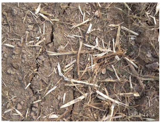
Figure 4.
Size Distribution of Shredded Cotton Stalk.
2.8. Statistical Analysis
To verify the influence of examined factors (explanatory variables) on the observed (dependent) variables, a two-way analysis of variance (ANOVA) was used. An analysis of variance was conducted for each of the following dependent variables: Blockage (%), Bolls crushed (%), Pulled stalk (%). Independent variables were tractor engine speed (rpm) and forward ground speed (km/h). The tractor engine speed had 3 levels (1500, 1800 and 2000 rpm), whereas the forward ground speed also had 3 levels (1.8, 2 and 2.2 km/h).
A least significant difference (LSD) test was used to indicate homogeneous groups. The obtained data were statistically analyzed using the STATISTIX (version 8.1 Analytical Software, Tallahessee, USA). All analyses were conducted at the significance level p = 0.05 [19,20].
2.9. Design Analysis and Optimization Using Computer Software
The mechanical analysis of different machine parts was performed on ANSYS 17.2 academic version to analyze the effect of different stresses acting on cutting blad and main frame. The analysis data provide a basis in design work to utilize suitable material. A static structural analysis was used to study the effect of stresses on total deformation and hence, the forces in structures or components due to loads were determined 3D models of blades attached at different angles and designed using Solidworks software and static structural analyses of these blades were carried out using ANSYS software.
There was a blade attached at four different angles selected for structural analysis using the finite element method. The following four different angles arrangement with the blade were selected:
- Blade attached at 30°.
- Blade attached at 45°.
- Blade attached at 60°.
- Blade attached at 75°.
The dimensions of these blades were measured using a measuring tape. Three-dimensional drawings of these blades were prepared in Solidworks according to dimensions taken.
2.9.1. Building the Model
A solid model of soil cutting blade of cotton stalk puller shredder was created using Solidworks software. The study was focused on the deformation of the blade during cutting operations in soil. Therefore, not all the components of the cotton stalk puller shredder were used in the FEM analysis. The academic version of ANSYS was used for the FEM stress analysis process. The FEM analysis was set up in 3D, linear, static and isotropic material model assumptions. The material used for cutting blade is high carbon steel. The material properties of soil cutting blades are shown in Table 4 below.
Table 4.
Material properties used in the model.
2.9.2. Mesh Generation
To build the finite element model, the blade meshed. The meshing size used was fine to obtain a highly accurate quantitative analysis. Table 5 shows the total number of elements and nodes obtained during meshing operation in three types of blades.
Table 5.
Mesh parameters used in the model.
2.9.3. Boundary Conditions
The boundary conditions are considered the critical factor for the correctness of a calculation. The mechanics of boundary conditions involved in this study was the force and forward speed. For the 85 hp tractor, the maximum force of 3000 N and forward speed 2 km/h were calculated and applied as boundary conditions of the blades.
3. Results and Discussion
3.1. Field Performance
The statistical analysis shows that the operating parameters of machines significantly affected the dependent variables (blockage, bolls crushing and pulled stalk). The interactional effect of forwarding speed and engine speed also significantly (p ≤ 0.05) affected the observed variables.
3.1.1. Machine Performance in Ungrazed Cotton Field Conditions
During the operation of the machine in the field, it was observed that there is some blockage caused by the cotton stalk in pulling assembly. Therefore, the effect of tractor engine speed (rpm) and forward speed (km/h) on the percentage blockage of the cotton stalk in the pulling assembly was determined. The result shows that the maximum percentage of blockage, i.e., 21.33% occurred at a forward speed of 2.2 km/h and engine speed of 2000 rpm, whereas the minimum blockage (9.3%) of cotton stalk occurred when the forward speed was 1.8 km/h, with an engine speed of 1500 rpm, as shown in Figure 5a. After analysis, it was clear that the blockage was caused due to inappropriate forward ground speed of the machine. The feed rate at higher speed was increased; as a result, higher blockage was oberved. At 2 km/h, there was uniform feeding of cotton stalk, which is why there was less blockage.
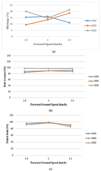
Figure 5.
Machine performance in ungrazed field; (a) Tractor Engine RPM and Forward Speed vs. % Blockage; (b) Tractor Engine RPM and Forward Speed vs. % Bolls Crushed; (c) Tractor Engine RPM and Forward Speed vs. % Pulled Stalk.
One of the objectives of this study was to destroy the cotton bolls which are oviposition sites for pink bollworm. Thus, there was the need to study the effect of various parameters while crushing these bolls. The percentage of cotton bolls crushed was analyzed in relation to forward ground speed (km/h) and engine rpm and the results showed that the maximum percentage of bolls crushed was 97% at a forward speed of 1.8 km/h with an engine speed at 2000 rpm (Figure 5b). From the figure, it can be seen that the forward ground speed does not havemuch effect on cotton bolls crushing (%) but the engine speed has an effect on boll crushing. The rpm of the crushing cylinder is higher at higher engine speeds, which results in more crushing of cotton bolls.
The pulling efficiency of a machine is also an important parameter which has direct effect on the field capacity of the machine. Therefore, the effect of tractor engine rpm and forward speed on the percentage of pulled cotton stalk was determined. It was found that the maximum percentage of pulled cotton stalk, i.e., 97%, was obtained when the engine speed was 2000 rpm and the forward speed of the machine was 2 km/h (Figure 5c). From the graph, it is clear that engine speed has a higher effect on pulling efficiency rather than forward ground speed. Thus, the maximum pulling efficiency was achieved when the engine speed (rpm) was higher with a moderate forward ground speed. Table 6 shows the stalk shredding efficiency of the machine. The cotton stalk puller shredder provides a significant solution for the eradication of pink bollworm. It shreds the cotton stalk into small pieces with a size ranging from 51 to 76 mm, which can be easily incorporated into the soil.
Table 6.
Cotton stalk shedding efficiency.
3.1.2. Machine Performance in Goat Grazed Cotton Field Conditions
The effect on the percentage blockage of cotton stalk was determined in terms of its relationship with tractor engine rpm and forward ground speed. The analysis was done and the results show that maximum blockage of about 17% occurred at an engine speed of 2000 rpm and a forward speed 2.2 km/h, as shown in Figure 6a. Compared to the results of the ungrazed field, there is less blockage in the goat-grazed field. This is due to the low moisture content in this field. The graph shows that there will be a higher blockage at a high forward ground speed and high engine speed (rpm). Thus, it is clear that the engine speed (rpm) has much more effect on the blockage of cotton stalk in pulling assembly than the forward ground speed.
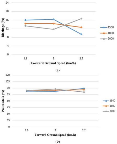
Figure 6.
Machine performance in grazed filed; (a) Tractor Engine RPM and Forward Speed vs. Blockage (%); (b) Tractor Engine RPM and Forward Speed vs. Pulled Stalk (%).
The effect of tractor engine rpm and forward speed on percentage pulled stalk was determined in order to analyze the percentage of remaining cotton stalk in the field and also to determine the pulling efficiency. The results show that the maximum percentage of pulling, i.e., 89% was obtained at 1500 rpm and 2.2 km/h, as shown in Figure 6b. It can be seen that more cotton stalks were pulled at a low engine speed and a high forward ground speed. Therefore, it was concluded that the pulling efficiency of cotton stalk depends mainly on forward ground speed (km/h).
3.2. Design Analysis and Optimization of Cotton Stalk Puller Shredder
3.2.1. Adjustment of Soil Cutting Blade
The adjustment of soil cutting blade was made in terms of its angle with supporting leg. Four different angles (30°, 45°, 60°, 75°) were used to study the deformation under the impact of soil resistance. The suitable angle on which minimum stresses and less total deformation occur can be used in the machine.
Equivalent Stress
Equivalent stress was used in order to predict the yielding of material of soil cutting blade under a static force of 3000 N. The force was applied (along the x-axis) against the movement of the blade in the soil. The maximum equivalent (von-mises) stresses were observed for the blade attached at 30°, the blade attached at 45°, the blade attached at 60° and the blade attached at 75°, as shown in Figure 7.
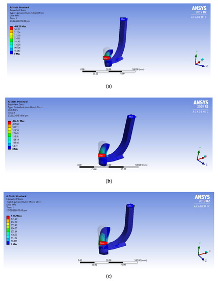
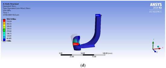
Figure 7.
Equivalent Stress Analysis; (a) Blade attached at 30°; (b) Blade attached at 45°; (c) Blade attached at 60°; (d) Blade attached at 75°.
The equivalent (von mises) stress of the soil cutting blade were analyzed and the results show that the maximum equivalent stress induced in the blade attached at 75° was 584 MPa, whereas minimum equivalent stress was 408 MPa induced in the blade attached at a 30° angle. Thus, after analysis, it could be concluded that the best angle (at which minimum value of max. equivalent stress is obtained) for the attachment of the soil cutting blade is 30°, as shown in Table 7.
Table 7.
Equivalent stress analysis of soil cutting blade.
Principal Stress
Principal stress is normal stress which is calculated at some angle when shear stress is considered as zero. Normal stress can be obtained for maximum and minimum values. The maximum principal stresses were observed for the blade attached at 30°, the blade attached at 45°, the blade attached at 60° and the blade attached at 75°, as shown in Figure 8.
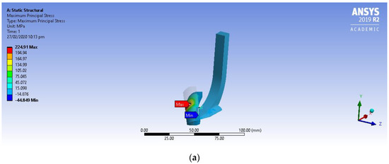
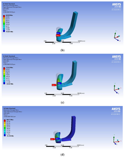
Figure 8.
Maximum Principle Stress Analysis; (a) Blade attached at 30°; (b) Blade attached at 45°; (c) Blade attached at 60°; (d) Blade attached at 75°.
The principal stress analysis of soil cutting blade attached at four different angles was done as shown in Table 8. The results show that the maximum principal stress was induced in the blade attached at angle of 75° whereas minimum principal stress was found to be 225 MPa when the blade was attached at 30°.
Table 8.
Principal stress analysis of soil cutting blade.
Shear Stress
Shear stress is the force that causes layers or parts to slide upon each other in opposite directions. It causes deformation of a material by slippage along a plane or planes parallel to the imposed stress. The maximum shear stresses were observed for the blade attached at 30°, the blade attached at 45°, th eblade attached at 60° and th eblade attached at 75°, as shown in Figure 9.
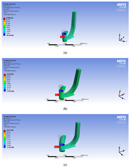
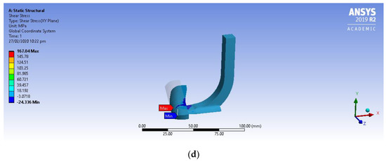
Figure 9.
Shear Stress Analysis; (a) Blade attached at 30°; (b) Blade attached at 45°; (c) Blade attached at 60°; (d) Blade attached at 75°.
The soil cutting blade was analyzed to determine the maximum shear stress induced in it. The results showed that minimum shear stress 52 MPa was observed in blade attached at 30°, while the maximum shear stress found in blade attached at 75° as shown in Table 9.
Table 9.
Shear stress analysis of soil cutting blade.
Directional Deformation
The directional deformation was determined in order to assess the deformation behavior of the cutting blade when it comes into contact with soil. The maximum directional deformation was observed for the blade attached at 30°, the blade attached at 45°, the blade attached at 60° and the blade attached at 75°, as shown in Figure 10. It can be observed that the maximum directional deformation was mm under the load of 3000 N along the x-axis direction.
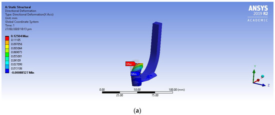
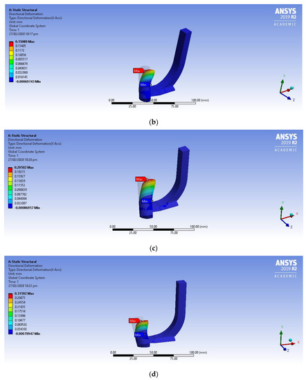
Figure 10.
Directional Deformation; (a) Blade attached at 30°; (b) Blade attached at 45°; (c) Blade attached at 60°; (d) Blade attached at 75°.
The directional deformation of the soil cutting blade was analyzed along the x-axis. The maximum deformation was found to be 0.31 mm when the blade attached at 75°, whereas when the blade was attached at 30° a minimum deformation of 0.12 mm was observed, as shown in Table 10.
Table 10.
Directional deformation in soil cutting blade.
Total Deformation
Deformation is proportional to the stress applied within the elastic limits of the material. It is the overall deformation caused by stress load. The maximum total deformation of the soil cutting blade was observed for the blade attached at 30°, the blade attached at 45°, the blade attached at 60° and the blade attached at 75°, as shown in Figure 11. The total deformation which was observed had maximum value of 0.42 mm against the force of 3000 N.
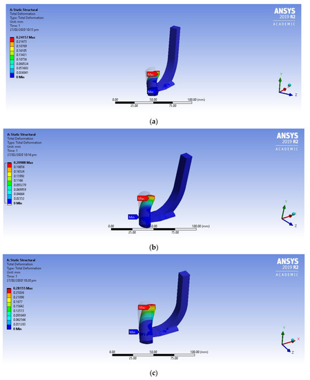
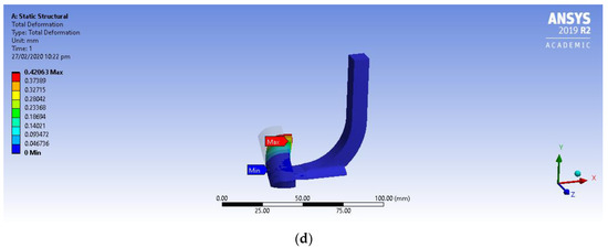
Figure 11.
Total Deformation; (a) Blade attached at 30°; (b) Blade attached at 45°; (c) Blade attached at 60°; (d) Blade attached at 75°.
The total deformation of the soil cutting blade was calculated as shown in Table 11. The maximum total deformation occurred at a 75° angle, whereas the minimum total deformation was 0.20 mm when the blade was attached at 45°.
Table 11.
Total deformation in soil cutting blade.
Safety Factor
It is the load carrying capacity of a machine part beyond the expected or actual load. Essentially, the factor of safety is how much stronger the part is than it needs to be for an intended load. The factor of safety for soil cutting blade was observed for the blade attached at 30°, the blade attached at 45°, the blade attached at 60° and the blade attached at 75°, as shown in Figure 12.
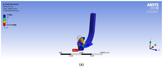
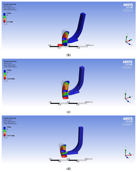
Figure 12.
Factor of Safety; (a) Blade attached at 30°; (b) Blade attached at 45°; (c) Blade attached at 60°; (d) Blade attached at 75°.
The factor of safety of the soil cutting blade was determined at four different angles. The minimum factor of safety was 0.11 for a blade angle of 45°, as shown in Table 12.
Table 12.
Factor of safety of soil cutting blade.
3.2.2. Analysis of Frame
The cotton stalk puller shredder was attached with a tractor with the help of three-point linkage which is further attached with a frame to pull it. The load acts at the attachment point and on the channel frame of the machine. Therefore, the analysis was done in order to calculate stress and total deformation that could act as failure constraints. Table 13 shows the analyses of frame.
Table 13.
Analysis results of frame.
Equivalent Stress
Equivalent stress (Von Mises stress) is a value used to determine if a given material will yield or fracture. It is mostly used for ductile materials, such as metals. The von Mises yield criterion states that if the von Mises stress of a material under load is equal or greater than the yield limit of the same material under simple tension, then the material will yield. The maximum value of equivalent stress is 520 MPa, which was determined using FEA (Figure 13).
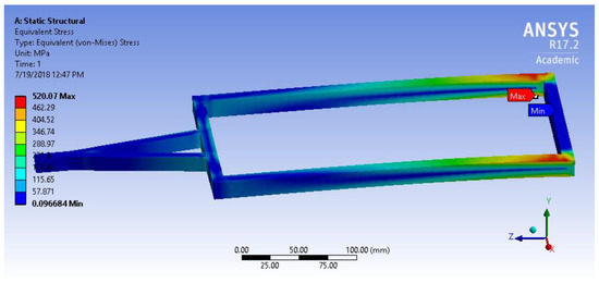
Figure 13.
Equivalent Stress acting on Frame.
Maximum Shear Stress
The maximum shear stress is the maximum concentrated shear force act on a small area. Its value was determined using ANSYS and was found to be 263 MPa. From our analyses, it can be noted that all of the highest shear stress es acted at the upper and lower surfaces of the frame (Figure 14).
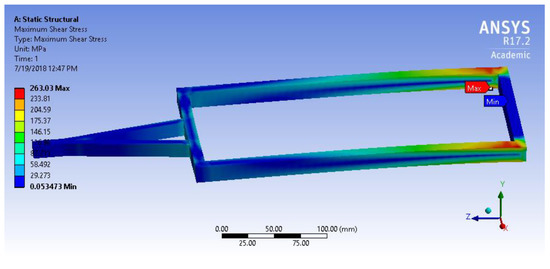
Figure 14.
Maximum Shear Stress acting on Frame.
Equivalent Elastic Strain
The equivalent elastic strain is the limit for the values of strain up to which the object will rebound and come back to the original shape upon the removal of the load.No part of the object under stress had undergone permanent deformation. The maximum calculated value of the equivalent elastic strain is 2.6 × 10⁻³ mm/mm. From our analyses, it is noted that all of the highest elastic strain occurrf near the fixed end of the frame (Figure 15).
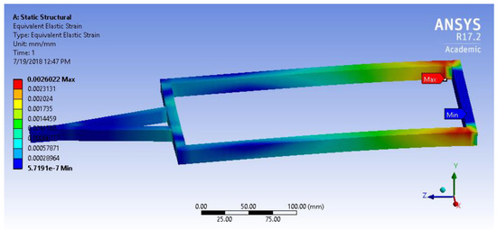
Figure 15.
Equivalent Strain on Frame.
Total Deformation
Deformation refers to any change in the shape or size of an object which is caused in a body due to an applied load (the deformation energy in this case is transferred through work) or a change in temperature. The total deformation that occured in the frame was 14 mm under a static load (Figure 16).
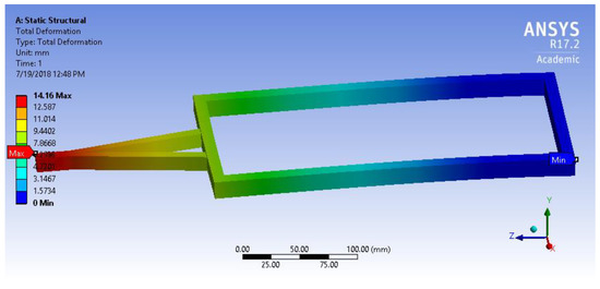
Figure 16.
Total Deformation in Frame.
Directional Deformation
Directional deformation can be put as the displacement of the system in a particular axis or user-defined direction. The deformation in a frame occurs on the z-axis towards the direction of the pull as it is mounted with the help of three point linkage. The maximum value of the directional deformation obtained after analysis was 0.68 mm (Figure 17).
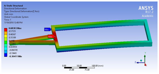
Figure 17.
Directional Deformation in Frame.
4. Conclusions
The foremost objective of the puller sherdder was to abolish and chop the cotton bolls, which are oviposition sites for pink bollworm. The pink bollworm is considered a dangerous pest for cotton crop as it has ability to hide in the soil and then attack the cotton crop during the next season. The cotton stalk puller shredder provides a significant solution for the eradication of pink bollworm host. It shreds the cotton stalk into small pieces ranging in size from 51 to 76 mm which can be easily incorporated into the soil. The maximum pulling (%) of cotton stalk, i.e., 99%, was achieved when machine was operated at 2000 rpm and 2 km/h. Minimum blockage of cotton stalk occurred at 2 km/h and 2000 rpm. The maximum bolls crushed was 98% at a forward ground speed of 1.8 km/h with an engine speed of 2000 rpm. The suitable angle for the soil cutting blade must be 30° because the minimum stress 408 MPa was induced at this angle. The appropriate mesh size 38 × 13 mm must be used for efficient crushing of cotton bolls. Further study can be conducted in order to analyze the impact of the incorporation of a cotton stalk on the yield of the next crop.
Author Contributions
Conceptualization, F.A., M.T.J., A.A.K. and Z.M.-K.; methodology, F.A., M.T.J. and A.A.K.; software, F.A. and M.T.J.; formal analysis, F.A., M.T.J., J.M. and F.A.C.; data curation, F.A. and M.T.J.; writing—original draft preparation, F.A., M.T.J. and A.A.; writing—review and editing, F.A., M.T.J., A.A.; Z.M.-K. and B.Q.; supervision, F.A., A.A.K.; and B.Q.; funding acquisition, A.A. and B.Q. All authors have read and agreed to the published version of the manuscript.
Funding
This research was supported by the National Key Research and Development Plan (No2017YFD0701005) and Funded Project by Higher Education Commission, Pakistan (TDF053).
Acknowledgments
The authors are thankful to Bahauddin Zakariya University, Multan Pakistan and Agritech. Pvt. Ltd. Multan, Pakistan for providing the lab facilities.
Conflicts of Interest
The authors declare no conflict of interest.
References
- Government of Pakistan, Ministry of Finance. Pakistan Economic Survey 2017–18; Government of Pakistan: Islamabad, Pakistan, 2017.
- Guoliang, C.; Zhang, X.; Sunling, G.; Zheng, F. Investigation on emission factors of particulate matter and gaseous pollutants from crop residue burning. J. Environ. Sci. 2008, 20, 50–55. [Google Scholar]
- Bansal, N.K.; Sharma, D.N.; Jain, M.L. Development and field evaluation of a stubble collector-cum-planker. Agric. Mech. Asia Afr. Lat. Am. 1987, 8, 57–59. [Google Scholar]
- Yumak, H.; Evcim, Ü. A two-row cotton stalk pulling machine. In Proceedings of the International Congress on Mechanization and Energy in Agriculture, Adana, Turkey, 1–4 October 1990; pp. 416–425. [Google Scholar]
- Gangade, C.; Patil, P.; Dhanphule, S. Comparative study of different methods of cotton stalk removing. PKV Res. J. 2000, 24, 87–89. [Google Scholar]
- Sheikh, E.D.A.G.E. Development and performance of 2-unit diggers for cotton stalks uprooting and groundnut lifting. AMA Agric. Mech. Asia Afr. Lat. Am. 2000, 31, 52–56. [Google Scholar]
- Ramadan, R.Y.Y. Development and evaluation of a cotton stalks puller. J. Soil Sci. Agric. Eng. 2010, 1, 1061–1073. [Google Scholar] [CrossRef]
- Murugesan, R.; Shukla, S.; Patil, P.; Arude, V. Design and Development of Tractor-drawn Cotton Stalk Puller-cum-Chipper. Agric. Eng. Today 2004, 28, 1–6. [Google Scholar]
- Sridhar, N.; Surendrakumar, A. Shredding efficiency of agricultural crop shredder as influenced by forward speed of operation, number of blades and peripheral velocity. Int. J. Appl. Innov. Eng. Manag. 2016, 5, 129–137. [Google Scholar]
- Karale, D.; Khambalkar, V.; Kankal, U. Development and testing of tractor operated slasher. Int. J. Agric. Eng. 2014, 7, 160–164. [Google Scholar]
- Bosrotsi, C.; Addo, A.; Dzisi, K.; Agodzo, S. Development of a Yam Harvester using Finite Element Method. Int. J. Mod. Stud. Mech. Eng. 2017, 3. [Google Scholar] [CrossRef]
- Gavali, M.; Kulkarni, S. Development of Rotary weeder blades by Finite Element Method. Int. J. Sci. Res. Eng. Technol. 2014, 3, 941–945. [Google Scholar]
- Jahanbakhshi, A.; Darreh, S.H.R.; Kheiralipour, K. Stress Analysis of Crossbar of Moldboard Plough Pulled by Massey Ferguson 285 and 299 Tractors. Adv. Appl. Sci. 2017, 2, 11. [Google Scholar] [CrossRef][Green Version]
- Upadhyay, G.; Raheman, H.; Rasool, S. Three dimensional modelling and stress analysis of a powered single acting disc harrow using FEA. Curr. Agric. Res. J. 2017, 5, 203–219. [Google Scholar]
- Makange, N.; Parmar, R.; Tivari, V. Stress analysis on tine of cultivator using finite element method. Trends Biosci. 2015, 8, 3919–3923. [Google Scholar]
- Jafari, R.; TavakoliHashjin, T. Performance evaluation of modified bentlegPlow using finite element approach. Iran Agric. Res. 2016, 35, 63–72. [Google Scholar]
- Tarighi, J.; Ghasemzadeh, H.R.; Bahrami, M.; Abdollahpour, S.; Mahmoudi, A. Optimization of a lower hitch link for a heavy duty tractor using finite element method. J. Fail. Anal. Prev. 2016, 16, 123–128. [Google Scholar] [CrossRef]
- Kumar, D.; Mohanraj, P. Design and analysis of rotavator blades for its enhanced performance in tractors. Asian J. Appl. Sci. Technol. 2017, 1, 160–185. [Google Scholar]
- Francik, R.; Krośniak, M.; Sanocka, I.; Bartoń, H.; Hebda, T.; Francik, S. Aronia melanocarpa treatment and antioxidant status in selected tissues in Wistar rats. BioMed Res. Int. 2014, 2014. [Google Scholar] [CrossRef] [PubMed]
- Francik, R.; Kryczyk-Kozioł, J.; Francik, S.; Gryboś, R.; Krośniak, M. Bis (4, 4′-dimethyl-2, 2′-bipyridine) oxidovanadium (IV) sulfate dehydrate: Potential candidate for controlling lipid metabolism? BioMed Res. Int. 2017, 2017. [Google Scholar] [CrossRef] [PubMed]
© 2020 by the authors. Licensee MDPI, Basel, Switzerland. This article is an open access article distributed under the terms and conditions of the Creative Commons Attribution (CC BY) license (http://creativecommons.org/licenses/by/4.0/).