1. Introduction
Cutting assemblies are some of the most important working assemblies of the machines for harvesting and processing plant material. One of the important ways to lower the costs of production, for example of biomass, is a decisive reduction of the energy costs for obtaining materials for its production. This may be achieved by designing and using working machines equipped with mechanisms of low energy demand.
In Poland, production of basic cereals’ straw and of rape amounts to approximately 34 million tons (Central Statistical Office in Poland; GUS). In practice, the cereals’ straw and rape may be utilized for energy, fodder purposes, or bedding for animals, or may be left in the field and ploughed. However, appropriate straw utilization requires it to be cut into chaff earlier; that is, into pieces of appropriate length. Pieces of agricultural machinery called chaff cutters (the basic working assembly for cutting the plant material into pieces of specific length, in which the drum cutting assembly may be found) are used for this purpose. The specific design and function of the drum cutting assembly results from several areas, including the fact that the cutting process realized by it concerns plant materials, the structure of which is heterogeneous and the physiochemical properties of which have not been fully defined [
1,
2,
3,
4,
5,
6,
7]. Because of the point character of the studies conducted so far, they cannot explicitly determine which features and design parameters of the drum cutting assembly have a decisive impact on cutting efficiency. The Sankey power balance for chaff cutters unambiguously results in power absorption by the cutting assembly clearly dominating above the powers consumed by the machine’s remaining cutting assemblies, and it amounts to 75–80% [
8,
9,
10,
11,
12]. The existing design solutions for the cutting assemblies are characterized by high cutting process energy consumption and the fact (which is, in the end, connected with this) that their power transmission systems are equipped with high power engines. This indicates that the known design solutions have been developed, to a large extent, on the basis of a design intuition.
2. Materials and Methods
2.1. Purpose of the Studies
The issues related to cutting plant material are a topic currently being taken up by many authors. Publications dealing with that issue mainly address the mechanics of the quasi-statistical cutting of selected plants, not taking into consideration the specificity of the cutting assemblies’ construction and the cutting process’s dynamics, which we deal with in practice [
13,
14]. There is also no precise information on the material examined in laboratory tests. The results of these studies are very often incomparable because of differences in the programs and methodology of the studies. That is why there is such an urgent need to supplement knowledge within that scope. The authors of the study have taken up an attempt to supplement knowledge within that scope by conducting experimental studies of cross-cutting and diagonal cutting with the use of a classical and a new cutting drum design made according to our own design solution (Polish Patent Office, RP W.115202) [
15]. The classical design of a cutting assembly is of the shape of a roller and is fit for material layer cross-cutting. However, the new construction is of the shape of a double truncated cone and, by using it, cross-cutting in two directions may be conducted. This new construction of the cutting drum has been developed and patented [
15,
16].
On account of this, experimental determination of the impact of selected features, and operation parameters of the mentioned cutting assemblies’ drum construction, on the cutting efficiency for plant material’s layers, in the form of rye straw, have been assumed as the study’s purposes.
2.2. Plan and Programme of the Studies
For the purposes of the experimental studies’ realization, the plan of the studies has been scheduled, with the independent variables being:
- (1)
Cutting speed (m·s−1).
- (2)
Plant material’s compaction degree h/h0 (…).
- (3)
Plant material’s cutting angle α (…°).
Cutting speed
is the resultant speed of the cutting knife’s peripheral speed
and the speed at which the plant material is fed
by press-feeding rollers. The dependence between these speeds is described by the formula
where
ψ is the angle between the speed vectors
and
.
It has been assumed that the speed of cutting by the drum’s knife shall take the values 2.00, 2.50, and 3.00 m·s−1. The listed cutting speeds ensure the appropriate cutting of the plant material’s layer and correspond to the values of the cutting speed reached in known designs of working machines of the chaff cutter type.
The degree of the material’s compaction has been assumed as the ratio of the plant material layer height, following compaction h, to the material’s height prior to compaction h0. During the studies, the degree of the material’s compaction shall assume the values 0.3, 0.5, and 0.7. The values of h/h0 assumed in the studies’ program are similar to the recommended ones assumed in the phase of pulling-crushing assemblies.
The angle of the material layer cutting has been defined as the angle included between the direction of material’s feeding and the cutting edge of the cutting drum’s knife. The values of the material’s cutting angle α have been assumed based on the studies of the authors and studies described in literature concerning the cross-cutting (α = 0°) of single plants. However, for the purposes of the experimental studies, the authors have assumed that the plant material’s layer, apart from cross-cutting (α = 0°), shall be also cut diagonally (α = 15°, 30°, and 45°). So, cross-cutting concerns only a cutting drum of a classical design and diagonal cutting is related to a cutting drum of the conical type.
However, the following have been assumed as the dependent variables:
- (1)
Efficiency of the cutting process W (kg·s−1).
- (2)
Unit energy consumption for cutting material E (J·kg−1).
- (3)
Unit cutting resistance pc (N·m−1).
The efficiency of the cutting process has been defined as the ratio of mass m of the chaff obtained in defined time
t of the cutting process; that is,
The unit cutting operation was calculated from the relation
where
P is the power on the cutting drum’s shaft and
W is the efficiency of the cutting process.
The power on the cutting drum’s shaft during cutting was calculated from the relation
where
Mcsr is the mean turning moment of cutting on a drum’s roller and
ω is the angular speed of the cutting drum’s roller.
The mean turning moment of cutting,
Mcsr, has also been determined from the equation
where
Mbsr is the mean moment needed to overcome all the cutting assembly’s resistances and
Mjsr is the mean moment of no-load running.
The unit cutting resistance has been defined as the limiting unit pressure on a blade, referred to its length, where the cutting of material starts. In practice, it is assumed that the point of applying the force N, being the resultant of the unit cutting resistances, is in the middle of the active length of the cutting edge ∆l.
The experiment has been planned as per the cross three-factor classification type 3 × 3 × 4. Five replications per sample were applied during the studies. The number of replications was determined based on preliminary studies and their statistical evaluation.
2.3. Test Bed
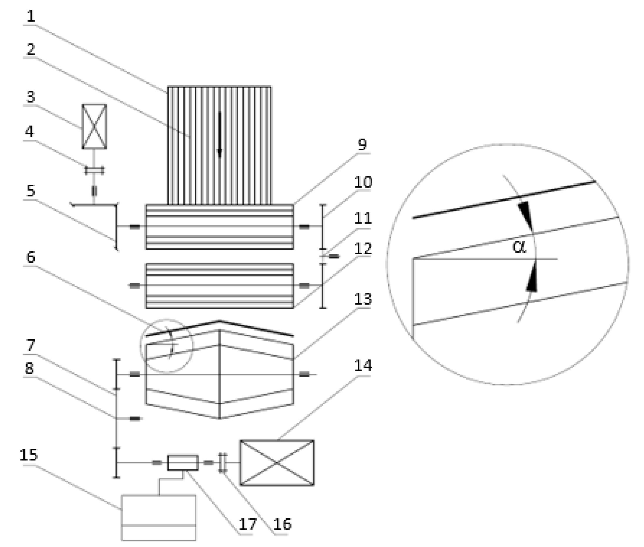
For the purposes of the experimental tests’ realization, a test bed was designed and constructed for testing the cutting process of the plant material’s layer, including rye straw (winter rye Dańkowskie Złote). The test bed makes it possible to realize the process with the use of replaceable cutting drums of the cylindrical or double truncated cone types. The construction diagram of the test bed is presented in
Figure 1. All the essential assemblies of the test bed are fastened to the frame bearer made of steel sections. Power transmission from the electric motor (14) through coupling (16) is transferred to the measurement system of the turning moment and rotational speed (17) and then to the gear belt transmission (7) and directly to the cutting drum (13) of a cylindrical or truncated cone type. The belt transmission (7) has the tension roll (8). The crosscut edge (6), made of steel flat bar, is also replaceable and it is used geometrically (straight or broken section) for a given shape of a cutting drum. Material to be cut (2) is fed in the form of sheaves to a trench (1). It is pressed and pulled in by the pulling-crushing rollers: the upper (9) and bottom one (12). The cutting speed of the plant material is regulated by the rotational speed of the electric motor’s shaft (14), rotations of which may be changed with an inverter (a frequency converter). The degree of the material’s layer compaction is regulated by a change of a gap between the upper (9) and bottom roller (12). Power transmission to the rollers is transmitted from the electric engine (3) through a coupling (4) and bevel gearbox (5). Revolutions of the electric motor (3) may also be changed by an inverter (a frequency converter). However, the drive between the rollers (9) and (12) is realized with the use of the stretcher, which makes it possible to change the gap between the pulling-crushing rollers. It is enough to lower the upper roller (9) by unscrewing the clamping screws and then screwing them in a determined position by the chaff cutter’s service staff and shifting the roller (11), tightening the cogbelt. The cutting angle, in the case of a conic cutting drum, is regulated with the use of replaceable shields on the drum’s roller and an appropriate adjustment of spherical joints that the cutting knives are fastened to.
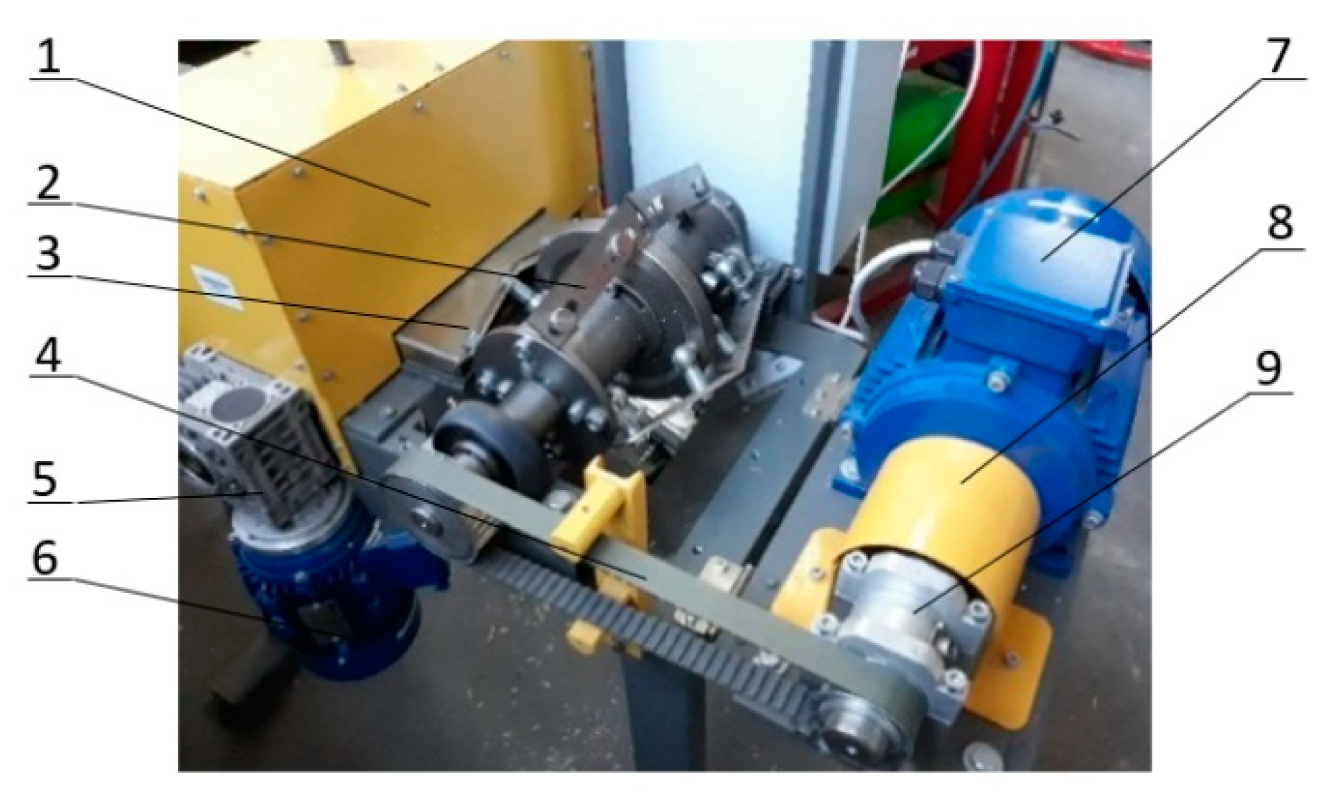
Figure 2 presents an exemplary construction of a cutting drum of the conic type assembled in a chaff cutter, together with the engine driving it via belt transmission of toothed type. Thus, the design of the test bed guarantees the conducting of experimental tests concerning the plant material’s layer cutting process while exercising the assumed values of independent variables.
2.4. Methodology of the Studies
Samples for the studies have been prepared for the purposes of conducting the tests concerning the cutting efficiency for the rye straw’s layers. Ears have been cut and single stalks have been linked together, forming the so-called sheaves of average length
l = 850 mm. The length was measured with a universal caliper with accuracy up to 1 mm. Then, each sample was weighed on an electronic scale (make ELDOM, model EK3130) with accuracy up to 2 g. The approximate number of stalks in a sample was 280 pieces. Additionally, the diameter of the stalks was measured with the use of electronic slide caliper L150IP54 with accuracy up to 0.01 mm. The diameter of the stalks was within the range of values 2.5–6.3 mm. Before the studies, the plant material was kept in a dry room, and moisture content on the day the tests were conducted was w = 12%. The material’s moisture content was determined based on randomly selected samples with the oven-drying method. The prepared samples, in the form of sheaves, were placed in the test bed’s feeding trough; the bindings were cut and cutting was performed. The degree of the material’s compaction
h/h0 was determined on the basis of measurement of the layer’s height before and after compaction. Measurement of the height
h/h0 was conducted with the use of a universal caliper with accuracy up to 1 mm. Realization of the plant material’s compaction took place with the use of the press-feeding rollers’ assemblies and pressing elements, maintaining a constant value of the material’s compaction degree
h/h0 at the time of the material’s tracking in the direction of the cutting drum (
Figure 1). An appropriate angle of the plant material’s layer cutting was determined with the use of a workshop protractor of the measuring range 0–360° and measurement accuracy 5′. The requested values of the plant material’s feeding
vm were obtained by an appropriate selection of the lower roller’s rotational speed (12). The roller’s rotational speed (12) was measured on its roller with the use of a contact tachometer LCD with measurement precision 0.05% + 1. At the stage of determining the value
vm, the slide of the plant material in relation to the press-crushing rollers’ surface was considered. The value of the slide was assumed as 10%, which was confirmed by experimental tests [
15,
16,
17]. Based on the calculated values of speed
vm, the required values of rotational speeds of the cutting drums of the roller or truncated cone types were determined in order to obtain the appropriate peripheral speed of the drum
vb to ensure the cutting speed
vc assumed in the cutting speed tests’ program. However, for the cutting drums of the roller type, the peripheral speed of a drum
vb takes the constant speed along the whole length of the cutting knives. In the case of the cutting drum of the conical type, the peripheral speed
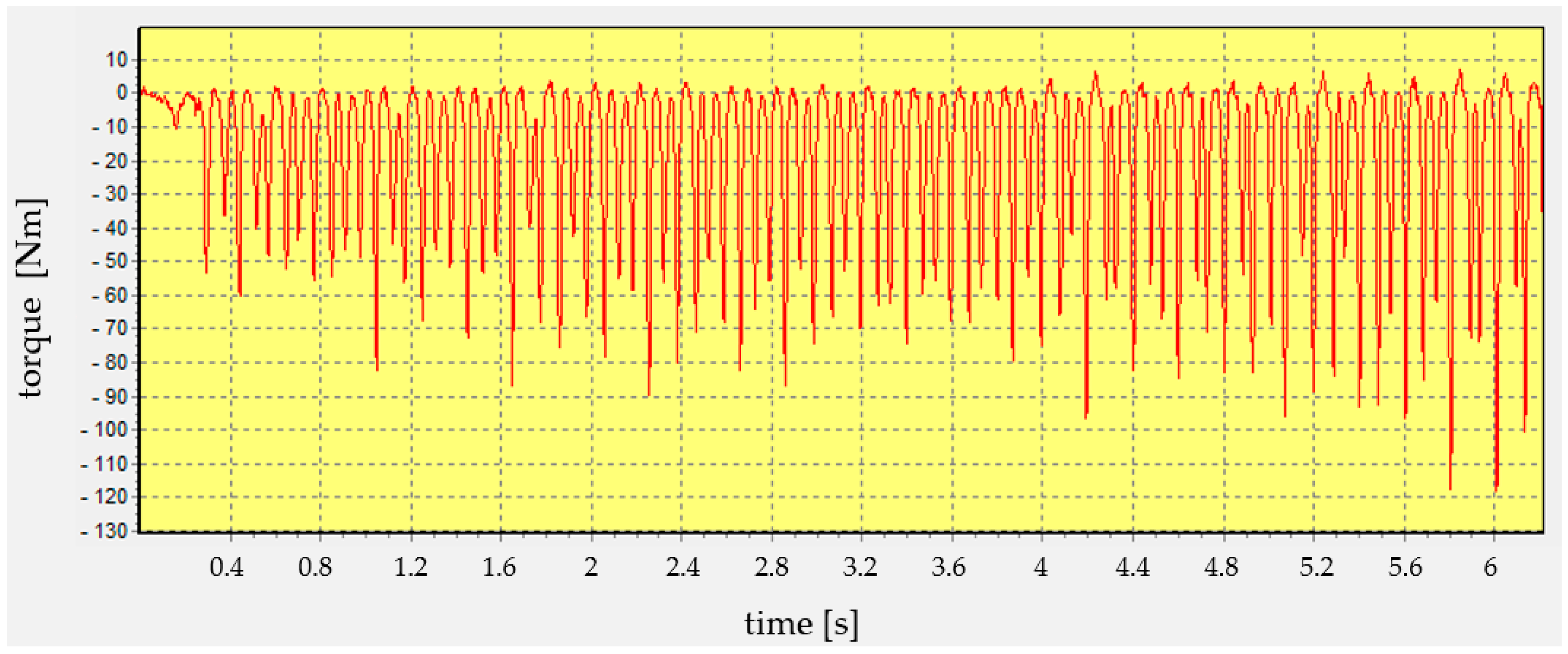
vb was determined in the mid-length of the cutting knives’ blades. A torque meter with speed indicator MIR20, which was directly interconnected with two-channel measuring instrument MW2006-4, was used for the purposes of measuring the turning moment and revolutions on the cutting drum’s roller while idle and operating. During the studies, a computer system with a program for data registering and the author’s computing program RB01 was used. An exemplary course of the values registered at the time of measurement is presented in
Figure 3. The efficiency of the cutting assembly
W was determined experimentally by the measurement of the cutting time
t of a given sample of plant material and weighing of mass
m of the chaff collected from each sample. For the purposes of measuring the chaff mass, the electronic scale (make ELDOM, model EK3130) of accuracy up to 2 g was used. During the experimental tests, the time of a single measurement fell within the range from 30 to 60 s and depended on the speed of the plant material’s feeding. The time of measurement was measured with a chronograph with accuracy up to 0.01 s.
3. Results
The obtained results from experimental tests of the process of cutting plant material into pieces of defined length, were subject to statistical analysis, within the frames of which the arithmetic averages
,
, and
were calculated from a given sample for five replicates, with standard deviations
,
, and
, and variation coefficients
,
, and
, expressed in percent. Moreover, analysis of regression was conducted and showed that, at the level of significance
αgr = 0.05 at the multiple correlation coefficient
R, from 0.80 to 0.90, the independent variables
vc,
h/h0, and α have an essential impact on the values of dependent variables
W, E, and
pc. Values of the mean values
,
, and
are presented in
Figure 4,
Figure 5,
Figure 6,
Figure 7,
Figure 8 and
Figure 9.
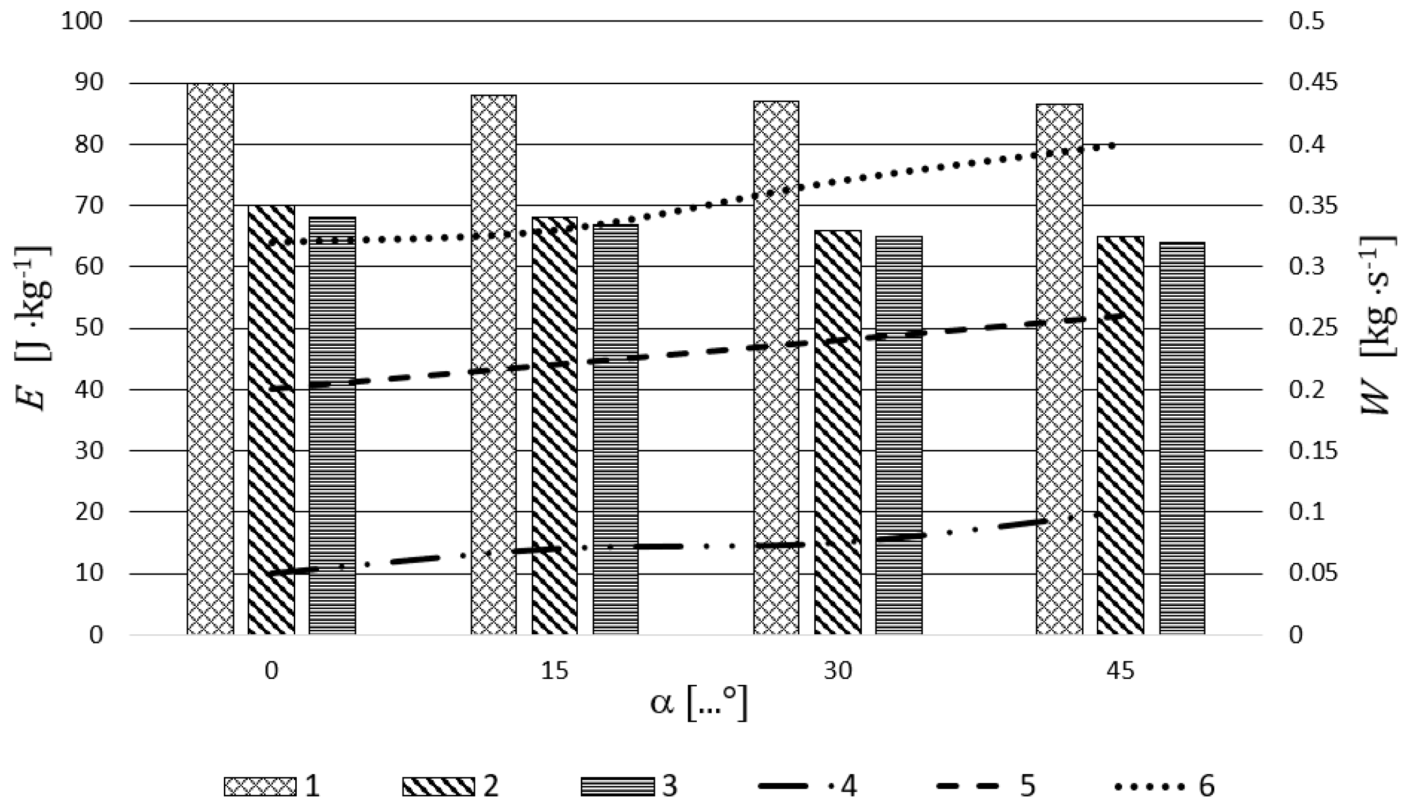
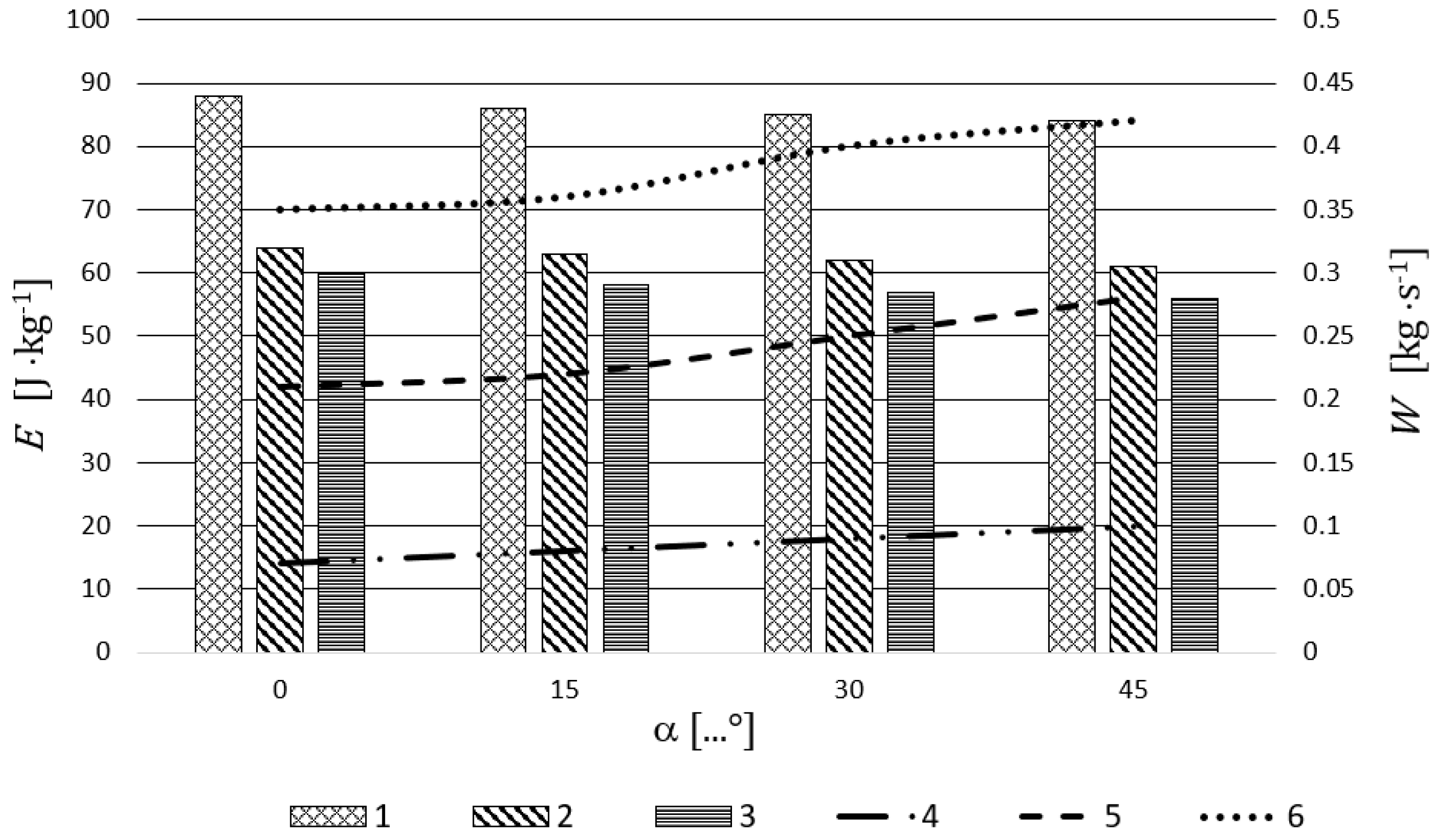
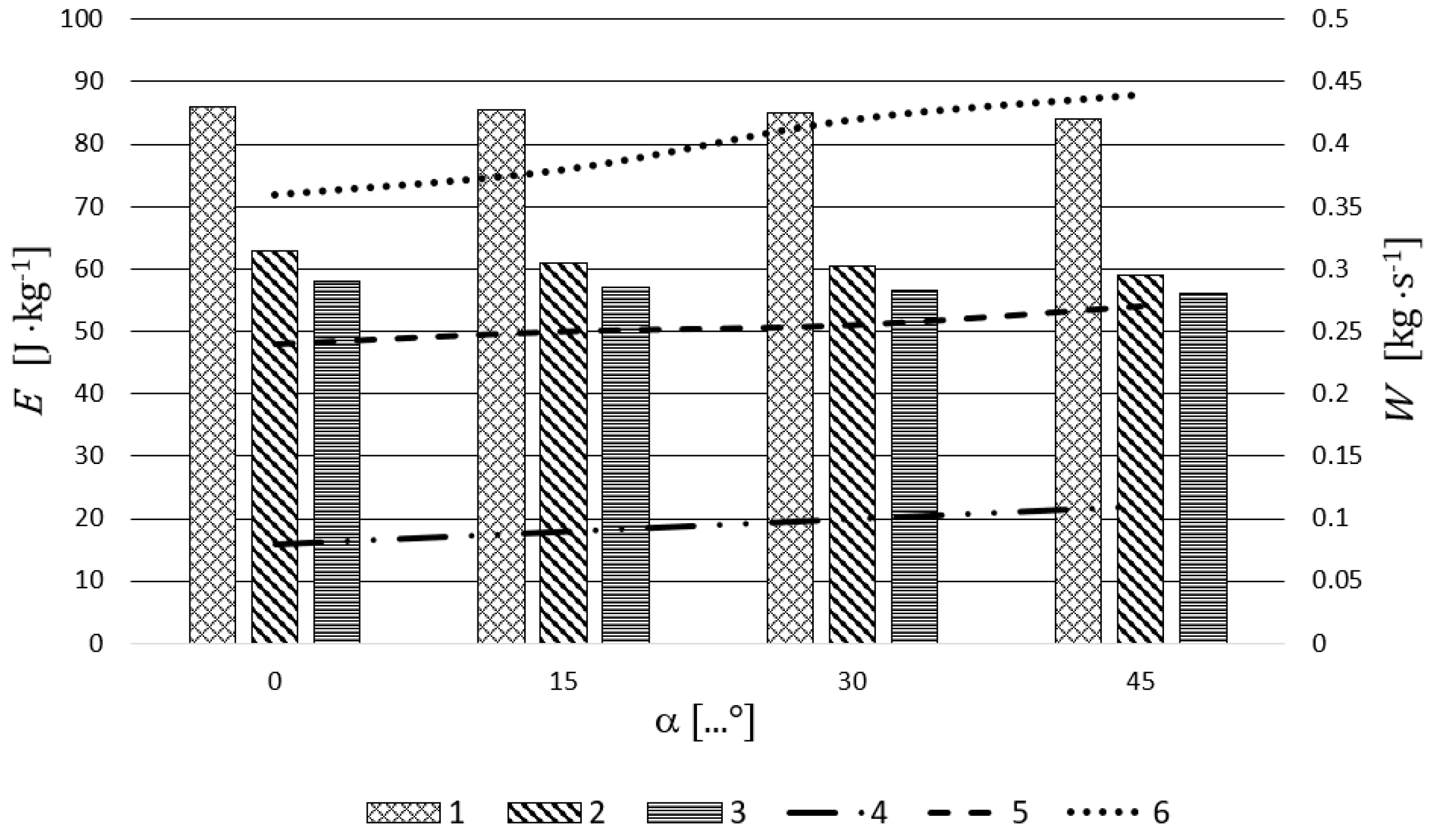
Figure 4,
Figure 5 and
Figure 6 present the exemplary characteristics of the unit energy consumption
E and efficiency
W of cutting drums of the classical and new designs at the time of cutting rye straw for three cutting speeds
vc, three degrees of the straw layer’s compaction
h/h0, and four plant material cutting angles α.
From the analysis of
Figure 4,
Figure 5 and
Figure 6 it results that the cutting process’s efficiency
W increases definitely together with the cutting speed’s increase, regardless of whether we are dealing with a cutting drum of a roller or truncated cone type. This assumes the highest values, roughly equal to
W = 0.44 kg·s
−1 for a truncated cone drum design of cutting angle α = 45° and cutting speed
vc = 3.0 m·s
−1. The lowest efficiency values, roughly equal to
W = 0.05 kg·s
−1, have been obtained for the classical design of a cutting drum at the cutting speed
vc = 2.0 m·s
−1.
The experimental studies conducted at the time of cutting the rye straw have clearly showed that the use of a construction of a double truncated cone of a cutting drum results in a significant increase in the cutting process’s efficiency as compared to the classical (that is, the roller) design. It clearly results from the diagrams shown in
Figure 4,
Figure 5 and
Figure 6 that, together with the increase of the degree of the material’s compaction
h/h0 = 0.7–0.3, there occurred a slight drop in the efficiency
W of the cutting process, which accompanied a bigger material compaction. This is caused by the increase of resistance of the plant material’s displacement in the cutting drum’s direction.
It also unambiguously results from the analysis of the studies’ results presented in
Figure 4,
Figure 5 and
Figure 6 that the unit consumption of energy
E decreases together with the increase of the cutting speed
νc. The lowest values,
E = 56 J·kg
−1, have been obtained for the cutting drum of truncated design at the cutting speed
νc =3.0 m·s
−1, material cutting angle α = 45°, and degree of the material’s compaction
h/h0 = 0.7. However, the highest values of the unit energy consumption,
E = 90 J·kg
−1, have been received for the cutting drum of classical design at the cutting speed
νc = 2.0 m·s
−1 and degree of the material’s compaction
h/h0 = 0.3. The conducted experimental studies have shown that an essential impact on the unit energy consumption
E (apart from the cutting speed
νc and the degree of material’s compaction
h/h0) is made by the cutting angle α. The lowest values of the unit energy consumption
E have, in each case, been received for the cutting angle α = 45°. This results, most of all, from the fact that the material is cut along its longer length at the same feeding width and thickness, which, as an effect, results in obtaining higher effectiveness for the
W process. It should be stressed here that cutting plant material at the angle of its symmetry axis results in a lower unit cutting resistance as compared to cross-cutting. In the case of cutting through plant material, the size of the section area does not have such a significant impact on cutting resistances as in the case of cutting, for example, steel pipes. This results, most of all, from the structural plant material’s structure, which is different to steel and reveals strong features of anisotropicity.
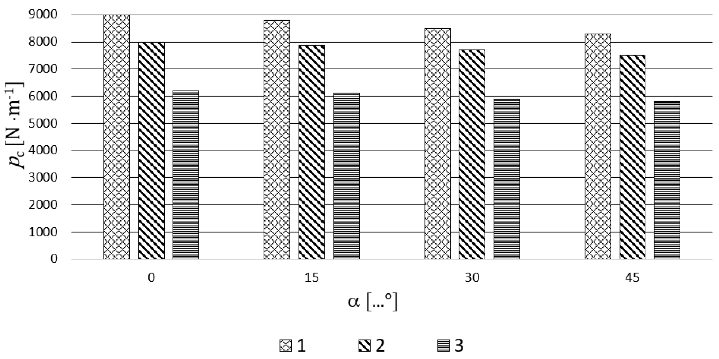
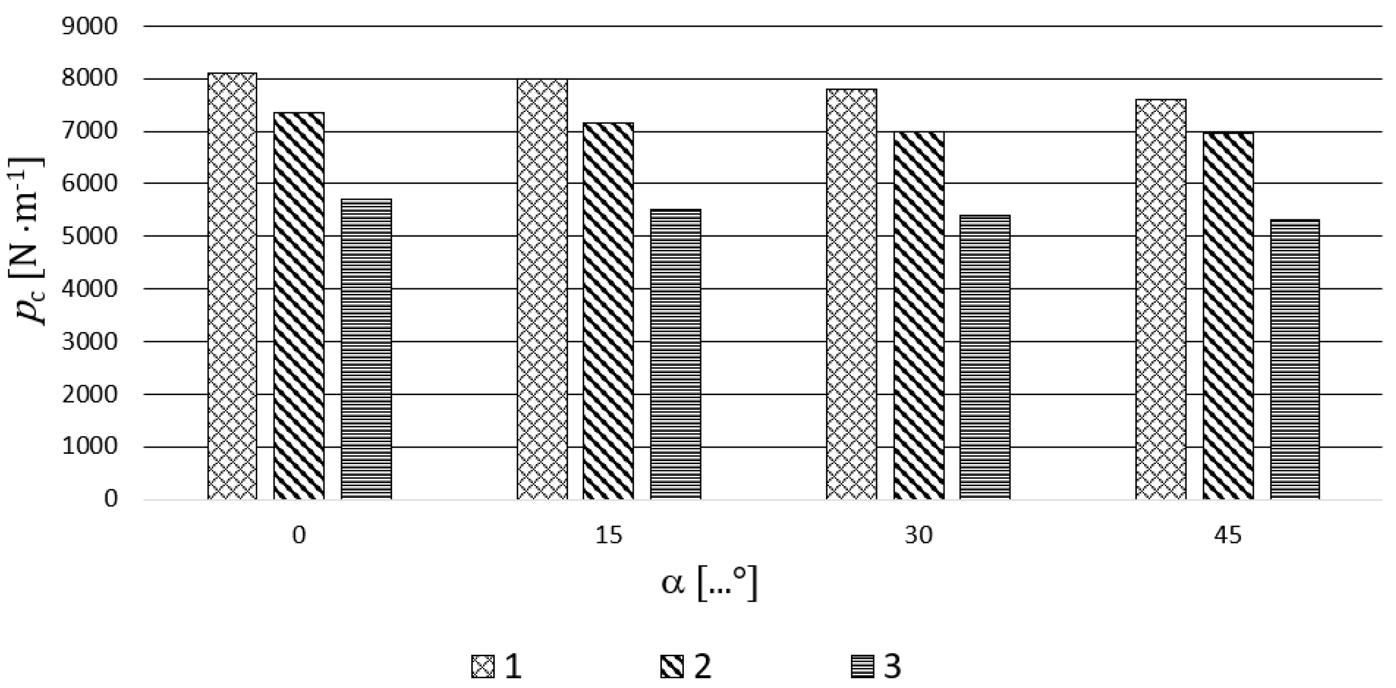
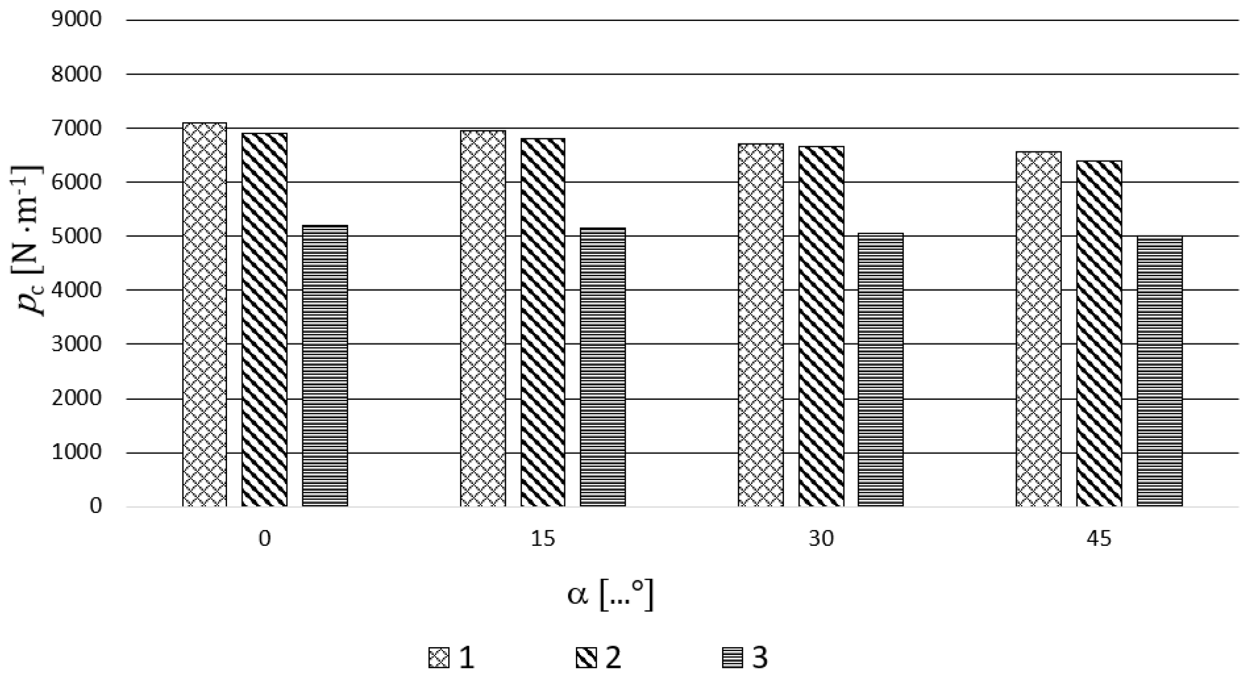
Figure 7,
Figure 8 and
Figure 9 present, in a graphic form, the impact of selected independent variables on the unit cutting resistance
pc. It results from the analysis of
Figure 7,
Figure 8 and
Figure 9 that the unit cutting resistance
pc of the plant material’s layer decreases decidedly together with the increase of the cutting speed
νc, irrespective of whether we deal with a classical or a new design of cutting drum. The highest values it assumes approximately equal
pc = 9000 N·m
−1 for the classical construction of the cutting drum (α = 0°), cutting speed
νc = 2.0 m·s
−1, and the degree of material’s compaction
h/h0 = 0.3. However, the lowest values of the unit cutting resistance, approximately equal to
pc = 5000 N·m
−1, have been obtained for the truncated design of the cutting drum (α = 45°), cutting speed
νc = 3.0 m·s
−1, and the material compaction degree of
h/h0 = 0.7.
The conducted experimental studies have unequivocally shown that, for all the studied values of the cutting angle α, the impact of the cutting speed νc on the unit cutting speed pc is approximately the linear function and that, together with the cutting speed increase, the unit cutting resistance decreases. Together with the material’s degree of compaction h/h0, the unit cutting resistance pc increases and the dependence is approximately linear and has the same course for all the studies’ values of the angle α. The experimental studies have clearly shown that the use of a new cutting drum design of a truncated type contributes to the decrease of the unit plant material’s layer cutting resistance. This fact is desired in every respect as it results in lower demand for power consumption on the cutting drum’s roller.
The authors of the study did not have the possibility to directly compare the results of their studies with the ones presented in the literature by other researchers. This is caused by the fact that the results of the studies presented in this article mainly concern the new design on the drum cutting assembly, which is covered by legal protection. In the specialist literature there are no data that would describe the process of cutting rye straw into chopped straw with the use of a chaff cutter drum of the double truncated cone shape. The first proposal of the cutting drum’s design of that shape, which can realize diagonal cutting in both directions, has been presented by Bochat [
15]. Other authors in their studies present only the data connected with the commonly functioning design constructions of cutting drums realizing lateral cutting. The results presented above by the authors concerning the classic design of the drum cutting assembly are comparable with the data presented in the literature from within that scope [
3,
12,
13,
17,
18].
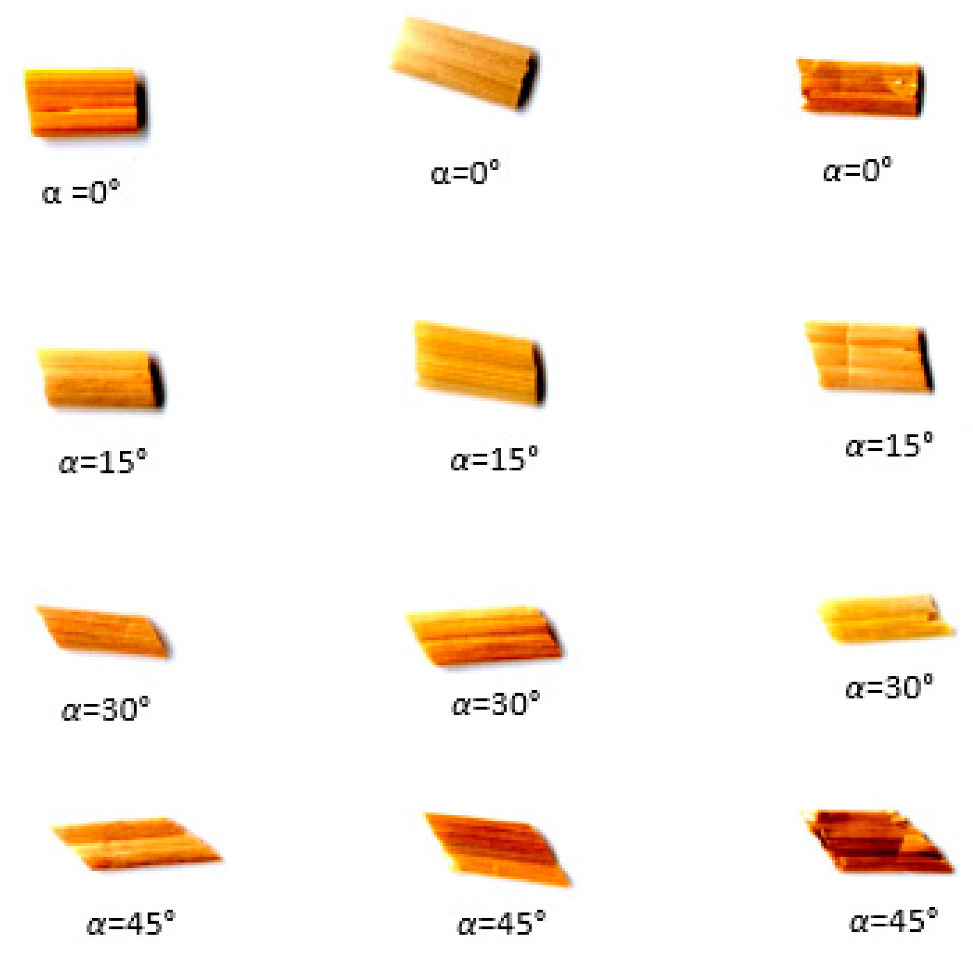
Figure 10 presents the exemplary photographs of cut pieces of plant material (chaff) at different cutting angles α. A detailed analysis of chaff makes it possible to establish that the change of the cutting angle α has an impact on the chaff’s shape and its length. The conducted measurements of the real chaff’s length have proved that it is from 8% to 13% shorter than what results from theoretical calculations.


