Article

Assessment Methodology of Practical Configuration Management (CM) for Sustainable Nuclear Power Plants (NPPs)

1
Land and Housing Institute (LHI), Daejeon 34047, Korea
2
College of Architecture, Myongji University, Yongin 17058, Korea
*
Author to whom correspondence should be addressed.
Sustainability 2019, 11(8), 2391; https://doi.org/10.3390/su11082391
Submission received: 16 January 2019 / Revised: 8 April 2019 / Accepted: 19 April 2019 / Published: 22 April 2019

Abstract

:
Since the Fukushima accident in 2011, nuclear safety has emerged as a very important political and social issue. Under this circumstance, the importance of configuration management (CM) is emphasized in order to ensure the reliability and safety of facility. However, configuration management (CM) is still in its conceptual stage in the nuclear industry due to the ambiguity of CM definitions, insufficiency of CM procedures, paucity of computerized systems and lack of CM professionals. In an attempt to address this issue, a previous study proposed a comprehensive CM framework for nuclear power plants (NPPs) by comparing CM concepts in seven different industries where the CM is actively utilized. In order to facilitate the practical implementation of the conceptual framework, this paper proposes an assessment methodology for prioritizing the importance of CM application areas based on the physical subjects of NPP structures, systems, components (SSCs). The proposed methodology is composed of an ‘extended CM framework’ with further details and ‘evaluation criteria’ based on CM functions. This study developed an SSCs list by analyzing Design Control Document (DCD) of Westinghouse AP1000 and also identified evaluation criteria through an extensive literature review. The concept of CM in this study encompasses the entire NPP project life-cycle in order to promote the practical CM application. The results of case-study performed in this paper would provide the SSCs priorities and guidelines for practical configuration management (CM) for sustainable NPP facilities.

1. Introduction

Nuclear power has drawn attention as an eco-friendly energy source, to respond to the issue of environment pollution problems caused by the indiscreet development and depletion of petroleum resources. However, since the Chernobyl accident in 1986 and the Fukushima accident in 2011, nuclear power safety has become an important political and social issue. Accordingly, the efforts to ensure the safety and reliability of nuclear power plants (NPPs) have been continuously made. As one such effort, the importance of configuration management [1] has been emphasized.
The concept of configuration management (CM) began by the US Department of Defense in the 1950s [2]. The CM for nuclear power plants (NPPs) is generally defined as a process of ‘establishing technical specifics and maintaining their consistency’ between the ‘design requirement, physical configuration and facility configuration information (FCI)’ of the extremely large number of NPP elements those are generally categorized into three groups including ‘structures, systems and components (SSCs)’ [3,4,5,6]. However, the processes and procedures for practical configuration management (CM) implementation are not well developed [3] and the concept of CM is not clear yet in the industry [1]. For these reasons, the CM application to actual business is quite limited [7].
Every single constituent of CM is important to ensure nuclear power plant (NPP) facility safety. However, understanding the most influential areas of NPP CM with high-priority would effectively facilitate practical implementation, especially in the early phase of NPP CM planning. In this aspect, the purpose of this study is to propose a methodology for assessing the relative importance of CM implementation based on ‘structures, systems and components (SSCs)’ elements for effective NPP CM applications. An extended CM framework was defined first based on the previous research of the authors [7]. The physical ‘elements’ and managerial ‘functions’ were also developed in this extended framework. The quantifiable criteria for evaluating ‘elements and functions’ were then identified in this study. Finally, based on these assessment elements and criteria, a methodology of assessing CM importance was proposed. The proposed methodology was validated by a case-evaluation with expert interviews to examine its practicability. Suggestions, implications and lessons-learned from the interviews were summarized as well.

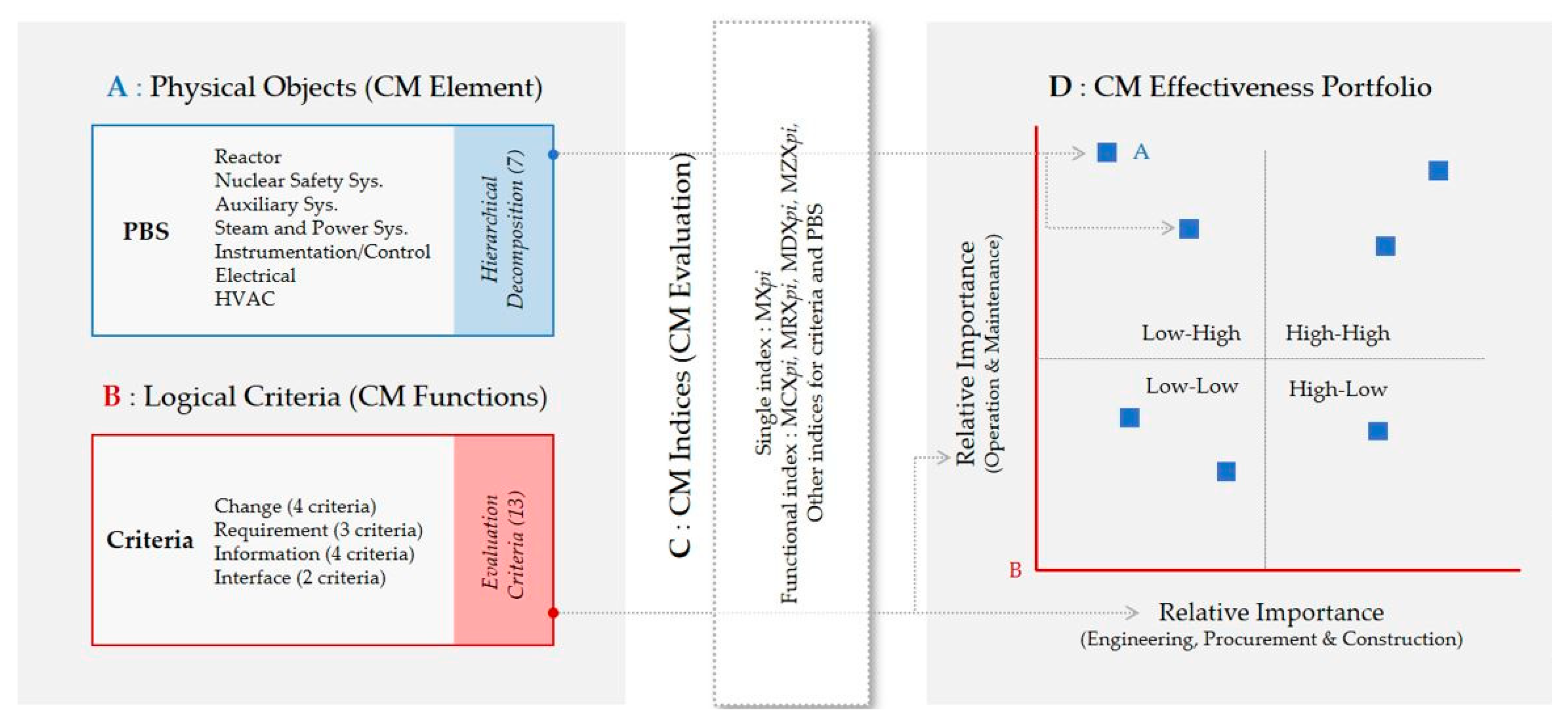
2. Framework for Configuration Management Assessment

As noted, the concept of configuration management (CM) was introduced by the US Department of Defense (DoD) and was used in the defense and aerospace industries in the 1950s [2].
Research and development efforts for CM in other industry sectors have been focused primarily on production control and software development thereafter. It was in the 1990s that the CM implementation of the construction industry including nuclear power plant (NPP) was utilized [7]. ISO 9000 and ISO 10007 also standardized the fundamentals and guidelines of configuration management (CM) in terms of quality management perspective to all industry sectors.
The CM for nuclear power plant (NPP) projects specified the distinct characteristics of NPP elements of ‘structures, systems and components (SSCs)’ in various technical documents for industrial practice [3,4,5,6]. Nevertheless, owing to paucity of academic literature in configuration management (CM) for nuclear power plant (NPP), there is no shared understanding in defining the CM for NPP.
In order to address this issue, Kang and Jung [7] explored different concepts and variables of configuration management (CM) in six different industry sectors including the defense, aerospace, software development, engineering, construction and nuclear industries. Based on the extensive literature review and expert interviews, a previous research by Kang and Jung [7] defined a CM framework for nuclear power plants (NPPs). Their definition expanded the conventional CM concept into the entire facility life-cycle so as to newly refine it in the nuclear power industry. In this paper, each variable of the CM framework by Kang and Jung [7] is extended and substantiated as outlined in Figure 1. This extended CM framework is to be applied as the basic variables of the proposed CM assessment methodology.
In summary, the assessment of configuration management (CM) for NPP in this study is defined as the process of ‘quantifying and prioritizing the effectiveness of CM implementation by evaluating managerial issues of CM functions based on each physical element in order to enhance NPP safety and sustainability throughout the entire facility life-cycle’.
As outlined in Table 1, two major variables of the proposed CM assessment methodology are ‘CM elements’ and ‘CM functions’. The quantifiable measures for CM functions are developed in this study as the assessment criteria. A set of top-down physical breakdown structure (PBS) of ‘CM elements’ is also developed as the units to be evaluated. This top-down structure facilitates accommodating entire elements in many different levels based on different planning and controlling purposes. Details will be further discussed in the later sections of this paper. Section 3 of this paper illustrates the physical objects (i.e., ‘element’ or ‘property’) and Section 4 defines evaluation criteria based on managerial issues of CM ‘functions’. The proposed methodology with a case-study, implications and findings and conclusions will follow in the Section 5 and Section 6, respectively.

2.1. Variables of CM Assessment Framework

The above definition of the CM assessment in this paper is structured with five variables as depicted in Figure 1 and Table 1. The first variable of the CM framework in this study defines the objectives in the top priority: the safety and sustainability of nuclear facilities as shown in the ‘CM Objective’ of Figure 1. The second one is entire life-cycle of a nuclear power plant, which is comprised of seven phases: planning, engineering, procurement, construction, commissioning, operation and decommissioning (‘Lifecycle’ in Figure 1). The third variable of the proposed framework is the CM management technique as depicted in the ‘CM Function’ of Figure 1.
The fourth one specifies the ‘CM elements’ which are classified into structures, systems and components (EPRI 2011). The last one is ‘CM properties’ those include “design requirements, physical configuration and facility configuration information” [3,4,6].
The first three variables (i.e., objectives, life-cycle and functions) of the proposed framework in Table 1 characterize managerial issues and logical concerns, while the next two variables of ‘elements’ and ‘properties’ define physical objects to be managed by the CM processes.

2.2. Outline of CM Assessment Methodology

The CM assessment methodology proposed in this study evaluates seven physical elements of physical breakdown structure (PBS) Level I by using thirteen criteria as depicted in Figure 2. The seven physical elements include ‘reactor, nuclear safety system, auxiliary system, steam and power conversion system, instrumentation and control system, electrical power system and HVAC system’ as listed in the blue Box A of Figure 1. Further details of the physical elements are discussed in Section 3. The thirteen evaluation criteria in the red Box B of Figure 2 were developed based on the first group of variables (i.e., objectives, life-cycle and functions) in Table 1.
Each physical element (e.g., reactor) is evaluated by using thirteen evaluation criteria and the sores for these thirteen criteria are summed up into four functions. In turn, a single index score is yielded by adding all the scores from the four CM functions (Box C in Figure 2).
In the proposed process of evaluating each physical element (e.g., reactor), it is evaluated from two different perspectives; one from the engineering/procurement/construction (EPC) perspective as well as from the operation/maintenance (O&M) perspective. This is due to the fact that an EPC process may have different characteristics to those of the O&M process in terms of evaluation criteria (e.g., complexity of change procedures). The horizontal axis of ‘effectiveness portfolio’, as shown in the Part D of Figure 2, indicates the single index score from ‘EPC’ and the vertical axis presents the single index score for ‘O&M’ so that two different perspectives can be graphically compared.
As the CM effectiveness portfolio has four quadrants with a scale of relative importance, it facilitates to easily locate the most important elements with relatively high scores from both ‘EPC (x-axis)’ and ‘O&M (y-axis)’. It is also possible to decompose one quadrant into sub-quadrants within the high-high quadrant in order to focus on highly impacting elements. Detailed definitions and methods will be elaborated in the following sections with a case-study.

3. Elements for CM Assessment: Structure, System, Component (SSC)

The physical elements of a facility are often used as scoping units to be managed in many project management practices including cost and time management. One of the good examples of practical applications is the ‘physical breakdown structure (PBS)’. PBS can be defined a hierarchically organized set of physical components that supports automated classifying and integrating mechanisms for managerial purposes [8,9,10]. More often than not, the PBS also encompasses high-level functions and administration components in order to incorporate all aspects of project deliverables [9]. However, this study only focuses on physical elements defined in Table 1 because the objectives of NPP CM evaluation is to enhance NPP safety and sustainability.
As discussed, the “structures, systems and components (SSCs)” are used in this study as the physical ‘elements’ to be evaluated in terms of relative importance in NPP CM. The SSCs as evaluation elements can be organized in different hierarchical representations depending on different types of nuclear power plants as well as by virtue of different managerial requirements.

3.1. Element Facets for Classification

A wide range of literature review and expert interviews was performed to find practical classifications for NPP SSC lists. Based on this search, this study selected AP1000 model of Westinghouse [11] for case-study elements, which is one of the nuclear power plant types those approved for Standard Design Certification (SDC) and Combined Operation License (COL) from the Nuclear Regulatory Commission (NRC). Design Control Document [11] of AP1000 was then analyzed so as to reorganize SSCs items for this study, especially considering the comprehensiveness without omissions. Table 2 lists the first level items and their breakdowns.
As shown in Table 2, AP1000 ‘structure’ has 8 items in the first level. The table shows the classification of facilities for a nuclear power plant from the perspective of pure physical breakdown such as reactor building, containment vessel, turbine building and so on. As for ‘system’, AP1000 model 7 items in the first level and 85 items for the second level. The classification of ‘system’ is defined based on the combination of equipment and connecting systems based on the same functionality. Note that a full description of breakdown items of the seven ‘systems’ is listed in Appendix A of this paper. Finally, regarding the ‘component’ of AP1000, the model consists of 2257 components primarily in terms of equipment. This classification facet can be understood from the perspective of equipment breakdown structure (EBS) based on the above 7 ‘systems’.
The three facets of the physical elements of the SSCs, namely the ‘structure’, ‘system’ and ‘component’, are independent of each other so that one facet can complement the other to describe the physical elements of the NPP. Therefore, this study selected the facet of ‘system’ from SSC as the representing element classification for the purpose of NPP CM evaluation.

3.2. Combined NPP SSCs as an Evaluation PBS

Physical breakdown structure (PBS) for CM assessment in this study uses a combined SSCs with a three-level hierarchy. As described in Table 3, the first level of physical breakdown structure (PBS) is comprised of seven elements: “reactor, nuclear safety system, auxiliary system, steam and power conversion system, instrumentation and control system, electrical power system and HVAC system.” These seven major elements represent the two facets of ‘systems’ and ‘components’ together.
The second level of PBS combines the facets of ‘systems’ and ‘structures’. For example, ‘reactor’ as a Level I element has three sub-systems (i.e., FHS; fuel handling and refueling system, RCS; reactor coolant system, RXS; reactor system) and one structures (i.e., nuclear island). The ‘nuclear island’ serves as an infrastructure for three sub-systems of FHS, RCS and RXS. Nevertheless, this ‘nuclear island’ structure should be managed separately for the CM purposes. In this way, the eight elements of ‘structure’ in Table 2 are allocated to Level I elements where each structure is subordinate to.
Finally, the Level III is only composed of the facet of ‘component’. Basically, the components are equipment required for the sub-systems. A total number of 2257 components are defined based on AP1000 DCD.
Accordingly, structures, systems and components (SSCs) of the AP1000 model—which are physical elements of CM evaluation in this study—can be presented with combinations of independent three facets of SSCs. It is noteworthy that a particular component can be used in multiple systems and a particular system can be installed through multiple structures.
From the perspective of managers, it was found to be more efficient to combine many different facets together in an upper level management practice [9]. For these reasons, this study developed a PBS for CM assessment by combining three different facets of SSCs together. However, detailed CM evaluation results at the Level II or III can be easily totaled or journalized with the use of the associative relationship between SSCs. For example, evaluation scores for equipment only can be reported by using the hierarchy of equipment breakdown structure (EBS). In other words, regardless of the PBS, each SSC classification can be used as a different facet to analyze the evaluation results.
Another benefit from using this top-down hierarchy is that the CM assessment can be performed at different levels for different details. For a CM planning purpose, Level I assessment will serve as an effective starting point and further Level II or III evaluation would provide with decisions and information for detail CM systems development.

4. Criteria for CM Assessment: Change, Requirement, Information, Interface

The research by Kang and Jung [7] defined four functions of NPP CM implementation, which include change management, requirement management, information management and interface management as listed in Table 4. Based on these four CM functions, this study developed thirteen evaluation criteria to assess CM activities in terms of relative importance (Table 5).

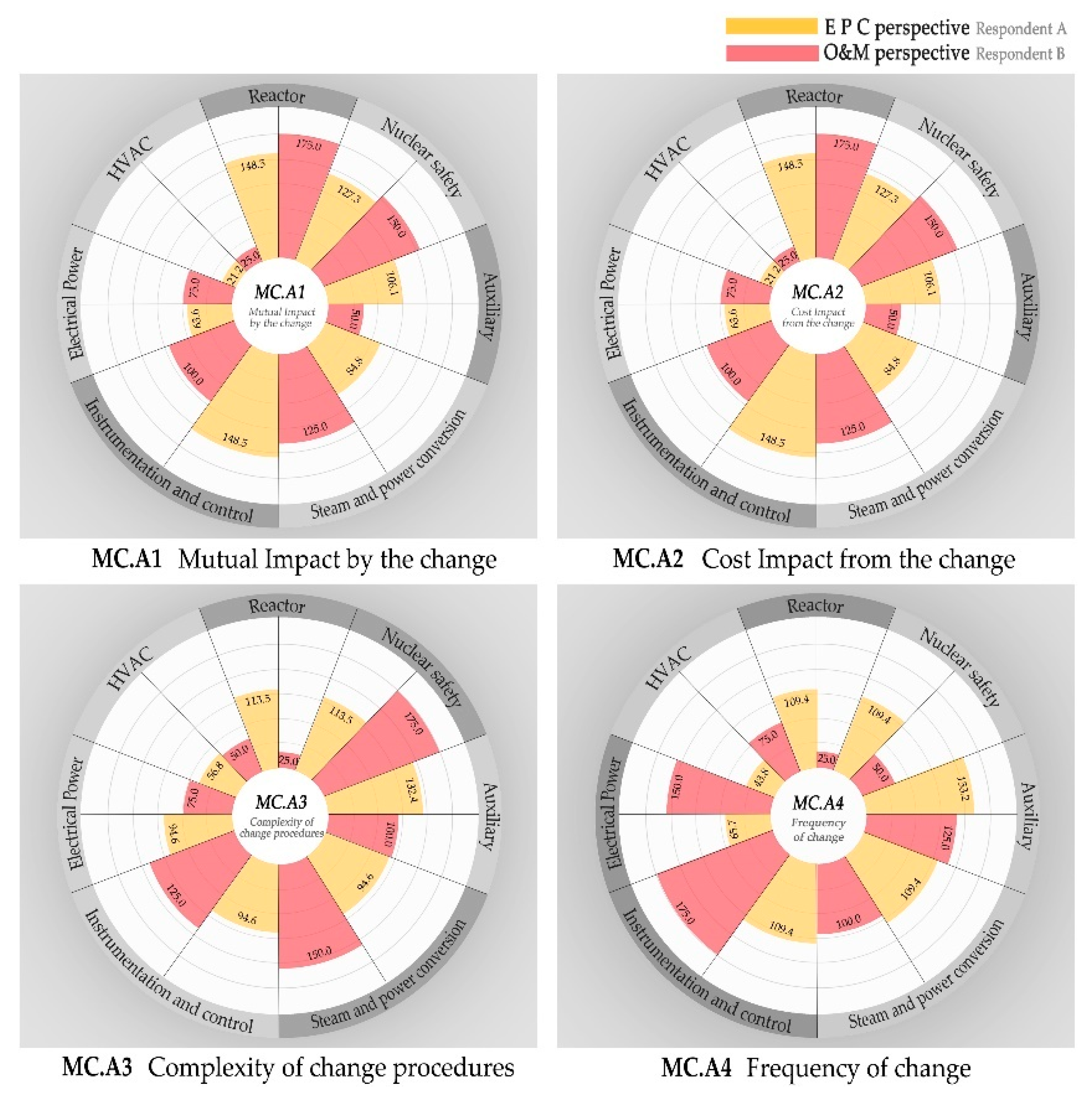
4.1. Evaluation Criteria of Change Management (MC)

As identified in previous study of the authors in Table 4, the objective of change management (MC) is to maintain the conformance between three elements of SSCs (MC1). Therefore, it is required to analyze and document the expected changes (MC2) in terms of on safety, regulations and economy (MC3). The safety and risk assessments for expected changes (MC4) are also performed. The change alternatives and requests are controlled based on these safety and risk assessments in a traceable manner (MC5), working with integrated cost and schedule control system (MC6) as well. Based on this change management (MC) concept, this study developed four assessment criteria including ‘mutual impact by the change (MC.A1)’, ‘cost impact from the change (MC.A2)’, ‘complexity of change procedures (MC.A3)’ and ‘frequency of modification (MC.A4)’.
Firstly, the ‘mutual impact by the change (MC.A1)’ means the degree of a mutual change occurring between three CM properties (i.e., design requirement, physical configuration and facility configuration information) when a system changes. For example, when a part is replaced by engineering changes or by a failure, damage or performance degradation during operation period, it is required to check that technical and physical features of SSCs in the design requirement. Relatively higher degree of a mutual change made between design requirement, physical configuration and facility configuration information means importance of change management in the CM.
Secondly, it is required to comprehensively analyze the cost variation caused by a change along with associated schedule activities in the CM for NPP [6]. The ‘cost impact from the change (MC.A2)’ in this study indicates the relative intensity of monetary influence caused by a change.
The third criterion for the CM function of change management is the ‘complexity of change procedures (MC.A3)’. Whenever any changes are made in the CM for NPPs, it is required to review the information of safety, regulation, maintenance and waste treatment requirements in order to identify risk factors for each alternative and then evaluate the likelihood, impact and cost of the risks by following the process of Probabilistic Safety Assessment (PSA) and Probabilistic Risk Assessment (PRA) [3,12]. Accordingly, MC.A3 in this paper represents the complexity of processes in reviewing the regulations and permits and also the complicatedness of PSA and PRA of a change.
Lastly, the ‘frequency of changes (MC.A4)’ represents the expected frequency of changes based on previous experiences as well as the characteristic of each system for design changes, safety standard changes and periodic safety review [3].

4.2. Evaluation Criteria of Requirement Management (MR)

The requirement management for NPP CM can be summarized as ensuring “documentation and conformance with the NPP requirements from regulations and permits (MR1 in Table 4), industry standards (MR2), PRA/PSA (MR3), owners (MR4), design documents (MR5) and tolerances (MR6)” as listed in Table 4 [7]. Based on this concept, this paper defines three criteria for assessing NPP CM in terms of requirement management (MR). Three criteria are the comparative magnitude of ‘number of specifications (MR.A1), relevance to the capability by design bases (MR.A2) and safety impact caused by the non-conformance between SSC (MR.A3)’.
The first criterion is the number of specifications (MR.A1) to consider in terms of power plant engineering, equipment production, installation, commissioning and operation. For instance, it includes thermal output, pressure, temperature, flow rate, capacity and output speed which should be managed and maintained within the design base values initially set in the operation phase.
The relevance of the capability of design bases (MR.A2) represents the pertinence of safety performance requirements defined in 10CFR50.2. According to the US CM regulation ’10CFR50.2’ [18], the top-level concept of design requirement is the design basis which consists of “design bases functions” and “design bases values.” Requirement management for nuclear power plants is to maintain these design bases functions and design bases values through the entire life-cycle. The safety performance function is defined in three types: “integrity of the reactor coolant pressure boundary,” “capability to shut down the reactor and maintain it in a safe-shutdown condition” and “capability to prevent or mitigate the consequences of accidents that could result in potential offsite exposures that are comparable to the requirements in 10CFR50.34(a)(1).” In this sense, MR.A2 represents how each NPP elements is closely related to the ‘capability by design bases’.
As the third criterion in MR, the ‘safety impact caused by the non-conformance between SSC’ (MR.A3) means safety influence on the entire power plant when the inconsistency between documents, configurations and requirements is caused by engineering change or human errors.

4.3. Evaluation Criteria of Information Management (MD)

Information management (MD) in NPP CM is an essential area for improving efficiency of data manipulation under the extremely huge and complex computing environment. Kang and Jung [7] stresses that NPP CM information management stands in need of a well-organized “engineering document management system (MD3 in Table 4)” that integrates the entire NPP life cycle (MD1) information in an easily traceable manner (MD4) with the supports from an effective numbering system (MD2) as well as a version management system (MD5). It also requires a capability of “reconstitution of design documents (MD6)” based on the priority evaluation of datasets.
In order to assess the relative importance of CM implementation in terms of the information management (MD), four criteria including ‘complexity of the elements (SSCs) (MD.A1), quantity of documents (MD.A2), frequency of document retrieval (MD.A3) and importance of document in O & M phase (MD.A4)’ were identified in this study.
When a system is changed, it is very important to track it is all relevant documents those should be changed accordingly. It is required to establish a document management system by IAEA [3] in order to manage the history of all versions and revisions of documents, to perform interface management of SSCs information and to track changes. In this sense, the complexity of structures, systems and components (SSCs) (MD.A1) and quantity of documents (MD.A2) are relating to the management level of details for CM implementation. The MD.A1 was evaluated on the basis of the number of components of each system in AP1000.
The frequency of document retrieval (MD.A3) is the factor to evaluate the frequency of data usage for each system. The higher frequency indicates the higher importance of information management for a specific system.
In the information management for nuclear power plant CM, it is very important to efficiently manage ‘design bases and license bases’ information from the initial engineering phase. One of the purposes of the information management is to handover a variety of information to the operation phase [19]. Such information can be used as training materials, inspection manuals or the reference data for decision-making at an operation failure or accident. Accordingly, as the last evaluation criterion, the importance of document in O & M phase (MD.A4) was selected.

4.4. Evaluation Criteria of Interface Management (MI)

In order to systematically manage the interfaces among many different participants and many different work packages in a mega-project, critical interfaces and boundaries need to be identified first.
Therefore, it is necessary to classify the participating organizations and their key roles based on project life-cycle phases as well as assigned work packages [3,6] so that boundaries and interfaces between activities, influenced organizations and shared information can be appropriately controlled in the business process [3]. In other words, the CM interface management (MI) should define and control the interfaces between organizations (MI1), processes (MI2) and activity information (MI3).
As listed in Table 5, in order to quantify the effectiveness in interface management, this study defined two criteria of CM evaluation for interface management. The first one is required manpower (MI.A1) and another is the number of related activities in the interfaces (MI.A2).

5. Assessment Methodology and a Case Study

Based on the NPP CM assessment ‘elements’ and ‘criteria’ defined in Section 3 and Section 4, this study proposes a methodology for evaluating the relative importance of each ‘element’ based on thirteen ‘criteria’ for nuclear power plants. Suggestions, implications and lessons-learned from the case-assessment were briefly summarized as well.

5.1. NPP CM Evaluation Methodology

As briefly outlined in Figure 2, the proposed NPP CM assessment methodology has four major parts, which include CM elements (Part A in Figure 2), CM criteria (Part B), CM indices (Part C) and a CM effectiveness portfolio (Part D). Note that a glossary of terms is listed in Appendix C.
Part A, the CM elements as the objects of the evaluation in Table 3, has a three level hierarchy of physical breakdown structure (PBS). The first level has seven physical elements as listed in Table 3 and the blue Box A of Figure 2. The seven elements in the first level is then decomposed into 97 elements in the second level of PBS, which include twelve elements from the ‘structure’ facet and 85 elements from the ‘system’ facet as listed in Table 3. Finally, the third level of PBS has 2,257 equipment items from the ‘components’ facet. Note that the relationship from Level I to Level II is one-to-one type, while that between Level II and level III is many-to-many type in terms of database cardinality. This is the due to the fact that one equipment can be part of a second level ‘system’ as well as a ‘structure’.
Part B—the CM criteria for evaluating the CM elements—has thirteen criteria in terms of ‘change, requirement, information and interface’ management for NPP CM as defined in Section 4 and Table 5. Among this thirteen criteria, four criteria focus on the impact from the configuration management (CM) including cost impact from the change (MC.A2), relevance to the capacity by design bases (MR.A2), safety impact caused by the non-conformance between SSC (MR.A3) and importance of document in the O&M phase (MD.A4). Three (MC.A1, MD.A2, MI.A1), two (MC.A3, MD.A1) and four (MC.A3, MR.A1, MD.A3, MI.A2) criteria represent ‘workload’, ‘complexity’ and ‘frequency’ of the NPP CM functions, respectively. All criteria except ‘required manpower (MI.A1)’ use 7-point scale to quantify relative importance among the CM elements, as listed in Table 6. MI.A1 is evaluated by estimating percentage of required manpower for a specific element among all CM elements.
In Part C, CM indices of each CM element in the first level of PBS is evaluated for four different CM functions (MC, MR, MD and MI), by using the corresponding criteria those are subordinate to the same function group. In order to compare the different perspectives from engineering/procurement/construction (EPC, respondent group A) and operation/maintenance (respondent group B) phases, the methodology performs the same evaluation with two different groups within the same organization. This is due to the fact that CM characteristics of a construction process may be different from those of the operation process in terms of evaluation criteria (e.g., complexity of change procedures).
For an example of the assessment from a respondent ‘A (one from EPC)’ for ‘change management (MC)’ as illustrated in Table 7, each of seven CM elements are firstly evaluated for four MC criteria (MC.A1~MC.A4) by using a seven-point Likert scale.
A ‘comparative score’ of an element (e.g., p1: reactor) in terms of one criteria (e.g., MC.A1) can be yielded by dividing the Likert-scale score of p1 by total score of seven elements for MC.A1. In order to normalize the scores among the seven elements, 700 (100 ∗ n, where n is the number of elements) is multiplied to the ‘comparative score’. The Formula 1 (F1) in Table 7 shows this equation (MC.A1.Ap1 = (MC.A1.Ap1)/∑(MC.A1.Api) ∗ 100 ∗ n). The notations of ‘MC.A1’, ‘A’, ‘p1’ and ‘n’ indicate the criterion of ‘mutual impact by the change (MC.A1)’, respondent ‘A’, element of ‘reactor’ (p1) and the number of elements (n). This normalized score facilitates easier comparison as the score of 100 is the exact average and median.
After repeating this calculation for four MC criteria (MC.A1~MC.A4), a normalized average score of p1 for MC (MC.Ap1 in F2 in Table 7) can be represented in a percentile score format, for example, which is 130.0 as shown in the sixth row under the title of ‘Reactor (p1)’ in Table 8.
Finally, a single index by averaging four scores from the four CM functions (MC, MR, MD and MI) indicates the relative importance of one specific element. For example, single index for reactor from the engineering/procurement/construction (EPC) perspective (M.Ap1) is 126.5 in Table 8 and Figure 3.
Part D visualizes the evaluation results in a portfolio as depicted in Figure 2 as well as Figure 3 and Figure 4. The horizontal axis of ‘effectiveness portfolio’ indicates the single index score of each element in terms of ‘EPC (A)’ effectiveness and the vertical axis presents the single index score from the ‘O&M (B)’ perspective. It is possible to decompose one quadrants into sub-quadrants within the high-high area in order to focus on highly impacting elements.
It also facilitates the decomposition of the PBS elements into the second level when a detailed evaluation is necessary. With the assessment results in the second level of PBS, the portfolio can depict the CM effectiveness from the ‘structure’ facet as well. By analyzing in this manner, the proposed methodology enables embedding the engineers’ experience and knowledge into a system in a structured way to analyze CM importance and priority.

5.2. Overview of a Case Assessment

As described in the introduction, the comprehensive CM for nuclear power plants is practiced by a very limited number of experienced experts. Accordingly, there are very few experts who can quantify all evaluation criteria developed in this study. Furthermore, there is a very limited number of managers who have practical knowledge and experience across the entire project life-cycle ranging from engineering/procurement/construction (EPC) through operation/maintenance (O&M) of nuclear power plants. It was also prohibited for the authors to access to confidential information of existing NPP facilities.
Because of these limitations, this study conducted an expert workshop by using a structured questionnaire based on the NPP CM evaluation criteria. Two experts, who are knowledgeable about the overall NPP life-cycle issues of the configuration management (CM) practice, participated in this workshop. The first expert, who responded from an engineering perspective /procurement/construction (A in the Table 7 and Table 8), has a thirty-year career specialized in the NPP construction and commissioning. Another expert (B) is a specialized manager with thirteen years of experience in NPP operation. These two experts are from the same organization, which is a Korean public owner/operator of more than twenty NPP facilities. These two experts, in the position of general or deputy managers, are invited to take part in this study based on their comprehensive managerial experience of the planning, engineering, procurement, startup and operation of many nuclear power plants as well as their current efforts in developing NPP configuration management system.
The case-study evaluation in this paper was conducted at the first level of NPP PBS with seven CM elements due to the limited availability of the experts as well as the confidentiality of the NPP information. If the methodology is utilized for an in-house assessment for a specific NPP with internally available simple information and data, the accuracy and implications of the evaluation result will have a significant value as a starting point for further practical implementation. Even with this limited information, the case-study in this paper could draw important findings owing to the highly experienced experts’ participation.
The overall scores (M.Tpi in Table 8) from this case-assessment show that the most important three areas for effective CM implementation are in the order of ‘nuclear safety’ system (M.Tp2 = 129.5), ‘reactor’ (M.Tp1 = 125.8) and ‘instrumentation and control (I&C)’ system (M.Tp2 = 112.2). While the reactor (p1) and I&C (p5) have similar scores from the respondent A and B (M.|AB|p1 = 1.5, M.|AB|p5 = 2.6), the ‘nuclear safety’ (p2) has somewhat different scores from two respondents (M.|AB|p2 = 10.9).
The ‘auxiliary’ system (M.|AB|p3 = 38.2) shows the most considerable difference between respondent A and B. It is interpreted that CM is relatively more effective in EPC phase (respondent A) than in O&M (respondent B) phase. This fact is due to the complex nature of the auxiliary system, as shown in PBS Level II in Table 3, requiring complicated activities in the EPC phase. As such, the different perspectives between EPC and O&M for different CM elements are interestingly revealed by the case-assessment.

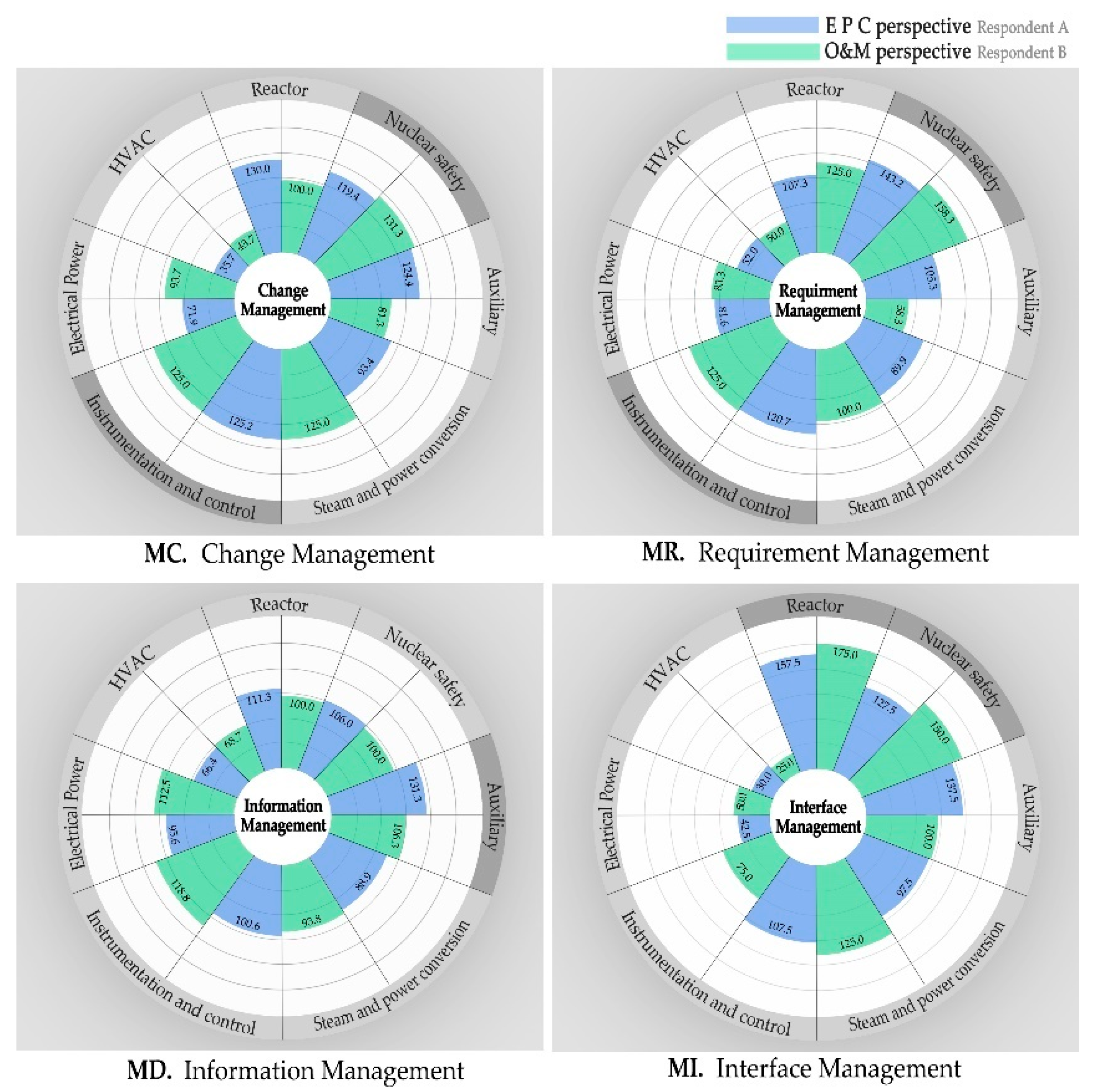
5.3. Assessment Result of Change Management Function (MC)

The first level evaluation with the single index score, represented by using the notation of M.Xpi in Formula 3 (F3) of Table 7, was introduced in the previous section. When it is decomposed into the CM function level, the first assessment issue is the degree of relative effectiveness from the view point of change management (MC) function (MC.Xpi in Formula 2 (F2) of Table 7) as depicted in Figure 5.
It was found to be in the order of ‘nuclear safety’ system (p2), ‘instrumentation and control (I&C)’ system (p5) and ‘reactor’ (p1) as being the three most important elements. Total scores of these three elements (MC.Tp2, MC.Tp5, MC.Tp1) are 125.3, 125.1 and 115.0, respectively, as shown in Table 8 and Figure 3.
‘Reactor’ (p1) and ‘nuclear safety’ system (p2) are the core systems of NPPs which are playing the most critical role in a nuclear power plant. Therefore, these two element of p1 and p2 has high scores from both respondents (MC.Ap1 = 130.0, MC.Ap2 = 119.4, MC.Bp1 = 100.0, MC.Bp2 = 131.3) as depicted in Figure 4 and Figure 5. The element of ‘I&C’ (p5) system has also a high score (MC.Ap5 = 125.2, MC.Bp5 = 125.0) as it has tremendous and complicated inter-relationships with other elements. As discussed, the distinct characteristics of each group as well as life-cycle perspective were represented by the evaluation.
As for the life-cycle perspective, two different respondents, A (EPC) and B (O&M), have different scores for some elements. Respondent B stresses the importance of ‘steam and power conversion’ (p4) because it is used to supply power to the entire power plant during the O&M phase and the respondent A outscored ‘auxiliary’ system as it has complex inter-relationships between many connected sub-elements in terms of EPC processes. More implications from this evaluation were observed in the lowest level indices. The scores by each CM criterion is listed in Appendix B and Figure 6.
For example, under the ‘mutual impact by the change’ (MC.A1) criterion, EPC respondent chose the ‘I&C’ (MC.A1.Ap5 = 148.5), while O&M respondent selected the ‘reactor’ (MC.A1.Bp1 = 175.0) as the most important element.
In terms of ‘complexity of change procedures’ (MC.A3), the ‘auxiliary’ system (MC.A3.Ap3 = 132.4) has the highest score for EPC. In the nuclear power industry, the procurement of major components is generally made in the early project stage, whereas that of auxiliary components is sequentially contracted in line with a plan. As opposed to the major components, auxiliary components involve complicated participation by multiple firms [20]. This fact makes the change procedure very complex, especially in the EPC phase.
Another interesting thing is the highest score of ‘I&C’ for ‘frequency of changes’ in the O&M phase (MC.A4.Bp5 = 175.0). I&C system automatically detects neutron measure, temperature measure, heat measure, a replacement cycle of nuclear fuel. Therefore, components and parts are frequently replaced for the reason of radiation-induced material deterioration.
In terms of MC.A4. criterion, the EPC respondent (A) had remarkably higher scores for ‘frequency of changes’ of ‘reactor’ and ‘nuclear safety’ system than the O& M respondent (B). That is because the EPC phase of a nuclear power plant is highly influenced by requirement change in various laws and licenses related to the two systems with high safety importance and thereby has more frequent modifications than in the O&M phase. The commissioning phase before the operation of a nuclear power plant is the final stage [21] to check if a nuclear power plant perfectly meets design and safety requirements defined in the safety assessment report and permits in order for running a nuclear reactor and to check if SSCs of a nuclear power plant execute their functions properly just as described in engineering documents. For this reason, the O&M respondent had relatively lower scores of ‘frequency of changes’ for ‘reactor’ and ‘nuclear safety’.

5.4. Assessment Result of Requirement Management Function (MR)

The overall result from the requirement management (MR) assessment shows that the three important elements are in the order of ‘nuclear safety’ system (p2), ‘instrumentation and control (I&C)’ system (p5) and ‘reactor’ (p1) where the scores (MR.Tp2, MR.Tp5, MR.Tp1) are 150.8, 122.9 and 116.2, respectively, as shown in Table 8 and Figure 4. The spider charts for scores of each criterion for MR, MD, MI are listed in Appendix B but not included in this paper for the sake of editorial conciseness.
The result from MR.A1 (number of specifications) analysis has the same score for each element regardless of respondent A or B. The number of specifications was high in the order of ‘nuclear safety’, ‘I&C’ and ‘auxiliary’ system. The ‘nuclear safety’ system prevents a nuclear reactor from an operation halt or leakage of radioactive substances. ‘I&C’ system monitors main safety variables of a nuclear power plant and generates a signal of stopping a nuclear reactor if setup operation values are out of their limits. Therefore, it is important to make thorough requirement management of these systems in order to properly maintain engineering margin and operation margin.
Regarding MR.A2 (relevance to the capability by design bases) and MR.A3 (safety importance of spec. by system), from both EPC and O&M perspectives, importance was commonly high in the order of ‘reactor’ and ‘nuclear safety’ system. That is because these two systems execute core safety functions which could lead to a severe accident if they fail or generate troubles. MR.A3 (safety impact caused by the non-conformance between SSC) evaluation result showed a similar pattern in both respondents A and B.
In the ‘auxiliary’, the scores of MR.A2 (relevance to the capability by design bases) and MR.A3 (safety impact caused by the non-conformance between SSC) were remarkably lower from the O&M perspective (respondent B) than those from the EPC perspective (respondent A). This implication is due to the fact that the overall relative importance of ‘reactor’ and ‘nuclear safety’ were highlighted in these MR.A2 and MR.A3 criteria as shown in Appendix B. In addition, the M&O perspective evaluated the ‘auxiliary’ with relative lower relevance and impact based on characteristics of the operation phase.
The MR evaluation examines a different facet of the CM effectiveness, which is the documentation and conformance with the NPP requirements from regulations and permits. In summary, the ‘nuclear safety’ (p2) far outscored among seven elements. It is also notable that the ‘auxiliary’ (p3) has relatively low score (MR.Tp3 = 81.8) in MR as opposed to the high score in change management (MC.Tp3 = 102.8).

5.5. Assessment Result of Information Management Function (MD)

As for information management (MD), the ‘auxiliary’ system get the highest score (MD.Tp3 = 118.8) with the highest indices from ‘quantity of documents’ (MD.A2.Ap3 = MD.A2.Bp3 = 125.0) and ‘frequency of document retrieval’ (MD.A3.Ap3 = 169.0, MD.A3.Bp3 = 125.0). The same scores for MD.A1 and MD.A2 used for both respondent A and B.
In case of MD.A1 (complexity of the elements in SSCs), the number of components was calculated based on the System Level 1 of AP1000. As a result, the scores of MD.A1 are high in the order of ‘reactor’, ‘nuclear safety’, ‘auxiliary’, ‘HVAC’, ‘electrical power’, ‘steam and power conversion’ and I&C systems.
The result for MD.A2 (quantity of documents) was very different from MD.A1, being high in the order of ‘I&C’, ‘electrical power’, ‘auxiliary’ ‘steam and power conversion’, ‘HVAC’, ‘nuclear safety’ and ‘reactor’. It is found that the ‘I&C’ system has relatively large amount of documents (MD.A2.Tp5 = 175.0) considering its relatively small number of components (MD.A1.Tp5 = 25.0).
The scores for MD.A3 (frequency of document retrieval) have a similar pattern with MD.A2, however, there were some difference between respondent A and B. ‘I&C’ system was evaluated as the most important one (MD.A3.Tp5 = 135.8).
Finally, in the MD.A4 (importance of document in O&M phase), both respondents A and B commonly evaluated that ‘reactor’ and ‘nuclear safety’ system had higher importance.

5.6. Assessment Result of Interface Management Function (MI)

The MI assessment focuses on the ‘required manpower’ (MI.A1) and ‘number of related activities’ (MI.A2) of interface management. Again, the two core systems of ‘reactor’ (MI.Tp1 = 166.3) and ‘nuclear safety’ (MI.Tp2 = 138.8) system were evaluated as being the most important areas. It is interesting that the ‘electrical power’ and ‘HVAC’ gain very low scores in MI assessment (MI.Tp1 = 46.3, MI.Tp1 = 27.5, respectively). It indicates that the score variation between seven element of PBS level 1 has the biggest one in MI assessment. In other words, ‘electrical power’ and ‘HVAC’ are relatively the least important area in terms of interface management.

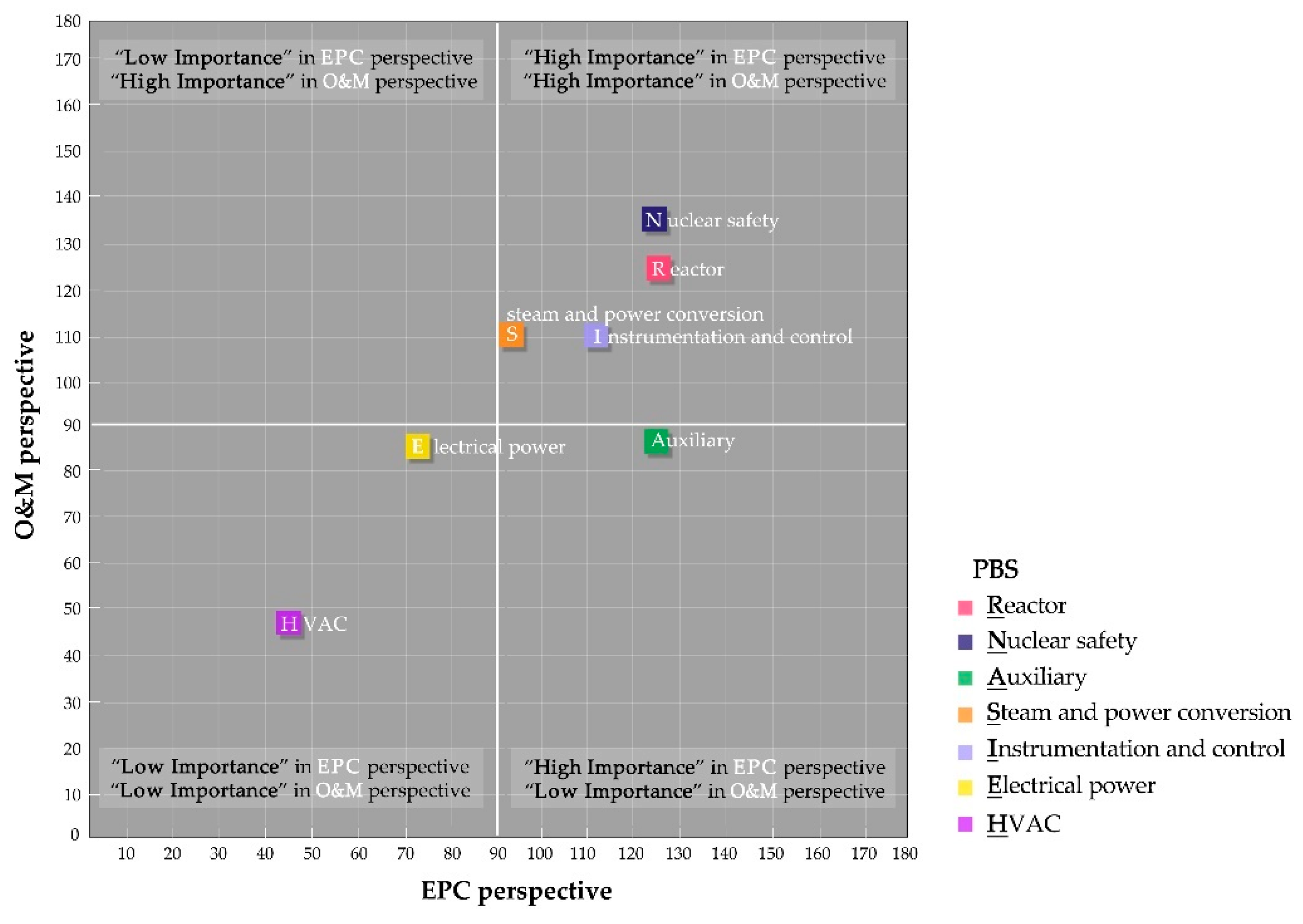
5.7. Summary and Discussions

In summary, based on the single index from the CM case-assessment, the ‘nuclear safety’ system (M.Tp2 = 129.5) and ‘reactor’ (M.Tp1 = 125.8) were evaluated as being the most important elements and the ‘HVAC’ (M.Tp7 = 46.5) and ‘electrical power’ (M.Tp6 = 79.0) systems had the lowest CM importance.
The ‘auxiliary’, ‘I&C’ and ‘steam and power conversion’ were in the range of median scores (105.5, 112.2 and 101.7, respectively). It was interesting that the ‘auxiliary’ system has the biggest gap between EPC and O&M perspectives (M.|AB|p3 = 38.2), because there are differences in methods of business processes and contract requirements depending on systems in a particular life-cycle of nuclear power plants. It means that the auxiliary system is more effective when CM is highly focused during the EPC phase than in the O&M phase. Nevertheless, as depicted in Figure 3, most of the seven element except ‘auxiliary’ are located near a square pitch line, which indicates there has been no big difference between EPC and O&M perspectives.
Figure 3 presents the single index of the CM importance by each system and Figure 4 shows functional indices of change management, requirement management, information management and interface management by each element. In these two portfolio diagrams, the elements located in the second quadrant had relatively high importance both from EPC and O&M perspectives. It is strongly recommended to decompose the second (high-high) quadrant into four sub-quadrants in the second level PBS elements so that the most effective detail elements can be easily identified for practical implementation.
In terms of information management (MD), the ‘auxiliary’ system scored the highest priority (MD.Tp2 = 118.8) and ‘HVAC’ system (MD.Tp7 = 67.9) showed the lowest importance. This result indicates the emphasis of data acquisition and handover requirements for this complex and complicated ‘auxiliary’ system. The authors are currently performing the issues of standardized information exchange of equipment and installation in this aspect as well as associated functionality of the NPP schedule [22] and risk [10] management.

6. Conclusions

The configuration management (CM) is getting recognized as a critical management area to ensure the safety and sustainability of NPP facility. Nevertheless, the practical implementation with an automated system is still in its beginning stage and existing CM literature for nuclear power plants was mostly based on conceptual guidelines. In an attempt to address this issue, this paper proposed a methodology for evaluating CM effectiveness in a top-down manner. The proposed methodology facilitates identifying the most effective areas for CM systems planning and development.
As the evaluation objects of CM effectiveness, a hierarchical physical breakdown system (PBS) structure with decomposing elements was defined and thirteen CM criteria encompassing comprehensive considerations were also developed in this study. Based on the CM elements and criteria, a CM effectiveness portfolio is proposed.
Because of the limitation of available experts in the area of nuclear power plant CM, this paper conducted an expert workshop by using a structured questionnaire. Therefore, the result of case-evaluation has a limitation in terms of statistical power and following studies would better validate the proposed methodology. Instead, this paper focused on developing a comprehensive framework for CM effectiveness assessment that would serve as a descriptive model to integrate relevant concepts and concerns for academia as well as practitioners. Even though it is specific to the case-assessment evaluation of this study, the distinct characteristics of each element (e.g., reactor, nuclear safety and auxiliary system) were identified to provide meaningful implications to the practitioners of nuclear power plant (NPP) CM.
The case-study showed that the two most important areas for NPP CM are ‘nuclear safety’ system and ‘reactor’ in terms of total score of the configuration management effectiveness index. The ‘nuclear safety’ system attained the highest scores in two CM functions among four functions, including ‘change management’ and ‘require management’. Especially, it significantly outscored from the ‘requirement management’ perspective due to the legitimate requirements by various standards, assessments, permits and regulations for NPP safety. The ‘reactor’ scored the second rank in terms of total score of the configuration management effectiveness index, however it was in the first rank from the ‘interface management’ perspective reflecting the complex interfaces between the reactor and others. As for the ‘information management’ perspective, the ‘auxiliary’ systems scored the highest because of its technical characteristics of being consist of many different structures, systems and components (SSCs) as well as requiring a large amount information in terms of complexity, quantity and frequency.
It is also notable that the engineering/procurement/construction (EPC) and operation/ maintenance (O&M) experts have slightly different perspectives in perceiving the CM issues due to the different business focuses. This fact is particularly giving lessons-learned for the ‘auxiliary’ systems to be focused in the EPC phase for better CM readiness.
In order for successful CM implementation, all participants in an NPP project should cooperate to acquire the huge amount of data in an effective and systematic way. In this sense, the standards making for modeling and exchanging NPP information by using neutral protocols and formats is essential. It is expected the international standards development organizations (SDOs) such as International Organization for Standardization (ISO) would also define the vehicles for automated information exchange for NPP CM.
Finally, it is expected for this paper to provide some starting points for developing practical CM planning guidelines in the near future. Further decomposition of the physical breakdown structure (PBS), identification of critical dataset for each element and development of automated measurement methods for the proposed criteria would make the practical configuration management (CM) much more viable. In addition, if the procedures for all of the ‘requirement management, change management, information management, interface management’ as well as procurement management, license and regulations and other kinds are systemized and inter-connected, the effect of CM implementation would be further maximized.

Author Contributions

M.-Y.K. conceived the framework and methodology and performed the case-evaluation through the literature review and expert interviews. Y.J. worked together in conceiving and developing the methodology. M.-Y.K., Y.J. and Y.J. analyzed the data and wrote the paper.

Funding

This study was supported by the Basic Science Research Program through the National Research Foundation of Korea (NRF) funded by the Ministry of Science, ICT (MSIT) under Grant No. NRF-2017R1E1A1A01075786.

Conflicts of Interest

The authors declare no conflict of interest.

Appendix A

Table A1. Breakdown of Systems.
CCS—System Level ISystem Level II
ReactorFHSFuel Handling and Refueling System
RCSReactor Coolant System
RXSReactor System
Nuclear Safety System CNSContainment System
PCSPassive Containment Cooling System
PXSPassive Core Cooling System
SGSSteam Generator System
VESMain Control Room Emergency Habitability System
Auxiliary SystemCCSComponent Cooling Water System
CVSChemical and Volume Control System
DOSStandby Diesel Fuel Oil System
FPSFire Protection System
MHSMechanical Handling System
RNSNormal Residual Heat Removal System
SFSSpent Fuel Pool Cooling System
SWSService Water System
VLSContainment Hydrogen Control System
WLSLiquid Radwaste System
WGSGaseous Radwaste System
WSSSolid Radwaste System
PSSPrimary Sampling System
DWSDemineralized Water Transfer and Storage System
CASCompressed and Instrument Air System
PWSPotable Water System
WWSWaste Water System
PGSPlant Gas System
EFSCommunication System
TCSTurbine Building Closed Cooling Water System
SSSSecondary Sampling System
VUSContainment Leak Rate Test System
DWSDemineralized Water Treatment System
RDSGravity and Roof Drain Collection System
SDSSanitary Drainage System
TDSTurbine Island Vents, Drains and Relief System
WRSRadioactive Waste Drain System
DRSStorm Drain System
RWSRaw Water System
Steam and Power Conversion SystemFWSMain and Startup Feedwater System
MTSMain Turbine System
MSSMain Steam System
BDSSteam Generator Blowdown System
CMSCondenser Air Removal System
CDSCondensate System
CWSCirculating Water System
ASSAuxiliary Steam Supply System
CESCondenser Tube Cleaning System
CFSTurbine Island Chemical Feed System
CPSCondensate Polishing System
GSSGland Seal System
HCSGenerator Hydrogen and CO2 System
HDSHeater Drain System
HSSHydrogen Seal Oil System
LOSMain Turbine and Generator Lube Oil System
Instrumentation and Control SystemDASDiverse Actuation System
PMSProtection and Safety Monitoring System
PLSPlant Control System
DDSData Display and Processing System
IISIn-Core Instrumentation System
SMSSpecial Monitoring System
OCSOperation and Control Centers System
RMSRadiation Monitoring System
SJSSeismic Monitoring System
TOSMain Turbine Control and Diagnostic System
Electrical Power SystemECSMain ac Power System
EDSNon-Class 1E dc and Uninterruptible Power Supply System
IDSClass 1E dc and Uninterruptible Power Supply System
ZOSOnsite Standby Power System
ELSLighting System
EGSGrounding and Lighting Protection System
SHTSpecial Process Heat Tracing System
CAPCathodic Protection System
PSEPlant Security System
ZASMain Generation System
EVRExcitation and Voltage Regulation System
HVAC SystemVBSNuclear Island Nonradioactive Ventilation System
VWSCentral Chilled Water System
VXSAnnex/Auxiliary Building Nonradioactive Ventilation System
VZSDiesel Generator Building Ventilation System
VASRadiologically Controlled Area Ventilation System
VFSContainment Air Filtration System
VCSContainment Recirculation Cooling System
VRSRadwaste Building HVAC System
VHSHealth Physics and Hot Machine Shop HVAC System
VYSHot Water Heating System
VTSTurbine Building Ventilation System
* Based on AP1000 Design Control Document Rev.19 (Westinghouse 2011).

Appendix B

Table A2. Results by Configuration Management Evaluation Criteria.
CM FunctionX *(p1) Reactor(p2) Nuclear Safety(p3) Auxiliary(p4) Steam and Power Conversion(p5) Instrumentation & Control(p6) Electrical Power(p7) HVAC
Change ManagementMC.A1A148.5127.3106.184.8148.563.621.2
B175.0150.050.0125.0100.075.025.0
MC.A2A148.5127.3106.184.8148.563.621.2
B175.0150.050.0125.0100.075.025.0
MC.A3A113.5113.5132.494.694.694.656.8
B25.0175.0100.0150.0125.075.050.0
MC.A4A109.4109.4153.2109.4109.465.743.8
B25.050.0125.0100.0175.0150.075.0
Requirement ManagementMR.A1A25.0175.0125.0100.0150.075.050.0
B25.0175.0125.0100.0150.075.050.0
MR.A2A148.5127.3106.184.8106.184.842.4
B175.0150.025.0125.0100.075.050.0
MR.A3A148.5127.384.884.8106.184.863.6
B175.0150.025.075.0125.0100.050.0
Information ManagementMD.A1A175.0150.0125.050.025.075.0100.0
B175.0150.0125.050.025.075.0100.0
MD.A2A25.050.0125.0100.0175.0150.075.0
B25.050.0125.0100.0175.0150.075.0
MD.A3A96.596.5169.0120.796.572.448.3
B25.050.0125.0100.0175.0150.075.0
MD.A4A148.5127.3106.184.8106.184.842.4
B175.0150.050.0125.0100.075.025.0
Interface ManagementMI.A1A140.0105.0175.070.0140.035.035.0
B175.0150.0100.0125.075.050.025.0
MI.A2A175.0150.0100.0125.075.050.025.0
B175.0150.0100.0125.075.050.025.0
* X: A: Responses from EPC, B: Responses from O&M.

Appendix C. Glossary of Terms

CMConfiguration Management
COLCombined Operation License
DCDDesign Control Document
DoDDepartment of Defense
EBSEquipment Breakdown Structure
EPCEngineering, Procurement, Construction
EPRIElectric Power Research Institute
FCIFacility Configuration Information
IAEAInternational Atomic Energy Agency
INPOInstitute of Nuclear Power Operations
MCEvaluation Criteria for Change Management
MDEvaluation Criteria for Information Management
MIEvaluation Criteria for Interface Management
MREvaluation Criteria for Requirement Management
NPPNuclear Power Plant
NRCNuclear Regulatory Commission
O&MOperation and Maintenance
PBSPhysical Breakdown Structure
PRAProbabilistic Risk Assessment
PSAProbabilistic Safety Assessment
SDCStandard Design Certification
SSCStructures, Systems, Components

References

  1. KINS. Study on Establishment of Regulation Policy for the Reinforcement of Configuration Management and Application in Nuclear Power Plants; Nuclear Safety and Security Commission (NSSC): Seoul, Korea, 2013.
  2. DoD. Configuration Management Guidance; Department of Defense (DoD): Washington, DC, USA, 2001.
  3. IAEA. Configuration Management in Nuclear Power Plants; IAEA: Vienna, Austria, 2003; ISBN 92-0-100503-2. [Google Scholar]
  4. INPO. Configuration Management Process Description; Institute of Nuclear Power Operations (INPO): Atlanta, GA, USA, 2005; AP-929 Revision 1. [Google Scholar]
  5. IAEA. Information Technology for Nuclear Power Plant Configuration Management; IAEA: Vienna, Austria, 2010; ISBN 978-92-0-106310-6. [Google Scholar]
  6. EPRI. Elements of Pre-Operational and Operational Configuration Management for a New Nuclear Facility; EPRI: Palo Alto, CA, USA, 2011; 1022684. [Google Scholar]
  7. Kang, M.-Y.; Jung, Y. Framework & Functions of Configuration Management (CM) in Nuclear Power Plants (NPP). Korean J. Constr. Eng. Manag. 2015, 16, 101–112. [Google Scholar] [Green Version]
  8. Jung, Y.; Woo, S. Flexible Work Breakdown Structure for Integrated Cost and Schedule Control. J. Constr. Eng. Manag. 2004, 130, 616–625. [Google Scholar] [CrossRef]
  9. Jung, Y.; Moon, B.-S.; Kim, Y.-M.; Kim, W. Integrated Cost and Schedule Control Systems (EVMS) for Nuclear Power Plant (NPP) Construction. Sci. Technol. Nucl. Install. 2015, 2015. [Google Scholar] [CrossRef]
  10. Kim, M.; Lee, I.; Jung, Y. International Project Risk Management for Nuclear Power Plant (NPP) Construction: Featuring Comparative Analysis with Fossil and Gas Power Plants. Sustainability 2017, 9, 469. [Google Scholar] [CrossRef]
  11. Westinghouse. Westinghouse AP1000 Design Control Document Rev. 19; Nuclear Regulatory Commission: Rockville, MA, USA, 2011; Accession Number: ML11171A500. [Google Scholar]
  12. IAEA. Managing Change in Nuclear Utilities; IAEA: Vienna, Austria, 2001; ISSN 1011-4289. [Google Scholar]
  13. IAEA. Management of Procurement Activities in a Nuclear Installation; IAEA: Vienna, Austria, 1996; ISSN 1011-4289. [Google Scholar]
  14. IAEA. Maintenance, Periodic Testing and Inspection of Research Reactors; IAEA Safety Standards Series No. NS-G-4.2; IAEA: Vienna, Austria, 2006; ISBN 92-0-109806-5. [Google Scholar]
  15. IAEA. Commissioning for Nuclear Power Plants: Training and Human Resource Considerations; IAEA Nuclear Energy Series NG-T-2.2; IAEA: Vienna, Austria, 2008; ISBN 978-92-0-103608-7. [Google Scholar]
  16. IAEA. Project Management in Nuclear Power Plant Construction: Guidelines and Experience; IAEA Nuclear Energy Series NP-T-2.7; IAEA: Vienna, Austria, 2012; ISBN 978-92-0-122210-7. [Google Scholar]
  17. IAEA. Safety of Nuclear Power Plant: Design; IAEA Safety Standards Series No. SSR-2/1; IAEA: Vienna, Austria, 2012; ISBN 978-92-0-121510-9. [Google Scholar]
  18. Nuclear Regulatory Commission. Part 50: Domestic Licensing of Production and Utilization Facilities-50.2 Definition; Nuclear Regulatory Commission: Rockville, MA, USA, 2011; Title 10, Code of Federal Regulations. [Google Scholar]
  19. EPRI. Advanced Nuclear Technology: New Nuclear Power Plant Information Handover Guide; EPRI: Palo Alto, CA, USA, 2016; 1019221. [Google Scholar]
  20. Kim, Y.M.; Bae, Y.K.; Yang, M.D. A Study on Engineering/Construction Impact and Improvement against the Delay of BOP Vender Design Data in Nuclear Plant Project of Korea; KEPCO E&C: Gimcheon, Korea, 2012. [Google Scholar]
  21. IAEA. Commissioning for Nuclear Power Plants; IAEA Safety Standards Series No. SSG-28; IAEA: Vienna, Austria, 2014; ISBN 978-92-0-140110-6. [Google Scholar]
  22. Kim, W.; Ryu, D.; Jung, Y. Application of Linear Scheduling Method (LSM) for Nuclear Power Plant (NPP) Construction. Nucl. Eng. Des. 2014, 270, 65–75. [Google Scholar] [CrossRef]
Figure 1. Framework of nuclear power plant (NPP) Configuration management.
Sustainability 11 02391 g001
Figure 2. NPP configuration management (CM) Assessment Methodology.
Sustainability 11 02391 g002
Figure 3. CM Effectiveness Portfolio (M.Xpi).
Sustainability 11 02391 g003
Figure 4. CM Effectiveness Portfolio (MC.Xpi, MR.Xpi, MD.Xpi, MI.Xpi).
Sustainability 11 02391 g004
Figure 5. Scores for CM Functions (MC.Xpi, MR.Xpi, MD.Xpi, MI.Xpi).
Sustainability 11 02391 g005
Figure 6. Scores for CM Criteria (MC.A1.Xpi, MC.A2.Xpi, MC.A3.Xpi, MC.A4.Xpi).
Sustainability 11 02391 g006
Table 1. Framework of NPP Configuration Management.
VariableConstituentIssues for AssessmentThis Study
ObjectiveSafety, SustainabilityObjective setting2 objectives
Life-cyclePlanning, Engineering, Procurement, Construction, Commissioning, Operation, DecommissioningIntegration of processes & data7 phases
FunctionChange mgmt., Requirement mgmt., Information mgmt., Interface mgmt. aQuantifiable measures13 criteria
ElementStructures, Systems, Components bTop-down breakdown (PBS)7 elements
(1st level)
PropertyDesign requirements, Physical configuration,
Facility configuration information c
Detail data propertiesDetails not defined
a Four CM functions identified from Kang & Jung [7], b Three elements defined by EPRI [6], c Three properties defined by IAEA [3], INPO [4] and EPRI [6].
Table 2. Physical Element Breakdown of AP1000 based on Westinghouse [11].
SSCLevel I *Breakdown *No. of Components
Structure
(8)
Nuclear islandBase mat, Containment interior, Shield building, Auxiliary building, Containment air baffle5
Containment vesselContainment vessel1
Plant vent and stair structurePlant vent and stair structure1
Turbine buildingTurbine building1
Annex buildingAnnex building1
Rad-waste buildingRad-waste building1
Diesel-generator buildingDiesel-generator building1
Circulating water pump house and towersCirculating water pump house and towers1
System
(7)
ReactorFHS, RCS, RXS3
Nuclear safety systemCNS, PCS, PXS, SGS, VES5
Auxiliary systemCCS, CVS, DOS, FPS, MHS, RNS, SFS, SWS, VLS, WLS, WGS, WSS, PSS, DWS, CAS, PWS, WWS, PGS, EFS, TCS, SSS, VUS, DWS, RDS, SDS, TDS, WRS, DRS, RWS29
Steam and power conversion systemFWS, MTS, MSS, BDS, CMS, CDS, CWS, ASS,
CES, CFS, CPS, GSS, HCS, HDS, HSS, LOS
16
Instrumentation and control systemDAS, PMS, PLS, DDS, IIS, SMS, OCS, RMS, SJS, TOS10
Electrical power systemECS, EDS, IDS, ZOS, ELS, EGS, SHT, CAP, PSE, ZAS, EVR11
HVAC systemVBS, VWS, VXS, VZS, VAS, VFS, VCS, VRS, VHS, VYS, VTS11
Component
(7)
Reactor733 components733
Nuclear Safety System576 components576
Auxiliary System480 components480
Steam and Power Conversion System46 components46
Instrumentation and Control System38 components38
Electrical Power System157 components157
HVAC System227 components227
* Based on AP1000 Design Control Document Rev.19 [11], Details of ‘systems’ are listed in Appendix A.
Table 3. Physical breakdown structure (PBS) of Combined SSCs *.
PBS Level I (7)PBS Level II (97)PBS Level III (2257)
P1: ReactorFHS, RCS, RXS
Base mat, Containment interior, Shield building, Auxiliary building, Containment air baffle
733 components
P2: Nuclear safetyCNS, PCS, PXS, SGS, VES
Containment Vessel
576 components
P3: AuxiliaryCCS, CVS, DOS, FPS, MHS, RNS, SFS, SWS, VLS, WLS, WGS, WSS, PSS, DWS, CAS, PWS, WWS, PGS, EFS, TCS, SSS, VUS, DWS, RDS, SDS, TDS, WRS, DRS, RWS
Annex building, Rad-waste building, Plant vent and stair structure
480 components
P4: Steam and power conversionFWS, MTS, MSS, BDS, CMS, CDS, CWS, ASS, CES, CFS, CPS, GSS, HCS, HDS, HSS, LOS
Turbine building, Circulating water pump house and towers
46 components
P5: Instrumentation and control (I&C)DAS, PMS, PLS, DDS, IIS, SMS, OCS, RMS, SJS, TOS38 components
P6: Electrical powerECS, EDS, IDS, ZOS, ELS, EGS, SHT, CAP, PSE, ZAS, EVR
Diesel generator building
157 components
P7: HVACVBS, VWS, VXS, VZS, VAS, VFS, VCS, VRS, VHS, VYS, VTS227 components
* Elements are reorganized based on AP1000 Design Control Document Rev.19 [11].
Table 4. Four CM Functions by Kang and Jung [7].
CM FunctionCM Sub-Functions *
Change Management
(MC)
MC1.Maintaining the conformance of three elements (SSCs)
MC2.Analyses and documentation of expected changes
MC3.Managing change processes based on safety, regulations, economy
MC4.Safety and risk analyses based on changes (PSA/PRA ** methods)
MC5.Integration with cost and schedule control
MC6.Traceability of change
Requirement Management
(MR)
MR1.Documentation and conformance with regulations and permits
MR2.Application requirements of industry standards
MR3.Economic impact and PRA/PSA requirements
MR4.Owner’s requirements
MR5.Definition and documentation of design requirements
MR6.Tolerance requirements
Information Management
(MD)
MD1.Documentation of facility data throughout the entire lifecycle
MD2.Linkage with SSCs by using numbering systems
MD3.Document management system
MD4.Traceability of information
MD5.Version and revision management
MD6.Reconstitution of design documentation
Interface Management
(MI)
MI1.Organization interface management
MI2.Process interface control
MI3.Activity information control
* The sub-functions are identified by reorganizing the CM tasks in IAEA [3,13,14,15,16,17], INPO [4], EPRI [6] and KINS [1]. ** PSA: Probabilistic Safety Assessment, PRA: Probability Risk Assessment.
Table 5. Thirteen CM Assessment Criteria.
CM FunctionCM Assessment CriteriaRemark
MC.Change
Management
MC.A1Mutual impact by the changeWorkload
MC.A2Cost impact from the changeImpact
MC.A3Complexity of change proceduresComplexity
MC.A4Frequency of changes Frequency
MR.Requirement ManagementMR.A1Number of specificationsFrequency
MR.A2Relevance to the capability by design basesImpact
MR.A3Safety impact caused by the non-conformance between SSCImpact
MD.Information ManagementMD.A1Complexity of the elements (SSCs)Complexity
MD.A2Quantity of documentsWorkload
MD.A3Frequency of document retrievalFrequency
MD.A4Importance of document in the O&M phaseImpact
MI.Interface ManagementMI.A1Required manpowerWorkload
MI.A2Number of related activitiesFrequency
Table 6. Evaluation Scale for NPP CM Criteria.
CM FunctionAssessment CriteriaScoreRemarks
Change Management
(MC)
MC.A1.7-point scale1/4100
(Normalized)
Workload
MC.A2.7-point scale1/4Impact
MC.A3.7-point scale1/4Complexity
MC.A4.7-point scale1/4Frequency
Requirement Management
(MR)
MR.A1.7-point scale1/3100
(Normalized)
Frequency
MR.A2.7-point scale1/3Impact
MR.A3.7-point scale1/3Impact
Information Management
(MD)
MD.A1.7-point scale1/4100
(Normalized)
Complexity
MD.A2.7-point scale1/4Workload
MD.A3.7-point scale1/4Frequency
MD.A4.7-point scale1/4Impact
Interface Management
(MI)
MI.A1.%1/2100
(Normalized)
Workload
MI.A2.7-point scale *1/2Frequency
* The same score is applied to different respondent groups of A and B in Table 7.
Table 7. Notation and Formula for Quantifying Scores (Change Management: MC Example).
No.NotationFormula/ExampleDescription
N1pip1: reactorAn element of the PBS for NPP CM
N2X *A: EPC, B: O&M, T: all (A + B)A group of different respondents
N3XpiA p1: score of reactor from group AAn evaluation from a group for an element
F1MC.A1.XpiMC.A1.Ap1 = (MC.A1.Ap1)/∑(MC.A1.Api) × 100 × nScore of an element for one criterion,
(e.g., score of p1 for MC.A1 from A: EPC)
F2MC.XpiMC.Ap1 = (MC.Ap1)/∑(MC.Api) × 100 × nScore of an element for one CM function,
where n is the total number of elements
F3M.XpiM.Ap1 = (MC.Ap1 + MR.Ap1 + MD.Ap1 + MI.Ap1)/4Score of an element for all four CM functions,
which is a single index for CM effectiveness
* X denotes the different respondents. A: Responses from EPC, B: Responses from O&M, T: All responses.
Table 8. Case Evaluation of NPP CM Effectiveness.
CM FunctionX *(p1) Reactor(p2) Nuclear Safety(p3) Auxiliary(p4) Steam and
Power Conversion
(p5) Instrumentation & Control(p6) Electrical Power(p7) HVAC(∑pi)
Row Total
CM Index
(M.Xpi)
T125.8129.4105.5101.7112.278.946.5700
A126.5124.0124.692.4113.572.946.0700
B125.0134.986.5111.0110.984.946.9700
|A − B|1.510.938.218.52.612.00.80
Change Management
(MC.Xpi)
T115.0125.3102.8109.2125.182.839.7700
A130.0119.4124.493.4125.271.935.7700
B100.0131.381.3125.0125.093.743.7700
|A − B|30.011.943.231.60.221.98.00
Requirement Management
(MR.Xpi)
T116.2150.881.895.0122.982.451.0700
A107.3143.2105.389.9120.781.652.0700
B125.0158.358.3100.0125.083.350.0700
|A − B|17.715.247.010.14.31.82.00
Information Management
(MD.Xpi)
T105.6103.0118.891.3109.7104.067.6700
A111.3106.0131.388.9100.695.666.4700
B100.0100.0106.393.8118.8112.568.7700
|A − B|11.36.025.04.918.116.92.30
Interface Management
(MI.Xpi)
T166.3138.8118.8111.391.246.227.5700
A157.5127.5137.597.5107.542.530.0700
B175.0150.0100.0125.075.050.025.0700
|A − B|17.522.537.527.532.57.55.00
* X denotes the different respondents. A: Responses from EPC, B: Responses from O&M, T: (A + B)/2.

