Article

Distributed Control Strategy of the Leader-Follower for Offshore Wind Farms under Fault Conditions

1
College of Energy and Electrical Engineering, Hohai University, Nanjing 211100, China
2
College of Electrical Engineering, Nanjing Institute of Industry Technology, Nanjing 210023, China
*
Author to whom correspondence should be addressed.
Sustainability 2019, 11(8), 2290; https://doi.org/10.3390/su11082290
Submission received: 24 February 2019 / Revised: 4 April 2019 / Accepted: 14 April 2019 / Published: 16 April 2019

Abstract

:
Because of the complexity and severity of the marine environment, the probability of failure of offshore wind farms is much higher than that of onshore wind farms. The original control might fail under a single-machine and the network communication faults of wind turbines. In this study, centralized control is replaced with distributed control, the leader-follower distributed control strategy under two types of fault conditions is proposed to reduce the adverse effect of failure on the system and improve the tolerance of the system. First, the single-machine system is expanded into a wind turbine cluster system model based on Hamiltonian energy theory. Then, a leader-follower distributed control strategy is proposed to ensure the stable operation of wind turbines under a single-machine fault of the leader or follower unit. Next, considering communication failure, the leader-follower control strategy in the weakly connected topology is designed to make the system and the active power output stable. Finally, the simulation results confirm that the leader-follower control strategy system can enhance the stability and reliability of the system in the case of a unit shut down and network communication faults.

1. Introduction

With abundant wind energy resources, offshore wind energy has become a hotspot of global new energy development [1,2]. Due to the development of offshore wind power throughout the world, the research on wind turbines has shifted from single-machine control to cluster control. Traditional power systems adopt centralized power generation, long-distance transmission, and large grid power supply, while new energy is mostly connected to the power grid via a distributed power supply. This change increases the complexity of the power grid topology and the uncertainty of the system [3,4]. In order to meet the requirement of longer-distance transmission requirements in the new energy generation power system, the traditional centralized control is replaced with the distributed control [5,6,7]. The whole wind farm can act as a distributed network, where each unit is a node in the network (intelligent units), and the nodes exchange information through the communications network. A distributed control strategy based on the local information achieves the global control goal, which can reduce the risk of concentrated control. Meanwhile, multi-agent network structure is flexible and convenient for mobilizing the potential of each intelligent unit [8,9]. Aiming at the problems of centralized control, some distributed control research has been carried out. Distributed control is applied to wind speed prediction, wind storage coordination, cluster control, and so on. With the rapid development and wide application of network technology, the distributed control system tends to be networked, intelligent, and integrated [10,11,12].
The marine environment is harsh and is unattended long-term. When the wind turbine or network communication fails, the bidirectional information interaction between wind turbines cannot be completed. The original control strategy may be invalidated due to the change of network structure caused by the faults. At the same time, it affects the operation of the entire wind farm, and has a negative impact on the security and stability of the power grid, causing huge economic losses [13,14,15]. When the wind turbine or network communication fails, a leader-follower distributed control strategy is proposed on the basis of the existing distributed control research, which means the faulty units will not affect the output of the fault-free units, and the system can also operate stably to improve the reliability of the entire wind farm. Compared with the other existing distributed control systems, the leader-follower control strategy has lower requirements for the network structure of the wind farm, stronger fault tolerance, and more important practical significance.
In this paper, a distributed control strategy of the leader-follower for wind turbines is proposed based on the Hamilton energy method [16,17]. The port-controlled Hamiltonian system with dissipation (PCH-D) model of the doubly fed wind turbine is implemented with the Hamilton energy method used for a single wind turbine. As an important design tool for nonlinear systems, the Hamilton energy method has explicit physical background and significance [18].
The basic concept of graph theory is introduced, and the PCH-D model of the system is obtained in this paper. Then, the wind turbines are divided into leaders and followers, and the leader-follower control strategy is designed for two kinds of faults: single-machine and network communication. The first case is unit failure, which can be divided into the leader and follower unit failure. When the directed spanning tree still exists in the entire network topology in case of failure, the fault-free units can coordinate with one another through the leader-follower distributed control strategy based on the energy shaping and damping injection methods in the Hamiltonian [16] such that the system can remain stable. The second case is communication failure, and the network topology can be equivalent to a weakly-connected graph structure. The leader-follower control strategy is designed by adding paths to the weakly-connected graph in the energy function and making it equivalent to a connected graph of a spanning tree structure [19], the units can coordinate with each other and the whole system can operate stably. Finally, the simulation results verify the effectiveness of the leader-follower control strategy proposed under the single-machine and network communication failure.

2. Model and Theoretical Foundation

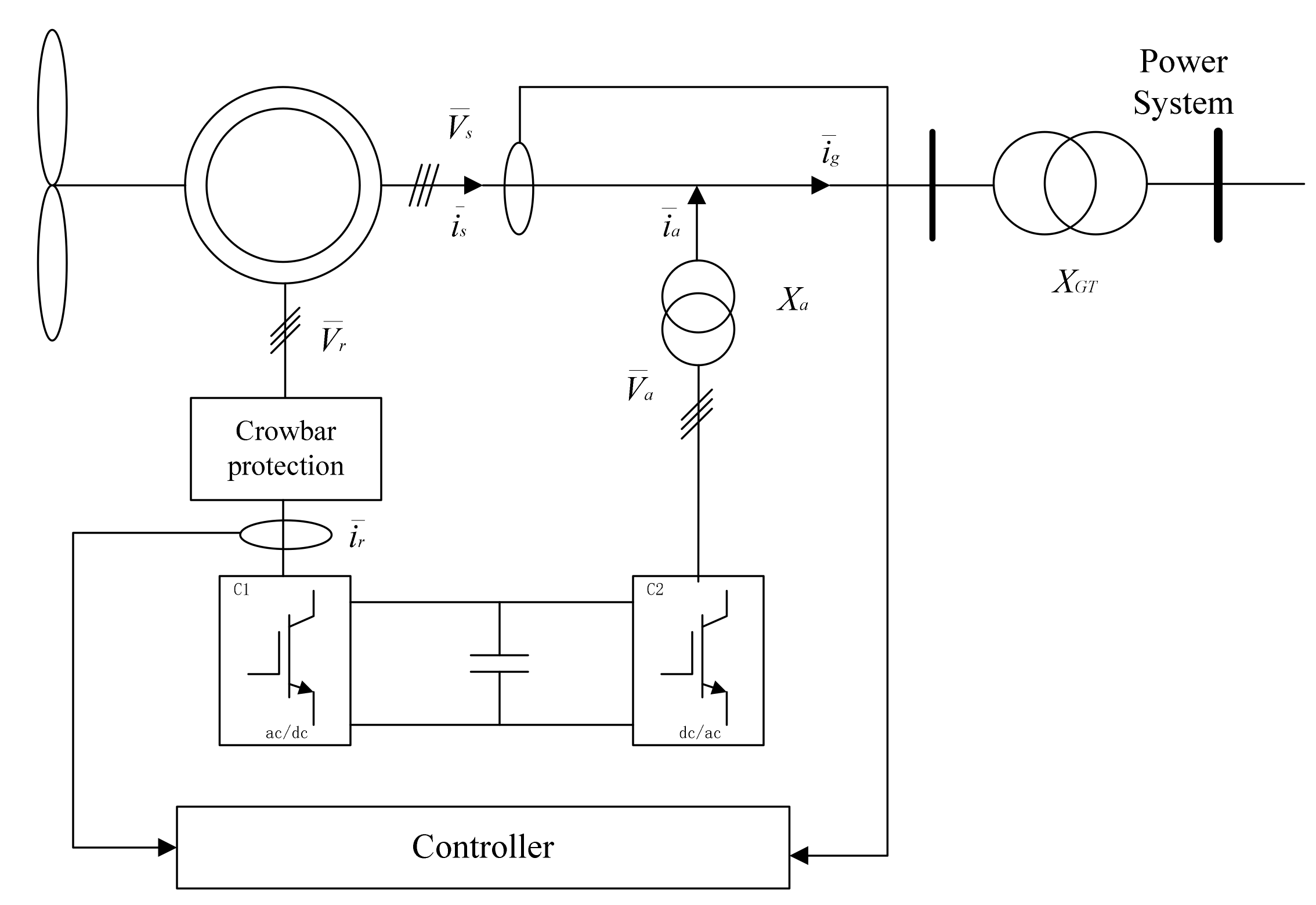
2.1. Single-Machine Hamiltonian Realization of Doubly Fed Wind Turbine

At present, the variable speed operation of wind turbines using doubly fed induction generators (DFIG) is emerging as the preferred technology. This is due mainly to the reduced mechanical loads on the wind turbines and the increased possibilities of control of both real and reactive power to allow easier integration of wind turbines into the power system [20].
A typical configuration of a DFIG based on a wind turbine is shown schematically in Figure 1 [21]:
First, the doubly fed wind turbine includes a transmission mechanism and doubly fed induction generator. Three-phase stator and rotor windings of an induction machine can be represented using two sets of orthogonal fictitious coils. A generalized fifth-order machine model is developed using appropriate coordinate transformation. The transmission mechanism can be expressed as a first-order model, and the doubly fed induction generator can be expressed as a second-order model, which ignores the electromagnetic transient of the stator. Therefore, the doubly fed wind turbine can be expressed as the third-order model via model order reduction [22]:
2 H tot d s d t = P s P m = E d i d s E q i q s P m , d E q d t = s ω s E d E q X s X s i ds T 0 + ω s L m L rr u d r , d E d d t = s ω s E q E d + X s X s i q s T 0 ω s L m L rr u q r .
Therefore, Equation (1) is a two-input and third-order model of the wind turbine in the d-q coordinate system, where s , E d , and E q are states, and u d r and u q r are inputs. The variables of the wind turbine model are shown in Appendix A.
The Hamiltonian energy function of the system is considered as
H = s 2 2 + 1 2 E q + P m 2 i q s 2 + 1 2 E d + P m 2 i d s 2 .
The System (1) is transformed into a PCH model: :
d d t [ s E q E d ] = [ 0 i q s 2 H t o t i d s 2 H t o t 0 1 T 0 s ω s 0 s ω s 1 T 0 ] H + [ 0 0 ω s L m L r r 0 0 ω s L m L r r ] [ u d r u q r ] + [ 0 i d s T 0 ( X s X s ) + P m 2 T 0 i q s + s ω s P m 2 i d s i q s T 0 ( X s X s ) + P m 2 T 0 i d s s ω s P m 2 i q s ] .
At the same time, the control law u = u d r u q r = K + μ is designed with pre-feedback K and output feedback μ , and the PCH-D form of the closed-loop System (1) is obtained [23].
d d t s E q E d = 0 i q s 2 H tot i d s 2 H tot i q s 2 H t o t 1 T 0 s ω s i d s 2 H tot s ω s 1 T 0 H + 0 0 ω s L m L rr 0 0 ω s L m L rr μ dr μ q r = Δ J R H + G μ ,
y = G T H = ω s L m L rr E q + P m 2 i q s ω s L m L rr E q + P m 2 i q s .

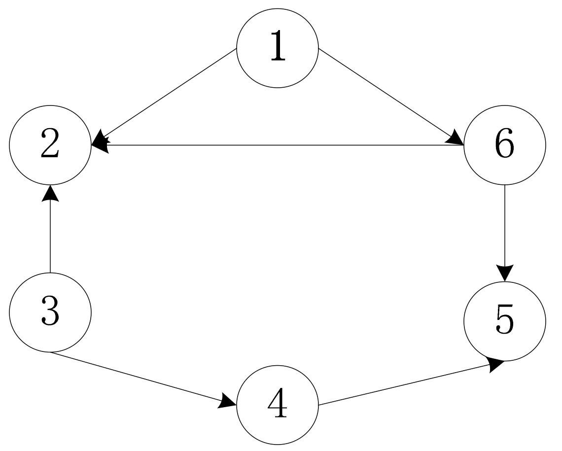
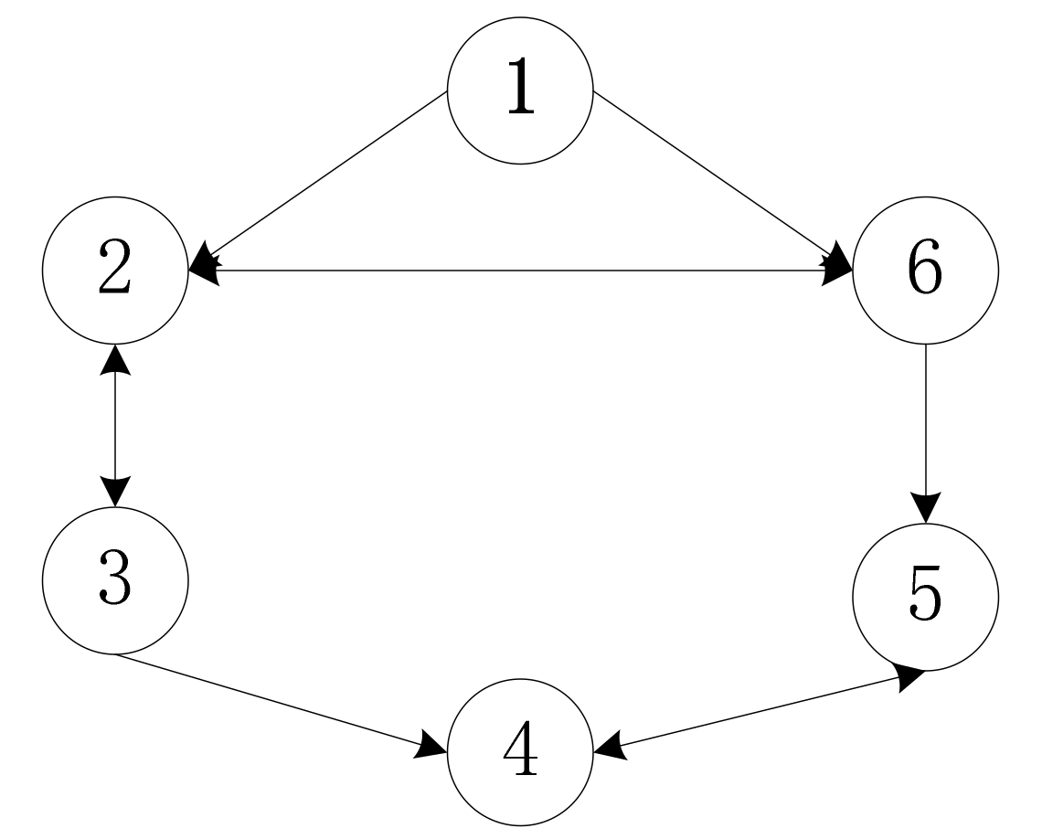
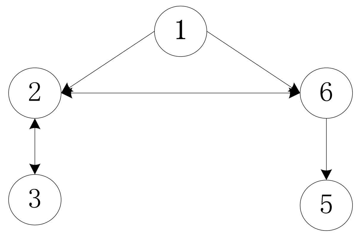
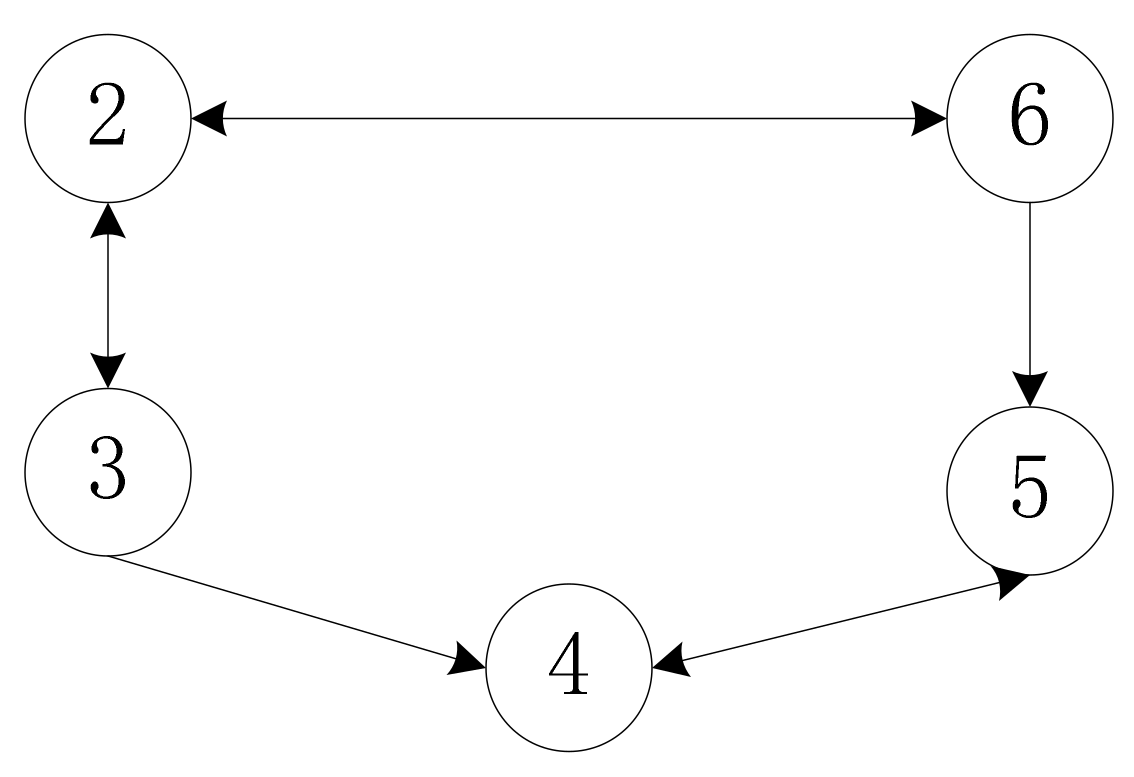
2.2. Conceptions of Graph Theory

With the rapid development of offshore wind farms, the installed capacity of the single unit is increased and the ability for communication control is increasing. Besides physical properties, it has communication properties and intelligent properties. Wind turbines in offshore wind farms are interconnected to form a network topology. The parameters and states of each unit are coordinated through the networked communication, and the distributed control strategy is designed to achieve consistent output of each unit in the system. In this section, we introduce some basic concepts in graph theory [24].
Considering that there are n nodes communicating with each other in the system, the communication topology graph is usually recorded G V , E d g e , where V = v 1 , v 2 , , v n are a set of nodes. E d g e V × V are a set of the edges representing the communication of information between two nodes. If the edge is directed, G V , E d g e is called a directed graph; otherwise, it is called an undirected graph. The edge ( v i , v j ) indicates that the node j can obtain information about the node i , and each graph has its own adjacency matrix A = {aij} ∈ Rn × n and Laplacian matrix L . If v j , v i E d g e , aij > 0; otherwise a i j = 0 . In the paper, if a i j 0 aij takes the value 1. In addition, an important definition is given below.
Definition 1 
[19]. Consider the topology graph G V , E d g e for the node i V , set:
  • N s i = j v j , v i E d g e , v i , v j E d g e represents the unidirectional neighbor node of the node i ;
  • N d i = j v j , v i E d g e , v i , v j E d g e represents the bidirectional neighbor node of the node i ;
  • N p i = j v i , v j E d g e , v j , v i E d g e represents the potential neighbor node of the node i .
Remark 1. 
For any two nodes i , j , if i N s j , j N p i .
Remark 2. 
For a weakly-connected graph G V , E d g e , if there is a path v i , v j in the graph, N s i N p i N d i is the directed graph after supplementing path v j , v i , where adjacent nodes communicate bidirectionally; it can be regarded as a special form of the undirected graph.

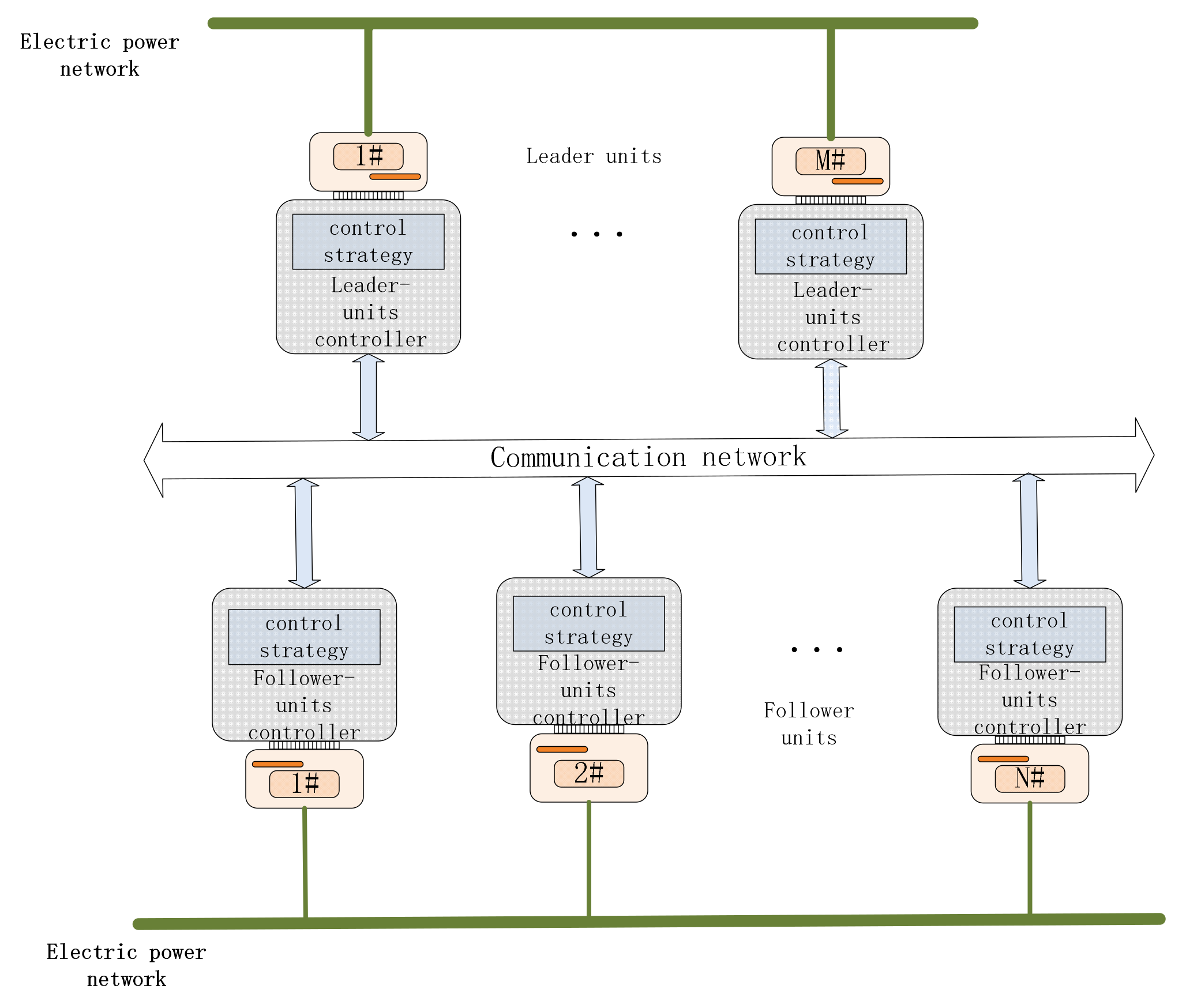
3. Leader-Follower Distributed Control Strategy

Because of the complexity and severity of the marine environment, the fault rate of offshore wind turbines is relatively high, and the control system, gearbox, or generator may cause the wind turbine to shut down [25,26]. Considering the information communication between the units in the entire wind farm, a single-machine fault will not only affect the stability of related wind turbines, but also decrease the efficiency of the operation of the entire wind farm. When a single-machine fault occurs in wind farm, the leader-follower control strategy needs to work such that the operation of other units will not be adversely affected. In this section, single-machine fault includes leader and follower faults. The distributed control strategies of leader and follower units are designed respectively.

3.1. Control Strategy of Leader

In the analysis above, the units in the wind farm are divided into leader and follower units, and the electrical control system is shown schematically in Figure 2. Considering the directionality of the communication, the network topology of the system is regarded as a directed graph.
Assumption 1. 
The network topology formed by offshore wind turbines is a directed graph with root nodes and there is at least one directed spanning tree.
In this paper, the root node in the directed graph is selected as the leader and the other nodes are used as followers. The PCH-D model of the single unit is applied to the wind turbine group through the previous Hamiltonian realization of the doubly fed wind turbine. The PCH-D model of the generator group of the leader is:
x ˙ l = J l R l H l + G l μ l , y l = G l T H l ,
where J l , R l , and G l are identical to J , R , and G in Equation (4), which are marked with the subscript l to indicate the parameters of the leader unit.
In the distributed system, it is assumed that the leader unit can directly obtain an output reference value y r of the stable operation state. Next, the energy shaping and damping injection method in the Hamiltonian energy theory is introduced to design the control strategy of the leader [16]. The current Hamiltonian function of the leader is H l x l . Setting the expected Hamiltonian function H r x l , the output of the leader y l can converge to the reference value y r , namely:
G l T H r = y l + d = y r ,
where the current output of the leader y l is adjusted by the value d .
The energy shaping control strategy μ ¯ l is substituted into the PCH-D model of the leader:
J l R l H l x l + G l μ ¯ l = J l R l H r x l .
Then:
G l μ ¯ l = J l R l H r x l J l R l H l x l ,
where Equation (9) needs to meet the matching conditions [13], therefore:
G s J l R l H r x l J l R l H l x l = 0 ,
where G s is a left zeroing factor with full rank satisfying G s G s = 0 .
Observing that G l is a matrix with full column rank, Equation (9) is simplified to obtain the energy shaping control strategy μ ¯ l as follows:
μ ¯ l = G l T G l 1 G l T J l R l H r x l H l x l .
Based on the above analysis, in order to make the output power of the leader reach the given reference value, the control strategy of the leader should be designed.
Theorem 1. 
Considering the leader unit in Equation (6) in the offshore wind farm, the control strategy of the leader is designed using the energy shaping and damping injection method:
μ l = μ ¯ l + μ r = μ ¯ d r l μ ¯ q r l + μ d r μ q r = L r r l 2 ω s l 2 L m l 2 d 1 T 0 l + s l ω s l d 2 s l ω s l d 1 d 2 T 0 l + μ d r μ q r ,
where μ r = μ d r μ q r is the control strategy to be redesigned such that the new Hamiltonian function H r x l obtained by the leader after adjustment can meet Equation (9), and the output of the leader unit eventually converges to the value y r .
Proof of Theorem 1. 
For the convenience, the adjustment value d is decomposed into d = G l T d ¯ , where d ¯ = L rr l ω s l L m l 0 d 1 d 2 T , we have:
y r = G l T H r x l = y l + d = G l T H l x l + G l T d ¯ .
Then:
H r x l = H l x l + d ¯ = s l E q l + P m l 2 i q s l + L rr l ω s l L m l d 1 E d l + P m l 2 i d s l L rr l ω s l L m l d 2 .
According to the above energy shaping control strategy μ ¯ l :
μ ¯ l = G l T G l 1 G l T J l R l H r x l H l x l = G l T G l 1 G l T J l R l d ¯ ,
we have:
μ ¯ l = μ ¯ d r l μ ¯ q r l = L rr l 2 ω s l 2 L m l 2 d 1 T 0 l + s l ω s l d 2 s l ω s l d 1 d 2 T 0 l .
Then, the control strategy of leader is obtained as:
μ l = μ ¯ l + μ r = μ ¯ d r l μ ¯ q r l + μ d r μ q r = L rr l 2 ω s l 2 L m l 2 d 1 T 0 l + s l ω s l d 2 s l ω s l d 1 d 2 T 0 l + μ d r μ q r .
Therefore, the energy shaping control strategy of the leader in Equation (12) is obtained, which can modify the Hamiltonian energy function to make the output of the leader reach the reference value y r . The proof is completed. □

3.2. Control Strategy of the Follower Unit

The follower units not only need to achieve output synchronization through the distributed control, but also make their outputs follow the leader’s output under the leader-follower control. Considering the PCH-D Equation (4) of the wind turbine, the PCH-D model of follower unit is:
x ˙ i = J i R i H i + G i μ i , y i = G i T H i .
Here, being marked with the subscript i indicates the parameters of the follower unit. When the system operates stably, the PCH-D model of the leader unit can be rewritten as:
x ˙ l = J l R l H l x l + G l μ r , y r = G l T H r x l ,
where y r = y l + d indicates the output of the leader unit after being adjusted by the value d . Now, the control strategy of the follower unit is designed to render it as following the leader. Then, the whole system can operate stably.
Theorem 2. 
Considering one wind farm cluster including leader units as in System (14) and follower units as in System (13), the network topology of the system is a directed connectivity graph with at least one directed spanning tree. Let μ r = 0 . The follower distributed control strategy μ i is taken as:
μ i = j = 1 N y i y j a i N + 1 y i y r , i , j = 1 , 2 , , N ,
where a i j = a i N + 1 = 1 . Under the control strategy, the output of the follower unit can follow the leader’s output to a consistent value and the whole closed-loop System (1) is globally stable.
Proof of Theorem 2. 
Consider the remaining N units as followers, then the leader model is:
x ˙ l = J l R l H r x l , y l = G l T H r x l .
The Hamiltonian energy function of the system is taken as:
H x = i = 1 N H i x i + H r x l .
Substituting the control strategy μ i into the PCH-D form given in System (13), we have:
x ˙ i = J i R i H i G i j = 1 N y i y j G i a i N + 1 y i y r .
Compute the derivative of the Hamiltonian function of the system:
H ˙ x = i = 1 N T H i x i x ˙ i + T H r x l x ˙ l = i = 1 N T H i x i J i R i H i G i j = 1 N y i y j G i a i N + 1 y i y r + T H r x l x ˙ l = i = 1 N + 1 T H i x i J i R i H i i = 1 N y i T i = 1 N + 1 a i j y i y j ,
where J T = J . It can be rewritten as:
H ˙ x = i = 1 N + 1 T H i x i R i H i i = 1 N y i T i = 1 N + 1 a i j y i y j .
Assuming that L N is a Laplacian matrix of the N units system, after joining the leader unit, L N + 1 is the Laplacian matrix of the whole N + 1 units system. L N + 1 is augmented by L N and we have a N + 1 j = 0 . Then, the above formula can be rewritten into a vector form as:
H ˙ = T H R H y ¯ T L N + 1 I 3 y ¯ ,
where, the output is y = y 1 , y 2 , , y N T , y _ _ = y 1 , y 2 , , y N , y r T is the output vector after augmentation, L N + 1 is N + 1 × N + 1 Laplacian matrix, and I 3 is 3 × 3 identity matrix.
Using the Hamiltonian energy function as the Lyapunov function V of the system, then:
V ˙ = H ˙ = T H R H y ¯ T L N + 1 I 3 y ¯ 0 .
It can be seen that the system can achieve global stability under the control strategy. Consider:
S = x | V ˙ = H ˙ = 0 = x | H T R H = 0 , L N + 1 I 3 y ¯ = 0 ,
where S S ˜ = L N + 1 I 3 y ¯ = 0 , and y 1 = y 2 = = y N = y r .
According to LaSalle’s invariant principle [27], when t , the solutions converge to the set S and the output y 1 = y 2 = = y N = y r is satisfied. Therefore, the output of the follower can follow the leader’s output, and the output of the cluster uniformly converges to the reference value y r . The proof is completed.  □
Remark 3. 
When the output of the wind turbine is consistent, it can be known that H T R H = 0 , and from the above equation, we have:
1 T 0 i E q i + P m i 2 i q s i 2 + 1 T 0 i E d i + P m i 2 i d s i 2 = 0 ,
where E q i + P m i 2 i q s i = 0 , P s i = E q i i q s i E d i i d s i = P m i , and the output of active power is equal to the input of mechanical power. When the system is globally stable, the output of active power for each wind turbine tends to be stable and consistent.

3.3. Analysis of the Control Strategy under Fault Conditions

First of all, it should be noted that the leader-follower control strategy designed in this paper replaces centralized control with distributed control, which can keep the normal operation of the wind turbine group in the no fault-condition. Moreover, in the case of unit fault, the adverse effects of the fault in the wind farm can be reduced. The specific analysis is as follows:
(1) Case 1: When the follower unit has a single-machine fault, assumption 1 holds; that is, the network topology formed by the remaining wind turbines is a directed graph, which contains at least one directed spanning tree. From the above analysis, the output of the leader unit adjusts through the adjustment value d ; the output of the follower unit will not affect the leader unit’s output. When the follower unit has a single-machine fault, under the leader-follower control strategy given in Equation (15), the fault-free follower unit follows the leader unit and each adjusts the other so that the entire system can achieve a consistent output in the case of a single-machine fault of the follower unit. At the same time, the active power output of the system reaches a stable value and the entire system operates stably.
(2) Case 2: When the leader unit has a single-machine fault, assumption 1 also has to hold. The network topology formed by the follower units contains at least one directed spanning tree in it. Under normal operating conditions, the follower unit control strategy acts as:
μ i = j = 1 N y i y j a i N + 1 y i y r , i , j = 1 , 2 , , N .
When the leader unit in System (14) fails, the faulty unit can no longer communicate with the original adjacent unit, thus, we have a i N + 1 = 0 , and the control of leader-follower strategy becomes a coordinated control strategy:
μ i = j = 1 N y i y j , i , j = 1 , 2 , , N .
Taking H x = i = 1 N H i x i as the Hamiltonian energy function of the system, it is known that the one-cluster systems are globally stable in the network topology formed by the remaining follower units in System (13), which contains a directed spanning tree; not only is the output of each unit consistent, but also the active power output is stable and consistent (refer to Reference [28] for details).
In summary, the units in the wind farm are divided into leader units and follower units based on the PCH-D model of the system. The leader-follower control strategy for a single-machine fault of the leader and follower unit is designed respectively. Under the single-machine fault of the follower unit, the faulty follower unit will not affect the leader unit, and the fault-free follower unit will still follow the leader unit and maintain normal working status through the control strategy. When the leader unit fails and there is a directed spanning tree structure between the fault-free units, the original leader-follower control strategy is equivalent to the cooperative control strategy, and the system can achieve stability via adjustment. Therefore, when the wind farm has a single-machine fault in the leader or follower unit, the fault-free units adjust mutually, and the system can operate stably under the single-machine fault; the active power output for each unit is also stable under the leader-follower control strategy. As a result, fault loss is minimized.

4. Leader-Follower Distributed Control Strategy under a Communication Fault Condition

In the previous section, the control strategy of the leader-follower is designed to make the wind turbine operate stably under a single-machine fault. When there is a communication fault in the wind turbine caused by error frames, unstable periods, and interference, there may be no directed spanning tree in the network topology, and the network topology graph becomes a weakly-connected graph. In this case, a new control strategy needs to be designed to ensure the stability of the system under a communication fault.
In this section, we select a directed communication path in the whole network topology with the root node as the leader unit and the remaining units as follower units. Considering that the output of the leader unit is modified by adjusting the value d , the follower unit follows the leader. Therefore, only the follower’s control strategy needs to be designed such that the follower unit can still follow the leader unit, and their output can achieve synchronization.
Theorem 3. 
Consider one wind farm cluster consisting of N + 1 wind turbines, which includes the leader and follower unit. The network topology of the system is a weakly-connected graph. Let μ r = 0 , and the follower control strategy μ i is designed as:
μ i = j N s i y i 2 y j j N d i y i y j K i y i a i N + 1 y i y r , i , j = 1 , 2 , , N ,
where a i j = a i N + 1 = 1 . Under the control strategy, the output of the follower unit can follow the leader’s output to a consistent value y r and the whole closed-loop system is globally stable.
Proof of Theorem 3. 
Select the root node on a directed communication path as leader unit and the remaining N units as follower units. The PCH-D model of leader unit is:
x ˙ l = J l R l H r x l , y l = G l T H r x l .
Take the Hamiltonian energy function of the system as:
H x = i = 1 N H i x i + H r x l .
Substituting the control strategy μ i into the PCH-D model of the follower unit, we have:
x ˙ i = J i R i H i G i j N s i y i 2 y j G i j N d i y i y j G i K i y i G i a i N + 1 y i y r ,
which can be rewritten as:
x ˙ i = ( J i R i ) H i + j N p i G i ( y i y j ) j N p i G i ( y i y j ) G i j N s i ( y i 2 y j ) G i j N d i ( y i y j ) G i K i y i G i a i ( N + 1 ) ( y i y r ) = ( J i R i ) H i + K i G i G i T H i j N p i G i G i T H j j N p i G i ( y i y j ) + G i j N s i y j G i j N s i ( y i y j ) G i j N d i ( y i y j ) G i K i G i T H i G i a i ( N + 1 ) ( y i y r ) = ( J i R i ) H i j N p i G i G i T H j + j N s i G i G i T H j G i j N s i N p i N d i ( y i y j ) G i a i ( N + 1 ) ( y i y r ) .
Take:
x ˜ ˙ i = J i R i H i j N p i G i G i T H j + j N s i G i G i T H j .
and x ˜ ˙ i is written as a vector form:
x ˜ ˙ = J ˜ R H ,
where
J ˜ = J 1 δ 12 G 1 G 2 T δ 1 N G 1 G N T δ 21 G 2 G 1 T J 2 δ 2 N G 2 G N T δ N 1 G N G 1 T δ N 2 G N G 1 T J N ,   R x = d i a g R 1 , R 2 , , R N ,   δ i j = 1 , j N p i 1 , j N s i 0 , other
,
From Remark 2, if i N s j , then j N p i , δ i j = δ j i , J ˜ T = J ˜ , and we have:
x ˙ i = x ˜ ˙ i G i j N s i N p i N d i y i y j G i a i N + 1 y i y r .
Rewrite G i j N s i N p i N d i y i y j into the vector form as G L ˜ N I 3 y , where y = y 1 , y 2 , , y N T . The Laplacian L ˜ N of the undirected connected graph shown here is different from the Laplacian matrix discussed in the previous section. It is the network topology without the leader unit, and the Laplacian matrix after the communication between the units becoming bidirectional, yet it is still a symmetric matrix and can be decomposed into L ˜ N = C ˜ C ˜ T , where C ˜ is a corresponding associative matrix.
Taking the derivative of the Hamiltonian function, we have:
H ˙ ( x ) = i = 1 N T H i ( x i ) x ˜ ˙ i i = 1 N T H i ( x i ) G i j N s i N p i N d i ( y i y j ) i = 1 N T H i ( x i ) G i a i ( N + 1 ) ( y i y r ) + T H r ( x l ) x ˙ l = i = 1 N T H i ( x i ) ( J ˜ i R i ) H i + T H r ( x l ) ( J l R l ) H r ( x l ) i = 1 N T H i ( x i ) G i j N s i N p i N d i ( y i y j ) i = 1 N T H i ( x i ) G i a i ( N + 1 ) ( y i y r ) ,
which can be rewritten as:
H ˙ x = i = 1 N + 1 T H i x i J ˜ i R i H i i = 1 N y i T j N s i N p i N d i y i y j i = 1 N y i T a i N + 1 y i y r = i = 1 N + 1 T H i x i J ˜ i R i H i i = 1 N y i T i = 1 N + 1 a i j y i y j ,
where J ˜ T = J ˜ . Therefore:
H ˙ x = i = 1 N + 1 T H i x i R i H i i = 1 N y i T i = 1 N + 1 a i j y i y j .
It is known that L ˜ N + 1 is the N + 1 Laplacian matrix after joining the leader unit into the N undirected topology, which is augmented by L ˜ N . Similarly, the above formula can be rewritten into a vector form as:
H ˙ = T H R H y ¯ T L ˜ N + 1 I 3 y ¯ ,
where the output is y = y 1 , y 2 , , y N T , y _ _ is the augmentation of y , L ˜ N + 1 is the N + 1 × N + 1 Laplacian matrix, and I 3 is 3 × 3 identity matrix.
Using the Hamiltonian energy function as the Lyapunov function V of the system, we have:
V ˙ = H ˙ = T H R H y ¯ T L ˜ N + 1 I 3 y ¯ = T H R H C ˜ I 3 T y ¯ 2 0 .
It can be seen that the system can achieve global stability under the control strategy. Similar to the proof in Theorem 2, when the system operates stably, the output y 1 = y 2 = = y N = y r is satisfied. The output of the follower unit is synchronous with the leader unit’s output and all the output uniformly converges to the reference value y r . The proof is completed. □

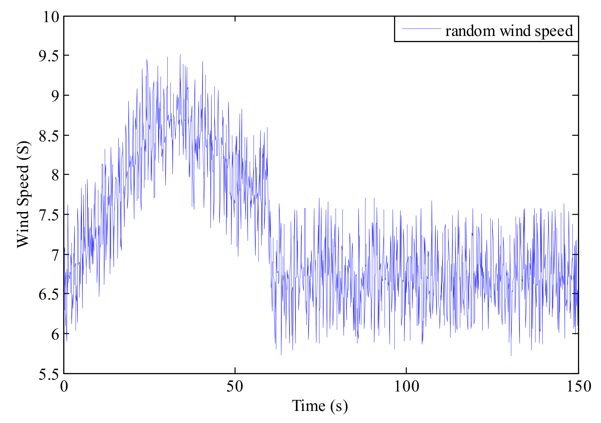
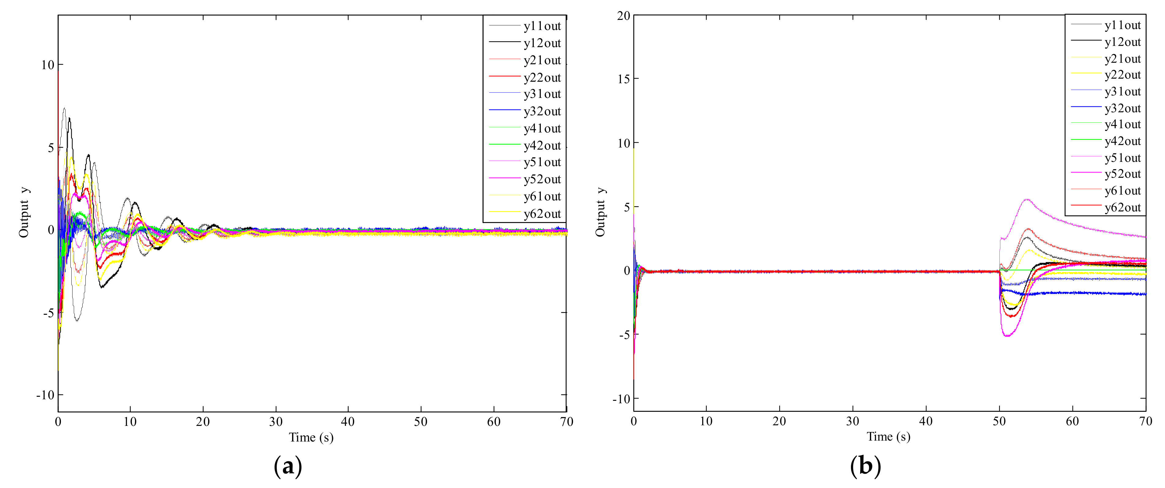
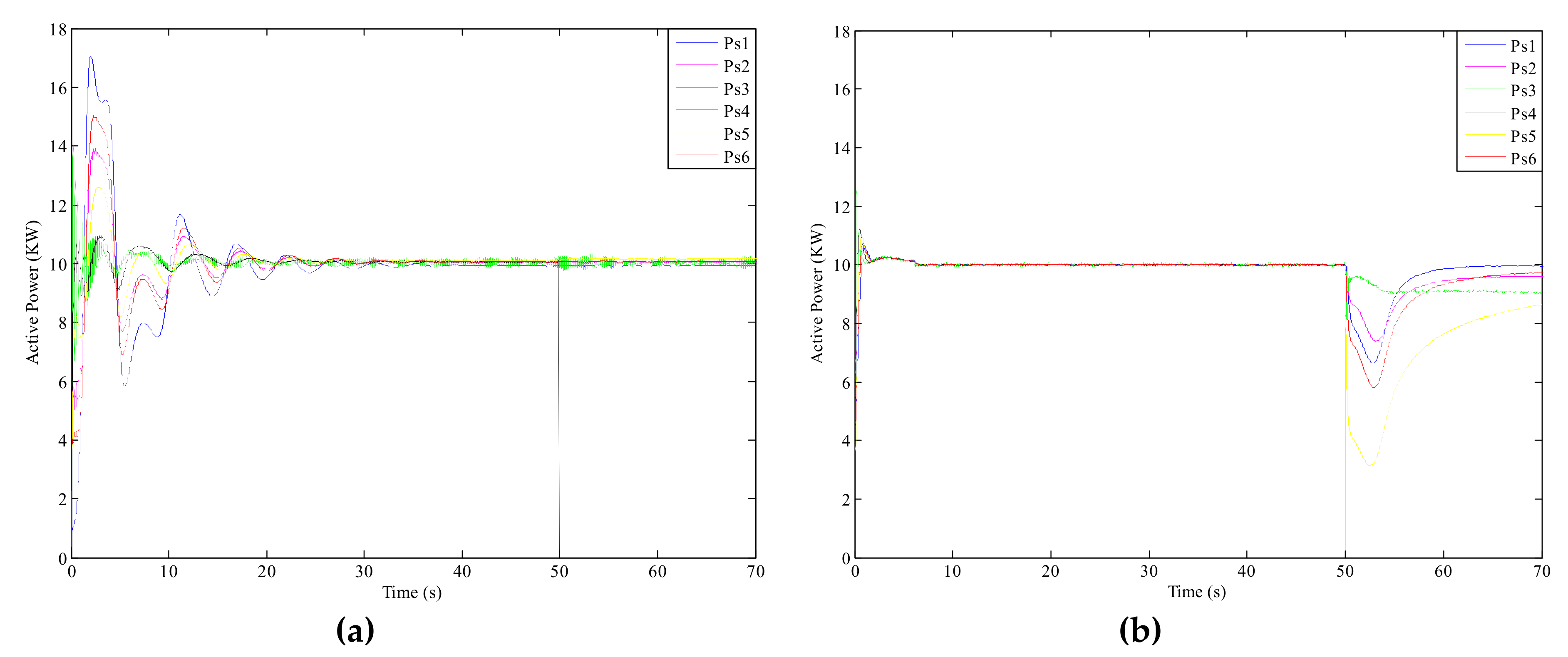
5. Simulation Verification

In this paper, simulations were carried out with the MATLAB R2014a software developed by MathWorks in American. It includes three parts: in the first part, although the follower unit fails due to the single-machine fault, the active power output can remains consistent through the leader-follower control strategy; in the second part, the leader unit fails due to the single-machine failure; however, the system operates stably because the leader-follower control strategy is introduced; in the third part, the leader-follower control strategy is effective when the system has communication fault resulting in a weak connection of the whole network communication. Here, six units were selected to form a wind-turbine group. The network topology of the system was a directed connected graph. It was assumed that the parameters of the wind turbine are the same. The main parameters are H tot = 4 s ; L s = 0.17 pu ; L r = 0.15 pu ; L m = 3.0 pu ; R s = 0.06 pu ; ω s = 3.14 pu ; i d s = 1.8 pu ; i q s = 1.6 pu ; and L rr = L m + L r , L ss = L m + L s [22].
The topology composed of the six wind turbines was a connected graph containing a directed spanning tree, as shown in Figure 3.

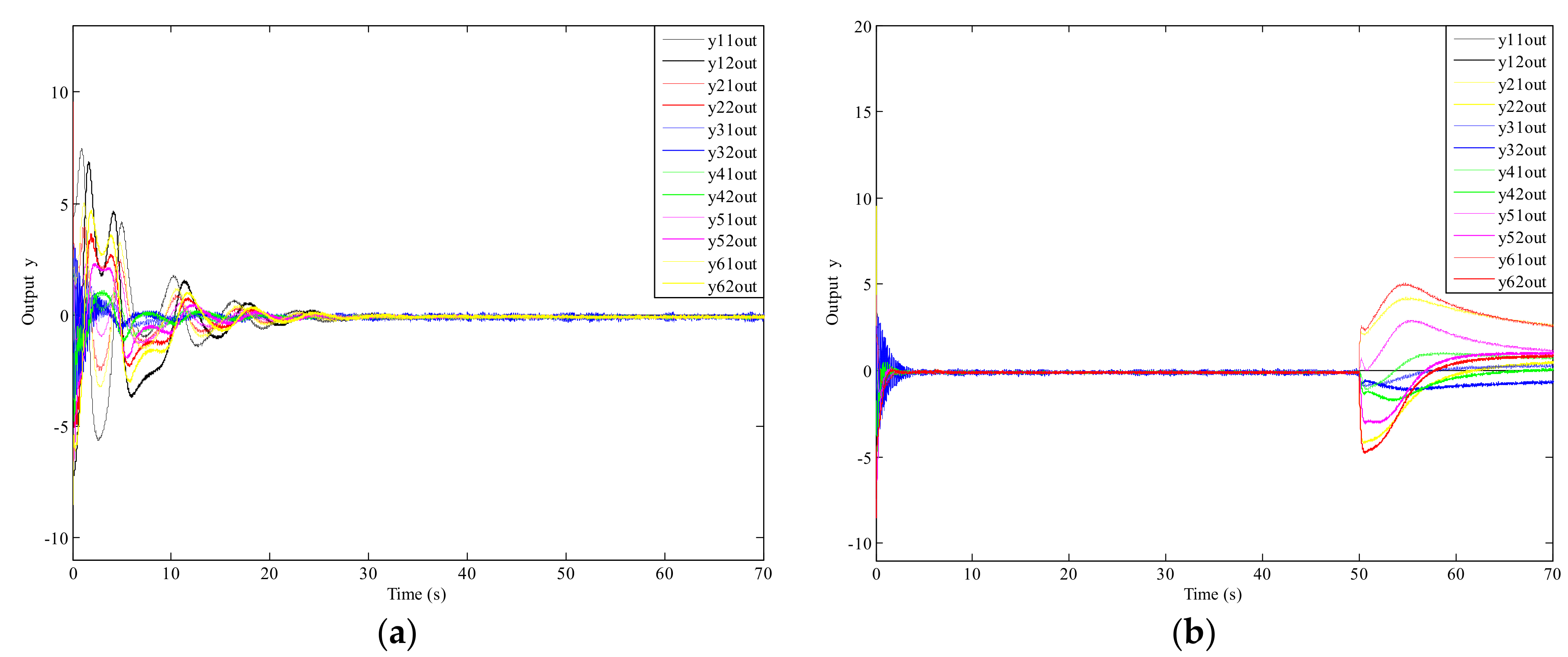
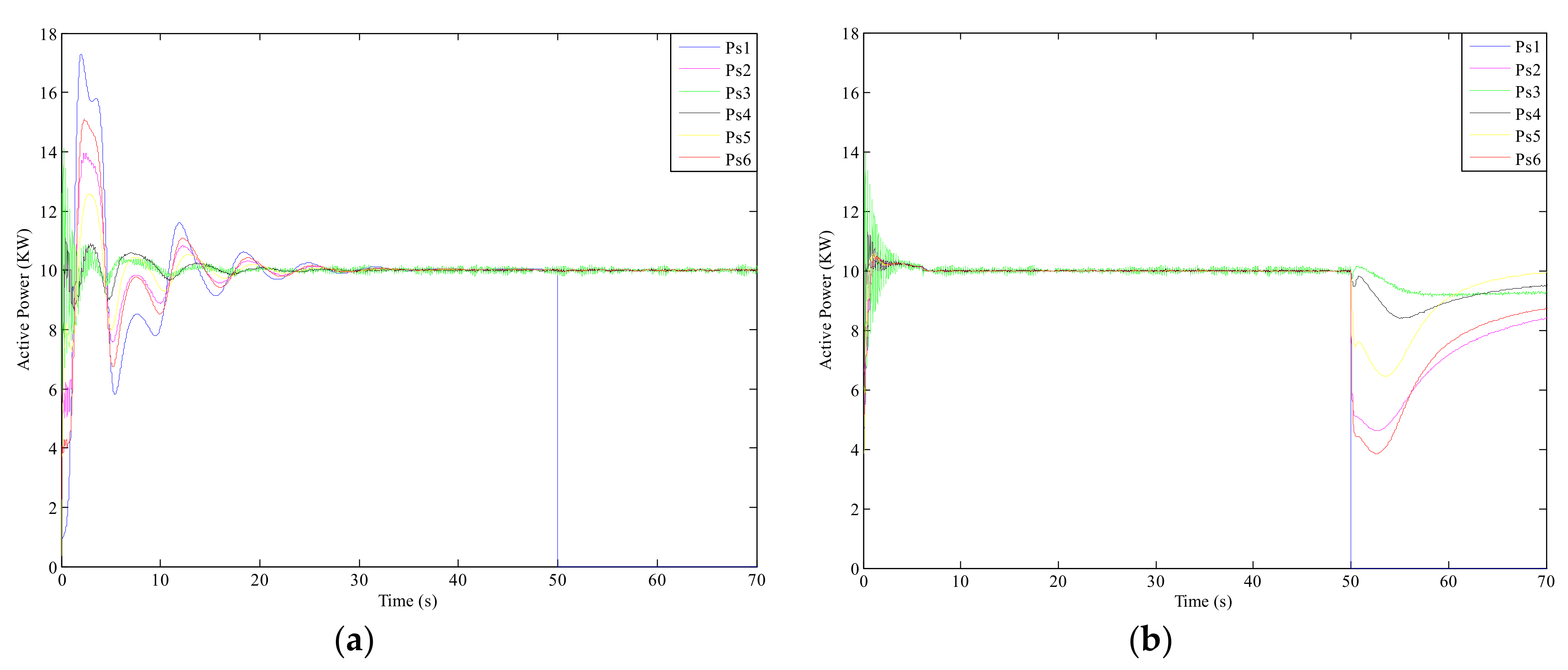
5.1. The Leader-Follower Control Strategy under Follower Unit Fault

For the topology of the six wind turbines, the initial output values of the six wind turbines were set, and the root node, No. 1, was selected as the leader unit. Then, 2, 3, 4, 5, and 6 were set as the follower units, and the adjustment value, d = d 1 d 2 , where d 1 = 0.7 , and d 2 = 1.3 , which were constant, were set. The distributed control strategy ( μ i ) derived from the previous reasoning was applied to the network, and the distributed control strategies of the six generators were:
μ 1 = μ ¯ l , μ 2 = y 1 + y 3 + y 6 3 y 2 , μ 3 = y 2 y 3 , μ 4 = y 5 + y 3 2 y 4 , μ 5 = y 6 + y 4 2 y 5 , μ 6 = y 1 + y 2 2 y 6 .
When t = 50 s, No. 4, one of the follower units, had a single-machine fault, and the topology graph of the generators was shown in Figure 4:
The distributed control strategy adopted by the fault-free unit was:
μ 1 = μ ¯ l , μ 2 = y 1 + y 3 + y 6 3 y 2 , μ 3 = y 2 y 3 , μ 5 = y 6 y 5 , μ 6 = y 1 + y 2 2 y 6 .
Due to the unpredictability of wind speed, a random wind speed variation was applied to investigate the control performance of the proposed approach, as shown in Figure 5.
The simulation results of the output response of each wind turbine under a leader-follower control strategy in the wind farm are shown in Figure 6a. The simulation results of the active power output under a leader-follower control strategy are shown in Figure 7a. The simulation results of output response under a cooperative control strategy are shown in Figure 6b, and the simulation results of the active power output under a cooperative control strategy are shown in Figure 7b. It can be seen in Figure 6a and Figure 7a that the output curves and the active power output fluctuated less at 20 s. After 30 s, the output converged to 0, and the active power output was equal to the input of mechanical power; the active power output of each unit converged to 10 kW, and the system operated stably. When the follower unit No. 4 shut down at t = 50 s, the output of active power for unit No. 4 dropped directly to 0, and the active power output for the other units did not fluctuate excessively. It also can be seen in Figure 6b and Figure 7b that the output of the other five units fluctuated greatly, and the system stability was affected by unit No.4. It can be seen that the single-fault unit affected other units and the whole system, and the leader-follower control strategy could effectively control the fault-free units from the influence of the fault unit and reduce the losses under the single-machine fault of a follower unit.

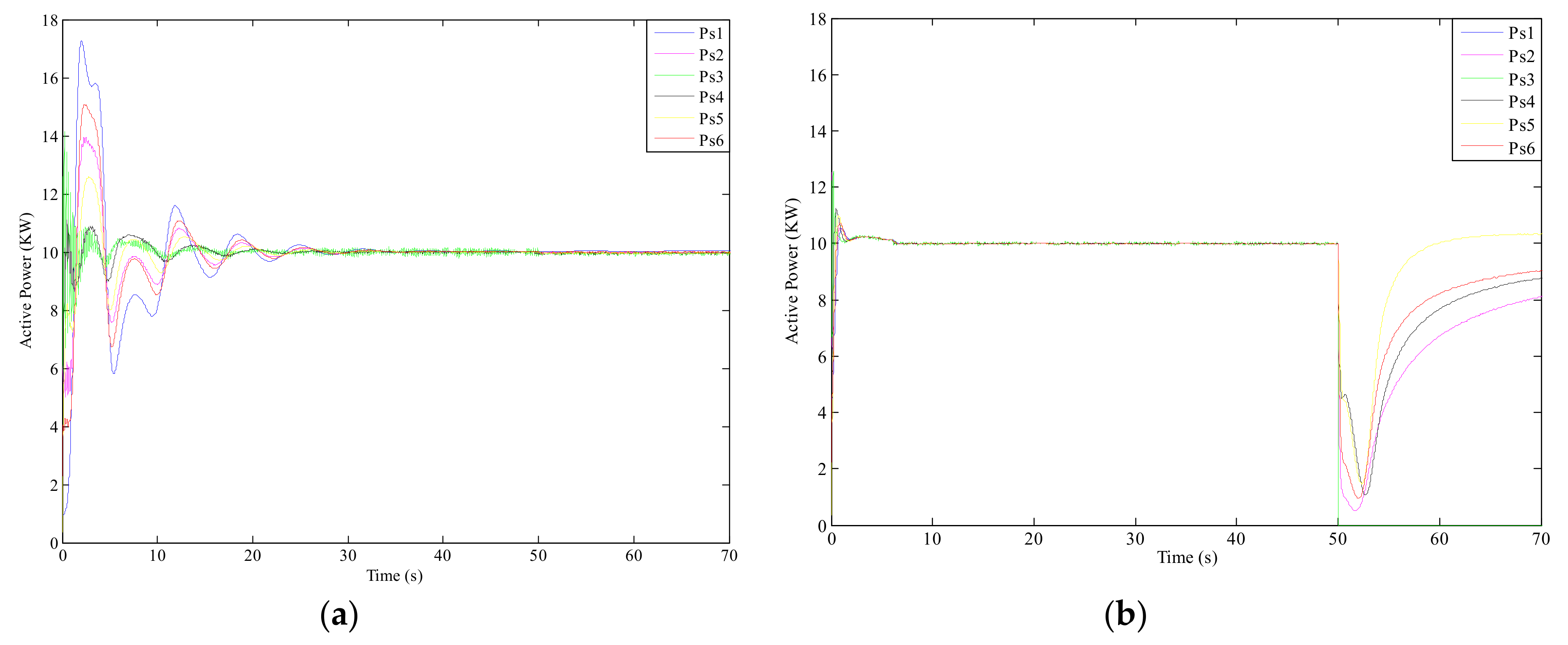
5.2. The Leader-Follower Control Strategy under a Leader Unit Fault

At t = 50 s, the leader unit, No. 1, had a single-machine fault. The topology graph of the generators was shown in Figure 8:
It contained a directed spanning tree, and the distributed control strategies adopted by the other fault-free units was:
μ 2 = y 3 + y 6 2 y 2 , μ 3 = y 2 y 3 , μ 4 = y 5 + y 3 2 y 4 , μ 5 = y 6 + y 4 2 y 5 , μ 6 = y 2 y 6 .
The simulation results of the output response of each wind turbine under a leader-follower control strategy in the wind farm are shown in Figure 9a. The simulation results of the active power output under a leader-follower control strategy are shown in Figure 10a. Furthermore, the simulation results of the output response under a cooperative control strategy are shown in Figure 9b. The simulation results of the active power output under a cooperative control strategy are shown in Figure 10b.
It can be seen from Figure 9a and Figure 10a that the adjustment time of the system was about 30 s, the output of the system was stable, and the fluctuation reduced after 20 s. When the leader unit No. 1 had a single-machine fault, the active power of the unit was 0. The system still contained the directed spanning tree, and the remaining units could adjust mutually under the leader-follower control strategy. Therefore, the system operated stably and the output of active power was stable. The leader-follower control strategy could also be applied in the case of a single-machine fault of the leader unit. Furthermore, it can be seen from Figure 9b and Figure 10b that the output of fault-free units had a larger fluctuation after the unit No. 1 shutting down, while the active power output of the five fault-free units had a larger decline under the influence of the unit No. 1. The leader-follower control strategy could make fault-free units adjust to ensure the stability of the system, which further illustrates that the leader-follower control strategy has stronger fault tolerance under a failure situation.

5.3. The Leader-Follower Control Strategy under a Communication Failure

Based on the aforementioned parameters of the six wind turbines and network topology graph, when t = 50 s, a communication fault occurred in unit No. 2 and unit No. 5. Thus, the information for the parameters and feedback on the status of the system cannot be relayed. As a result, the network topology became a weakly-connected graph, as shown in Figure 11.
The network topology contained a path: 1-6-5. The root node of the path was selected as the leader unit, and the units 2, 3, 4, 5, and 6, were all used as follower units. For the communication fault, the leader-follower control strategy μ i was introduced. In the topology graph of the wind-turbine group, we had:
N s 2 = 3 , 6 , N d 2 = 0 , N p 2 = 0 ; N s 3 = 0 , N d 3 = 0 , N p 3 = 2 , 4 ; N s 4 = 3 , N d 4 = 0 , N p 4 = 5 ; N s 5 = 4 , 6 , N d 5 = 0 , N p 5 = 0 ; N s 6 = 0 , N d 6 = 0 , N p 6 = 2 , 5 .
The control strategies for the six wind turbines were designed as:
μ 1 = μ ¯ l , μ 2 = y 1 + 2 y 3 + 2 y 6 3 y 2 , μ 3 = 2 y 3 , μ 4 = 2 y 3 2 y 4 , μ 5 = 2 y 6 + 2 y 4 2 y 5 , μ 6 = y 1 3 y 6 .
The simulation results of the output response under a leader-follower control strategy are shown in Figure 12a, while those of the active power output under a leader-follower control strategy are shown in Figure 13a. Furthermore, the simulation results of the output response under a cooperative control strategy are shown in Figure 12b, while the active power output under a cooperative control strategy is shown in Figure 13b.
It can be seen from Figure 12a and Figure 13a that the output curves of the leader and follower units could converge after 30 s such that the system could achieve stable operation and output. The output of active power fluctuated less after 10 s, and tended to be stable after 30 s. When the network topology failed at 50 s, there was no directed spanning tree in the entire network topology, and the network topology became a weakly-connected graph, where the units No.1 and No.3 could not get the information from the other units, and the original control strategy was out of control. It can be seen from Figure 12b and Figure 13b that the active power of the unit No.1 and No.3 was reduced to 0 kW, and the output and active power of other units had a large fluctuation under the influence of the faulty unit. Compared with Figure 12 and Figure 13, the system could maintain stable operation after the adjustment time, and the active power output tended to be stable through the leader-follower control strategy.
Through the above simulation, implementation, and analysis, it was apparent that when the leader-follower distributed control strategy was adopted, the wind turbine maintained stable operation under the condition of a single-machine and communication network failure; as a result, the stability and reliability of the wind farm in the complex and harsh marine environment was improved. At the same time, the economic losses caused by the fault were reduced; thus, the requirements of the control strategy were met.

6. Conclusions

In view of offshore doubly fed wind farms, the leader-follower distributed control method was introduced in the case of single-machine and communication fault conditions. On the basis of Hamilton energy theory, the corresponding control strategies were proposed in different fault situations that enable the wind turbine to achieve stability after adjustment and minimizes the loss caused by fault(s). The main innovations of this paper are as follows: (1) By applying distributed control to the network structure of wind turbines and combining with the Hamilton model of wind turbines, the distributed control of wind turbines was achieved. Compared with traditional centralized control methods, this control system was more flexible and reliable. (2) Analyzing the system under the single-machine fault, and designing the leader-follower control strategy to achieve global stability of the system under the single-machine fault of the leader and follower units by means of Hamiltonian energy shaping and damping injection method. (3) Designing the leader-follower control strategy for the weakly-connected graph under the communication fault of the system such that the system could operate stably under the communication fault. Furthermore, the output of active power was stable, which improved the stability and reliability of the system. This design method provided new ideas for the development and application of wind farms in the future.

Author Contributions

B.W. contributed to the design, analysis, and writing of the paper. Z.T. analyzed the data and performed the computer simulations. X.G., W.L. and X.C. contributed to give some suggestions and consultation.

Funding

This research was funded by National Natural Science Foundation of China (NSFC) under grant number 51777058.

Conflicts of Interest

The authors declare no conflict of interest.

Appendix A. List of Symbols

i s , i r , i g stator, rotor, and generated current
V s , V r stator and rotor voltage
V a , i a stator side converter voltage and current
X G T , X a transformer reactance
R r rotor resistance
ω s synchronous angle speed
L m mutual inductance
L ss , L rr stator and rotor inductance
s rotor slip rate
i d s , i q s dq-axis stator current
X s , X s stator transient or short circuit reactance and open circuit reactance
E d , E q dq-axis transient reactance voltages
u d r , u q r dq-axis rotor voltage
H t o t inertia constant
P m mechanical power
P s stator active power
Q s stator reactive power

References

  1. Van Hertem, D.; Gomis-Bellmunt, O.; Liang, J. HVDC Grids: For Offshore and Supergrid of the Future; Wiley-IEEE Press: Hoboken, NJ, USA, 2016. [Google Scholar]
  2. Wu, Q.W.; Sun, Y.Z. Modeling and Modern Control of Wind Power; Wiley-IEEE Press: Hoboken, NJ, USA, 2018. [Google Scholar]
  3. Sakamuri, J.N.; Rather, Z.H.; Rimez, J.; Altin, M.; Goksu, O.; Cutululis, N.A. Coordinated voltage control in offshore HVDC connected cluster of wind power plants. IEEE Trans. Sustain. Energy 2016, 7, 1592–1601. [Google Scholar] [CrossRef]
  4. Lu, T.G.; Wang, Z.Y.; Ai, Q.; Lee, W.J. Interactive model for energy management of clustered microgrids. IEEE Trans. Ind. Appl. 2017, 53, 1739–1750. [Google Scholar] [CrossRef]
  5. Ackermann, T. Wind Power in Power Systems; John Wiley & Sons: Chichester, UK, 2005. [Google Scholar]
  6. Xu, Y.L.; Zhang, W.; Liu, W.X.; Wang, X.; Ferrese, F.; Zang, C.Z.; Yu, H.B. Distributed subgradient- based coordination of multiple renewable generators in a microgrid. IEEE Trans. Power Syst. 2014, 29, 23–32. [Google Scholar] [CrossRef]
  7. Gao, X.D.; Meng, K.; Dong, Z.Y.; Wang, D.X.; EI Moursi, M.S.; Wong, K.P. Cooperation-driven distributed control scheme for large-scale wind farm active power regulation. IEEE Trans. Energy Convers. 2017, 32, 1240–1250. [Google Scholar] [CrossRef]
  8. Yang, S.P.; Tan, S.C.; Xu, J.X. Consensus based approach for economic dispatch problem in a smart grid. IEEE Trans. Power Syst. 2013, 28, 4416–4426. [Google Scholar] [CrossRef]
  9. Zhang, Z.; Chow, M.Y. Convergence analysis of the incremental cost consensus algorithm under different communication network topologies in a smart grid. IEEE Trans. Power Syst. 2012, 27, 1761–1768. [Google Scholar] [CrossRef]
  10. Zhang, X.J.; Karady, G.G.; Ariaratnam, S.T. Optimal Allocation of CHP-Based Distributed Generation on Urban Energy Distribution Networks. IEEE Trans. Sustain. Energy 2014, 5, 246–253. [Google Scholar] [CrossRef]
  11. Ajorlou, A.; Aghdam, A.G. Connectivity Preservation in Nonholonomic Multi-Agent Systems: A Bounded Distributed Control Strategy. IEEE Trans. Autom. Control 2013, 58, 2366–2371. [Google Scholar] [CrossRef]
  12. Zhao, C.C.; He, J.P.; Cheng, P.; Chen, J.M. Consensus-based energy management in smart grid with transmission losses and directed communication. IEEE Trans. Smart Grid 2017, 8, 2049–2061. [Google Scholar] [CrossRef]
  13. Wang, Z.X.; Jiang, C.W.; Ai, Q.; Wang, C.M. The key technology of offshore wind farm and its new development in China. Renew. Sustain. Energy Rev. 2009, 13, 216–222. [Google Scholar]
  14. Kheshti, M.; Kang, X.N.; Song, G.B.; Jiao, Z.B. Modeling and Fault Analysis of Doubly Fed Induction Generators for Gansu Wind Farm Application. Can. J. Electr. Comput. Eng. 2015, 38, 52–64. [Google Scholar] [CrossRef]
  15. Jia, K.; Chen, R.; Xuan, Z.W.; Yang, Z.; Fang, Y.; Bi, T.S. Fault characteristics and protection adaptability analysis in VSC-HVDC-connected offshore wind farm integration system. IET Renew. Power Gener. 2018, 12, 1547–1554. [Google Scholar] [CrossRef]
  16. Ren, W.; Beard, R.W. Distributed Consensus in Multi-Vehicle Cooperation Control; Springer-Verlag: London, UK, 2008. [Google Scholar]
  17. Ortega, R.; van der Schaft, A.J.; Maschke, B.; Escobar, G. Interconnection and damping assignment passivity-based control of port-controlled Hamiltonian systems. Automatica 2002, 38, 585–596. [Google Scholar] [CrossRef]
  18. Wang, Y.Z. Generalized Controlled Hamiltonian System: Realization, Control and Applications; Science Press: Beijing, China, 2007. [Google Scholar]
  19. Li, C.S.; Wang, Y.Z. Protocol design for output consensus of port-controlled Hamiltonian multi-agent systems. Acta Autom. Sin. 2014, 40, 415–422. [Google Scholar] [CrossRef]
  20. Muller, S.; Deicke, M.; De Doncker, R.W. Doubly fed induction generator systems for wind turbines. IEEE Ind. Appl. Mag. 2002, 8, 26–33. [Google Scholar] [CrossRef]
  21. Ekanayake, J.B.; Holdsworth, L.; Jenkins, N. Comparison of 5th order and 3rd order machine models for doubly fed induction generator (DFIG) wind turbines. Electr. Power Syst. Res. 2003, 67, 207–215. [Google Scholar] [CrossRef]
  22. Wu, F.; Zhang, X.P.; Ju, P.; Sterling, M.J.H. Decentralized nonlinear control of wind turbine with doubly fed induction generator. IEEE Trans. Power Syst. 2008, 23, 613–621. [Google Scholar]
  23. Wang, B.; Tian, M.; Lin, T.J.; Hu, Y.L. Distributed complementary control research of wind turbines in two offshore wind farms. Sustainability 2018, 10, 553. [Google Scholar] [CrossRef]
  24. Mesbahi, M.; Egerstedt, M. Graph Theoretic Methods in Multiagent Networks; Princeton University Press: Princeton, NJ, USA, 2010. [Google Scholar]
  25. Badihi, H.; Zhang, Y.M.; Hong, H. Wind Turbine Fault Diagnosis and Fault-Tolerant Torque Load Control Against Actuator Faults. IEEE Trans. Control Syst. Technol. 2015, 23, 1351–1372. [Google Scholar] [CrossRef]
  26. Blesa, J.; Jiménez, P.; Rotondo, D.; Nejjari, F.; Puig, V. An Interval NLPV Parity Equations Approach for Fault Detection and Isolation of a Wind Farm. IEEE Trans. Ind. Electron. 2015, 62, 3794–3805. [Google Scholar] [CrossRef]
  27. Khalil, H.K. Nonlinear Systems, 3rd ed.; Prentice Hall: Upper Saddle River, NJ, USA, 2002. [Google Scholar]
  28. Wang, B.; Wu, Q.X.; Tian, M.; Hu, Q.Y. Distributed coordinated control of offshore doubly fed wind turbine groups based on the Hamiltonian energy method. Sustainability 2017, 9, 1448. [Google Scholar] [CrossRef]
Figure 1. Basic configuration of a DFIG wind turbine.
Sustainability 11 02290 g001
Figure 2. Offshore wind farm group distributed control system.
Sustainability 11 02290 g002
Figure 3. Network topology of a simulated offshore wind farm.
Sustainability 11 02290 g003
Figure 4. Follower unit fault.
Sustainability 11 02290 g004
Figure 5. The curve of random wind speed.
Sustainability 11 02290 g005
Figure 6. (a) Turbine group response under a leader-follower control strategy. (b) Wind turbine group response under a cooperative control strategy.
Sustainability 11 02290 g006
Figure 7. (a) Turbine active power output under a leader-follower control strategy; (b) Wind turbine active power output under a cooperative control strategy.
Sustainability 11 02290 g007
Figure 8. Leader unit fault.
Sustainability 11 02290 g008
Figure 9. (a) Turbine group response under a leader-follower control strategy. (b) Wind turbine group response under a cooperative control strategy.
Sustainability 11 02290 g009
Figure 10. (a) Wind turbine active power output under a leader-follower control strategy. (b) Wind turbine active power output under a cooperative control strategy.
Sustainability 11 02290 g010
Figure 11. Wind turbine communication fault.
Sustainability 11 02290 g011
Figure 12. (a) Wind turbine group response under a leader-follower control strategy. (b) Wind turbine group response under a cooperative control strategy.
Sustainability 11 02290 g012
Figure 13. (a) Wind turbine active power output under a leader-follower control strategy. (b) Wind turbine active power output under a cooperative control strategy.
Sustainability 11 02290 g013

