Abstract
The increasing daily rate of environmental pollution, due to electrical power generation from fossil fuel sources in different societies, urges the researchers to study alternative solutions. These solutions can be summarized into either finding other clean, renewable sources or managing the available sources optimally. This research represents smart electrical interconnection management between some of the Egyptian seaports for optimal operation, with a clean sustainable environment as the target. The optimum ports’ commitment operation works through certain technical constraints to attain optimal economic and environmental factors. One of the main objectives of this study is the reduction of carbon dioxide (CO2) emission, which is released from the electrical power generation that covers the seaports demands. It is progressed through the green port smart commitment, by incorporating unpolluted and renewable energy resources. This study depends on the redesign of some Egyptian seaports to be green ports with eco-friendly electrical construction. According to the new electrical design, two out of the six studied seaports can be considered as renewable energy generation units consisting of Photovoltaic (PV) electrical generation resources. The new design of the seaports electrical network can be considered as a hybrid network, collecting both fossil fuel electrical power generation and PV sources. To gain benefits from the diversity in geographical behaviors, ports on the red sea and Mediterranean sea are integrated into the network cloud. Connecting ports on red and Mediterranean seas construct a network cloud, which supports the operation of the whole network under different conditions. Hybrid (weighted-discrete) Particle Swarm Optimization Technique (HPSOT) is an effective optimization technique which is applied to provide the optimum interconnection management between the eco-ports. It is developed based on some technical constraints which are the availability of the network buses interconnection, the voltage and frequency levels, and deviations due to the smart unit interconnection and the re-direction of the power flow. The HPSOT is targeted to minimize the economical cost and the harmful environmental impact of the seaport electrical network, while covering the overall network load. The HPSOT is programmed utilizing the Matlab program. It is tested on the six Egyptian seaports network that consists of El Dekheila, Alexandria, and Damietta on the Mediteranean and Port Said, Suez, and Sokhna port on the Suez canal and Red sea. It verifies its accurateness and efficiency in decreasing the combined cost function involving costs of CO2 emission. CO2 emission is reduced to 6% of its previous value for the same consumed electrical energy, that means it has a positive impact on retarding the greenhouse effect and climate change.
1. Introduction
Egypt has joined the 20 20 20 agreement that, by the year 2020, 20% of its generation will be replaced by renewable energy, towards decarbonizing the electrical power sector. The 20 20 20 goals are 20% increase in energy efficiency, 20% reduction of CO2 emissions, and 20% renewables by 2020. It depends on the reconfiguration of the electricity grid into a “smart grid” [1]. The transportation sector is one of the main sectors affecting eco-environment behavior. The vehicle routing problems are studied, considering environmental costs, which are composed of noise, pollution, and fuel consumption [2,3]. Reducing the companies costs and greenhouse gas emissions through horizontal transportation collaboration are described in [4].
Eco-ports are new trend recently started to arise to decrease the emission exhausts mainly CO2 emissions [5,6,7]. Eco-ports are mainly dependent on having its electrical energy from renewable resourses. Eco-ports management is dependent on scheduling its available sources along the day. This part of management is unit commitment study. To support decarbonizing, unit commitment must be integrated to optimally schedule all available renewable resources, such as wind energy, photovoltaic, biomass, wave and tidal energy. Traditionally, the main objective for unit commitment is to find the optimal output generated energies from each participating sources along the 24 h to decrease the production costs [8,9,10,11]. The unit commitment study is normally subjected to network constraints and operational constraints. The emission factor has been integrated into the unit commitment problem based on two criteria; either consider it as a constraint limit not to be violated or consider the CO2 emission cost as a part of the objective function costs [12,13,14,15]. With the combination of production cost to the emission cost, a new objective function is generated, which is called Combined Economic Emission Dispatch [16].
Many human activities share in destroying the environment and releasing greenhouse gas (GHG) emissions, such as industrial, transportation sector, agricultural, commercial and residential, land use and desertification activities. The Electricity sector, including the generation, transmission, and distribution of electricity, is one of the main sources of carbon dioxide (CO2). The majority of greenhouse gas (GHG) emissions from this sector is CO2, but smaller amounts of nitrous oxide (N2O) and methane (CH4) are also emitted. These gases are emitted from the combustion of fossil fuels (thermal) sources to produce electricity. To reduce emissions from electricity sector, the efficiency of the power plants should be increased, the fossil fuels electrical power sources are recommended to be replaced by renewable and clean electrical power resources, and/or Carbon Capture Sequestration and Storage (CCSS) should be utilized.
If the problem considers integrating more than one area (port) to satisfy the power demand required in certain area, the general solution will be divided into two parts, selecting the appropriate area to supply the consumer (load) network, then obtaining the unit commitment algorithm to find the power generated by each supplier. Many techniques have been applied for solving such types of problems, including heuristic search, fuzzy logic, mathematical programming, expert systems, multi-agent systems, etc. [17,18,19,20,21,22,23,24,25]. Artificial intelligence optimization techniques, such as whale, flower pollination, grey wolf, water cycle optimization algorithms [7,16,17]. Particle swarm algorithm is one of the successful optimization metaheuristic techniques which has proved its efficiency in both binary and distributed solutions for many operational case studies [26,27].
This paper discusses a smart, eco-friendly, and optimal unit commitment for the electrical power generation resources in seaports to form a green unified power network. The targeted research utilizes HPSOT to maintain optimum environmental and economic conditions of operation, power generation, exchange and transmission, within the permissible technical constraints. This developed work is applied to a sample of six Egyptian seaports, which consists of three Mediterranean ports. The other three ports are on the red sea and Suez canal. The results of the studied system illustrate an efficient, economic, and environmentally friendly system.
The paper is distributed into five sections. An introduction, including a brief literature survey, in addition to the manuscript objective and construction is represented in Section 1. Section 2 introduces the ports’ generation unit commitment idea based on the economic and environmental factors within the technical constraints frame. Section 3 provides an overview for Hybrid Particle Swarm Optimization Technique (HPSOT), its algorithm, and application. The studied system simulation and outcomes are illustrated in Section 4, while Section 5 displays the results’ discussion. Section 6 discusses the paper’s conclusion.
2. Ports’ Commitment and Interconnection
Ports’ commitment targets are to interconnect the electrical power systems of the possible group of ports through a well-controlled and efficient system to create a unified power system for ports. This unified power system aims to fulfil the electrical power requirement of the connected ports using the “environmentally friendly” concept. A schematic diagram of the ports’s unified power network is represented in Figure 1. The ports’electrical power systems interconnection should be built based on some technical constraints, economical and environmental factors.
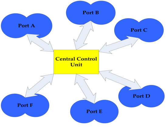
Figure 1.
Schematic diagram for the ports’ commitment controlled system.
2.1. Technical Constraints
In this research, three main technical constraints are considered.
2.1.1. Electrical Interconnection Constraint ()
The first constraint is the electrical interconnection of the port to the controlled unified power network.
2.1.2. Voltage Constraint ()
Voltage deviation ( is a vital significant constraint, which it is essential to check to be certain it is within a definite limit. It is the maximum voltage deviation between corresponding bus and nominal voltage (). The voltage difference should be kept within the limit of ± 5% to avert any failure or damage in the electrical system [28].
where = 1 p.u.
2.1.3. Frequency Constraint ()
Frequency deficiency () is the maximum frequency variance between the bus and the nominal frequency (). Deviance in frequency, will possibly lead to a catastrophe, so the maximum satisfactory variation is ± 1% [29]. It is denoted as
where = 1 p.u.
The frequency difference essential be studied to be established within a definite range.
2.2. Economic and Environmental Factors
2.2.1. Transmission Power Loss Factor ()
Transmission Lines (T.L.) are the connecting lines between ports and/or the central control unit, which enable the transportation of electrical power. They are wide-open to many losses such as copper loss, which affect the transmitting energy. Copper Loss depends on the length and the impedance of the line between the ports and/or the central control unit. It is calculated as follows:
where and are the T.L. power loss and transmitted power (in kW), respectively. is the impedance of the transmission line. is the line voltage (in V). is the power loss penalty cost, while is the transmitted electrical energy between ports (in MWh).
2.2.2. Electricity Price (Generation and Maintenance) Factor ()
One of the main significant factors in the optimal connecting the ports is the Electricity Price (). As each port may have its own electrical dispersed generators. The owner can sell the electricity to the near interconnected ports for a different price. The difference in cost is determined according to the type of the generation source, its capital and running cost, and the deviation of the peak hour. The electrical power station equipments and installation are considered as part of the capital cost. They are calculated, and divided on the permissible life time of the station for each MWh, considering a flat interest. The maintenance cost and storage battery replacement can be considered from the source running cost. The factor is analysed as follows:
where is the penalty cost, while Egem is the generated electrical energy (in MWh).
2.2.3. CO2 Emission Factor ()
Each port may have its private electrical energy generation resources. Each resource has different environmental effect. The unified network penalizes the ports according to the level of CO2 emission. Less CO2 emission will lead to minimizing the penalties [30], which constructs , not only an environmental factor, but also an economic one. It is calculated as follows:
where is the CO2 emission penalty cost. and depend on the type of energy generation resource. is the consumed electrical energy (in MWh).
3. Hybrid Particle Swarm Optimization
The eco-ports’ smart optimal commitment problem can be deliberated as a multi-objective problem. The first target in this problem is to determine the best electrical power generation and consuming units to minimize the CO2 emission cost through the interconnected networks (seaports) under different operating conditions. The second target is to obtain the optimal exchanged and transmitted energy capacities between the assigned ports under the frame of the technical constraints to achieve the best economic and environmental conditions. Due to the critical necessity to obtain the optimal solution, an optimization technique is addressed. Hybrid (weighted-discrete) Particle Swarm Optimization Technique (HPSOT) is applied to obtain the optimal inner distribution inside each network and the appropriate alternative connections to withstand operating conditions.
Nowadays, Particle Swarm Optimization (PSO) technique can be considered one of the main base-stones in optimization techniques. In 1995, an evolutionary computation procedure was anticipated by Kennedy, a social-psychologist, and Eberhart, an electrical engineer [31]. PSO is a population-oriented optimization procedure that was initially motivated by the sociological conduct related with bird grouping and fish clustering. Hybrid PSO technique, developed in this work, is constructed from the original weighted PSO and the discrete PSO [32] as shown in Figure 2. Discrete PSO (DPSO) technique is utilized for obtaining the best fitted supplier and consumer ports’ combination. The optimum transmitted energy capacities are determined based on the weighted PSO technique.
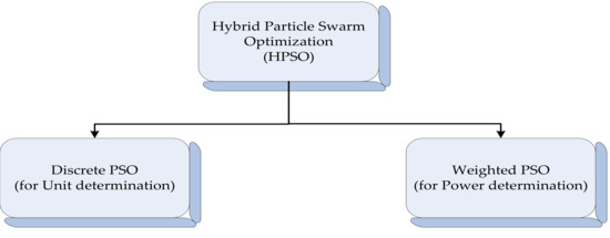
Figure 2.
Hybrid Particle Swarm Optimization (HPSO) descriptive block diagram.
The core of the PSO procedure is to preserve inhabitants of particles, referred to as a “swarm”, where each particle signifies a possible result to the objective (cost) function concerned. Each element in the swarm will memorize its present situation that is obtained by the assessment of the objective function, rate, and the best situation visited throughout its flying excursion in the search space referred to as “individual best situation”. Here it is meant by the individual best situation, the one that produces the highest objective value for that particle. For a minimization assignment, the location, having a smaller fitness value, is observed to as a higher fitness. Also the best location visited by all particles is remembered, i.e., the best location between all individual best locations referred to as “global best location”. The particles of the DPSO are expected to transport the problem search domain in discrete rather than continuous time steps. At each time step (iteration) the rate of each particle is adapted using its current velocity and its distance from individual best and global best locations according to Equations (11)–(15). Figure 3 represents a demo for the position update of swarm particles in a 3-D [33]. The basic and general flowchart of HPSOT is displayed in Figure 4, however the details will be discussed in Section 4 “Simulation and Results”. The HPSOT flowchart can be summarized as follows: (1) the data of the seaports’ network are entered into the program; (2) create an initial swarm, with a random distribution and random initial velocities for both discrete and weighted PSO; (3) check the system constraints and conditions; (4) set the global best position of all particles based on the system fitness functions; (5) calculate a velocity vector for each particle, using the particle’s memory and the knowledge gained by the swarm; (6) update the position of each particle, using its velocity vector and previous position; (7) check the system constraints and conditions; (8) update the personal best position of each particle, and the global best position of all particles based on the system fitness functions; (9) go to step 5 and repeat until convergence, or the termination criterion is met.
where is the jth velocity component real value at iteration k + 1, while is the jth velocity component integer value at iteration k + 1. is random value between 0 and 1. is the current position in the jth dimension at iteration k. and are the cognition and social factors, that are usually set to 2.0. and are the personal and global best location in the jth dimension at iteration k, respectively. is the time step. means if and only if, and . is the cost function. It is a minimum solution objective function.
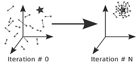
Figure 3.
The position update of particles in a 3-D [33].
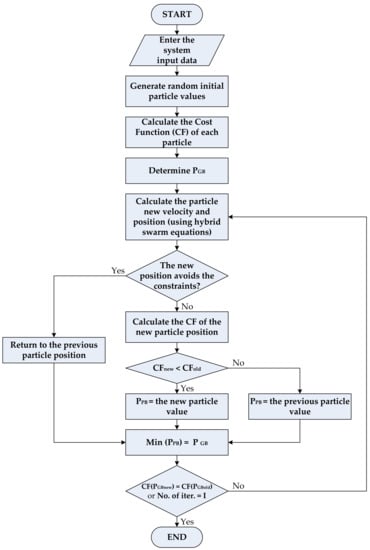
Figure 4.
Hybrid Particle Swarm Optimization (HPSO) flowchart.
4. Simulation and Results
The discussed research project is suggested to be applied to a tested modal, which is constructed from six Egyptian seaports. The six ports are Damietta, Alexandria, and El Dekheila on Mediteranean and Port Said, Suez, and Sokhna port on Suez canal and Red sea as illustrated in Figure 5. The simplified single line diagram of the ports’ connected system is presented in Figure 6. The data of the six ports, including the ports’ demand electrical energy (Edem in MWh), the daily average active and reactive power demand (Pdem in MW and Qdem in MVAR respectively) and the connected transmission lines’ data (Ric, Xic, Bcapic in pu) are presented in Table 1 and Table 2. Two PV electrical power generation units can possibly be built in Damietta and Sokhna ports, with the energy capacities clarified in Table 3. The average energy capacities of the PV units are calculated utilizing [7] formulas, the solar insolation map of Egypt that is shown in Figure 7, and a fifth of the areas of both ports. Based on HPSOT, the optimum energy flow distributions between the six ports are studied in both winter and summer seasons.
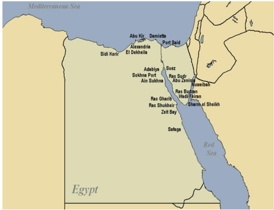
Figure 5.
Egyptian seaport map [34].
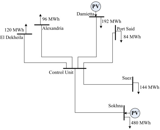
Figure 6.
Simplified single line diagram of the six ports’ connected system.

Table 1.
The data of the six studied Egyptian seaports [35].

Table 2.
The transmission lines’ impedance, active and reactive demand power of the six studied Egyptian seaports.

Table 3.
The impact of the average daily PV generated and consumed energy of the six studied Egyptian seaport on the CO2 emission.
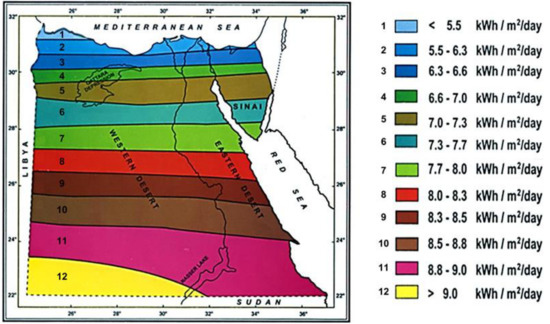
Figure 7.
Solar insolation map of Egypt. [36].
The HPSOT algorithm is programmed, utilizing the system data which are given in both Table 1 and Table 2, and the average energy capacities of the PV units. It is constructed from two sets of solution particles, which are the discrete set () and the continuous set (). The swarm particle in each set is clarified as
where and are the xth particle in the discrete and continuous sets respectively, at iteration k. and are indicators for the thermal and PV electrical power generation of bus i respectively, while is the indicator of the injected power to bus i. are set to be either 0 in case of non –connected or non-operated term, or 1 otherwise. is the indicator of the transmitted power between bus i and bus j. It can be equal to 0 if there is not transmitted power, 1 if the power is transmitted from bus i to bus j, or −1 if the power is transmitted to bus i from bus j.
The number of particles, in each set, is chosen to be 40 per iteration (XP = 40 particles/set/iteration). Each suggested solution particle is subjected to fulfil some conditions and obey some constraints which are as follows: in Equation (1), in Equation (3), and in Equation (5). To calculate the required variables (, for and , the following non-linear power flow equations, shown in Equations (18)–(21), are used, in addition to ETAP load flow program.
where are the real and reactive power injected to each bus, while are the real and reactive power flow from bus i to bus j respectively. is the admittance magnitude of the line connected bus i and bus j. is the admittance angle of the line connected bus i and bus j. is the angle of the bus i voltage. is the total line charging susceptance. is the impedance of the line connected bus i and the control unit.
The solution particle, which fulfils the conditions and constraints, is upgraded to achieve the discrete and continuous fitness (cost) functions (, ),
illustrated in Equations (23)–(24). should reach zero, while should be minimized.
where are the PV and thermal electrical generated power of bus i, respectively. equals to 0.11 $/kWh. equals to 0.1 $/kWh (for thermal power generation sources) or 0.12 $/kWh (for PV electrical generation sources). is considered to be 6.8 $/kWh (for thermal sources) or 0.4 $/kWh (for PV source).
5. Discussion
As the PV electrical generated energy varies according to the season, the optimal energy flow distributions between the six Egyptian ports are represented in Figure 8 and Figure 9, and Table 3, for both winter and summer seasons. The total average daily PV generated, consumed and excess energy of the six studied Egyptian seaports, for both summer and winter are displayed in Table 4. In this research, the required consumed energy of each port and the power losses of the transmission lines are assumed to be fixed during the various seasons.
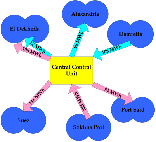
Figure 8.
The average daily electrical energy flow through the studied system in Winter (the turquoise colour for Damietta energy distribution and the pink colour for Sokhna port energy distribution).
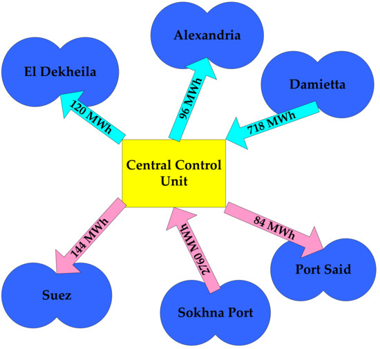
Figure 9.
The average daily electrical energy flow through the studied system in Summer (the turquoise colour for Damietta energy distribution and the pink colour for Sokhna port energy distribution).

Table 4.
The total average daily PV generated, consumed and excess energy of the six studied Egyptian seaports.
Table 3 clarifies the calculated average daily CO2 emission (in kg CO2), released from the equivalent PV electrical energy that can replace the fossil fuel electrical energy generation. The considered mean CO2 emission rates of electricity generation from PV and fossil fuels are 50 kg CO2/MWh and 850 kg CO2/MWh, respectively. The obsolete CO2 emissions (in kg CO2), due to fossil fuel electrical power sources’ replacement by PV ones, is displayed in the last column of Table 3. The average daily equivalent PV-CO2 emission compared to the eliminated CO2 emission of the six Egyptian seaports is presented in Figure 10. The total obsolete CO2 emissions can reach 892,800 kg CO2/day, indicating the competence and the effectiveness of the simulated research project. This reduction in CO2 emissions can be processed to improve its positive impact on the rate of climate change and the greenhouse effect.
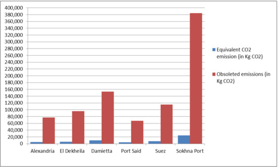
Figure 10.
The average daily equivalent PV-CO2 emission compared to the eliminated CO2 emission in the six Egyptian seaports.
6. Conclusions
This paper represents a suggested study for ports’ electrical power systems optimal commitment based on an eco-friendly concept targeting the green port environment to form a decarbonized unified power network for ports. The optimum interconnection between the ports’ electrical network is based on Hybrid Particle Swarm Optimization Technique (HPSOT). The HPSOT consists of discrete PSO for assigning both supplier and consumer ports, and the direction of the power flow, while weighted PSO is for determining the transmitted power between the two ports. The optimal ports’ commitment is designed to work under certain technical constraints and fulfil the optimum economic and environmental conditions. The technical constraints are electrical interconnection, voltage, and frequency constraints. Transmission power loss, electricity price, and CO2 emission are the studied environmental and economic factors. The developed work is tested on a sample of Egyptian ports. The studied sample consists of six seaports. Three of the six ports are Mediterranean ports which are Damietta, Alexandria, and El Dekheila while the others are on the Suez canal and the red sea which are Port Said, Suez, and Sokhna. Both Damietta and Sokhna ports are suggested to have PV electrical power generation units to cover their electrical power demand and optimally share the excess power with the other connected ports. The average clean electrical generated energy can vary from 1365 MWh/day in winter to 4150 MWh/day in summer. It is supposed to supply the overall energy demand of the whole controlled unified power network which is 1116 MWh/day. Based on the objectivity of this research, the equivalent reduction in CO2 emission is equal to 892,800 kg CO2, which is the difference in the CO2 emission from PV generated energy and its equivalent from fossil fuel sources. This reduction in CO2 emissions is equivalent to 94% of its fossil fuels CO2 emissions for the same electrical energy generation. It means a positive impact on the greenhouse effect and climate changes.
Author Contributions
The three authors contribute in the whole work. Alsnosy Balbaa works on data curation, funding acquisition, project administration, and resources. Rania A. Swief works on methodology, software, validation, and writing—original draft. Noha H. El-Amary works on conceptualization, formal analysis, investigation, supervision, and writing—review & editing.
Funding
This research received no external funding.
Conflicts of Interest
The authors declare no conflict of interest.
Nomenclature
| the electrical interconnection constraint. | |
| the voltage constraint. | |
| the voltage deviation. | |
| the bus voltage. | |
| the nominal voltage. | |
| the maximum limit of the voltage deviation. | |
| the frequency constraint. | |
| the frequency deficiency. | |
| the bus frequency. | |
| the nominal frequency. | |
| the maximum satisfactory frequency variation. | |
| the transmission power loss factor. | |
| the electricity price (generation and maintenance) factor. | |
| the CO2 emission factor. | |
| the transmission line power loss (in kW). | |
| the transmission line transmitted power (in kW). | |
| the impedance of transmission line. | |
| the line voltage (in V). | |
| the power loss penalty cost. | |
| the transmitted electrical energy between ports (in MWh). | |
| the Electricity Price penalty cost. | |
| the generated electrical energy (in MWh). | |
| the CO2 emission penalty cost. | |
| the consumed electrical energy (in MWh). | |
| the jth velocity component real value at iteration k + 1. | |
| the jth velocity component integer value at iteration k + 1. | |
| a random value between 0 and 1. | |
| the current position in the jth dimension at iteration k. | |
| and | the cognition and social factors, that are usually set to 2.0. |
| and | the personal and global best location in the jth dimension at iteration k. |
| the time step. | |
| the cost function. It is a minimum solution objective function. | |
| Edem | the ports’ demand electrical energy (in MWh). |
References
- ESMIG. Available online: https://esmig.eu/page/20-20-20-goals (accessed on 20 March 2019).
- Sawik, B.; Faulin, J.; Perez-Bernabeu, E. A multicriteria analysis for the green VRP: A case discussion for the distribution problem of a Spanish retailer. Transp. Res. Procedia 2017, 22, 305–313. [Google Scholar] [CrossRef]
- Sawik, B.; Faulin, J.; Perez-Bernabeu, E. Multi-criteria optimization for fleet size with environmental aspects. Transp. Res. Procedia 2017, 27, 61–68. [Google Scholar] [CrossRef]
- Serrano-Hernandez, A.; Faulin, J.; Hirsch, P.; Fikar, C. Agent-based simulation for horizontal cooperation in logistics and transportation: From the individual to the grand coalition. Simul. Model. Pract. Theory 2018, 85, 47–59. [Google Scholar] [CrossRef]
- El-Amary, N.H.; Balbaa, A. Green energy seaport suggestion for sustainable development in Damietta port, Egypt. WIT Trans. Ecol. Environ. 2017, 214, 67–77. [Google Scholar]
- Balbaa, A.; El-Amary, N.H. Environmental sustainable in seaports through electrical power scheduling. In Proceedings of the International Maritime Transport & Logistics Conference “Marlog7” entitled: Innovation in Ports “The Gateway of the Future”, Alexandria, Egypt, 18–20 March 2018. [Google Scholar]
- El-Amary, N.H.; Balbaa, A.; Swief, R.A.; Abdel-Salam, T.S. A reconfigured whale optimization technique (RWOT) for renewable electrical energy optimal scheduling impact on sustainable development applied to Damietta seaport, Egypt. Energies 2018, 11, 535. [Google Scholar] [CrossRef]
- Tumuluru, V.K.; Tsang, D.H. A two-stage approach for network constrained unit commitment problem with demand response. IEEE Trans. Smart Grid 2018, 9, 1175–1183. [Google Scholar] [CrossRef]
- Abujarad, S.Y.; Mustafa, M.W.; Jamian, J.J. Recent approaches of unit commitment in the presence of intermittent renewable energy resources: A review. Renew. Sustain. Energy Rev. 2017, 70, 215–223. [Google Scholar] [CrossRef]
- Cobos, N.G.; Arroyo, J.M.; Alguacil, N.; Street, A. Network-constrained unit commitment under significant wind penetration: A multistage robust approach with non-fixed recourse. Appl. Energy 2018, 232, 489–503. [Google Scholar] [CrossRef]
- Xiong, P.; Jirutitijaroen, P.; Singh, C. A distributionally robust optimization model for unit commitment considering uncertain wind power generation. IEEE Trans. Power Syst. 2017, 32, 39–49. [Google Scholar] [CrossRef]
- Aghaei, J.; Agelidis, V.G.; Charwand, M.; Raeisi, F.; Ahmadi, A.; Nezhad, A.E.; Heidari, A. Optimal robust unit commitment of CHP plants in electricity markets using information gap decision theory. IEEE Trans. Smart Grid 2017, 8, 2296–2304. [Google Scholar] [CrossRef]
- Pandžić, H.; Dvorkin, Y.; Qiu, T.; Wang, Y.; Kirschen, D.S. Toward cost-efficient and reliable unit commitment under uncertainty. IEEE Trans. Power Syst. 2016, 31, 970–982. [Google Scholar] [CrossRef]
- Zhang, N.; Kang, C.; Xia, Q.; Ding, Y.; Huang, Y.; Sun, R.; Huang, J.; Bai, J. A convex model of risk-based unit commitment for day-ahead market clearing considering wind power uncertainty. IEEE Trans. Power Syst. 2015, 30, 1582–1592. [Google Scholar] [CrossRef]
- Osório, G.J.; Lujano-Rojas, J.M.; Matias, J.C.O.; Catalão, J.P.S. A new scenario generation-based method to solve the unit commitment problem with high penetration of renewable energies. Int. J. Electr. Power Energy Syst. 2015, 64, 1063–1072. [Google Scholar] [CrossRef]
- ElAzab, H.A.I.; Swief, R.A.; El-Amary, N.H.; Temraz, H.K. Unit commitment towards decarbonized network facing fixed and stochastic resources applying water cycle optimization. Energies 2018, 11, 1140. [Google Scholar] [CrossRef]
- Makeen, P.; Swief, R.A.; Abdel-Salam, T.S.; El-Amary, N.H. Smart hybrid micro-grid integration for optimal power sharing-based water cycle optimization technique. Energies 2018, 11, 1083. [Google Scholar] [CrossRef]
- Liu, Y.; Fan, R.; Terzija, V. Power system restoration: A literature review from 2006 to 2016. J. Mod. Power Syst. Clean Energy 2016, 4, 332–341. [Google Scholar] [CrossRef]
- DeHaan, M.P.; Likins, A.K.; Vidal, S.K. Automatically Generating System Restoration Order for Network Recovery. U.S. Patent 8,667,096, 4 March 2014. [Google Scholar]
- Golshani, A.; Sun, W.; Zhou, Q.; Zheng, Q.P.; Hou, Y. Incorporating wind energy in power system restoration planning. IEEE Trans. Smart Grid 2017, 10, 16–28. [Google Scholar] [CrossRef]
- Sun, L.; Wang, X.; Liu, W.; Lin, Z.; Wen, F.; Ang, S.P.; Salam, M.A. Optimisation model for power system restoration with support from electric vehicles employing battery swapping. IET Gener. Transm. Distrib. 2016, 10, 771–779. [Google Scholar] [CrossRef]
- Riahinia, S.; Abbaspour, A.; Farzin, H.; Khalili, S. A dynamic programing-based framework for distribution system restoration considering load uncertainties. Int. Trans. Electr. Energy Syst. 2017, 27, e2448. [Google Scholar] [CrossRef]
- Che, L.; Zhang, X.; Shahidehpour, M.; Alabdulwahab, A.; Abusorrah, A. Optimal interconnection planning of community microgrids with renewable energy sources. IEEE Trans. Smart Grid 2017, 8, 1054–1063. [Google Scholar] [CrossRef]
- You, S.; Hadley, S.W.; Shankar, M.; Liu, Y. Co-optimizing generation and transmission expansion with wind power in large-scale power grids—Implementation in the US Eastern interconnection. Elect. Power Syst. Res. 2016, 133, 209–218. [Google Scholar] [CrossRef]
- Jian, L.; Zheng, Y.; Xiao, X.; Chan, C.C. Optimal scheduling for vehicle-to-grid operation with stochastic connection of plug-in electric vehicles to smart grid. Appl. Energy 2015, 146, 150–161. [Google Scholar] [CrossRef]
- Koad, R.B.; Zobaa, A.F.; El-Shahat, A. A novel MPPT algorithm based on particle swarm optimization for photovoltaic systems. IEEE Trans. Sustain. Energy 2017, 8, 468–476. [Google Scholar] [CrossRef]
- Taherkhani, M.; Safabakhsh, R. A novel stability-based adaptive inertia weight for particle swarm optimization. Appl. Soft Comput. 2016, 38, 281–295. [Google Scholar] [CrossRef]
- IEEE. IEEE Standard Service Conditions for Power System Communications Apparatus; Institute of Electrical and Electronics Engineers, Inc.: Piscataway, NJ, USA, 30 August 1968; No. 281; Available online: https://standards.ieee.org/standard/281-1968.html (accessed on 10 October 2018).
- Verma, R.; Sahu, P. Frequency fluctuation in power system: Sources, control and minimizing techniques. Int. J. Adv. Res. Electr. Electron. Instrum. Eng. 2014, 3. [Google Scholar] [CrossRef]
- Vasudevan, S.; Farooq, S.; Karimi, I.A.; Saeys, M.; Quah, M.C.; Agrawal, R. Energy penalty estimates for CO2 capture: Comparison between fuel types and capture-combustion modes. Energy 2016, 103, 709–714. [Google Scholar] [CrossRef]
- Kennedy, J.; Eberhart, R. Particle swarm optimization. In Proceedings of the IEEE Neural Networks Conference, Perth, WA, Australia, 27 November–1 December 1995; IEEE Service Center: Piscataway, NJ, USA, 1995; pp. 1942–1948. [Google Scholar]
- El-Amary, N.H.; Mostafa, Y.G.; Mansour, M.M.; Mekhamer, S.F.; Badr, M.A.L. Phasor measurement units’ allocation using discrete particle swarm for voltage stability monitoring. In Proceedings of the IEEE Electrical Power and Energy Conference 2008, Vancouver, BC, Canada, 6–7 October 2008. [Google Scholar]
- Particle Swarm Optimization (PSO). Available online: https://esa.github.io/pagmo2/docs/cpp/algorithms/pso.html (accessed on 12 October 2018).
- Canal Shipping Agencies. Available online: http://www.seabird-marine.com/ship%20agency%20services.htm (accessed on 10 October 2018).
- The Egyptian Port’s Capacity. Available online: http://www.mts.gov.eg/en/content/275/1-83-The-Egyptian-Ports-Capacity (accessed on 4 August 2018).
- Hegazy, I.R.; Moustafa, W.S. Sustainable residential sector in Egypt: Performance estimation of a grid-connected photovoltaic system for Dar Misr housing project as a case study. J. Archit. Eng. 2018, 24. [Google Scholar] [CrossRef]
© 2019 by the authors. Licensee MDPI, Basel, Switzerland. This article is an open access article distributed under the terms and conditions of the Creative Commons Attribution (CC BY) license (http://creativecommons.org/licenses/by/4.0/).