1. Introduction
Three-dimensional (3D) rendering technology is widely used in various virtual reality fields. It is essential for investigating and monitoring the most important geomorphological features of natural areas. The rich potential of 3D rendering is also utilized in areas that rely on geographical data, for example, evacuation planning [
1], geospatial data exploration and analysis [
2,
3,
4], navigation in urban areas [
5,
6], visualization of spatial data quality [
7], educational games [
8], and urban planning [
9]. It is also possible to use the interaction between other digital information for 3D terrain rendering for disaster prediction and in (geographic) education.
In these areas, a digital elevation model (DEM) is generally used for geographical data. The DEM data are a collection of height values obtained from the uniformly sampled information about the height of the ground surface. Typically, the height data are measured using a 3D scanning technique [
10]. Due to the increasing resolution of the DEM and its ortho-photo texture data, more memory and computing power are required even when using current high-end graphics processing units (GPUs). Thus, for the past several decades, the increasing computational requirements for real-time rendering of massive terrain data is a considerable concern for geo-scientists and researchers.
Recently, graphic devices are rapidly evolving to handle large scale data. These industrial developments offer solutions to handle large-scale terrain, but they require the replacement of large quantities of existing equipment. Generally, a lot of rare materials are used for GPU production. The rare materials used for the graphic adapter are more varied and consumed in larger amounts than the GPU. Typically, gold and silver are used for connections and switches, and tantalum and palladium are used for transistors and capacitors. In addition, various materials such as aluminum, tin, zinc, fiberglass, platinum, and copper are used. Frequent replacement results in a significant amount of environmental waste. In order to render the large-scale terrain data with existing graphic equipment, many algorithms that use GPUs for acceleration [
11,
12,
13] have been studied.
To overcome this problem, a number of continuous level-of-detail (CLOD) methods [
14,
15] are being investigated. In general, terrain data is becoming more and more sophisticated according to the needs of users and these methods usually represent terrain with multi-resolution quadrangle grids. This can efficiently reduce the number of triangles. The quadtree data structure and rendering technique [
16,
17,
18], further referred to as the ‘quadtree technique’, is one of the most well-known hierarchical data structures that are used to efficiently control the shape of multi-resolution grids in two-dimensional (2D) space.
Graphics hardware has also been improved in performance to enable such large terrain data to be processed in real time as the hardware architecture changes. Therefore, in order to render the latest DEM data in real time, it is common to replace the graphics hardware to new generation graphic hardware. Instead of replacing such hardware, the proposed method enables high quality software-based rendering of sophisticated data in real-time so that the rendering performance of the next generation GPU can be expected in the existing graphics hardware. This can delay the GPU’s generation replacement, which can prevent wasteful GPU replacement.
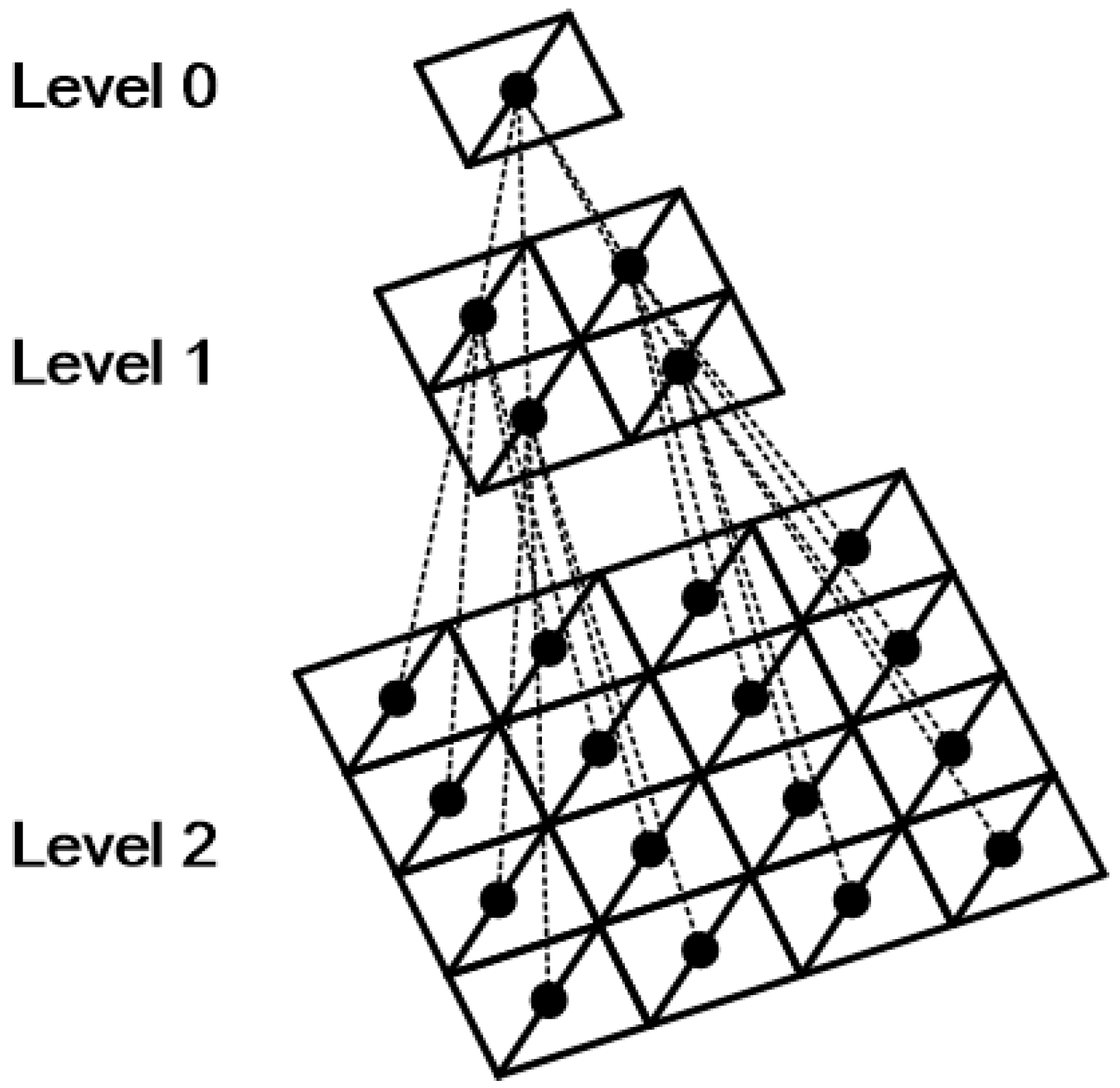
Since a 3D terrain mesh is based on triangles, one can triangulate the topography pointed by each node of quadtree in the form of square patch with two triangles as shown in the
Figure 1. The quadtree triangulation [
17] is the process of triangulating a rough terrain with several quad patches, and flat terrain with single quad patch. By reflecting the height of the terrain at each vertex, we can triangulate a simplified terrain mesh with compact number of vertices.
Tessellation [
19] or ray-casting [
20,
21,
22] are quadtree-based terrain rendering methods that have been recently introduced. Using base mesh generation, they provide a faster rendering speed than quadtree triangulation methods [
23]. However, the recursive process while traversing the quadtree is not appropriate for GPU parallel processing.
Level-of-detail (LOD) methods using multi-resolution grids [
24,
25] that are based on the distance between the camera and the object are easy to expand for use in out-of-core algorithms. Moreover, they do not need complex computation to avoid cracks and to select LOD, so they are appropriate for being used on GPUs. However, unlike quadtree-based methods, they cannot support compact geometry.
We propose a GPU-friendly quadtree triangulation approach that reuses the terrain geometry of a previous frame. Our method performs LOD selection using two stream output (SO) buffers in the geometry shader stage, and photo tree search operations are performed in parallel on each triangle unit.
The proposed quadtree approach can be executed on the GPU and speeds up the LOD selection per node, especially with a large number of triangular patches. Moreover, since the LOD selection is only performed on the GPU, it is effective when the CPU plays a relatively large role in applications or rendering systems.
In general, the existing GPU quadtree triangulation has the disadvantage of regenerating the terrain whenever the viewing condition changes. If the frame rate is not constant, blinking of the screen may occur due to a temporary decrease in the frame rate. This is worse when there is a significant difference between the best-case and worst-case scenarios. Since the proposed method utilizes frame-to-frame coherency, it is possible to obtain a constant frame rate in comparison to conventional methods [
26]. By reusing the mesh data used in the previous frame, the computation is efficiently reduced.
Cracks occur when neighboring patches have different LODs, as illustrated in
Figure 2. Therefore, it is necessary to inspect the detailed steps of the neighbor patches to split or merge the patches to prevent cracks. In existing CPU-based methods, we solve this problem by using propagation method [
27,
28].
However, when parallel processing is in progress on the GPU, it is not possible to access the geometry data being processed by other threads. Thus, in the proposed method, each thread calculates and saves the detailed steps of the adjacent patches without just storing their detailed steps when calculating the detailed steps of one patch. This may result in additional computation and a slight increase in memory consumption, but it is easy to determine if cracks occur because each thread can see the difference in the detailed steps from its neighboring patches. Unlike existing methods, which require additional passes or access to neighboring nodes in the event of a crack, the proposed method can eliminate cracks in the detailed step selection process.
In order to facilitate detailed step selection, the result output to the SO buffer should be used as the input value of the next step. At this time, bidirectional data transfer between the system memory and the GPU memory is required. Such data transmission is costly, and in particular, it takes a long time to increase the amount of data to be transmitted. In this paper, we discuss the process by which we reduced the geometric data by compressing the details of one triangle and neighboring triangles to one vertex.
Typically, when using quadtree triangulation, it is necessary to check and choose the appropriate detailed steps recursively from the root node to the leaf node. This method does not utilize the information of the previous frame because the entire mesh needs to be newly generated in every frame as the observation condition is changed. In order to solve this problem, we propose a method for merging or splitting a rectangular patch by fetching the mesh used in the previous frame and process it as a single operation without a recursive operation. This reduces the amount of data transferred between the system memory and the GPU memory, which occurs every time the root node is checked from the child node, and decreases the number of operations that perform the transmission, thereby greatly reducing the overall amount of geometric data transfer.
Graphics adapters are a very important hardware in computing machines. They are also bulky, and many materials are used in their production. As 3D technologies are rapidly evolving, the replacement cycle of these graphics adapters is getting shorter due to under-performance, not malfunction. The graphic device contains the GPU and video RAM or is included in the CPU. This replacement of the graphic device consumes a large amount of rare material compared to other parts and is not easy to recycle. The proposed method aims to catch up with the development of modern 3D technology in software, and aims at delaying the replacement period of graphics adapter. This reduces the waste of material due to the dismantling of the graphics adapter and enables longer hardware usage. Using the proposed method, it is proven that the minimum fps (frames-per-second), which caused the major equipment replacement in the 3D terrain rendering field, can be extended by reusing the previous frame to extend the life cycle of the used product.
In
Section 2, we introduce related work. The main algorithm will be described in detail in
Section 3. In
Section 4, the experimental results are given and discussion of GPU upgrade cycle with those results is provided. We conclude our work in
Section 5.
2. Related Work
Researches on sustainability using GPUs in large computing systems [
29,
30] focus primarily on high performance computing (HPC). In general, software acceleration can replace hardware replacement by using parallel processing of existing GPUs in existing computing systems or personal computers.
In order to render high-resolution DEM data in real time, a rendering acceleration method using simplification of terrain geometry and a non-geometric rendering method is often used. Typically, geometry-based accelerations are used for regular grid-based hierarchy [
26,
27,
28] and triangulated irregular network (TIN)-based hierarchy [
16].
The DEM data are the data in which the terrain is stored with a regular sampling interval. Therefore, the data can be easily expressed by the meshing process using a regular grid. However, the higher the resolution, the longer the processing time that is needed because the number of necessary grids is increased. In a traditional environment using a CPU, we used a hierarchical structure, such as a triangle binary tree [
31] or a restricted quadtree [
17], to adjust the number of triangles. This enabled us to achieve the subdivision of a square or triangle in the same way, which is advantageous for eliminating flat areas or out-of-sight triangles that do not require subdivision. The triangle-binary tree method is better at saving the storage space of the geometry data [
26,
31] than the quadtree triangulation methods.
Methods using geometry caches efficiently render the terrain using GPU capabilities [
32,
33,
34]. Chunk LOD [
35] reduces the computation required for LOD selection by using a geometry cache in the form of a chunk of specific region geometry. Similar methods are based on batched dynamic adaptive mesh (BDAM) [
33,
34,
36] and the seamless patch method [
37], which use TIN as a geometry cache.
Since the introduction of the programmable GPU pipeline, GPU-based rendering techniques—such as geometry image warping [
38]—have been introduced. The vertex relocation method [
39] is a GPU-based parallel warping method that uses elastic force [
40] between the vertices of the terrain mesh. These methods primarily extract the main features from the DEM data to simplify the mesh. Consequently, they can render the terrain faster than the CPU by using the GPU.
However, due to the limitation of available memory space, hybrid methods [
22,
23,
41,
42] with out-of-core based algorithms have been widely used [
24,
43,
44]. The significant problem of out-of-core based algorithms is reducing the transmission time to transfer data to the GPU memory. To solve this problem, GPU-based geometry decompression [
45] techniques that use decompressed data from the GPU have been proposed, as have methods that use an image hierarchy, such as a geometry clipmap [
24]. In addition, LOD methods using indexes are introduced by methods using primitive characteristics [
44] such as triangle strip.
Continuing GPU advances have resulted in research that speeds up triangle rasterization faster than simplifying terrain, while improving efficiency with fast, simple simplification techniques [
24,
37,
46]. These methods have an advantage of expanding to out-of-core and can perform fast rendering by utilizing parallel processing of GPU. However, in general, only distance-based LOD is performed, so there are many disadvantages in data compared to methods considering memory efficiency and roughness of the terrain.
Recently, ray-casting [
13,
20,
21,
23,
47,
48] techniques using the rendered image domain have been studied to solve the problem of increased computation and data transmission due to large geometry. However, the computation time is long with these techniques because far away geometry or even empty pixels (e.g., the sky) are expensive to compute without giving any contribution to the rendered image. In the ray-casting technique, pyramidal displacement mapping is accelerated by reducing the computation of empty space using a photo tree. The bimodal empty space skipping technique combines a bounding box using geometry and pyramidal displacement mapping to provide high-quality images that have the advantages of simple operations and ray-based rendering techniques, which are also advantages of geometry-based rendering techniques. While it is difficult to query high-frequency surface details for operations such as collision detection, these methods provide a high-quality image with less geometry than stored in the base mesh by utilizing displacement mapping.
3. GPU-Based Dynamic Adaptive Mesh
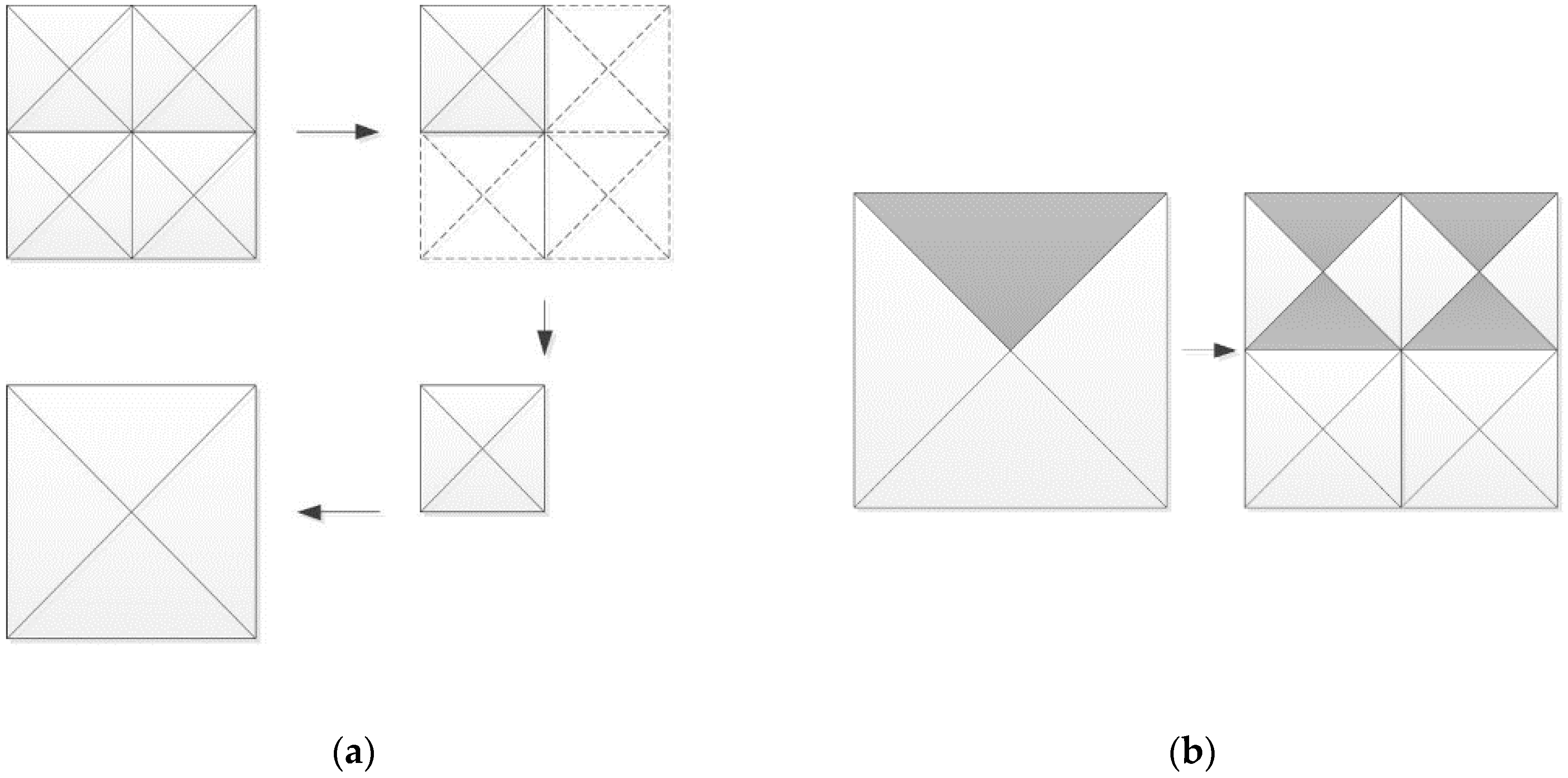
Quadtree triangulation is a method that is used to restructure a topographic mesh composed of a regular grid using a hierarchical data structure. Each node in the quadtree corresponds to one regular grid patch that comprises the terrain mesh. If it is necessary to represent a patch in more detail, it is possible to quad the patch into four child nodes in order to refer to the height of the terrain with more vertices. Furthermore, if it can be simplified, it is possible to reduce the number of polygons by combining the four adjacent patches into one patch of a parent node.
Generally, a DEM dataset has tera-bytes of data size. Since the DEM data is larger than GPU memory, some of these data are stored in a file on the server or hard disk, and only necessary parts are selected and uploaded to the GPU in real time for rendering [
49]. In this case, the DEM data to be rendered is a two-dimensional height-field. The more triangles (polygons) that make up a mesh, the higher GPU power is needed to render. Therefore, when rendering on the screen in real time, you should be able to effectively reduce the triangle number without introducing artifacts. The existing mesh simplification technique has been mainly used to reduce the number of triangles on the CPU. The goal of the proposed method is to accelerate this task using GPU parallel processing to reduce the rendering time.
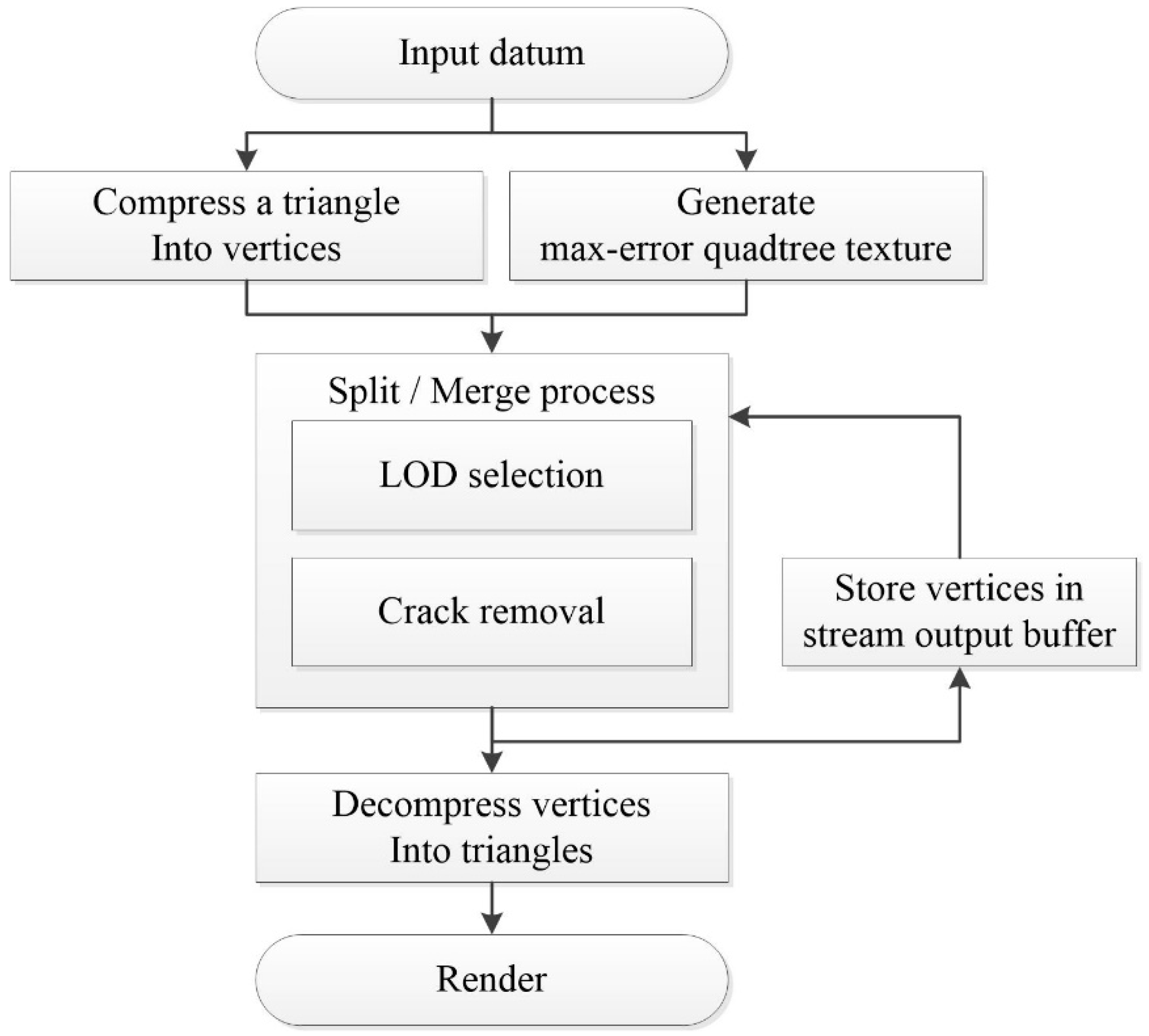
The procedure of the proposed method is shown in
Figure 3. In the preprocessing step, the geometric error value for selecting detail level is stored in the quadtree. This photo tree is created in a texture pyramid format for use with the GPU. On GPUs, geometry shaders can be used to quickly create or delete polygons. The stream output stage also allows the GPU to quickly generate the terrain mesh using recursive operations that are appropriate for the photo tree.
However, it is difficult to measure the accuracy of quadtree-based methods because the amount of computation that is required to search the tree to find the appropriate detail step depends on the observation conditions. Therefore, there is a large difference in the operation speed between the best-case and worst-case scenarios. To solve this problem, the proposed method provides a way to update the current terrain mesh using the geometry data used in the previous frame in the SO buffer, since—generally—the viewing conditions in the previous frame do not change much in the next frame in real-time rendering in continuous views. Usually, artifacts such as geo-popping and frame-drop usually occur while rendering in continuous viewing condition. When the part of the terrain mesh used in the previous frame is reused, the terrain necessary for the current frame can be generated using very few operations.
Because the geometry data to be written on the buffer increases, the transmission time between buffers also increases when the SO is used. Therefore, this study proposes a method to reduce the amount of geometry data by compressing each triangle consisting of a rectangular patch into one vertex. This reduces the transmission time, since this method uses less memory than conventional methods. Moreover, it does not require any additional data transmission because the GPU renders immediately after the decompression.
Sudden change of scene is not sensitive because the overall render setting changes. In these conditions, the GPU buffers are re-initialized and the temporal frame-of-reference is started anew. However, in successive scenes, problems such as geo-popping and frame drop occur. While rendering continuous terrain scenes, these problems are very critical.
In this case, applications which provide scene continuity via continuous rendering of terrain—such as 3D walkthrough simulations, flight simulations and zoom-in/zoom-out for 3D topographic mapping—there is no significant change in the detail level between the frames because the viewing condition between the frames does change significantly. Therefore, the terrain to be represented in the current frame can be generated by a single execution of the split/merge operation on most of the grids used in the previous frame. This reduces the number of irregularly repeated quadtree search operations to one. Thus, the frames only perform the LOD selection once, and the terrain mesh can be constantly maintained and the rendering speed can be improved.
Because of their guarantee for scene continuity, flight simulations and novel continuity-based 3D topography mapping [
50] are our target applications for technique validation in this article. With advances in adopting continuous-scale rendering and interaction, we envisage that our technique will serve as a basis for future systems in professional applications, such as natural hazard planning, urban planning, and geo-information systems (GISs).
This study proposes a temporal coherent method that reuses the geometry data used in previous frames. It is implemented by using double vertex buffer swapping of the input vertex buffer and the stream output buffer after triangulation processing on the GPU. These two buffers are bound to the input and SO stages of the GPU rendering pipeline. The geometry shader splits or merges the input data, and the results are saved for use in the next frame when the detail level of the terrain mesh is selected. The split and merge processes are performed for each triangle in order to select the detail level of the terrain mesh. After the detail selection, the compressed data are restored as geometry data using the decompression stage in the geometry shader; the data are then rendered immediately by the pixel shader.
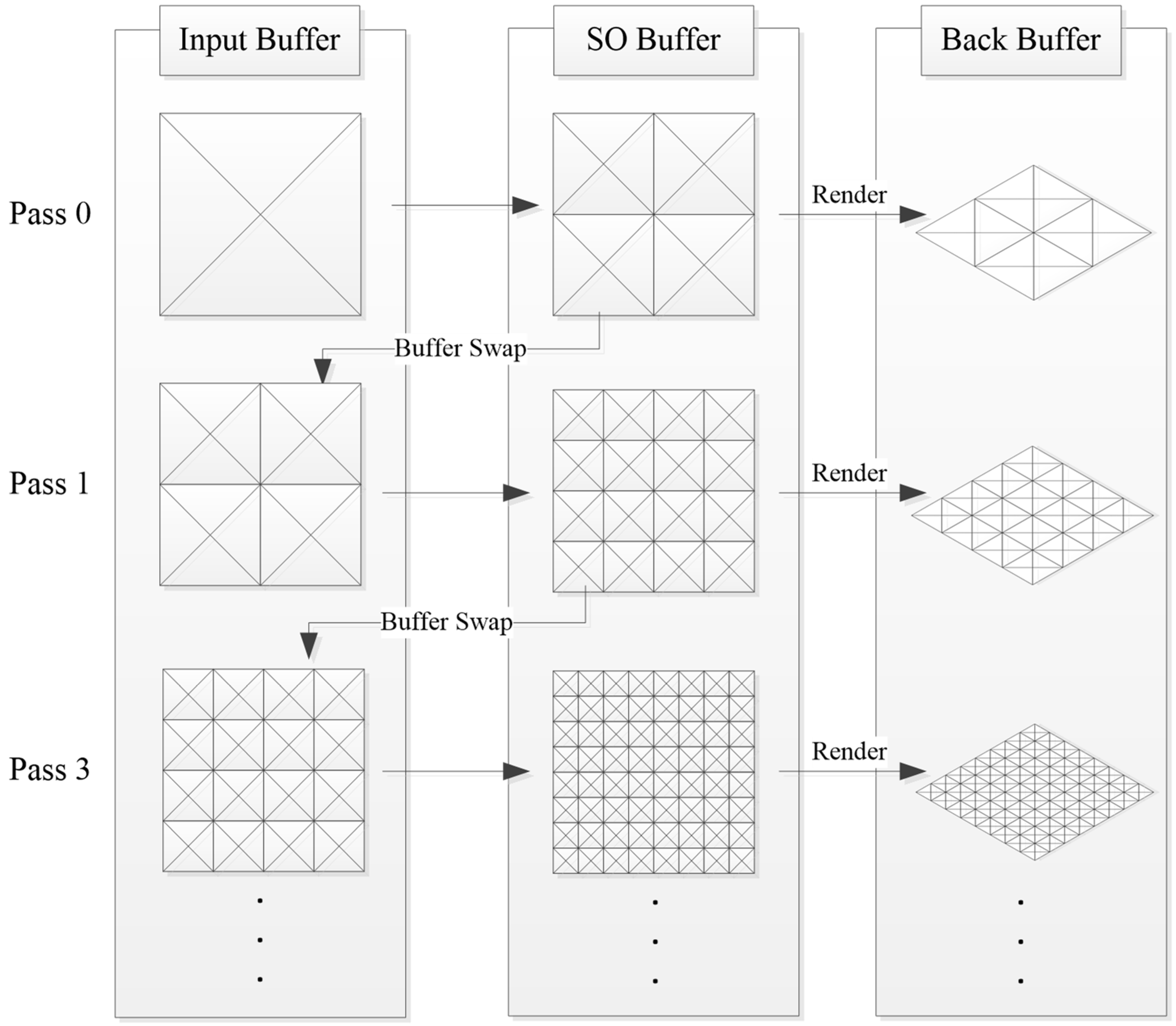
3.1. Terrain Mesh Generation Using Buffer Swapping
This section describes how to accelerate the triangulation of the terrain mesh using two buffers effectively. As shown in
Figure 4, a rectangular patch corresponding to the root node is the input data for the input buffer. If the detail level of the root node is not appropriate for representing the final terrain mesh, subdividing it into four child nodes will result in a more detailed terrain mesh than is possible with the root node. The child nodes are stored on the SO buffer after subdivision of the root node. We directly render the rectangular patches in the SO buffer to the back buffer of the screen. To reuse the child nodes in the SO buffer, our method swaps the SO buffer with the input buffer. By repeating these steps in consecutive frames, the terrain mesh will be generated to the adequate detail level, as shown in
Figure 4.
However, repeating the splitting step may increase the vertices and decrease the rendering speed. Thus, if the patch reached its adequate detail level, it will stop subdividing itself. Moreover, if the patch needs to be simplified, our method merges the adjacent four patches that share the same parent node. A detailed description of the merging and splitting steps will be presented in the following section.
3.2. Merging and Spliting Steps in the GPU Rendering Pipeline
The methods that are used to render DEM data using the quadrangle patch are represented with four triangles. Usually, two triangles are used to represent the quadrangle patch with a triangle-binary tree [
31]. Quadtree-based triangulation methods are based on the quadrangle with four triangles. In comparison to the quadtree triangulation with four triangles, using two triangles per patch can reduce the size of the vertex buffer. However, one disadvantage is that many tree searches must be performed, since the depth of the tree is twice that of the quadtree. Our method focuses on decreasing the data transmission time while traversing the tree.
In general, a quadtree stores two triangles in one node, whereas in the case of a triangle-binary tree, one node stores only one triangle. Thus, in the case of a triangle-binary tree, the depth of the tree is two times deeper than that of the quadtree while both of them triangulate the same terrain mesh. Therefore, the quadtree-based method usually performs less traversal than triangle-binary tree methods. Thus, we used the quadrangle patch that is represented with four triangles.
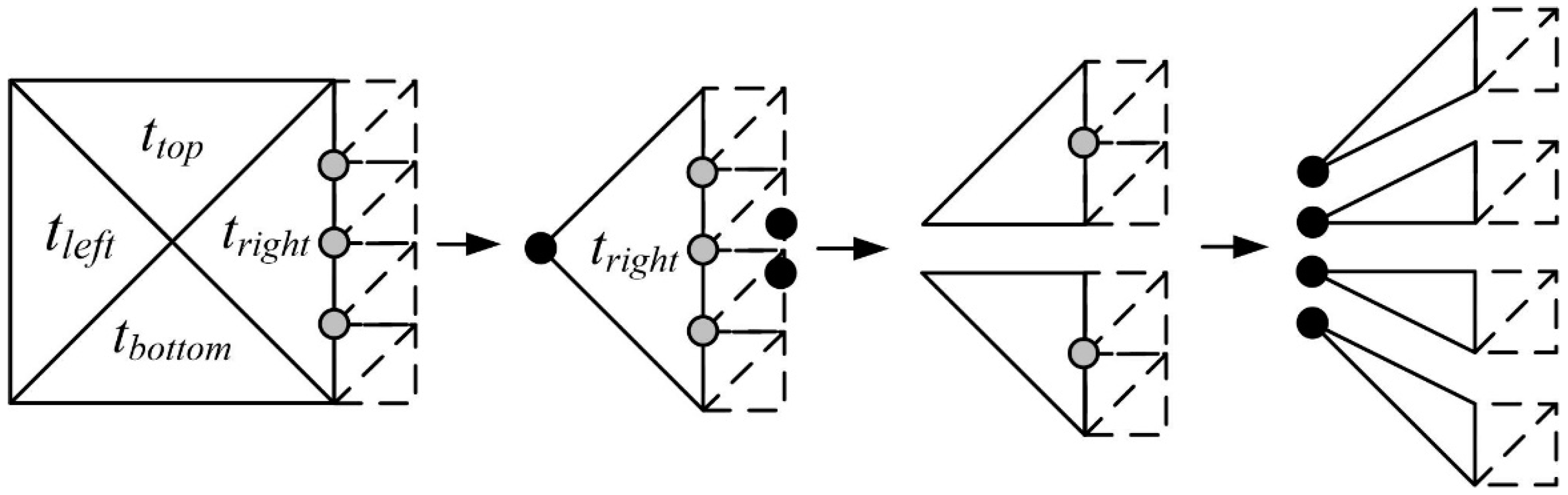
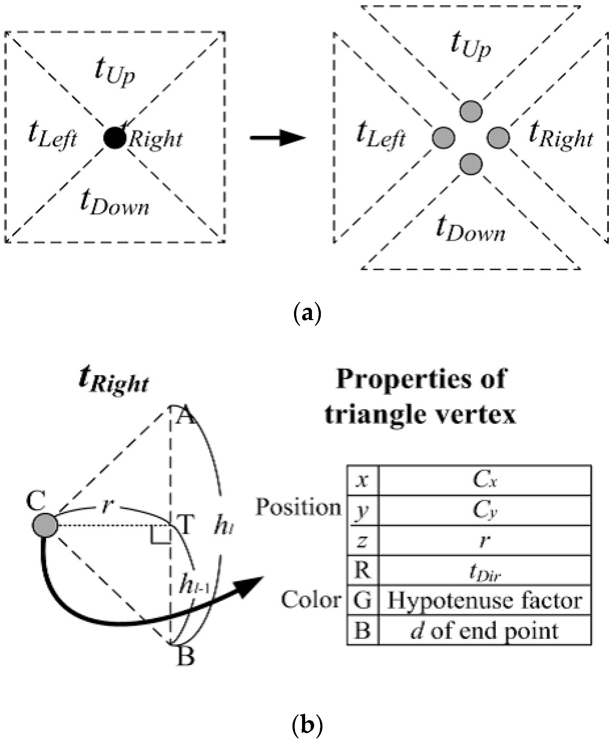
Our method presents an efficient parallel crack removal technique that uses the direction of the four triangles. To remove the cracks, the proposed method uses the triangulation method that utilizes four triangular patches for easy parallel processing for the forced splitting of neighbor nodes [
28]. Each of the triangles constituting one patch have different type values (up, down, left, right) for each direction based on the center point, as shown in
Figure 5.
The detail levels are selected by the merging or splitting of these patches on the geometry shader. As shown in
Figure 5, the cracks are generated by the wedge when the detail levels between the neighbor patches are different. In the LOD method that transforms the geometry, cracking is the most serious problem and a solution must be suggested. In the proposed method, the detail levels of the neighbor nodes are stored in each triangle, and the triangle is separated to prevent the crack (
Figure 5).
The gray dots shown in
Figure 5 are the T-vertices that cause the cracks. The triangle is divided with respect to the T-vertex, not to generate the crack on the edge of a specific patch. This triangle splitting step is executed on the larger side of the neighbor patches. As shown in
Figure 6, the divided values are indexed by the order of division on the edge. At this time, the vertex position, detail level, type, and index should be stored for each triangle.
The proposed algorithm merges or splits the patch used in the previous frame to select the detail level. If simplification is required, as shown in
Figure 6a, the child patches are merged to the corresponding patches of the parent node. The split that divides the patch into four parts is applied when detailing is required, as shown in
Figure 6b. Since each triangle has an index as well as a type, the index value should be maintained after the merging step or the splitting step has been executed.
The merging process is performed with the triangles from the four child patches that have an identical type and that share the edge with the parent patch. Triangles other than these are deleted if they are not necessary after the merging process is completed. The vertices of the remaining triangles are moved to the center of the patch if they do not share the edge with the parent patches. Then, the proposed method checks the details of the neighboring patches and merges the triangles with the indexes to be merged to create the final patch.
For the splitting process, as shown in
Figure 6b, one triangle is divided into a corresponding type and the other type with the opposite direction to create a ribbon shape. Thus, a patch is finally split into four triangles. In the proposed method, triangles constituting a child node or a parent node of one node can receive the same edge information from a triangle of the previous frame. Therefore, index information, which can be lost due to deletion or creation of triangles, is retained. The geometry shader can effectively perform the parallel crack removal process with the edge information from the previous frame.
3.3. Geometry Compression
Since the proposed method writes the contents processed by the GPU to the buffer during the splitting/merging process, more data are stored in each vertex. The data transmission time between the input buffer and the SO buffer will be longer. This section explains how to accelerate the rendering process by reducing the amount of data and the number of required computations.
The geometry shader can handle both triangles and vertices for the input primitive. If the required information of a triangle is stored in a vertex, the transmission and processing time for the three vertices can be reduced to one. To do this, the position, detail level, type, and index information of the triangle vertices has to be stored in one vertex. Usually a vertex can store lots of floating-point variables. However, storing the properties of these triangles in a vertex as they are, requires many variables. This increases the capacity of the vertex buffer, which is a waste of memory and increases transmission time. These deficiencies can be solved through the compression in
Figure 7. The vertex to be compressed consists of six floating point variables. In our method we used position and color channel, widely known as
x,
y,
z,
r, g, and
b. The
x and
y fields of the position channel store the (
x, y) coordinates of the midpoint vertex C.
z field stores the length of the perpendicular line down the hypotenuse from the point C, which is shown as
r in
Figure 7. The
r and
g channel stores the type and hypothenuse factors (expressing the length of triangle’s hypothenuse). By using hypothenuse factor,
r and position of C, we can easily decompress the triangle. The
b channel stores
d, which represents the depth of the quadtree. Using the
r, index and type value, it is easy to generate the triangles comprising the patch centered on
x and
y. These vertices can also be merged or split with less computation than is required for merging or splitting the triangles.
3.4. Error Metric for LOD Selection
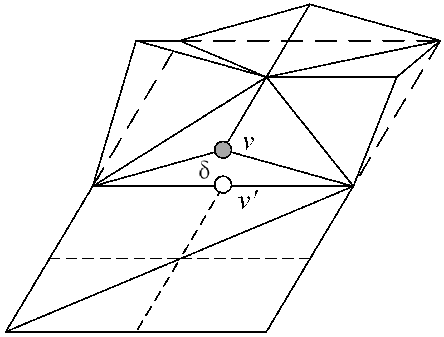
In the proposed method, the detail level of the regular grid constituting the terrain is selected based on the camera distance and surface roughness. Both the camera distance and surface roughness can be considered by using the maximum geometric error, which can be used to calculate the standard error in the screen space.
In the proposed algorithm, a regular grid can be converted into a regular grid of the parent node by merging with four neighboring nodes or it can be converted into a regular grid of the child node by subdividing it into four child grids. In this case, the geometric error used for the detail level selection is measured as δ1-5, which is the height difference between the vertices of the child nodes and the edge of the parent node. If this geometric error is greater than the threshold value specified in the screen space, the patch should be split. In the proposed method, only an error of less than 0.5 pixel is allowed for an image that does not cause an error in the pixel unit. This error value ensures that the geometry does not affect other pixels due to errors in the rasterizer step.
When applying the perspective projection, the geometric error of the child node in the projection space can be larger than the error in the parent node because it is closer to the viewpoint, even though the child node has a smaller error value than the parent node. Therefore, the proposed method postulates a strictly monotonic relationship between the child node and the parent node [
17]. In other words, the parent node should not have a smaller maximum error than the child node.
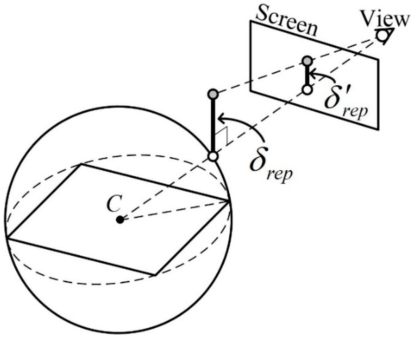
To select the detail level that satisfies these conditions, the proposed method set the maximum value of the distortion that an error can have to be
δrep, which is the maximum geometric error value nearest to the observer using the bounding sphere of the grid, as shown in
Figure 8. The representative error value
δrep of a node is the maximum error value of the node and the lower nodes. The line connecting C, the center of the bounding sphere, to the observation point is called the ‘line direction’. In the plane where the intersection between the direction and the bounding sphere touches, it is assumed that there is a line passing through the intersection with the length of
δrep in a specific direction. The maximum distortion,
δ’rep, which measures the length of the line on the screen space, can be obtained by projection to screen space.
3.5. Converting Vertices into Terrain Mesh and Texturing
As a result of the LOD selection, many vertices are generated. To prepare the next frame, the data have to be stored in the SO buffer. The resulting frame has to be rendered with vertex data in the SO buffer before swapping the SO buffer and the input buffer. Therefore, before swapping the buffers, the vertices in the SO buffer will be decompressed as a triangle patch. This process will be performed in the geometry shader stage. After generating the terrain patch, it is necessary to set the height from DEM, translate each vertex, and set the uv coordinate for the texture mapping. These geometries will represent the final terrain mesh. By performing this step in the geometry shader, our method uses the entire process on the GPU, and there is no data transmission between the main memory on the CPU and the video memory on the GPU.
4. Experimental Results
In order to prove the efficiency of the proposed method we compared nVidia GTX 560, 660, 760, and 960 graphical devices, which are commonly used in PCs using terrain rendering services. We measured the frames per second (fps) of conventional quadtree-based methods [
18,
26,
35] and compared the proposed method with previous-generation graphics cards.
All the experiments were performed on a consumer PC equipped with Intel CoreTM i5-2500 3.3 GHz CPU, 16 GB of main memory. We used DirectX 11 and Shader Model 5.0 as the graphics application programming interface (API). Since the limitation of the texture size of the graphic hardware is 81922 and the size of the dataset has to be (2d + 1)2, we scaled the resolutions of the datasets as 40972 to use the largest quadtree. Therefore, the depth of the quadtree, d, will be 12. The viewport size was set to 1600 × 900 pixels.
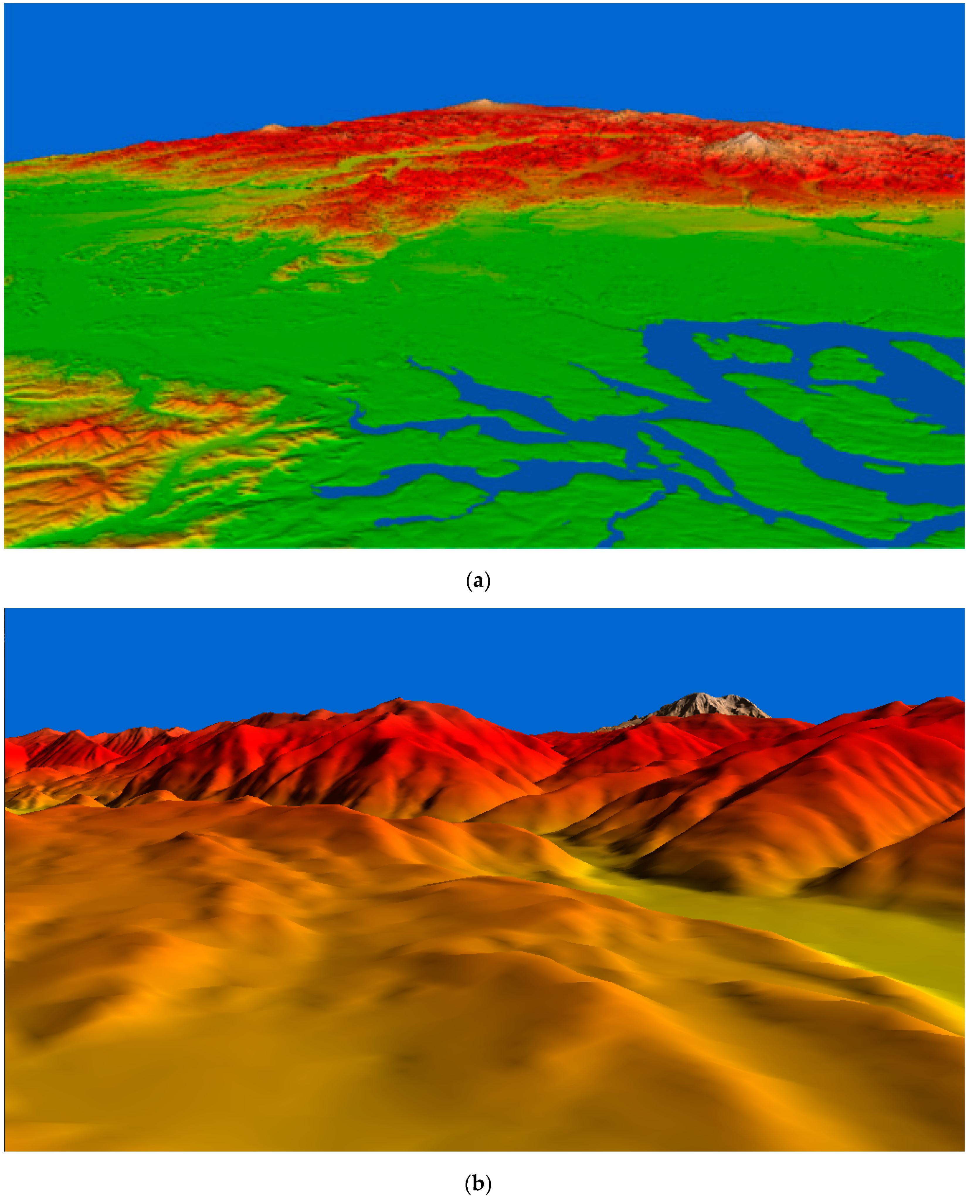
The proposed method has improved the rendering speed and increased the amount of data for transmission in comparison to other methods. Generally, in 3D rendering, terrain is mainly used in two types of viewing conditions. The first is a flight view where you can observe the terrain freely from various locations. The second one is a walk-through view that observes the viewpoint of the person on the ground. To prove the efficiency of the proposed method, we compared the rendering speed and the amount of data transmission with other research in two different viewing conditions, as shown in
Figure 9. Generally, the flight view is called (a) far view because it can view the terrain vertically from the ground to the ground. The walk-through view is called a (b) near view because it is close to the ground and looks horizontally to the ground. Therefore, we set the viewing condition to meet these characteristics.
The far view viewing condition, shown in
Figure 7a, is widely used on 3D terrain rendering such as flight view in flight simulation and geo-surface tools. This viewing condition usually focuses on observing the terrain surfaces. It has to render a wide region on the screen. In the far view, the camera coordinates are usually located in the sky. Since the height data is perpendicular to the ground plane, the maximum screen distortion
δ’rep is small in the far view condition. Thus, the terrain mesh can be simplified with this condition in comparison to the near view. Moreover, the far view uses fewer triangles than the near view.
The near view is the viewing condition in which the camera is located near the ground. This viewing condition usually used for simulation such as virtual reality, gaming, ground-level navigation (e.g., disaster- and evacuation planning). Most 3D walk-through simulations use the near view.
Figure 7b shows the rendering result of the Puget Sound data with the near view condition. Because the viewing direction is horizontal to the ground plane, the maximum screen distortion
δ’rep appears to be larger in the near view condition than it does in the far view condition. Thus, more polygons are required to represent the terrain mesh in the near view condition than in the far view condition.
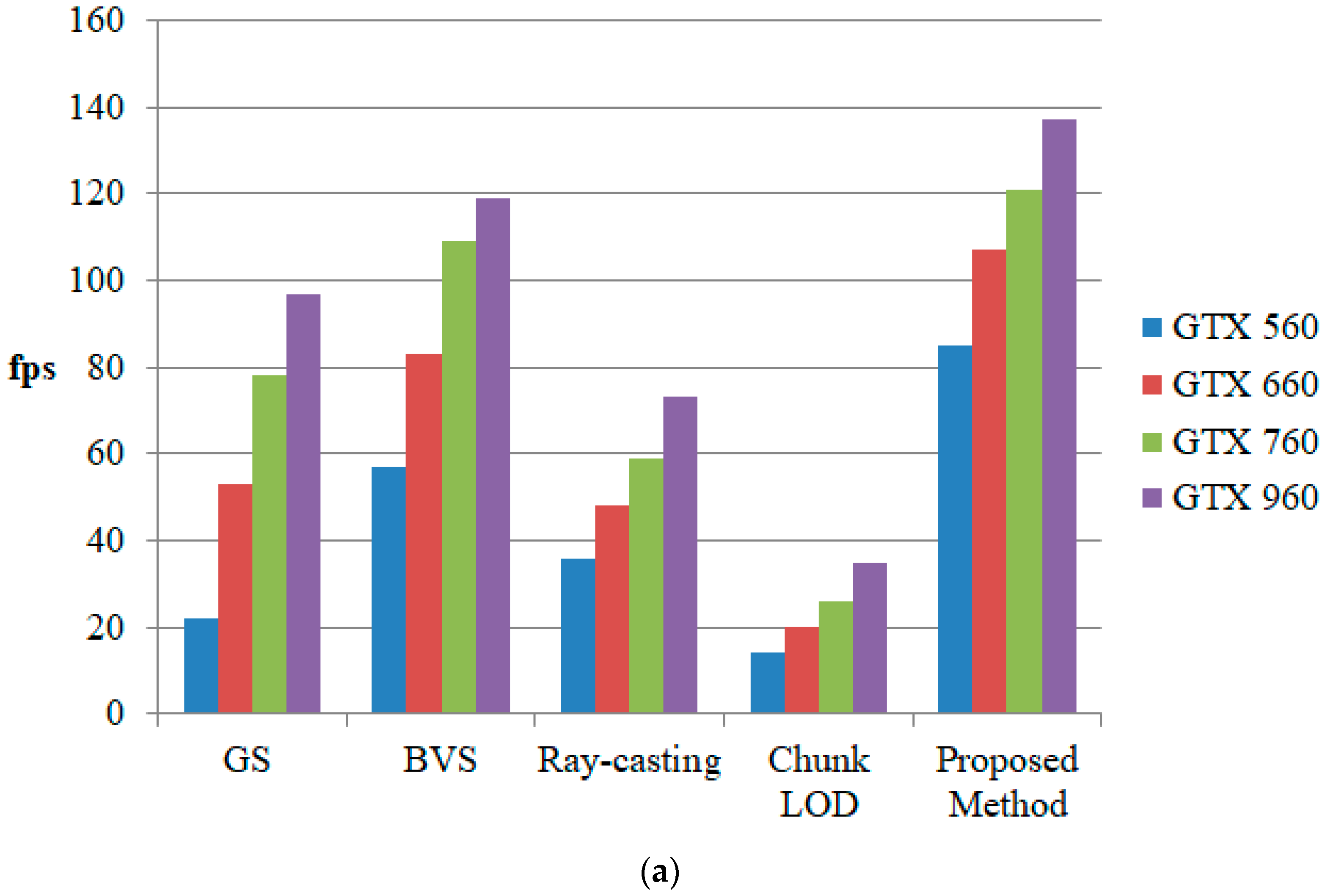
Figure 10 shows a comparison of the rendering speed of the proposed method with various existing quadtree-based terrain rendering methods. To measure the efficiency of the proposed method, we tested different GPU lineups of different generations within the past decade. This assessment allows for a realistic estimation of older hardware value and applicability. The GTX 560 was released in early 2010, and the GTX 960 was released in mid-2014.
For a fair comparison, the screen error metric of the other methods was set equal to the metric of the proposed method. In two previous studies, we used geometry splitting (GS) [
18] and bimodal vertex splitting (BVS) [
26] as quadtree triangulation methods. The ray-casting [
20] method also uses a quadtree as a maximum mipmap [
21]. Chunk LOD [
35,
37] uses a fixed geometry chunk with a quadtree to reduce the tree traversal cost. As seen in
Figure 10, the proposed method had a faster rendering speed than the other methods. In general, the ray-casting method is slow, but it is barely affected by the viewing conditions. Mesh-based methods [
18,
26,
35] are fast, but they are significantly affected by the polygon counts when the viewing conditions are different. However, the proposed method is faster in rendering and is less affected by viewing conditions. This is because, unlike other methods, the proposed method only performs the quadtree search operation once.
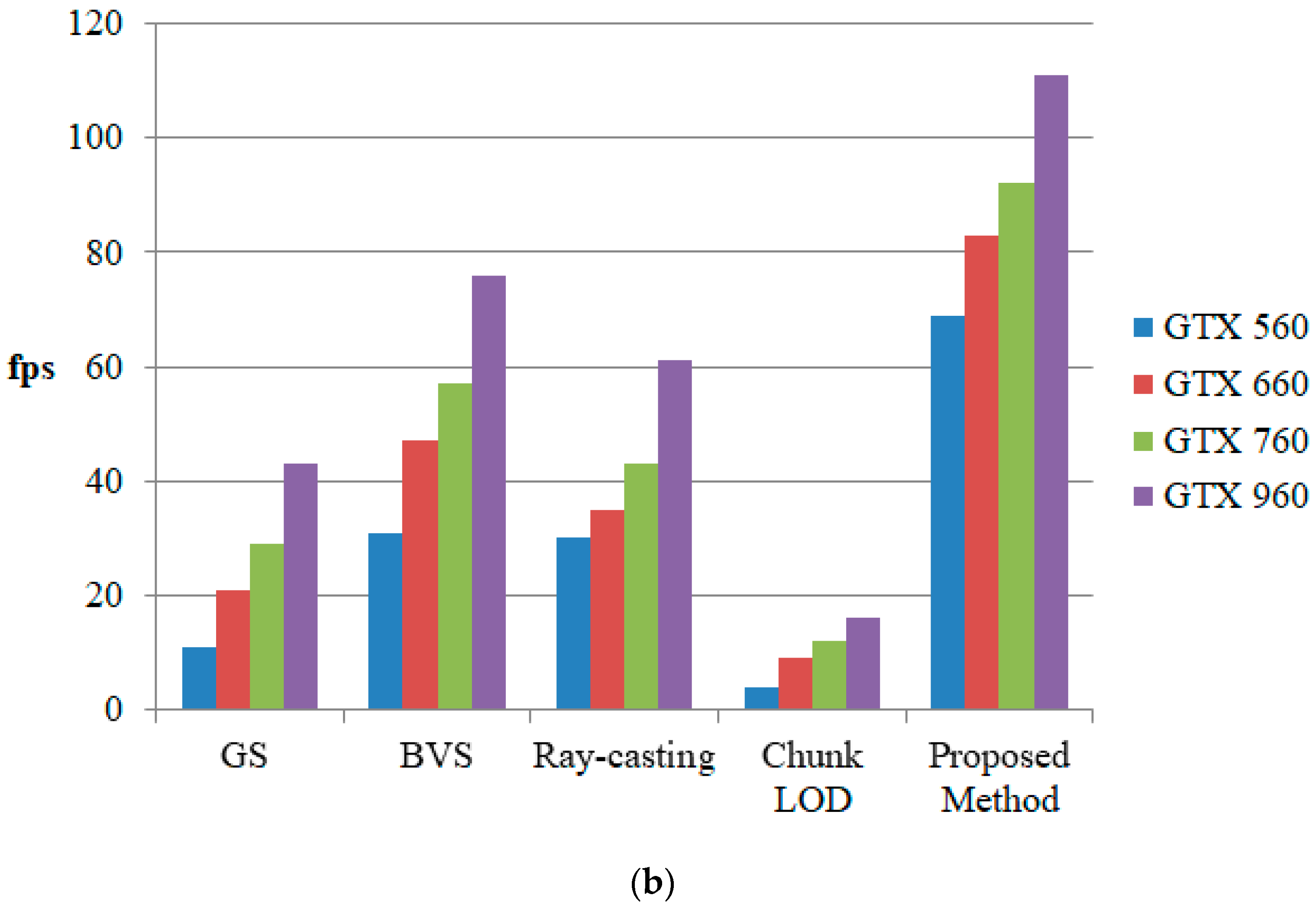
Figure 11 shows the performance comparison in continuous viewing conditions. As seen in
Figure 11a, using GTX960 in BVS shows similar performance while using our method in GTX 560 in (b). BVS is one of the fastest conventional quadtree-based methods. The proposed method shows a similar or faster rendering speed to BVS, even with previous generations of GPUs. This is similar to far view and near view, and in near view where performance artifact such as frame drop is easy to occur, graphic performance similar to GTX 960 is shown on GTX 560 which is the third generation GPU. This can effectively replace the generational replacement of the GPU.
Table 1 shows a comparison of the number of vertices processed using the GS and BVS methods and the proposed method. The GS and BVS methods use vertices in the SO buffer to perform tree traversal in the GPU. The GS method needs to search the quadtree from the root node to the leaf nodes twice, using vertex splitting and triangle splitting. Since the depth of the quadtree is 12 in the experiment, the GS method performed the splitting process with SO 24 times. BVS reduced the computing cost by using two different types of vertex splitting in a single pass. However, it still has to traverse the quadtree 12 times. If the vertex finds its proper detail level, then it stops the splitting process and just by-passes the input vertex to the SO buffer. Thus, many vertices are repeatedly by-passed in the SO buffer. The proposed method uses the vertices from a previous frame. As seen in the results presented in
Table 1, the proposed method can reduce the amount of data and the operation speed by eliminating the iterative operation using the vertex data that is used in the previous frame. Reducing the amount of computation when generating the same image due to the reuse of the vertex brings benefits in terms of both saving and longevity of computing power.
According to the experimental results, the speed improvement was greater in the near view condition than the far view condition. This is because the more detailed terrain should be rendered at a closer range, so the amount of geometry data for the tree-search increases. Also, the difference between the lowest fps and the highest fps was smaller in the continuous view while using proposed method. However, the proposed method reuses compressed vertex data, so the amount of transmitting data is small, but the amount of geometric data to be transformed in GPU is large. Therefore, the proposed method minimizes the impact of viewing conditions and decreases the rendering speed.
The implication of these results is that the software approach can be used rather than relying on the replacement cycle of the hardware in order to render the larger terrain more realistically. In general, a graphic device requires a lot of material on its own, and it has built-in video RAM as well as additional devices such as a display port and a sound device. There is also a case where it is embedded in a CPU or a motherboard. These graphic devices are capable of operating for a very long period of time. Replacing such a graphic device causes unnecessary waste of materials. Even if the existing graphic device is not broken, it is mostly replaced with a performance problem. The latest graphic devices can render real-time terrain data that could not be rendered in previous generations. The proposed method proved that, instead of replacing the hardware, software can render the latest terrain data in real time in four-year-old hardware, which can solve the problem of replacing the GPU every year. Also, the proposed method improves the rendering speed, which not only slows down the GPU replacement time but also overcomes GPU overload. By reusing the buffer used in the previous frame, you can reduce the GPU overload for duplicate operations, which is another reason to extend the lifetime of the GPU. For this reason, delaying the replacement of GPUs, which is often done annually, not only reduces the consumption of rare materials used in GPUs such as gold and silver, but also slows down the replacement time of CPUs and motherboards. Also, reducing the computational complexity of the GPU rendering processes, as proposed by our method, has the advantage of preventing the overheating problem, extending the physical lifetime, and reducing power consumption.


