Article

Improvement of MPPT Control Performance Using Fuzzy Control and VGPI in the PV System for Micro Grid

1
Department of Computer Engineering, Sunchon National University, 255 Jungang-ro, Suncheon-city Jeollanam do 57922, Korea
2
Department of Data Informatics, Korea Maritime and Ocean University, Busan 49112, Korea
3
Department of Electrical Engineering, Sunchon National University, 255 Jungang-ro, Suncheon-city Jeollanam do 57922, Korea
*
Author to whom correspondence should be addressed.
Sustainability 2019, 11(21), 5891; https://doi.org/10.3390/su11215891
Submission received: 13 August 2019 / Revised: 14 October 2019 / Accepted: 15 October 2019 / Published: 23 October 2019
(This article belongs to the Collection Microgrids: The Path to Sustainability)

Abstract

:
This paper proposes the method for maximum power point tracking (MPPT) of the photovoltaic (PV) system. The conventional PI controller controls the system with fixed gains. Conventional PI controllers with fixed gains cannot satisfy both transient and steady-state. Therefore, to overcome the shortcomings of conventional PI controllers, this paper presents the variable gain proportional integral (VGPI) controllers that control the gain value of PI controllers using fuzzy control. Inputs of fuzzy control used in the VGPI controller are the slope from the voltage-power characteristics of the PV module. This paper designs fuzzy control’s membership functions and rule bases using the characteristics that the slope decreases in size, as it approaches the maximum power point and increases as it gets farther. In addition, the gain of the PI controller is adjusted to increase in transient-state and decrease in steady-state in order to improve the error in steady-state and the tracking speed of maximum power point of the PV system. The performance of the VGPI controller has experimented in cases where the solar radiation is constant and the solar radiation varies, to compare with the performance of the P&O method, which is traditionally used most often in MPPT, and the performance of the PI controller, which is used most commonly in the industry field. Finally, the results from the experiment are presented and the results are analyzed.

Graphical Abstract

1. Introduction

Renewable energy is drawing much attention as an energy source that can replace fossil fuels. Solar energy is the most representative renewable energy and an infinite, eco-friendly energy but is highly dependent on temperature and solar radiation. Temperature affects voltage, and solar radiation affects current [1,2,3]. Temperature and solar radiation have a direct impact on solar power output and, in particular, cause a change in MPP (maximum power point). In order to track the MPP of the PV system efficiently, an appropriate DC-DC converter and a tracking algorithm (method) must be integrated and configured, and the following conditions must be satisfied [4]:
  • Fast tracking response (transient response).
  • No vibration around the MPP (steady-state response).
  • Response performance against insolation and temperature change.
  • Simple structure and low cost.
Typical methods for MPPT (maximum power point tracking) are the Constant Voltage method using a fixed ratio of the open voltage, P&O (Perturb & Observe) method using power and voltage perturbation, and IncCond (Incremental Conductance) method using slope and conductance that can be obtained in the current ( I pv )-voltage ( V pv ) and power (P)-voltage ( V pv ) curves [5,6,7,8,9,10,11,12,13]. In addition, These methods use reference voltage [14,15,16,17,18,19,20,21], reference current [22,23], or duty ratio [24] for maximum power point tracking. Among them, the P&O method has the advantages of simple structure and low calculation, whereas the IncCond method has the advantage of tracking the MPP faster and more accurately than the P&O. These methods are most generally used for the MPPT of the photovoltaic (PV) system due to the aforesaid advantages. Since the P&O and IncCond methods track the MPP while varying the voltage or current by a fixed size, however, vibration may occur near the MPP, and performance may deteriorate; thus rapidly changing the solar radiation conditions. Although used to solve these problems, artificial neural networks also have problems such as long learning time and high computational complexity [25,26].
Therefore, this paper proposes a method of tracking the MPP of the PV system using the PI controller, which is widely used to control the industrial field [27,28,29,30,31,32,33]. The PI controller is a controller that uses proportional gain and integral gain. The proportional gain and the integral gain of the PI controller are closely related to the rise time, settling time, and steady-state error, and there is clear relationship between the gain and the control amount. In addition, it has a simple structure and a small amount of calculation, which enables a quick response. Since the PI controller is generally controlled with a fixed gain value, however, it is difficult to satisfy both transient and steady states. The response performance of the steady state is degraded when the gain value is increased for the fast response of the transient state, whereas, the performance of the transient state is degraded if the gain value is reduced to improve the steady-state response performance. Therefore, it is necessary to control the gain so as to satisfy both transient and steady states by automatically adjusting the gain value of the PI controller according to the operation state. In this paper, fuzzy control is used to adjust the gain of the PI controller. Methods for adjusting the gain value of PI controller using fuzzy control were presented through several studies [34,35,36,37,38]. However, existing studies depend on designer knowledge for rule base and membership function designs and do not suggest how the gain value of a PI controller changes with its operational state. Thus, the paper proposes simple and clear fuzzy control membership function and rule base design according to the characteristics of the PV system and shows the gains of PI controller, which are changing in the transient and steady-state of the system.
Fuzzy control does not require accurate modeling and has the advantage of controlling nonlinear systems [39]. The VGPI (variable gain proportional integral) controller proposed in this paper uses the voltage and current of photovoltaic power generation, as inputs to control the gain value of the PI controller with a fuzzy controller, and the PI controller tracks the MPP of the PV system.
The VGPI controller compares the error at tracking speed and steady state with the most commonly used P&O controller and PI controller with a fixed gain value. It also shows the characteristics of gain values of the PI controller controlled by fuzzy control in the VGPI controller.
The rest of this paper is organized as follows: Section 2 discusses the DC-DC converter and the conventional MPPT method; Section 3 presents the MPPT control by the VGPI controller; Section 4 shows the comparison and analysis results of the MPPT control characteristics with the method proposed in the paper and the existing method; Finally, Section 5 presents the conclusion.

2. Conventional MPPT Method

2.1. MPPT Control by DC-DC Converter

Figure 1 shows the MPPT control of photovoltaic power generation using the DC-DC converter [40,41,42,43]. The PV module supplies voltage and current to load R through the DC-DC converter. Figure 2 shows the relationship curves of the current ( I pv ) - voltage ( V pv ) of the PV module.
If the gain of the converter is G, the relationship between input and output in Figure 2 can be obtained as follows:
V R = R × I R
G = V R V pv
G = I pv I R
V pv I pv = R G 2
V pv = R G 2 × I pv
In Figure 2, the inclination angle ( θ ) of the resistor line can be calculated as follows:
θ = atan ( G 2 R )
In this paper, a buck converter is used as DC-DC converter. Figure 3 shows the structure of the buck converter.
The diode ( D 1 ) is reverse-biased during on-time and forward-biased during off-time in the buck converter. The relationship between the input and output of the Buck converter is expressed by the duty ratio (D) [44,45,46].
V R V pv = D
I R I pv   = 1 D
Since the buck converter has the same gain (G) and duty ratio, it can be expressed as:
D = G
θ = atan ( G 2 R ) = atan ( D 2 R )
Since the duty ratio of the buck converter is 0 D 1 , the range of the inclination angle can be determined as follows, and Table 1 shows the maximum and minimum inclination angles of the buck converter:
θ | D = 0 = atan ( 0 2 R ) = 0
  θ | D = 1 = atan ( 1 2 R ) = atan ( 1 R )
Figure 4 shows the tracking region and non-tracking region of the MPP according to the inclination angle. In order to track the MPP efficiently, the resistance value must be selected such that the inclination angle is lower than that at the MPP. When the duty ratio of the buck converter changes from 0 to 1, the buck converter changes from the maximum voltage ( V oc ), the open voltage, to the load voltage ( V R ) [4].

2.2. P&O Method

The P&O MPPT method tracks the MPP by varying the voltage of the solar cell and observing the power and increasing or decreasing the PV voltage in the direction wherein the current power is greater than the previous power.
Table 2 shows the operating state of the P&O method according to the voltage and power states. In cases 1 and 3, when voltage change ( Δ V ) is increasing (positive) or decreasing (negative), power change ( Δ P ) is increasing (positive), and control is continued in the same direction. In cases 2 and 4, since power change ( Δ P ) is negative, it tracks the maximum power by performing control in the direction opposite to the change in voltage. Figure 5 shows the flow chart of Table 2 [5,6,10,15].

2.3. IncCond Method

The IncCond (Incremental Conductance) method is a method of using the slope of the power-voltage curve of the solar cell, and the slope can be expressed by Equation (20). It is one of the most widely used methods in the field along with the P&O method because of its stable characteristics and simple implementation method. Figure 6 shows the control principle of IC MPPT. As shown in the characteristic curve of Figure 6, IC MPPT finds the MPP by using the fact that the slope of the characteristic curve is 0 (zero) in MPP. The slope of the output curve of the solar cell can be expressed as dP / dV pv   . In Figure 6, the MPP is point B, and the slope is zero. Based on the MPP, we can see that the left side has a positive slope, and the right side has a negative slope. The conditions at each point are shown in Equations (14)–(16). In Equations (14)–(16), I pv / V pv is the conductance of the inverse of the resistance, and dI pv / dV pv is the incremental conductance of the change in conductance. Therefore, the method of using the slope of power and voltage is called the incremental conductance (IncCond) method.
dP dV pv = d ( V pv I pv ) dV pv = dV pv × I pv dV pv + V pv × dI pv dV pv = I pv + V Pv dI pv dV pv
A :   dP dV pv = I Pv + V pv dI pv dV pv < 0 dI pv d V pv < I pv V pv
B :   dP dV pv = I Pv + V pv dI pv dV pv = 0 dI pv d V pv = I pv V pv
C :   dP dV pv = I Pv + V pv dI pv dV pv > 0 dI pv d V pv > I pv V pv
In Figure 6, the MPP of the photovoltaic power generation moves to the left as the solar radiation increases [47,48]. Therefore, if the solar radiation is increased, the voltage is increased; if the solar radiation is decreased, however, the voltage is decreased, and the MPP change due to the solar radiation change can be tracked more quickly.
The flow chart of the IncCond method is shown in Figure 7 using the slope condition of the P-V curve and MPP variation according to the changing solar radiation in Figure 6 [12,14].
In Figure 7, Zone A shows the part that tracks the MPP along the slope in the P-V curve, and Zone B shows the part that tracks the MPP for the change in solar radiation. Since solar radiation greatly affects the current of the photovoltaic power generation, the change of solar radiation is caused by the change of current. Therefore, the amount of solar radiation can be judged to have changed when only the change of current occurs without a change in voltage.

3. Proposed MPPT Method

In this paper, a PI controller is used to track the MPP of the PV system. The PI controller is a method that uses proportional control and integral control. The PI controller uses the gain for proportional control and the gain for integral control. Table 3 shows the effect of these gain values on the system. If large values of proportional gain and integral gain are selected to reduce the rise time and steady-state error, the overshoot may increase greatly, and the settling time may be longer. In addition, the error may increase in steady state. Generally, in the case of PI control, since two gain values are fixed, it is very important to select the gains value corresponding to the control state [27,49].
This paper proposes a method of adjusting the gain value of the PI controller using fuzzy control to improve this characteristic of the PI controller. Fuzzy control does not require accurate system modeling and has the advantage of handling nonlinear systems. Fuzzy control is controlled by using the rules of the “IF THEN” structure in simple language. The fuzzy controller inputs the error and the error change value to perform control through fuzzification and inferential engine defuzzification [28]. The most common reasoning method used in the fuzzy controller is Mamdani’s MIN-MAX method. The “IF THEN” rule for multiple inputs has “AND” and “OR” operations, and it can be expressed as follows [4]:
IF   x   is   A 1   AND   x   is   A 2   AND   x   is   A n   THEN   y   is   B s IF   x   is   A s   THEN   y   is   B s A s = A 1   A 2   A 3   . A n μ A s ( x ) = Min [ μ A 1 ( x ) ,   μ A 2 ( x ) , , μ A n ( x ) ]
IF   x   is   A 1   OR   x   is   A 2   OR   x   is   A n   THEN   y   is   B s IF   x   is   A s   THEN   y   is   B s A s = A 1   A 2   A 3   . A n μ A s ( x ) = max [ μ A 1 ( x ) ,   μ A 2 ( x ) , , μ A n ( x ) ]
where μ A n ( x ) represents the membership strength of the fuzzy membership function for input A n . Various methods of adjusting the gain value of the PI controller using fuzzy control have been proposed. These methods are based on user knowledge in designing Fuzzy Control’s membership functions and rule base and do not represent the background to design. This approach has the problem of redesigning membership functions and rule bases for other users to use.
Therefore, in this paper, using the operating characteristics for the gain value of the PI controller, a simpler and easier-to-understand controller is designed. Member functions and rule bases designed in the paper are based on the following:
  • Error and changing error which is the input of fuzzy control, are as shown in expressions (19) and (20).
  • The error and the changing error decrease in size as solar power is closer to the MPP.
  • If the input value is large, the tracking speed should be fast because it is far from the MPP. This increases the gain value of the PI controller.
  • If the input value is small, it is close to the MPP and the error in steady state must be reduced.
This reduces the gain value of the PI controller.
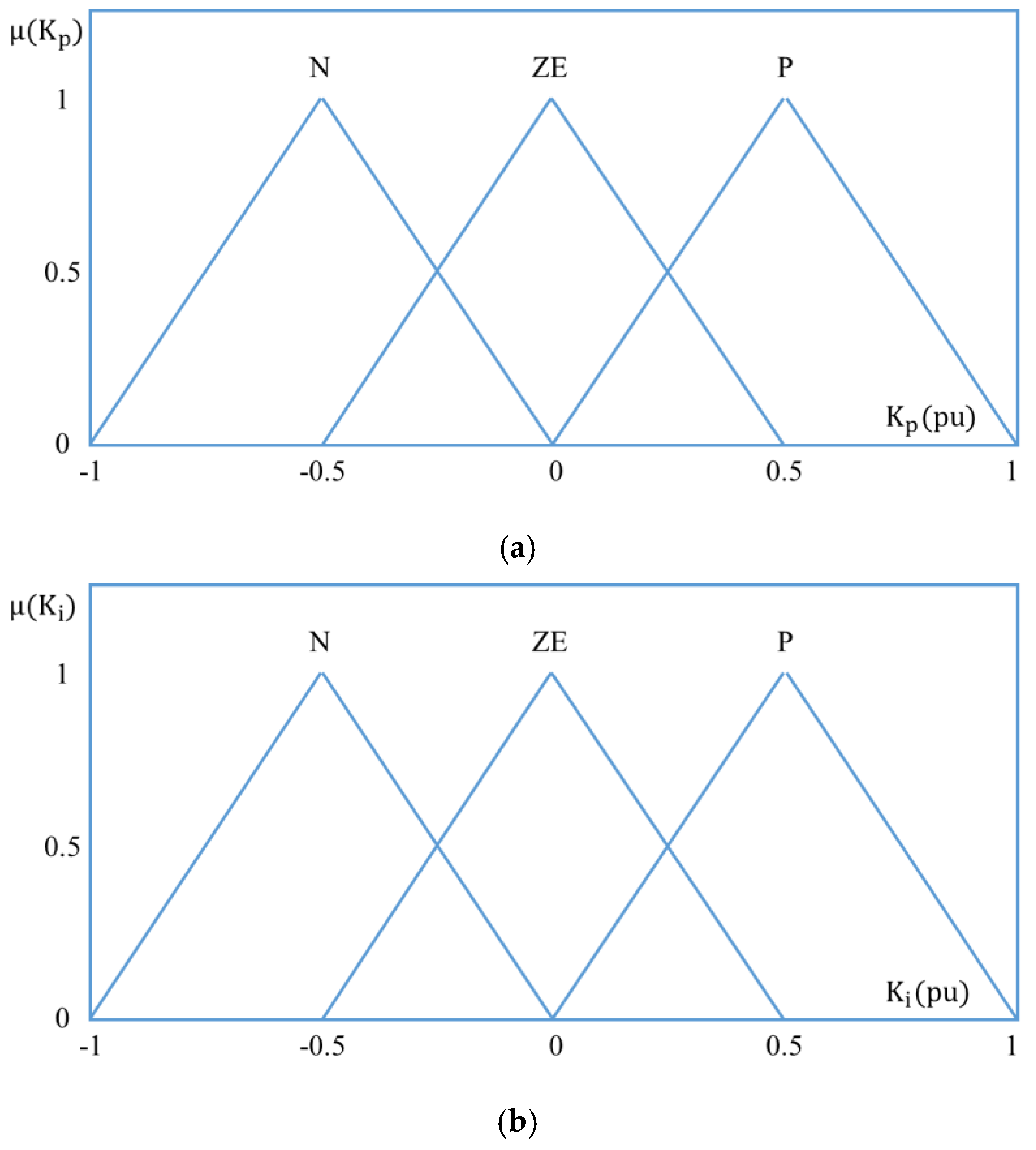
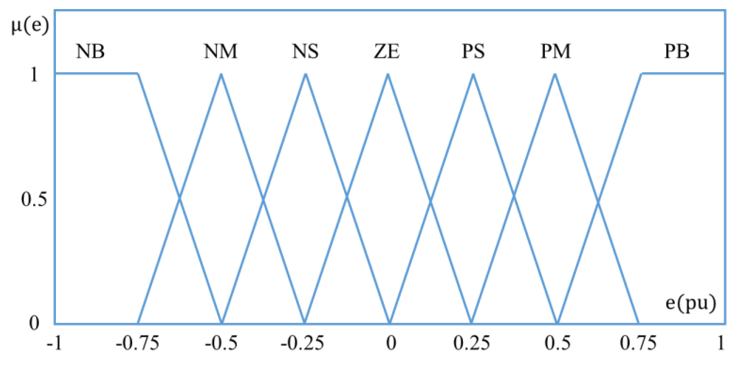
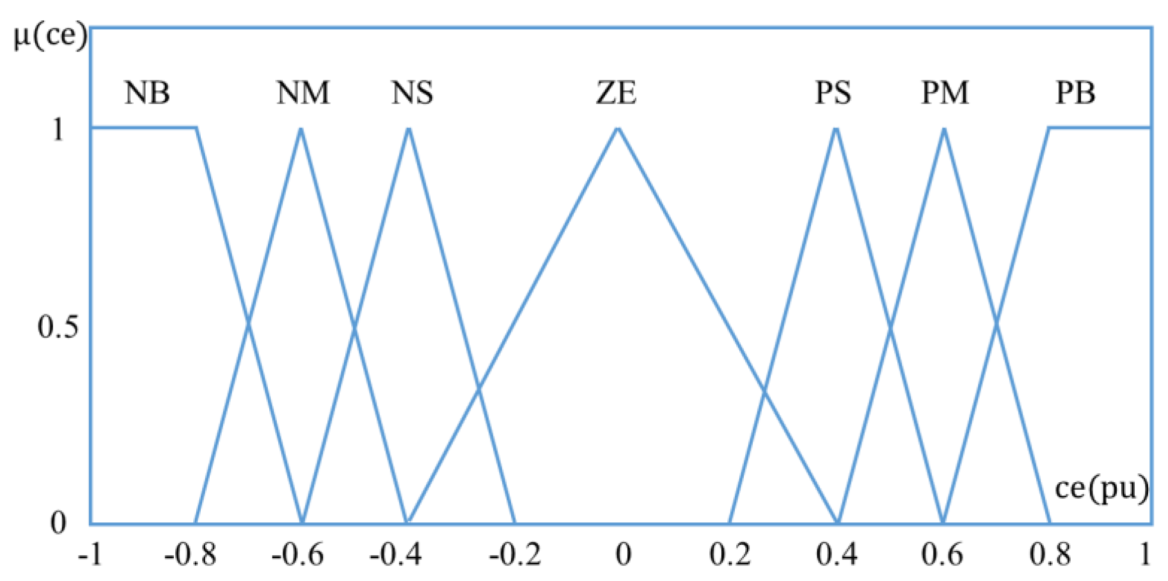
The input of fuzzy control, error and error variation, are divided into seven sections: Negative big (NB), Negative medium (NM), Negative small (NS), zero(ZE), Positive big (PB), Positive medium (PM) and positive small (PS). The output of the fuzzy control is designed to perform three actions: increase (P: positive), hold (ZE: zero) and decrease (N: negative).
Table 4 and Table 5 show the rule base for proportional gain ( K p ) and integral gain ( K i ) designed in the paper, and Figure 8, Figure 9 and Figure 10 show membership function for the input and output of fuzzy control.
E ( k ) = P ( k ) P ( k 1 ) V pv ( k ) V pv ( k 1 )
CE ( k ) = E ( k ) E ( k 1 )
Equations (21)–(24) show the gain of the PI controller adjusted by the fuzzy controller. Outputs Δ K p and Δ K i of the fuzzy controller are calculated using the center of gravity (COG) [27,50]:
K p ( k ) = K p ( k 1 ) + Δ K p
K i ( k ) = K i ( k 1 ) + Δ K i
Δ K p = j = 1 n μ ( K p ) j · ( K p ) j j = 1 n μ ( K p ) j
Δ K i = j = 1 n μ ( K i ) j · ( K i ) j j = 1 n μ ( K i ) j
Figure 11 shows an example of the input error (0.7) and changing error (0.3) of fuzzy control. When the error and error change values are calculated, the membership strength is calculated from the membership functions shown in Figure 8 and Figure 9. In the membership function for error 0.7, the membership strength is 0.8 for PM and 0.2 for PB. For changing error 0.3, the strength of membership is calculated for the membership function, which is 0.5 for ZE and 0.25 for PS. Four output values are calculated through the AND operation of Equation (17) and the rule base of K p in Table 4, and 0.413 can be obtained by calculating the final values through Equation (23).
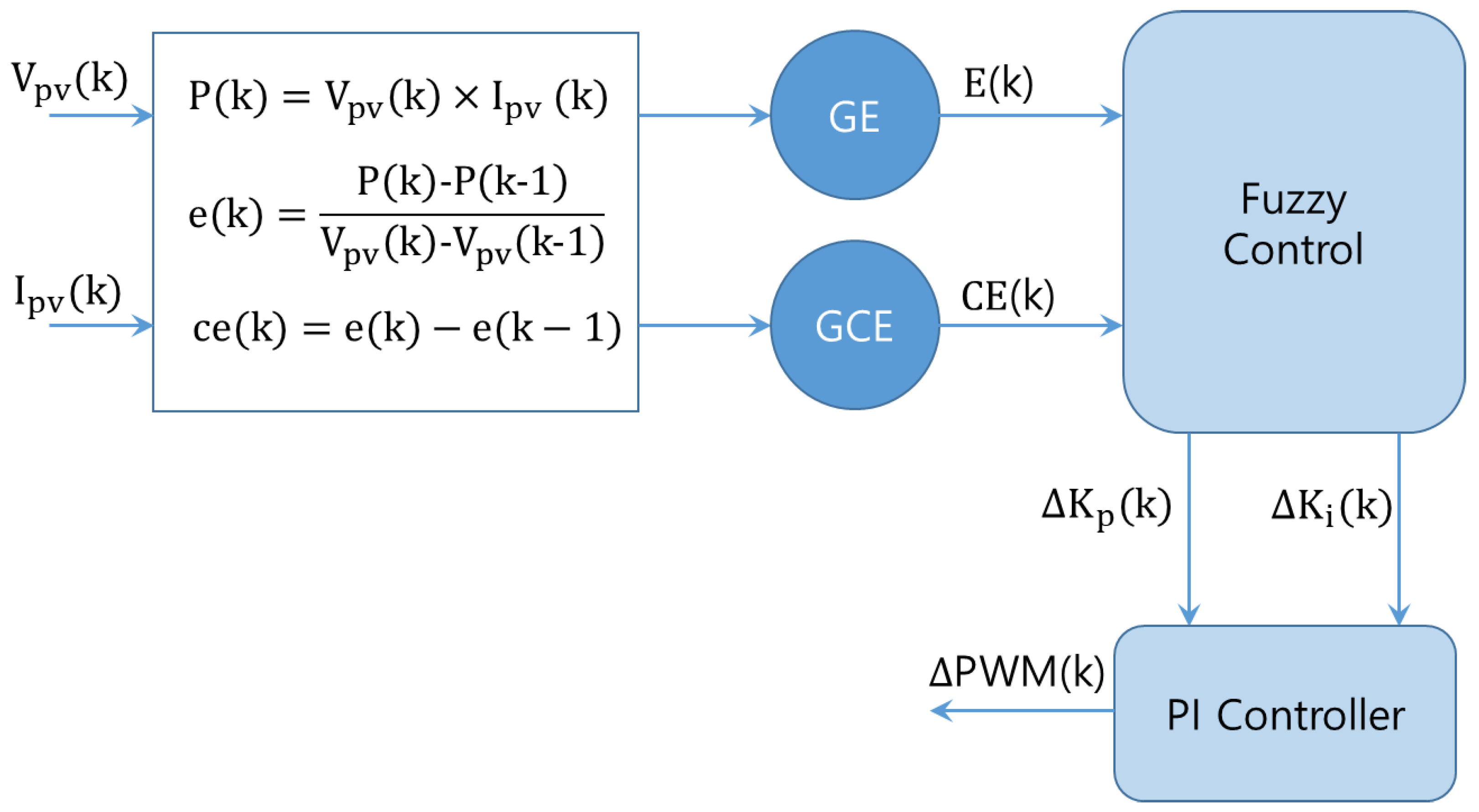
Figure 12 shows the structure of the VGPI controller for MPPT control of the PV system. The inputs are the voltage ( V pv ) and current ( I pv ) of the PV system, and the output is the change value of the PI controller gain value ( Δ K p , Δ K i ) through the fuzzy controller. The PI controller outputs the PWM (Pulse Width Modulation) signal for MPPT control using the adjusted gains by fuzzy control, and this signal controls the DC-DC converter.

4. Experiment Result

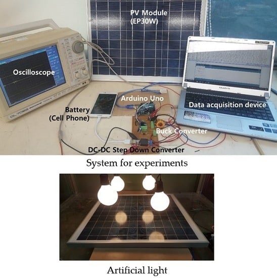
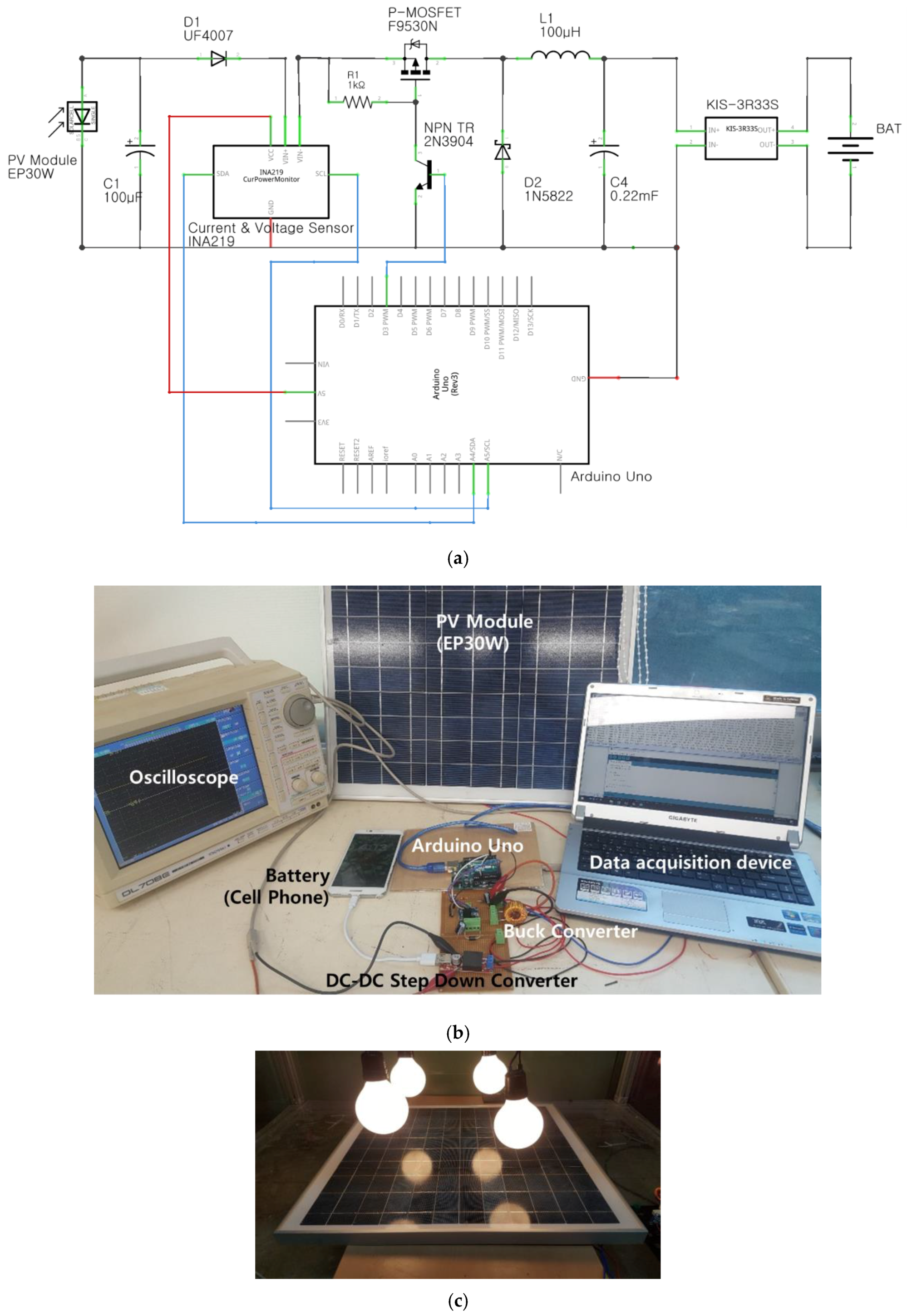
The control performance of MPPT is verified by the speed at which maximum power is tracked and the magnitude of the error in steady state using voltage, current and power output from the PV module. In order to verify MPPT’s performance in the paper, the experimental device was constructed with a PV module, a Buck converter, a DC-DC step down converter and a battery.
Experiments in solar power use solar simulators or use artificial light sources to construct a constant experimental environment. In the paper, a constant experimental environment was constructed using artificial lighting. Artificial light sources in the experimental environment can be used to maintain or change the test conditions. In addition, the same environmental conditions can be configured for different methods, so that the performance of the proposed method and the conventional method can be compared. The proposed method and conventional method compare the speed at which the maximum power point is tracked and the error at steady state. Since the environment is constructed using the same artificial light source, comparisons of output power, voltage and current can be a valid method for verifying peak power point tracking performance [51,52,53,54].
Figure 13 shows the circuit diagram and control system for the MPPT control performance test of solar power generation. In this paper, MPPT control is controlled by the buck converter, and voltage and current are measured using the INA219 voltage current sensor. Switching of the buck converter was performed using P-channel MOSFET (F9530N) for high-side switching of the buck converter. P-channel MOSFET has a switching state of “on” when a "low" signal is inputted to the gate, so the NPN transistor (2N3904) and pull-up resistor (1 kΩ) are used to control the buck converter.
DC-DC step down converter (KIS-3R33S) was used to maintain constant voltage for changes in the voltage of solar power, and the cell phone battery was charged.
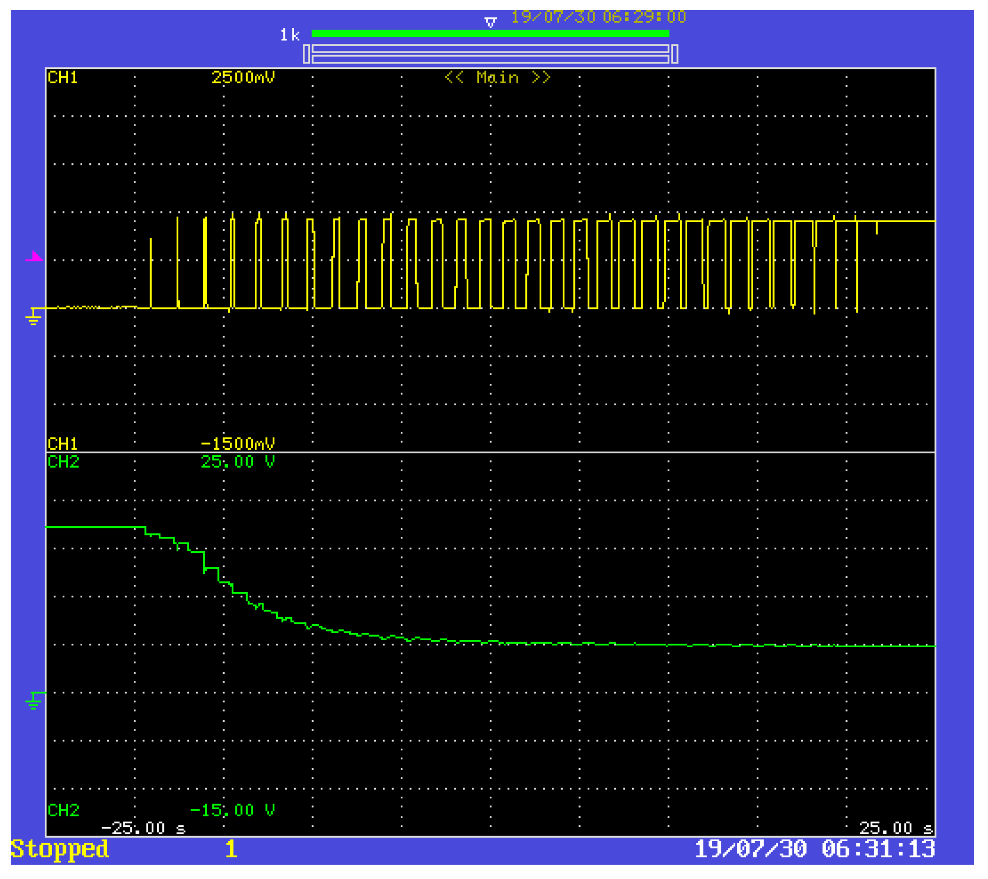
Figure 14 shows the change of output voltage according to PWM signal of Buck Converter. When MPPT control is performed using a buck converter, the voltage gradually decreases from the open-circuit voltage to the load voltage according to the PWM signal. In Figure 14, CH1 represents the PWM signal output from the controller, and CH2 denotes the voltage change of the PV module. The switching frequency of the controller used is 3.9 [kHz].
Figure 15, Figure 16 and Figure 17 show the response characteristics of the VGPI, PI, and P&O methods under constant solar irradiation conditions.
The PI controller used for comparison with VGPI uses 0.035 for proportional gain ( K p ) and 0.005 for integral gain ( K i ). Arduino’s PWM ranges from 0 to 255, with 0 representing 0% and 255 representing 100% duty ratio. The P&O controller adjusts the PWM to a fixed size 3 to regulate the voltage at a constant rate.
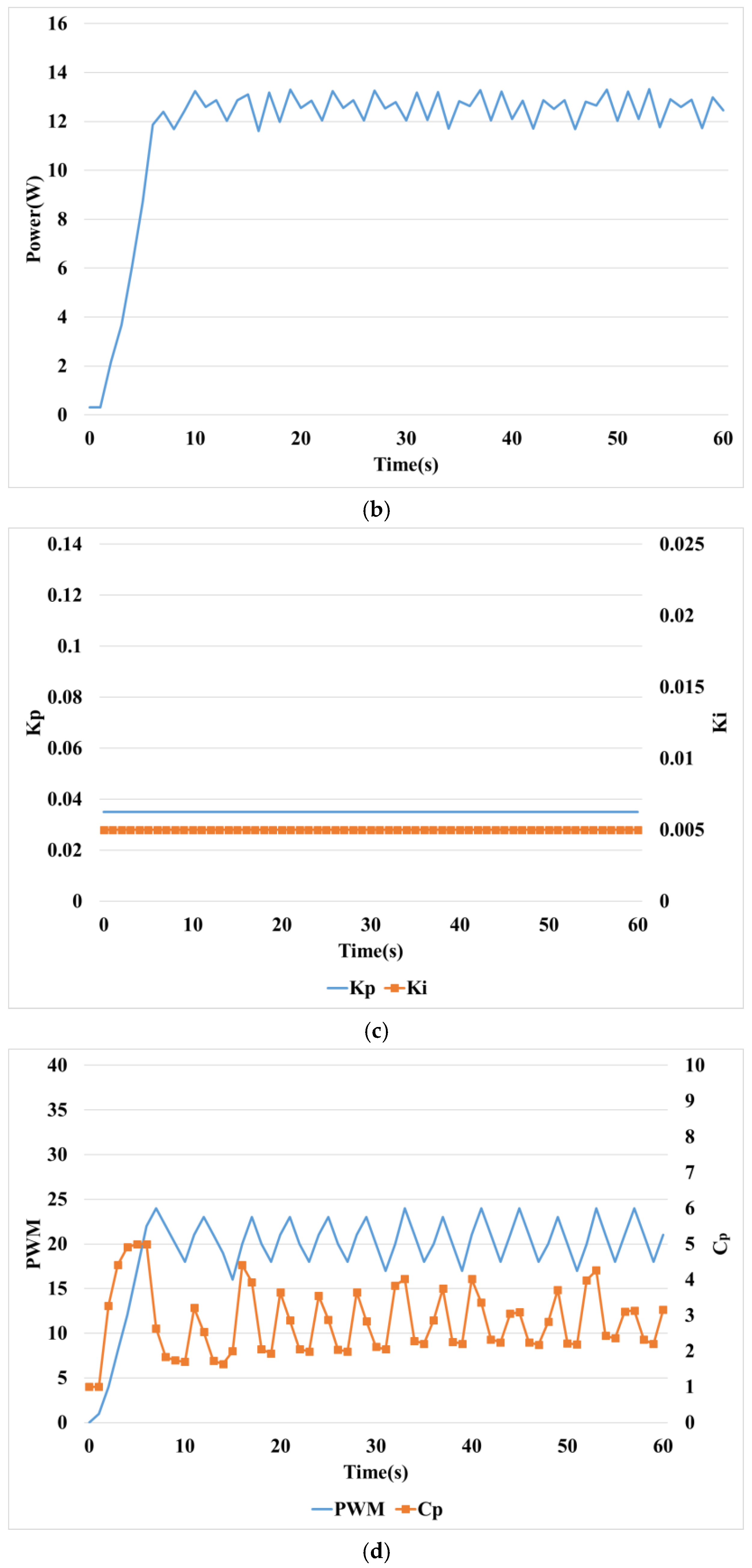
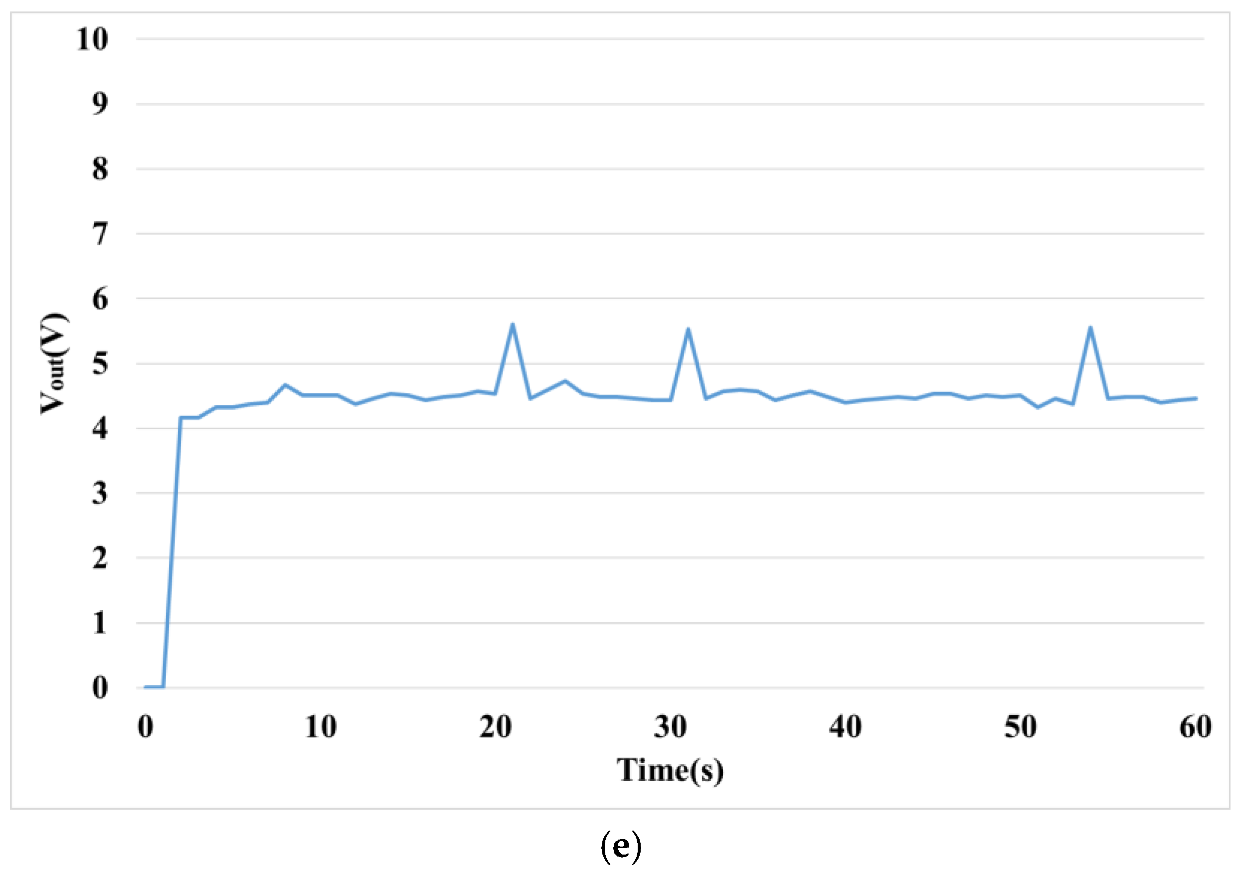
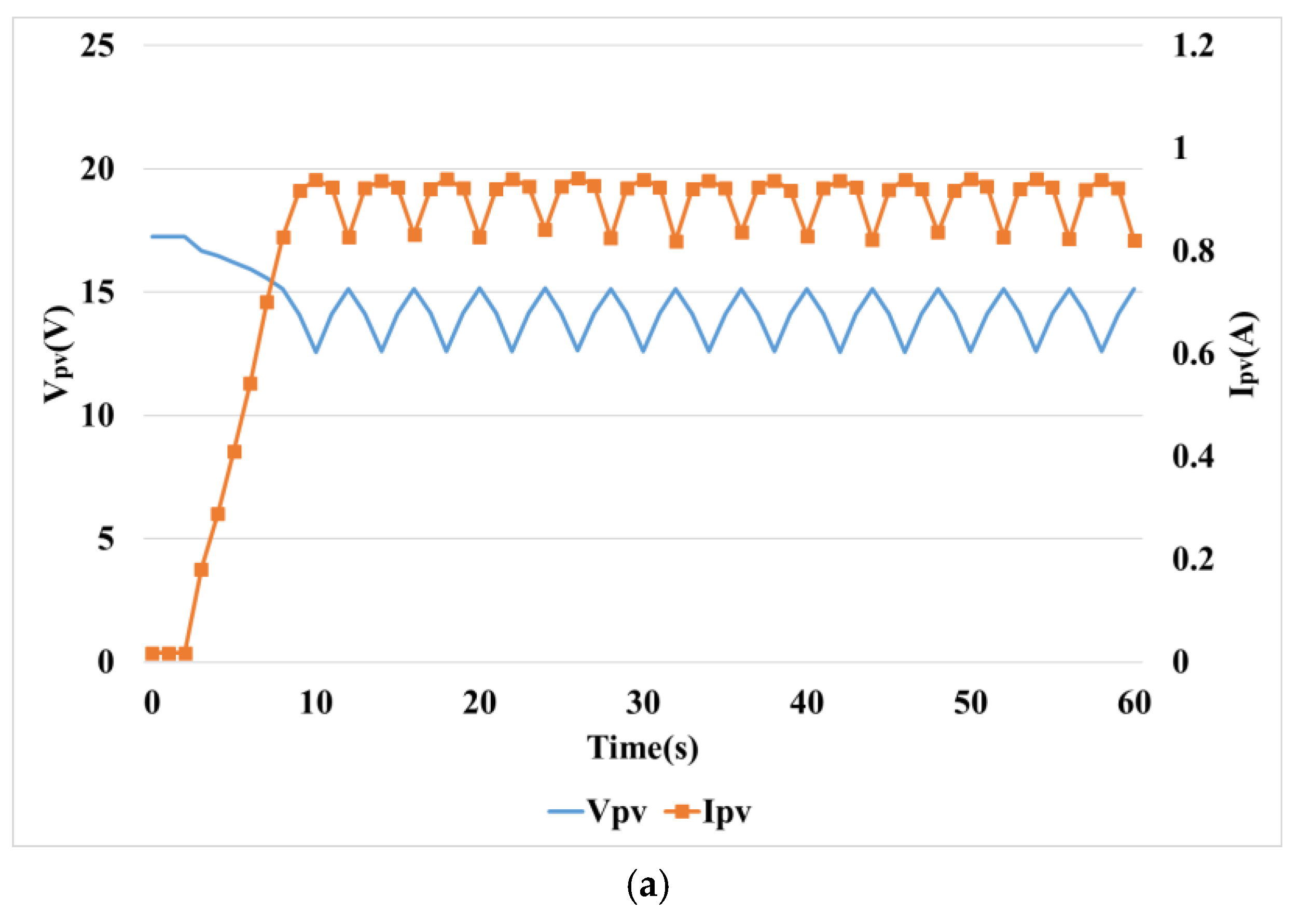
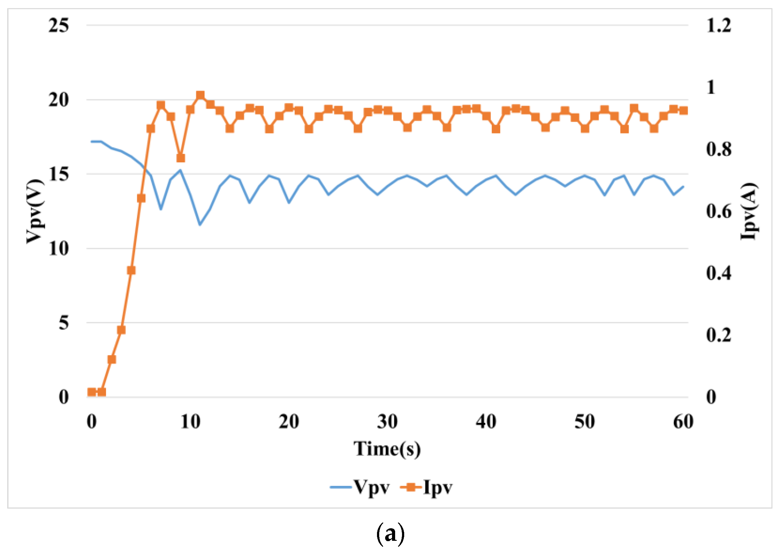
In Figure 15, Figure 15a shows the voltage and current, 
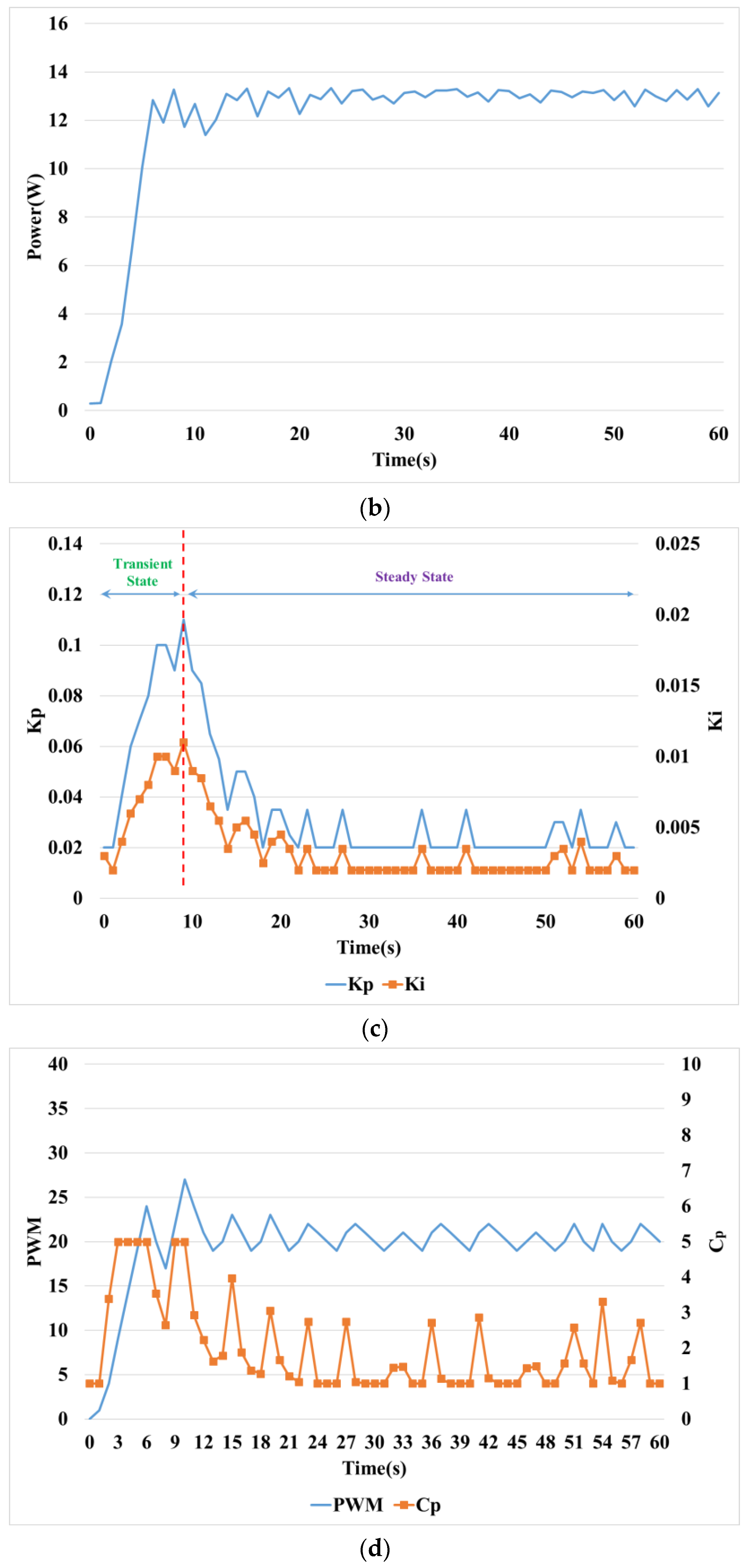
Figure 15b presents the output power, Figure 15c illustrates the gain of the PI controller controlled by fuzzy control, Figure 15d shows the control value ( C p ) and PWM signal for switching control of the DC-DC converter and Figure 15e is output voltage controlled by step down converter. The gain of the PI controller in (C) is increased for fast tracking in transient state, and the gain value is decreased for improving accuracy and stability in steady state. The control value ( C p ) for tracking the MPP increases as the gain of the PI controller is adjusted according to the operating state and decreases in steady state. As a result, the variation of the PWM signal for switching of the DC-DC converter is reduced, and the power ripple is reduced; thus enabling more accurate MPPT. The output voltage in Figure 15e remains constant even as the voltage of solar power changes.
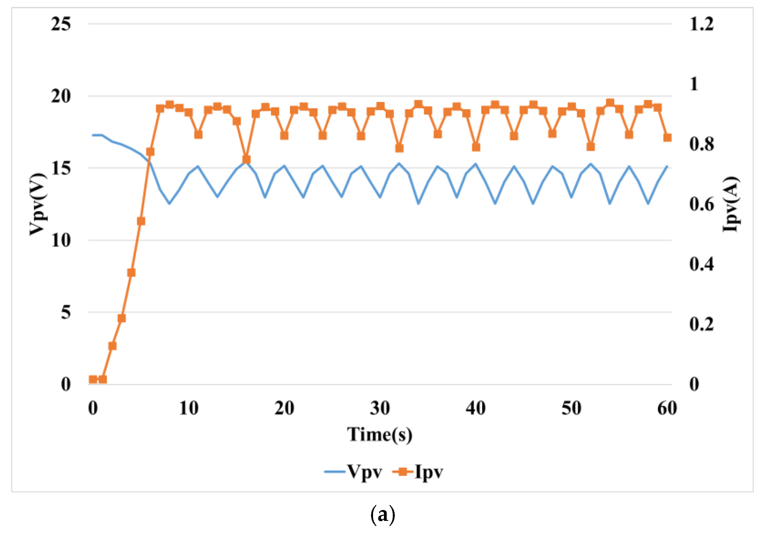
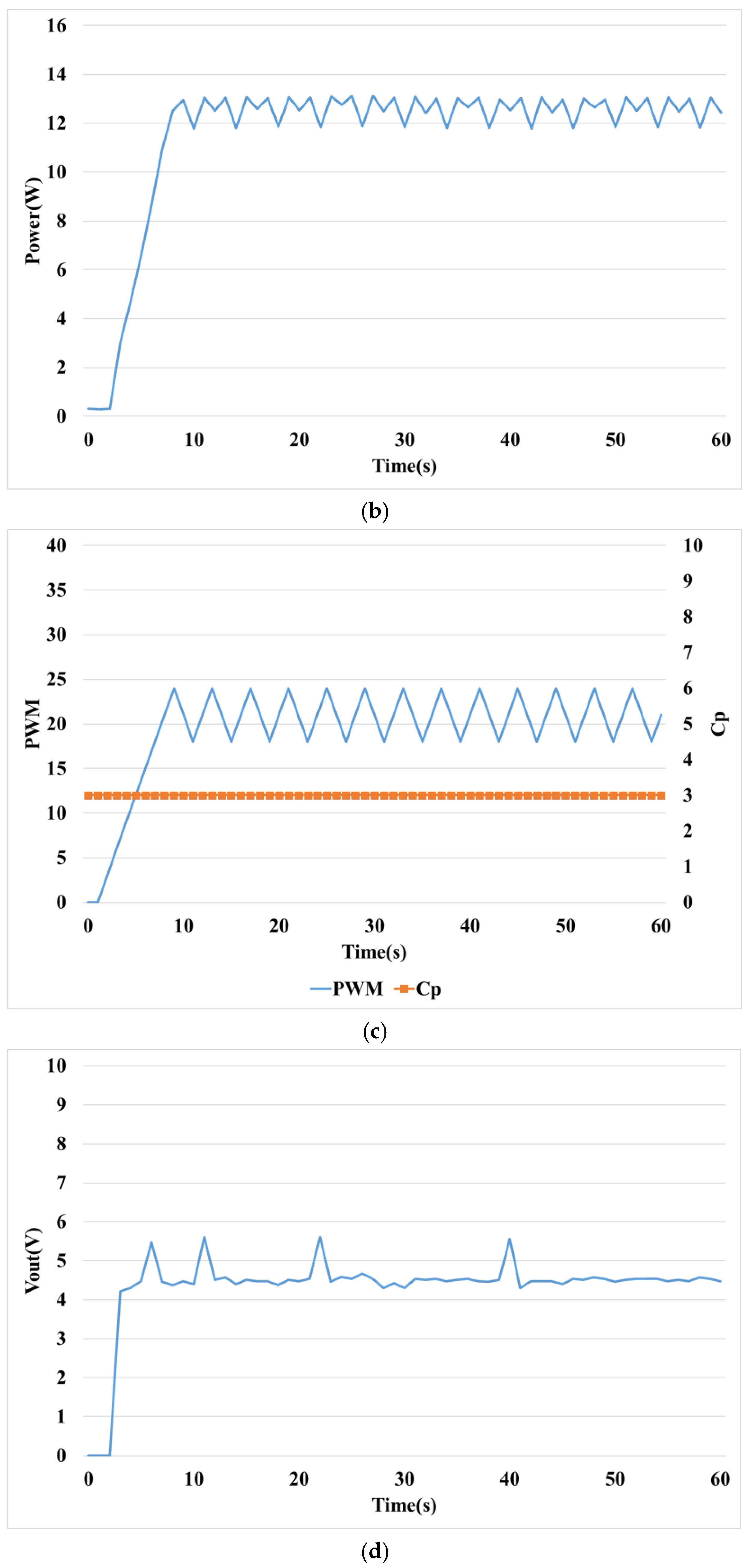
Figure 16 shows the response performance of the MPPT control of photovoltaic power generation using the PI controller. In particular, Figure 16c shows the fixed gain of the PI controller. Although the PWM signal and the control value ( C p ) of Figure 16d are controlled according to operating state by PI control, the ripple of the output power increases because it is larger than the value of Figure 15d.
Figure 17 shows the response characteristics of the most commonly used P&O method for MPPT control. In particular, Figure 17a shows the voltage and current, Figure 17b presents the output power, and Figure 17c shows the PWM signal and control value ( C p ). Since the P&O method uses the fixed control value ( C p ) in both transient state and steady state, voltage in Figure 17a, power in Figure 17b, and PWM signal in Figure 17c have a constant ripple magnitude.
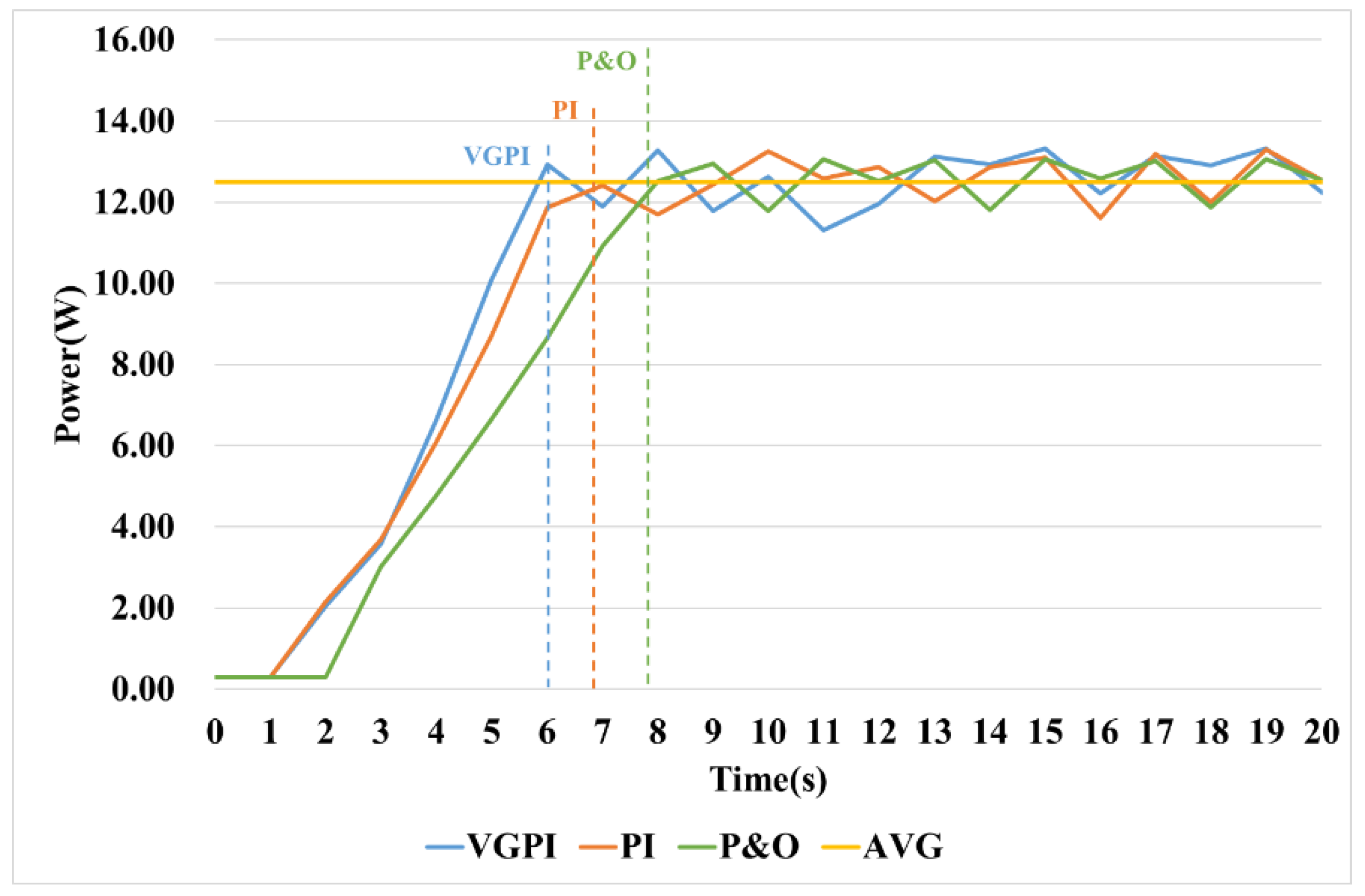
Figure 18 and Table 6 show a comparison of the power response characteristics in transient states of the VGPI, PI, and P&O methods in Figure 15, Figure 16 and Figure 17. The time to trace the maximum power point in transient state was measured as the time to reach the average power (12.5 [W]) of steady state, the results are shown in Table 6. As the results in Table 6 show, the VGPI controller has the most tracking speed with a high gain value in transient.
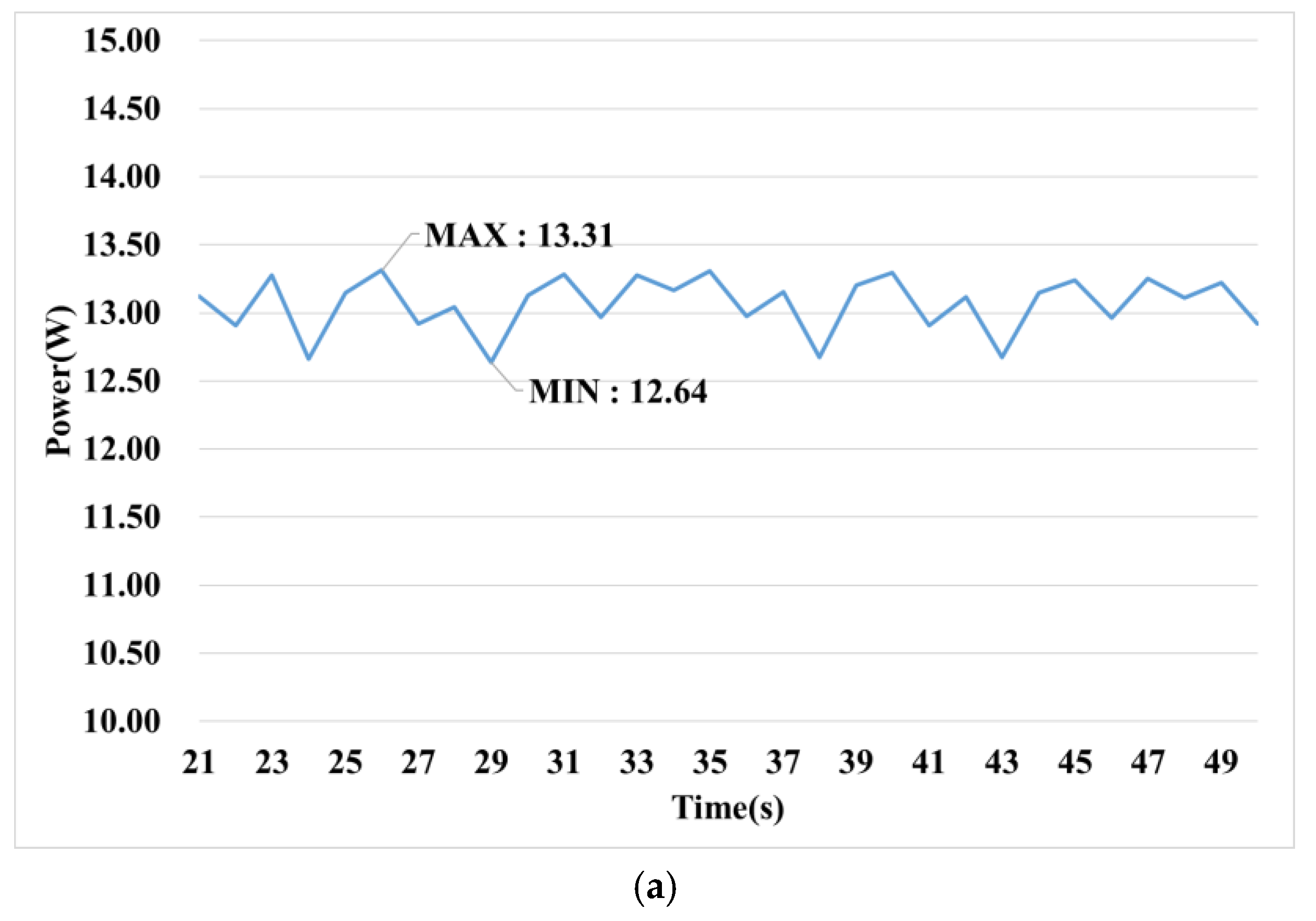
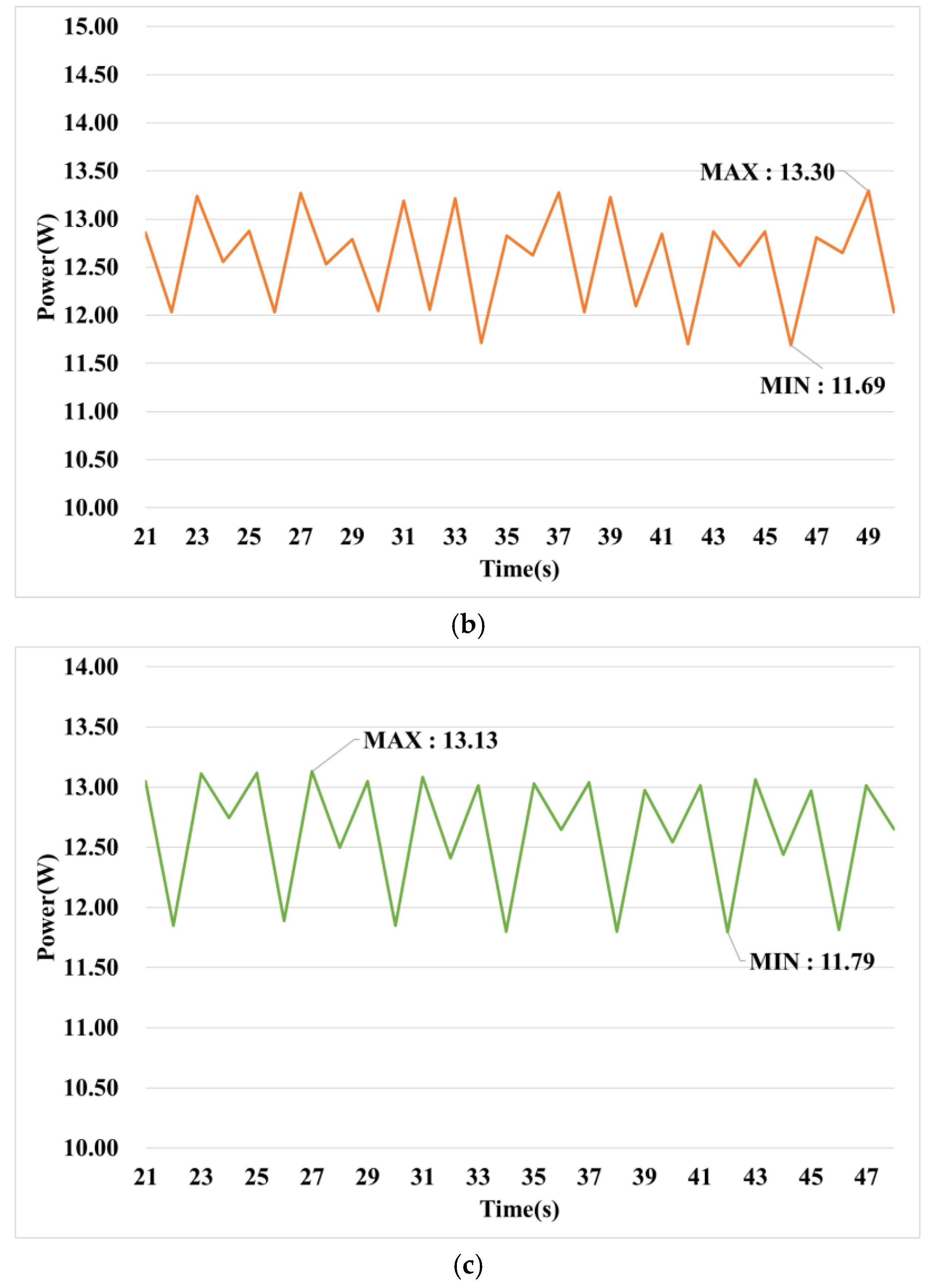
Figure 19 and Table 7 represent the magnified picture and characteristics of the steady-state portion of Figure 15, Figure 16 and Figure 17. The VGPI controller had the lowest error because it had lower gain values in a steady state, and the ripple was about 50% lower than the P&O method. Since the PI controller used a high gain value for fast tracking speed in transient conditions, steady-state error was rather higher than the P&O method.
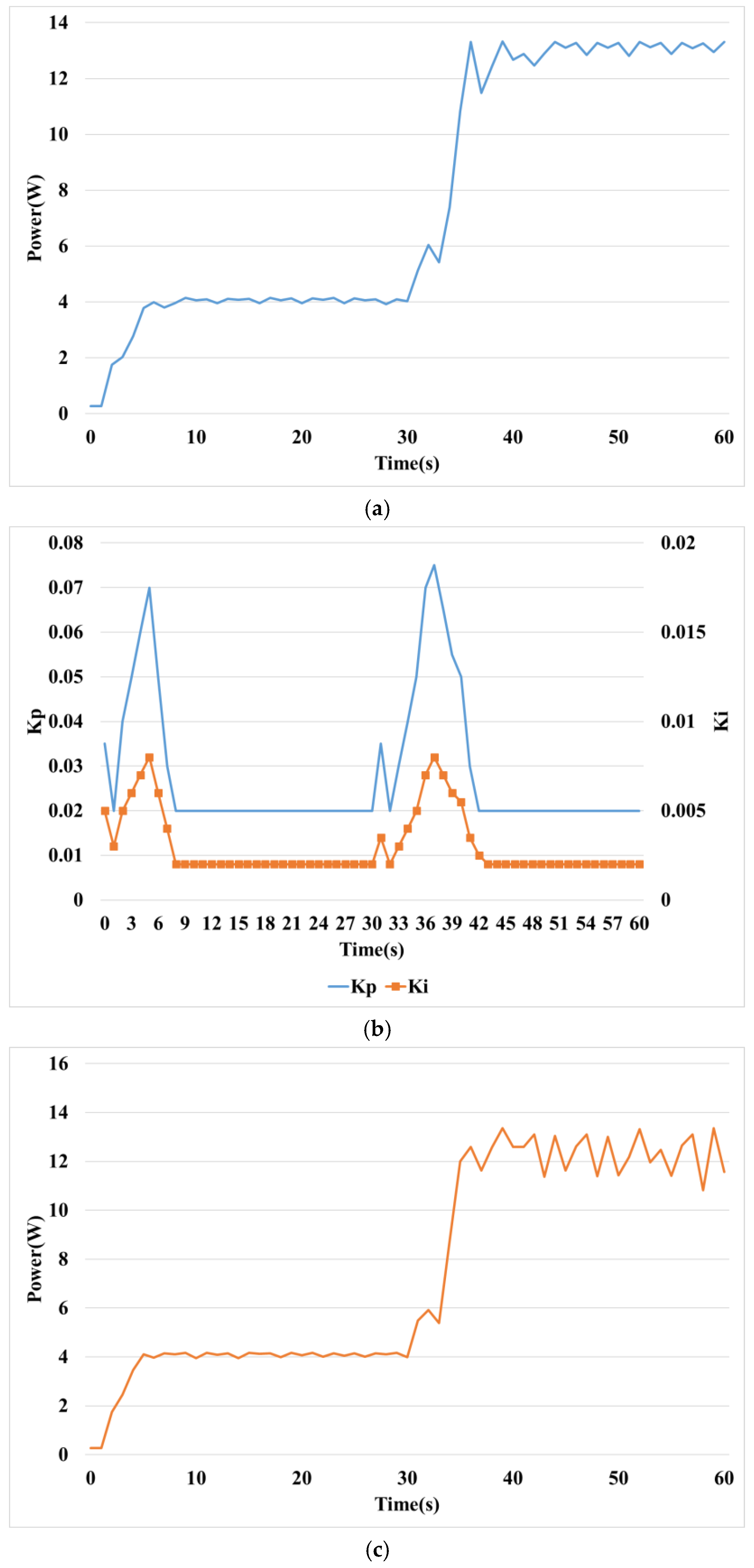
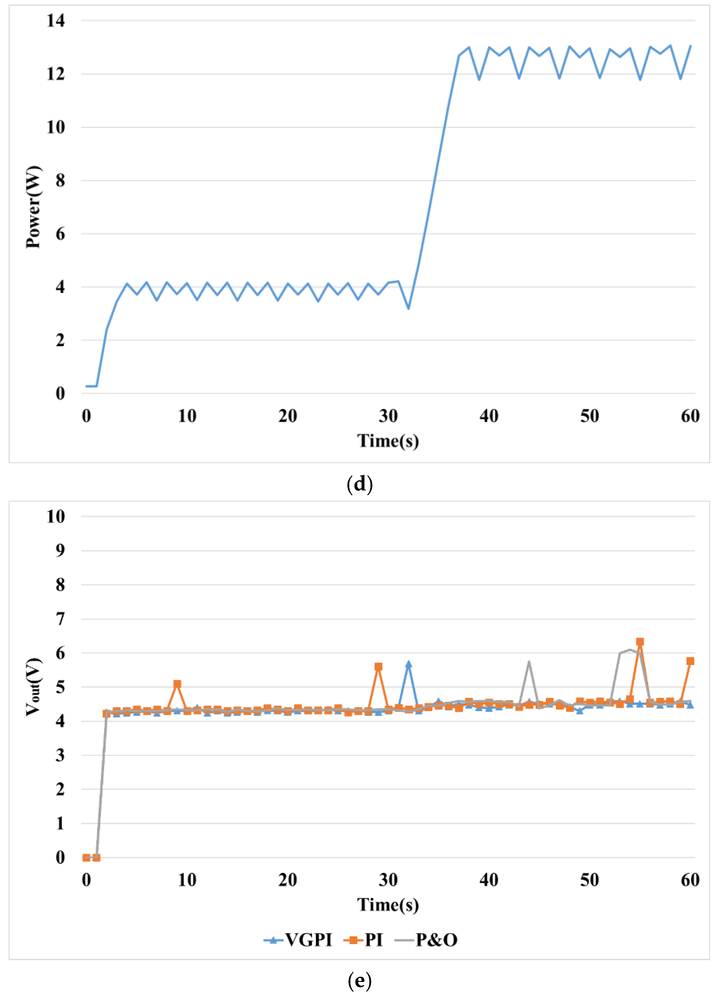
Figure 20 and Table 8 show MPPT control characteristics for changing conditions of solar radiation. Figure 20a represents the output of the VGPI, and Figure 20b represents the change in the gain value of the VGPI controller. The gain value of the VGPI controller represents a characteristic that is increasing in a transient state and is decreasing in steady state. Table 8 shows comparison of steady-state error for conditions with different solar irradiance. VGPI controllers show low steady-state error across all sections. Figure 20d represents the output voltage of the VGPI, PI, and P&O methods, with constant voltage output for the changing conditions of the solar radiation.

5. Conclusions

This paper proposes a method for tracking the MPP of solar power generation. P&O and IncCond methods, which are commonly used MPPT methods, have limitations in performance improvement because they track a MPP by varying a voltage or a current with a constant magnitude.
In this paper, the VGPI controller is proposed to solve this problem. The characteristics of the VGPI controller presented in the paper are as follows.
  • Based on the PI controller, which is most commonly used in industrial sites.
  • The gain value of the PI controller adjusts according to the operating state using fuzzy control.
  • Design a fuzzy control membership function and rule base in accordance with the basic operation of the PV module.
  • The membership function of the fuzzy control output consists of three types: increase (P: Positive), hold (ZE: zero) and decrease (N: negative).
The gain value of the PI controller is increased for a quick response in transient conditions and reduced to reduce steady-state error in normal conditions. The VGPI proposed in this paper compares the tracking time at transient-state and the error in steady state with conventional MPPT methods for two scenarios (constant and changing conditions of solar radiation).
Under constant or varying conditions, the proportional gain ( K p ) and integral gain ( K i ) of the VGPI controller increased to the maximum value in the transient state and decreased to the minimum value in the steady state by the fuzzy control, and were continuously adjusted.
As a result, the VGPI controller proposed in this paper is about 14% better than the conventional PI and P&O in tracking speed, and the error in steady-state shown respectively 36.5% and 40% lower than PI and P&O. Even in conditions with varying solar radiation, the VGPI controller had excellent MPPT performance than other controllers because of continuous gain adjustment. VGPI controllers are able to adjust continuous gain values according to changing environments, and both transient and steady-state response performance was improved.
This method is expected to be applicable to various variable systems, as well as MPPT for solar power. Fuzzy control used in this paper requires continuous calculation according to changing environmental conditions. In addition, the calculation of fuzzy control depends on the membership function and rule base, and the calculation amount can be greatly increased according to the environmental change conditions. This phenomenon degrades the MPPT performance.

Author Contributions

Conceptualization, J.-C.K. and J.-S.K.; Data curation, J.-C.K. and J.-S.K.; Formal analysis, J.-C.K. and J.-H.H.; Funding acquisition, J.-H.H.; Investigation, J.-H.H.; Methodology, J.-C.K., J.-H.H. and J.-S.K.; Project administration, J.-H.H.; Software, J.-H.H. and J.-S.K.; Visualization, J.-S.K.; Writing—original draft, J.-C.K., J.-H.H. and J.-S.K.; Writing—review & editing, J.-H.H. and J.-S.K.

Funding

This research was supported by Energy Cloud R&D Program through the National Research Foundation of Korea (NRF) funded by the Ministry of Science, ICT (NRF-2019M3F2A1073385).

Conflicts of Interest

The authors declare no conflict of interest.

References

  1. Dincer, F. The analysis on photovoltaic electricity generation status, potential and policies of the leading countries in solar energy. Renew. Sustain. Energy Rev. 2011, 15, 713–720. [Google Scholar] [CrossRef]
  2. Eltawil, M.A.; Zhao, Z. Grid-connected photovoltaic power systems: Technical and potential problems—A review. Renew. Sustain. Energy Rev. 2010, 14, 112–129. [Google Scholar] [CrossRef]
  3. Vergura, S. A Complete and Simplified Datasheet-Based Model of PV Cells in Variable Environmental Conditions for Circuit Simulation. Energies 2016, 9, 326. [Google Scholar] [CrossRef]
  4. Coelho, R.F.; Martins, D.C. An Optimized Maximum Power Point Tracking Method Based on PV Surface Temperature Measurement. Available online: https://www.intechopen.com/books/sustainable-energy-recent-studies/an-optimized-maximum-power-point-tracking-method-based-on-pv-surface-temperature-measurement/ (accessed on 7 August 2019).
  5. Hohm, D.P.; Ropp, M.E. Comparative Study of Maximum Power Point Tracking Algorithms Using an Experimental, Programmable, Maximum Power Point Test Bed. In Proceedings of the IEEE Photovoltaic Specialists Conference, Anchorage, AK, USA, 15–22 September 2000; pp. 1699–1702. [Google Scholar]
  6. Tan, C.W.; Green, T.C.; Hernandez-Aramburo, C.A. Analysis of Perturb and Observe Maximum Power Point Tracker Algorithm for Photovoltaic Applications. In Proceedings of the IEEE 2nd International Power and Energy Conference, Johor Bahru, Malaysia, 1–3 December 2008; pp. 237–242. [Google Scholar]
  7. Boico, F.; Lahman, B. Study of Different Implementation Approaches for a Maximum power Point Tracker. In Proceedings of the IEEE Computers in Power Electronics, Troy, NY, USA, 16–19 July 2006; pp. 15–21. [Google Scholar]
  8. Liu, B.; Duan, S.; Liu, F.; Xu, P. Analysis and Improvement of a Maximum Power Point Tracking Algorithm Based on Incremental Conductance Method for Photovoltaic Array. In Proceedings of the IEEE International Conference on Power Applications, Bangkok, Thailand, 27–30 November 2007; pp. 637–641. [Google Scholar]
  9. Yuvarajan, S.; Shoeb, J. A Fast and Accurate Maximum Power Point Tracker for PV Systems. In Proceedings of the IEEE Applied Power Electronics Conference and Exposition, Austin, TX, USA, 24–28 February 2008; pp. 167–172. [Google Scholar]
  10. Femia, N.; Petrone, G.; Spagnuolo, G.; Vitelli, M. Optimizing Sampling Rate of P&O MPPT Technique. In Proceedings of the IEEE Power Electronics Specialist Conference, Aachen, Germany, 20–25 June 2004; Volume 3, pp. 1945–1949. [Google Scholar]
  11. Pandey, A.; Dasgupta, N.; Mukerjee, A. Design Issues in Implementing MPPT for Improved Tracking and Dynamic Performance. In Proceedings of the IEEE Conference on Industrial Electronics, Paris, France, 6–10 November 2006; pp. 4387–4391. [Google Scholar]
  12. Nevzat, O. Recent developments in maximum power point tracking technologies for photovoltaic systems. Int. J. Photoenergy 2010. [Google Scholar] [CrossRef]
  13. De Brito, M.A.G.; Junior, L.G.; Sampaio, L.P.; Melo, G.A.; Canesin, C.A. Main maximum power point tracking strategies intended for photovoltaics. In Proceedings of the XI Power Electronics Brazilian Conference, Praiamar, Brazil, 11–15 September 2011; pp. 524–530. [Google Scholar]
  14. Kjaer, S.B. Evaluation of the “hill climbing” and the incremental conductance maximum power point trackers for photovoltaic power systems. IEEE Trans. Energy Convers. 2012, 27, 922–929. [Google Scholar] [CrossRef]
  15. Elgendy, M.A.; Zahawi, B.; Atkinson, D.J. Assessment of perturb and observe MPPT algorithm implementation techniques for PV pumping applications. IEEE Trans. Sustain. Energy 2012, 3, 21–33. [Google Scholar] [CrossRef]
  16. Abdelsalam, A.; Ahmed, S.; Massoud, A.; Enjeti, P. High performance adaptive perturb and observe MPPT technique for photovoltaic-based microgrids. IEEE Trans. Power Electron. 2011, 26, 1010–1021. [Google Scholar] [CrossRef]
  17. Piegari, L.; Rizzo, R. Adaptive perturb and observe algorithm for photovoltaic maximum power point tracking. IET Renew. Power Gen. 2010, 4, 317–328. [Google Scholar] [CrossRef]
  18. Wasynczuk, O. Dynamic behavior of a class of photovoltaic power systems. IEEE Trans. Power Appl. Syst. 1983, 9, 3031–3037. [Google Scholar] [CrossRef]
  19. Sera, D.; Teodorescu, R.; Hantschel, J.; Knoll, M. Optimized maximum power point tracker for fast-changing environmental conditions. IEEE Trans. Ind. Electron. 2008, 55, 2629–2637. [Google Scholar] [CrossRef]
  20. Pandey, A.; Dasgupta, N.; Mukerjee, A.K. High-performance algorithms for drift avoidance and fast tracking in solar MPPT system. IEEE Trans. Energy Convers. 2008, 23, 681–689. [Google Scholar] [CrossRef]
  21. Fortunato, M.; Giustiniani, A.; Petrone, G.; Spagnuolo, G.; Vitelli, M. Maximum power point tracking in a one-cycle-controlled single-stage photovoltaic inverter. IEEE Trans. Ind. Electron. 2008, 55, 2684–2693. [Google Scholar] [CrossRef]
  22. Patel, H.; Agarwal, V. MPPT scheme for a PV-fed single-phase single-stage grid-connected inverter operating in CCM with only one current sensor. IEEE Trans. Energy Convers. 2009, 24, 256–263. [Google Scholar] [CrossRef]
  23. Ropp, M.E.; Gonzalez, S. Development of a MATLAB/Simulink model of a single-phase grid-connected photovoltaic system. IEEE Trans. Energy Convers. 2009, 24, 195–202. [Google Scholar] [CrossRef]
  24. Koutroulis, E.; Kalaitzakis, K.; Voulgaris, N.C. Development of a microcontroller-based, photovoltaic maximum power point tracking control system. IEEE Trans. Power Electron. 2001, 16, 46–54. [Google Scholar] [CrossRef]
  25. Veerachary, M.; Senjyu, T.; Uezato, K. Neural-network-based maximum-power-point tracking of coupled-inductor interleavedboost-converter-supplied PV system using fuzzy controller. Ind. Electron. IEEE Trans. 2003, 50, 749–758. [Google Scholar] [CrossRef]
  26. Mirbagheri, S.Z.; Aldeen, M.; Saha, S. A Comparative Study of MPPT Algorithms for Sandalone PV Systems under RCIC. In Proceedings of the 2015 IEEE PES Asia-Pacific Power and Energy Engineering Conference (APPEEC), Brisbane, Australia, 15–18 November 2015; pp. 1–5. [Google Scholar]
  27. Ko, J.S.; Huh, J.H.; Kim, J.C. Improvement of Temperature Control Performance of Thermoelectric Dehumidifier Used Industry 4.0 by the SF-PI Controller. Processes 2019, 7, 98. [Google Scholar] [CrossRef]
  28. Ko, J.S.; Huh, J.H.; Kim, J.C. Improvement of Energy Efficiency and Control Performance of Cooling System Fan Applied to Industry 4.0 Data Center. Electronics 2019, 8, 582. [Google Scholar] [CrossRef]
  29. Ang, K.H.; Chong, G.; Li, Y. PID control system analysis, design, and technology. IEEE Trans. Control Syst. Technol. 2005, 13, 559–576. [Google Scholar]
  30. Li, Y.; Ang, K.H.; Chong, G.C.Y. Patents, software, and hardware for PID control: An overview and analysis of the current art. IEEE Control Syst. 2006, 26, 42–54. [Google Scholar]
  31. Qin, Y.; Sun, L.; Hua, Q.; Liu, P. A Fuzzy Adaptive PID Controller Design for Fuel Cell Power Plant. Sustainability 2018, 10, 2438. [Google Scholar] [CrossRef]
  32. Sun, L.; Li, D.; Lee, K.Y. Optimal disturbance rejection for PI controller with constraints on relative delay margin. ISA Trans. 2016, 63, 103–111. [Google Scholar] [CrossRef] [PubMed]
  33. Wang, J.-S.; Yang, G.H. Data-Driven Approach to Accommodating Multiple Simultaneous Sensor Faults in Variable-Gain PID Systems. IEEE Trans. Ind. Electron. 2019, 66, 3117–3126. [Google Scholar] [CrossRef]
  34. Pal, A.K.; Mudi, R.K. Self-Tuning Fuzzy PI Controller and its Application to HVAC System. Int. J. Comput. Cogn. (IJCC) 2008, 1, 25–30. [Google Scholar]
  35. Kassem, A.M. Fuzzy-logic Based Self-tuning PI Controller for High-Performance Vector Controlled Induction Motor Fed by PV-Generator. Wseas Trans. Syst. 2013, 12, 22–31. [Google Scholar]
  36. Wahyunggoro, O.; Saad, N. Development of Fuzzy-logic-based Self Tuning PI Controller for Servomotor. In Advanced Strategies for Robot Manipulators; INTECH: Shanghai, China, 2010; pp. 311–328. [Google Scholar]
  37. Anantwar, H.; Lakshmikantha, B.R.; Sundar, S. Fuzzy self tuning PI controller based inverter control for voltage regulation in off-grid hybrid power system. In Proceedings of the International Conference on Power Engineering, Computing and CONtrol (PECCON), Chennai, India, 2–4 March 2017; Volume 117, pp. 409–416. [Google Scholar]
  38. Mudi, R.K.; Pal, N.R. A self-tuning fuzzy PI controller. Fuzzy Sets Syst. 2000, 115, 327–338. [Google Scholar] [CrossRef]
  39. Ibarra, L.; Webb, C. Advantages of Fuzzy Control While Dealing with Complex/Unknown Model Dynamics: A Quadcopter Example. Available online: https://www.intechopen.com/books/new-applications-of-artificial-intelligence/advantages-of-fuzzy-control-while-dealing-with-complex-unknown-model-dynamics-a-quadcopter-example/ (accessed on 7 August 2019).
  40. Walker, G.R.; Sernia, P.C. Cascaded dc-dc converter connection of photovoltaic modules. IEEE Trans. Power Electron. 2004, 19, 1130–1139. [Google Scholar] [CrossRef]
  41. Ghasemi, A.; Eilaghi, S.F.; Adib, E. A new non-isolated high step up SEPIC converter for photovoltaic applications. In Proceedings of the 3rd Power Electronics and Drive Systems Technology Conference, Tehran, Iran, 15–16 February 2012; pp. 51–56. [Google Scholar]
  42. Coelho, R.F.; Concer, F.M.; Martins, D.C. A Simplified Analysis of DC-DC Converters Applied as Maximum Power Point Tracker in Photovoltaic Systems. In Proceedings of the IEEE International Symposium on Power Electronics for Distributed Generation Systems, Hefei, China, 16–18 June 2010; pp. 1–14. [Google Scholar]
  43. Taghvaee, M.; Radzi, M.A.M.; Moosavain, S.; Hizam, H.; Marhaban, M.H. A current and future study on non-isolated DC-DC converters for photovoltaic applications. Renew. Sustain. Energy Rev. 2013, 17, 216–227. [Google Scholar] [CrossRef]
  44. Ramki, T.; Tripathy, L.N. Comparison of Different DC-DC Converter for MPPT Application of Photovoltaic System. In Proceedings of the International Conference on Electrical, Electronics, Signals, Communication and Optimization, Visakhapatnam, India, 24–25 January 2015; pp. 1–6. [Google Scholar]
  45. Baharudin, N.H.; Mansur, T.M.N.T.; Hamid, F.A.; Misrun, M.I. Topologies of DC-DC Converter in Solar PV Applications. Indones. J. Electr. Eng. Comput. Sci. 2017, 8, 368–374. [Google Scholar] [CrossRef]
  46. Umashankar, S.; Srikanth, P.; Vijay Kumar, D.; Kothari, D.P. Comparative Study of Maximum Power Point Tracking Algorithms with DC-DC Converters for Solar PV System. Int. J. Electr. Comput. Eng. 2011, 3, 11–20. [Google Scholar]
  47. Mahanta, J.; Sharma, B.; Sarmah, N. A Review of Maximum Power Point Tracking Algorithm for Solar Photovoltaic Applications. J. Electr. Electron. Eng. 2018, 13, 1–13. [Google Scholar]
  48. Vuksic, M.; Kovacevic, T.; Mise, J. Solar Climber: A Problem Solving Approach in Power Electronics and Control Systems Teaching. Available online: https://www.researchgate.net/publication/263470253_Solar_Climber_A_Problem_Solving_Approach_in_Power_Electronics_and_Control_Systems_Teaching/ (accessed on 23 July 2019).
  49. Rao, K.S.; Mishra, R. Comparative study of P, PI and PID controller for speed control of VSI-fed induction motor. Int. J. Eng. Dev. Res. 2014, 2, 2740–2744. [Google Scholar]
  50. Saletic, D.Z.; Velasevic, D.M.; Mastorakis, N.E. Analysis of Basic Defuzzification Techniques. Available online: https://www.researchgate.net/publication/264874571_Analysis_of_Basic_Defuzzification_Techniques/ (accessed on 7 August 2019).
  51. Haque, A. Maximum Power Point Tracking (MPPT) Scheme for Solar Photovoltaic System. Energy Technol. Policy 2014, 1, 115–122. [Google Scholar] [CrossRef]
  52. Na, W.; Chen, P.; Kim, J.H. An Improvement of a Fuzzy Logic-Controlled Maximum Power Point Tracking Algorithm for Photovoltaic Applications. Appl. Sci. 2017, 7, 326. [Google Scholar] [CrossRef]
  53. Li, C.; Chen, Y.; Zhou, D.; Liu, J.; Zeng, J. A High-Performance Adaptive Incremental Conductance MPPT Algorithm for Photovoltaic Systems. Energies 2016, 9, 288. [Google Scholar] [CrossRef]
  54. Piegari, L.; Rizzo, R.; Spina, I.; Tricoil, P. Optimized Adatpvie Perturb and Observe Maximum Power Point Tracking Control for Photovoltaic Generation. Energies 2015, 8, 3418–3436. [Google Scholar] [CrossRef]
Figure 1. Maximum power point tracking (MPPT) control of the photovoltaic (PV) system by DC-DC converter.
Sustainability 11 05891 g001
Figure 2. I-V curve of the PV module.
Sustainability 11 05891 g002
Figure 3. Structure of the buck converter.
Sustainability 11 05891 g003
Figure 4. MPPT range according to the inclination angle.
Sustainability 11 05891 g004
Figure 5. Flowchart of the Perturb & Observe (P&O) MPPT method.
Sustainability 11 05891 g005
Figure 6. Control principle of the IncCond MPPT method.
Sustainability 11 05891 g006
Figure 7. Flow chart of the IncCond method.
Sustainability 11 05891 g007
Figure 8. Member function for error.
Sustainability 11 05891 g008
Figure 9. Member function for changing error (ce).
Sustainability 11 05891 g009
Figure 10. Member function for output. (a) Proportional gain ( K p ); (b) Integral gain ( K i ).
Sustainability 11 05891 g010
Figure 11. K p calculation for error and changing error.
Sustainability 11 05891 g011
Figure 12. Variable gain proportional integral (VGPI) controller for the MPPT control of the PV system.
Sustainability 11 05891 g012
Figure 13. Experimental setup for the MPPT control performance test of the PV system. (a) Circuit diagram for experiments; (b) System for experiments; (c) Artificial light.
Sustainability 11 05891 g013
Figure 14. PWM signal and voltage PV module ( V pv ).
Sustainability 11 05891 g014
Figure 15. Response characteristics of the VGPI MPPT method. (a) Voltage ( V pv ) and Current ( I pv ) of the PV module; (b) Output Power of the PV module; (c) Proportional gain ( K p ) and Integral gain ( K i ) of the PI controller; (d) PWM signal and control value ( C p ) (e) Output Voltage.
Sustainability 11 05891 g015aSustainability 11 05891 g015bSustainability 11 05891 g015c
Figure 16. Response characteristics of the PI MPPT method. (a) Voltage ( V pv ) and Current ( I pv ) of the PV module; (b) Output Power of the PV module; (c) Proportional gain ( K p ) and Integral gain ( K i ) of the PI controller; (d) PWM signal and control value ( C p ); (e) Output Voltage.
Sustainability 11 05891 g016aSustainability 11 05891 g016bSustainability 11 05891 g016c
Figure 17. Response characteristics of the P&O MPPT method. (a) Voltage ( V pv ) and Current ( I pv ) of the PV module; (b) Output Power of the PV module; (c) PWM signal and control value ( C p ); (d) Output Voltage.
Sustainability 11 05891 g017aSustainability 11 05891 g017b
Figure 18. Comparison of response characteristics in transient state.
Sustainability 11 05891 g018
Figure 19. Comparison of response characteristics in steady state. (a) VGPI MPPT method; (b) PI MPPT method; (c) P&O MPPT method.
Sustainability 11 05891 g019aSustainability 11 05891 g019b
Figure 20. Comparison of MPPT control response characteristics for solar radiation variation. (a) Power of VGPI MPPT method; (b) Gain of VGPI method; (c) Power of PI MPPT method; (d) P&O MPPT method; (e) Output Voltage.
Sustainability 11 05891 g020aSustainability 11 05891 g020b
Table 1. Maximum and minimum inclination angles.
Minimum Inclination AngleMaximum Inclination Angle
θ | D = 0 = 0 θ | D = 1 = atan ( 1 R )
Table 2. Operating state of the P&O method according to the voltage and power states.
CasePerturbation
[ Δ V pv = V pv ( k ) V pv ( k 1 ) ]
Change in Power
[ Δ P = P ( k ) P ( k 1 ) ]
Next Perturbation
[ Δ V ref ( k ) ]
1PositivePositivePositive
2PositiveNegativeNegative
3NegativePositiveNegative
4NegativeNegativePositive
Table 3. Influence of the proportional integral (PI) controller gain value on the system.
ParameterRise TimeOvershootSettling TimeSteady-State Error
K p IncreaseDecreaseIncreaseSmall ChangeDecrease
K i IncreaseDecreaseIncreaseIncreaseDecrease Significantly
Table 4. Rule base to adjust gain K p .
eNBNMNSZEPSPMPB
ce
NBPPZEZEZEPP
NMPZEZENZEZEP
NSPPNNNPP
ZEPZENNNZEP
PSPPNNNPP
PMPZEZENZEZEP
PBPPZEZEZEPP
Table 5. Rule base to adjust gain K i .
eNBNMNSZEPSPMPB
ce
NBPPZEZEZEPP
NMPPZENZEPP
NSPPNNNPP
ZEPZENNNZEP
PSPPNNNPP
PMPPZENZEPP
PBPPZEZEZEPP
Table 6. Comparison of rising time in Figure 18.
VGPIPIP&O
Rising Time(sec)5.94 (73.7%)7.13 (88.4%)8.06 (100%)
Table 7. Comparison of peak to peak in Figure 5.
VGPIPIP&O
Min(W)12.6411.6911.79
Max(W)13.3113.3013.13
Peak to peak(W)0.67(50.3%)1.60(119.8%)1.13(100%)
Table 8. Comparison of steady-state error to solar radiation variation.
VGPIPIP&O
11–30[sec]MIN [W]3.953.963.46
MAX [W]4.154.164.17
Peak to Peak [W]0.20 (29.6%)0.20 (29.6%)0.71 (100%)
41–60[sec]MIN [W]12.4710.8211.78
MAX [W]13.3113.3513.07
Peak to Peak [W]0.84 (65.0%)2.53 (195.9%)1.29 (100%)

