1. Introduction
The mining-downward process in steeply inclined thick coal seams inevitably causes repeated damage to the surrounding rock and surface collapse, degrading the original fragile ecological environment. Chain dynamic disasters are more likely to be triggered in high-stress areas with an increase in the mining depth. Horizontal sublevel caving and caving technology are applied at the Wudong coal mine, leading to roof cracks above the work face that can easily penetrate through the surface by the action of multiple stress fields, forming water and gas channels connected with the goaf and threatening mining safety. When the mining depth reaches 400 m, dynamic disasters and accidents frequently occur, damaging the mining systems and equipment, thereby heavily affecting the safety, efficiency, and sustainability of mining. It is critical to investigate the cut-and-fill mining technologies used in steeply inclined thick coal seams to improve the mining environment, both underneath and above the mining area, and to ensure safe and green mining.
During production, coal mines can discharge large quantities of up to 150 to 200 million tons of gangue and other wastes. In addition, the discharge of massive volumes of construction waste from urban development activities and all kinds of other projects also jeopardize the environment. China has made constructing a resource-efficient and environment-friendly society a fundamental national policy in the
Suggestions of the CPC Central Committee on the Thirteenth Five-Year Plan for National Economic and Social Development. Academician Minggao Qian and others took the lead in proposing the concept of “green coal mining technology” and other related technologies [
1]. Heping Xie proposed a scientific concept for the exploitation of natural resources in a safe, efficient, green, economical, and socially harmonious way under the premise of harmonizing geological work with the eco-environment [
2,
3]. In recent years, governments at all levels have established stricter requirements on environmental protection. Since June 2017, taxes and fees of 5 yuan/ton have been levied on coal gangue emissions. The 19th National Congress also put the importance of environmental protection at an unprecedented level.
Cut-and-fill mining methods are classified from the viewpoint of locations, dynamics, materials, and filling volume [
4,
5,
6]. After several advances, in recent years, filling technologies in the mines located in China have mostly targeted filling and subsidence restraint the modeling experiment on the movement and failure of overlaying strata being filled with gangue. Jia-chen Wang et al. [
7] determined that cut-and-fill mining can limit the deformation, subsidence, and caving of the roof strata directly above the goaf. Hong-sheng Tu et al. [
8] extracted the equation according to collapse characteristics of the roofs collapse at steeply inclined coal seams, and analyzed the factors affecting the width of the backfill. Qingxiang Huang et al. [
9] reported that the size and effect of filling depend on the strength of the filling material and defined the scope of strength of the filling material in early and late stages of cut-and-fill mining. Based on the discussion based on Gadde theory and numerical calculations, Kostecki et al. concluded that the loading capacity of floor strata can be increased by approximately 10–40% when filled with viscous material to approximately 25–75% of the mining height. Furthermore, they reported that when the shear resistance, tensile strength, and rigidity of the filling are reduced, the enhancement in the strength of a coal pillar is not determined by the filling material [
10]. Jixiong Zhang and other scholars from the China University of Mining and Technology conducted systematic and in-depth research and proposed a method for recovering the residual coal pillars left by room-and-pillar mining that utilizes solid-filled coal mining technology. Since then, this has become a comprehensive mechanized solid-filled coal mining technology with independent intellectual property rights. This technology has been successfully applied to mining beneath construction sites and water bodies. Theoretical and practical investigations have shown that this technology can strictly control rock movement and surface subsidence [
11,
12,
13,
14]. Xingshang Li [
15] proposed the mining and filling balance concept, which considers the balance between the mining and filling capacity, filling volume and supply of filling material, and filling cost and mining profit. The feasibility of filling is described from the viewpoint of achieving balance between mining and filling. To prevent subsidence, it is considered critical to determine the strength of the filling materials.
In mining of steeply inclined thick coal seams, the movement and failure of roof and mine ground pressure are different with that of the gently inclined seam [
16,
17,
18,
19,
20]. Through years of in-depth research, Pingwu Shi et al. pioneered three movement patterns at top-coal caving area, including bottom-slip zone, roof-caving zone, and rock-failure zone, which are formed by surrounding rock failure. With the change of mining and level, arch structure of spanning strata is formed above the goaf, causing mass disasters [
21,
22]. Shihao Tu et al. thought that the release of the top coal is related to the development of roof fractures, and by introducing the WRM structure into numerical calculation, they provided a new and effective method for the safety control of coal mine backfilling [
23,
24].
Lai Xingping et al. from the Xi’an University of Science and Technology has long been committed to the prevention and control of coal-seam disasters. The group analyzed changing characteristics of overburden load to obtain the deformation characteristics of the roof and proposed a method for coupling cracking and disaster reduction. Mine filling and mining methods are classified according to filling position, power, materials, and filling volume [
25,
26,
27,
28,
29,
30]. The authors of this paper have long been committed to disaster prevention and control for steeply inclined coal seams [
31,
32]. According to the incomplete statistics, three large-scale dynamic disasters occurred during 2016–2018, which damaged the mining systems and equipment and severely constrained the performance of mining activities in a safe, effective, and sustainable manner. On the basis of disaster prevention and control, this paper refers to previous research on the proper position of underground filling, dynamics, materials, and filling volume. To investigate the effect of the surface filling technique for limiting the dynamic disasters induced by the fully mechanized caving of steep coal seams, as a case study, we considered the Wudong Coal Mine of the Xinjiang Energy Limited Company of the Shenhua Group. It is a matter of practical necessity that research be conducted based on a scientific, safe, and socially harmonious mining model.
2. Project Background
2.1. General Conditions of Mine Field
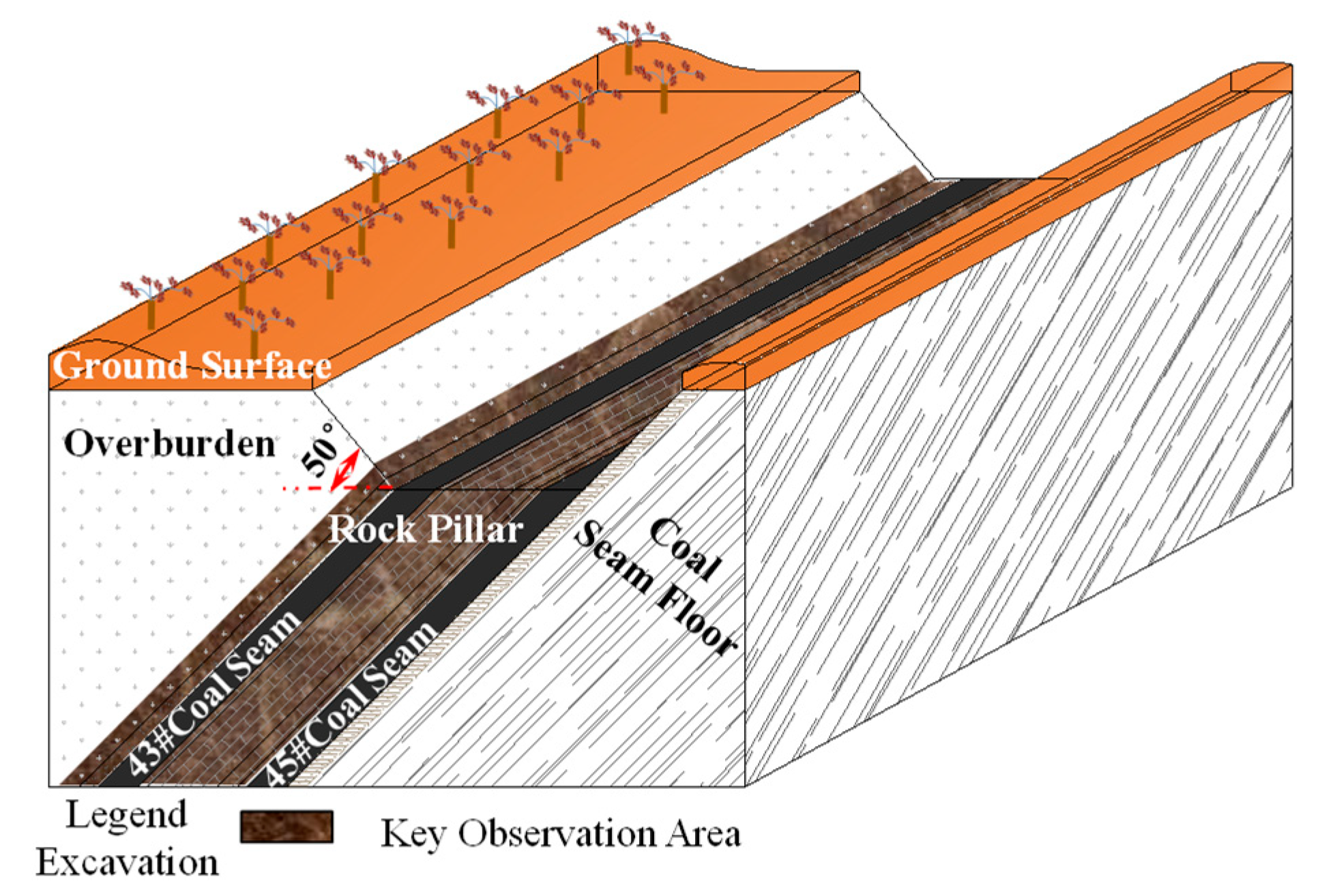
With a production capacity of 6.0 Mt/a, the Wudong coal mine is the major producer of the Xinjiang Energy Limited Company of the Shenhua Group. The mine area is located along the south edge of the Junggar Basin and extends downward from south to north at an altitude of +739.2 to +934.0 m, with a maximum relative height difference of 194.8 m and average difference of 60 m. Its coal-bearing strata comprise the Xishanyao Formation (J2X), which inclines northwest at an angle ranging between 43° and 46°.
Figure 1 shows the distribution of strata in the Wudong coal mine.
The average thicknesses of the #43 and #45 coal seams are 37.5 and 47.8 m, respectively, and their average dip angle is approximately 45°. The rock pillars between these two coal seams are compact and hard, with a thickness of approximately 80−100 m. The strata of the coal-seam roof and floor consist primarily of siltstone.
Table 1 shows the lithology of the surrounding rock.
2.2. Cut-and-fill Mining Techniques
To reflect the geological structures of the mine, we consider the cut-and-fill mining technique by separating the mining and filling techniques.
(1) Mining Technique
Two work surfaces were prepared for the #43 and #45 coal seams to perform stopping using the fully mechanized caving technique on large horizontal sections. The layout of the work surfaces has the following characteristics: (1) coal rather than roofs and floors lie above and below the work surfaces, (2) lengths of the work surfaces equal the thickness of the coal seams, and (3) level height is 25 m, mining height is 3.5 m, caving height is 21.5 m, caving ratio is approximately 1:6.2, and drawing interval is 1.6 m. The overall lengths of the work surfaces are 1500 and 1800 m, respectively, under the single-flank mining scheme.
The two work surfaces were stopped at the same time, but the mining of the #43 coal seam lagged behind that of the #45 coal seam from the viewpoint of level height. Currently, the #43 and #45 coal seams are targeted for mining at the +600 and +575 level, respectively.
(2) Filling Technique
Considering the uniqueness of steep coal seams, our literature research [
33,
34] and field survey revealed that rock beds (or roofs), which are 80 m behind the working surface, serve to stop movement and floors of coal seams are less disturbed and stable. The lag filling method is adopted to fill goafs, as shown in
Figure 2.
The filling materials for a work surface can be classified into two groups of 20% and 80% for filling the ground on the roof side. The 20% group is used to cover the goafs for preventing residual coal from exposure to the air, which could cause self-ignition. This group fills from 50 m behind to 20 m in front of the work surface. The 80% filling materials are used for filling 80−100 m behind the work surface through full use of gravity stowing. A hydraulic tamper can be used after filling to compact the filling space.
When stopping along the work surface at the next level, space is often left with the discharge of the roof coal, which triggers the roof to crack, leading to an unbalanced situation. Therefore, filling bodies move toward the next work surface by their own gravity (through gravity stowing). The strength of successive filling can be guaranteed using a hydraulic tamper to compact the filling materials.
3. Analysis of Disaster Prevention Mechanism by Filling
3.1. Analysis of Mine Disaster
Through experiments on the rock mechanics, we found that the compressive strength of the roof and floor strata of coal seams in their natural state is generally between 45.6 and 98.0 MPa, and that of most strata is between 68.6 and 98.0 MPa. The shear strength of these strata is generally between 4.92 and 9.4 MPa and mostly falls within the range 6.86–9.2 MPa. The rock strength increases with an increase in the depth.
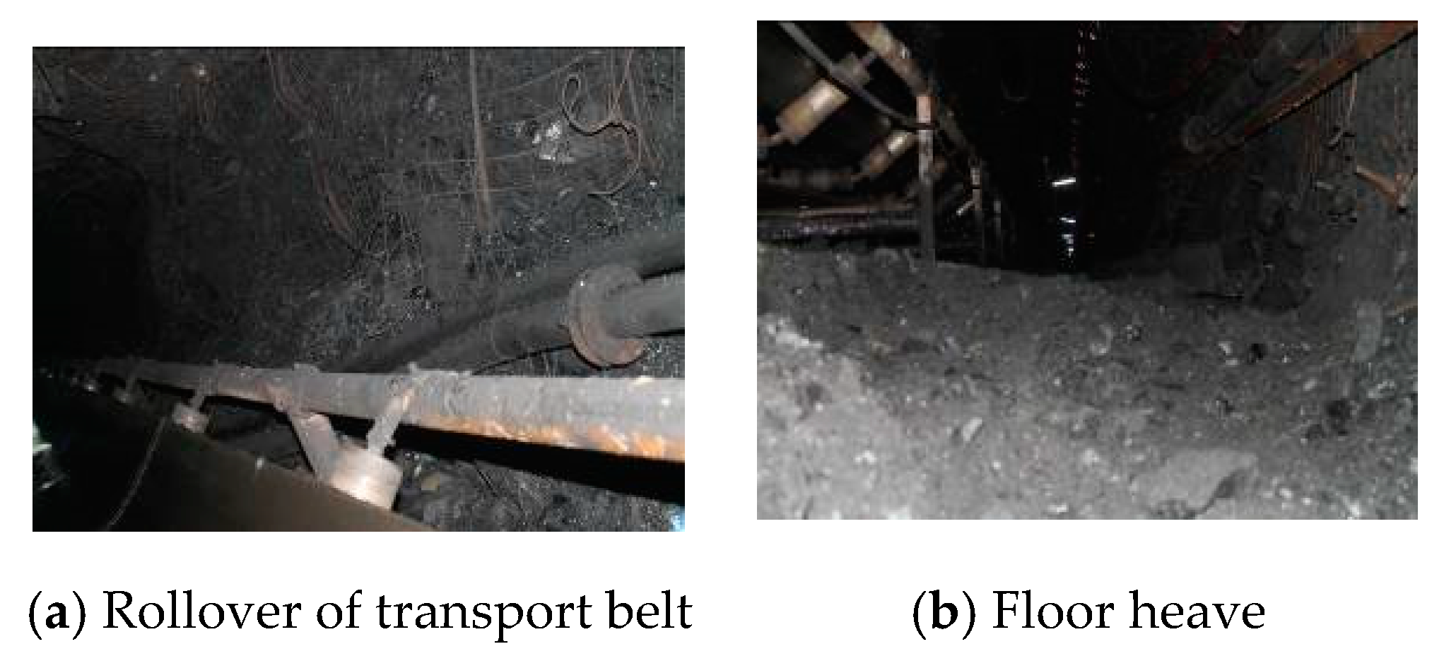
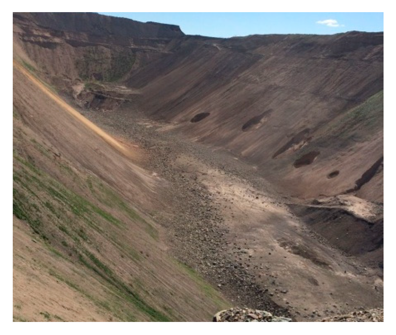
As the upper layer of the coal seam is continuously mined out, the roof strata lose bearing capacity, causing the roof strata to crack and rupture from the stress induced by sublevel mining with large-section caving. These cracks then move freely in the narrow space, causing dynamic disasters. In long-term sublevel mining with large-section caving, fractures in the overburden strata develop to a high level, resulting in the onset of strong mine ground pressure that induces roof–rock–mass caving and collapse of the overburden strata, as shown in
Figure 3. Therefore, unstable trough-shaped collapsed pits form on the ground, as shown in
Figure 4.
3.2. Determination of Filling Strength
Steeply inclined roof strata have long sections that lose support after the coal seams have been mined out, which means the roof is deflected (ω) toward the goaf under the effects of gravity and mining stress. When the deflection exceeds the bending limit, the roof ruptures, causing a chain reaction in the roof strata and repeated collapse of the ground surface. Therefore, it is necessary to use surface filling to restrain or weaken the deflection of the roof strata.
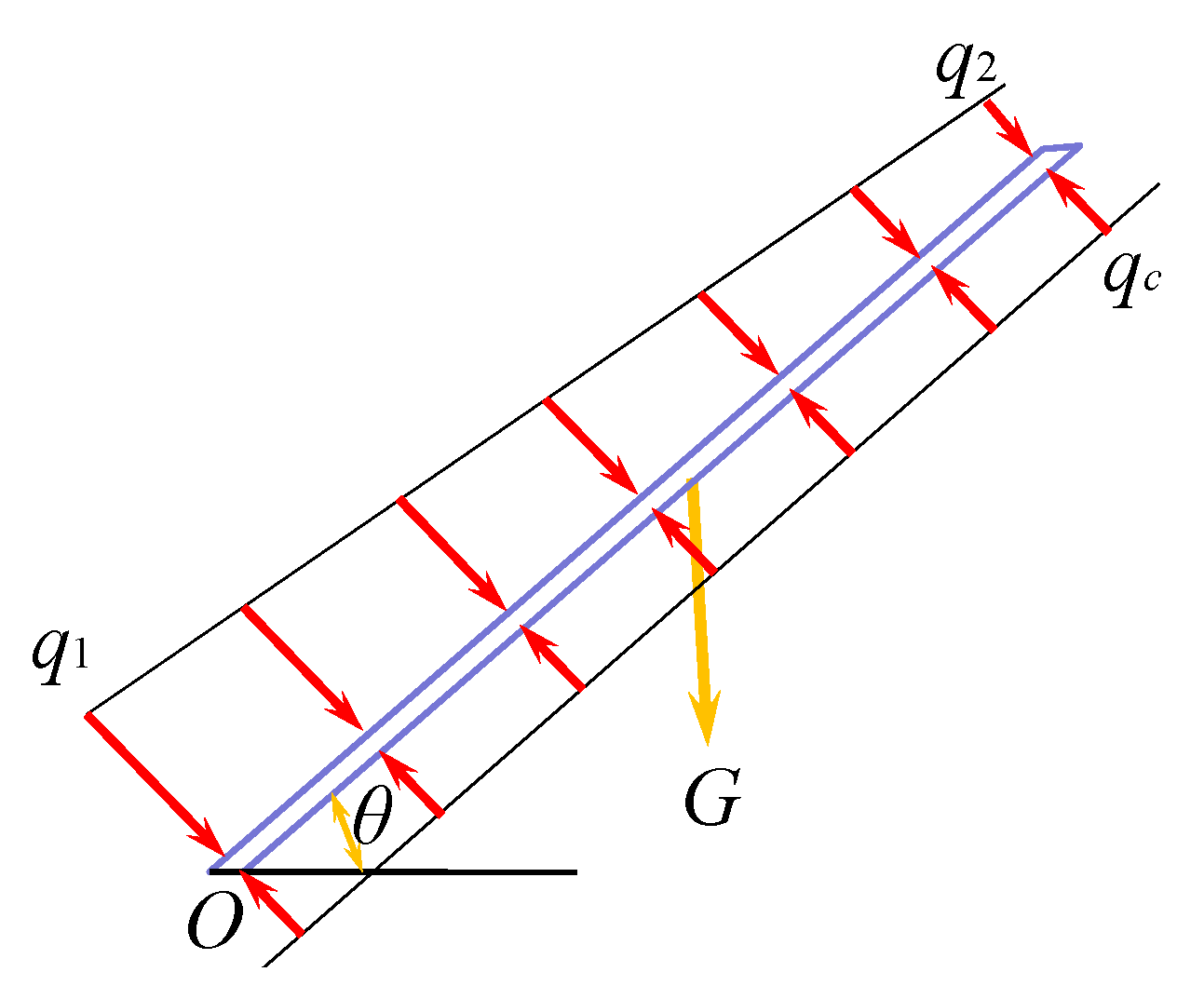
Based on the beam structure theory, the roof can be regarded as a cantilever beam, and we established a mechanical model that considers the effects of mining stress, self gravity, and supporting force of the filling, as shown in
Figure 5. The nonuniform load variations from the lower
q1 to upper
q2 are regarded as the mining stress generated in the roof strata. G is self gravity of the roof strata, uniform load
qc is the force of the filling supporting the roof strata,
θ is the inclination angle of the coal seam, and
L is the length of the beam. Therefore, the effect of cut-and-fill mining can be evaluated based on the bending deflection (ω) induced by multiple stresses on the roof strata.
The deflection is determined by superposing the bending moments of the roof strata. A mechanical model of the cut-and-fill mining of steeply inclined coal seams can be further simplified into three basic models with the bottom of the roof of the coal seam in
Figure 6 being the origin.
According to the dynamic pressure model, the bending moment equation
M1(
x) for the roof strata under dynamic pressure is as follows:
The bending moment equation
M2(
x) under gravity is as follows:
The bending moment equation
M3(
x) under the action of the upward supporting force of the filling material is as follows:
After superposing the above three basic models, the entire bending moment equation M (x) is M(x) = M1(x) + M2(x) + M3(x).
The relation between the deflection and the bending moment of the beam is as follows:
By combining Equations (4) and (5) with the boundary conditions of , , the following deflection equations can be deduced:
When
,
when
,
From the deflection equation, we can also deduce that the end of the beam has the largest deflection, as shown in Equation (8),
The filling effect is best when the maximum deflection is zero. At this point, the uniform support force that should be provided by the filling material is as follows:
According to the field experience of the Wudong coal mine, we can obtain the relation between the mining stresses q1, q2, and buried depth. Accordingly, we can calculate the strength of the filling material that is sufficient to support the roof. Equation (9) provides a theoretical basis for the on-site selection of filling materials.
According to the field experience of the Wudong coal mine, the peak stress of mining at each stage, i.e., the relation between mining stresses
q1,
q2, and buried depth, is normally 2.5 times the original rock stress, whereas the mining stress of the weakest affected area is 1.1 times the original rock stress. According to Equation (9), the uniform support force provided by the filling material should be as follows:
According to the interaction principle, the support force provided by the filling material is equal to the pressure applied on the filling material; therefore, the required strength of the filling material is as follows:
3.3. Experiment on Filling Strength
According to the abovementioned analysis, the strength of the filling material increases with an increase in the mining depth. The strength of the filling bodies at the +600 level of the #43 coal seam can be used to determine an effective filling material. As calculated using Equation (11), the compressive strength of the filling materials is approximately 4.7 MPa.
We chose gangues of various sizes as aggregates (as shown in
Figure 7a) and then matched them with adhesives with the same ratio mix of 3% industrial brine and gangue dust to obtain filling materials of different strengths, as shown in
Table 2. Rock samples with the size of 0.1 × 0.1 × 0.1 m were made for use in the mechanics experiments shown in
Figure 7b.
Based on the experimental results, we selected the third mixture ratio because it produces filling materials with a compressive strength similar to the theoretical value. We further determined the mechanical parameters of the filling material, including a tensile strength of 0.92 MPa, density of 2.354 × 10³ kg/m3, Poisson’s ratio of 0.18, and cohesion of 1.02 MPa.
4. Numerical Simulation of Cut-and-Fill Mining
4.1. FLAC3D Modeling
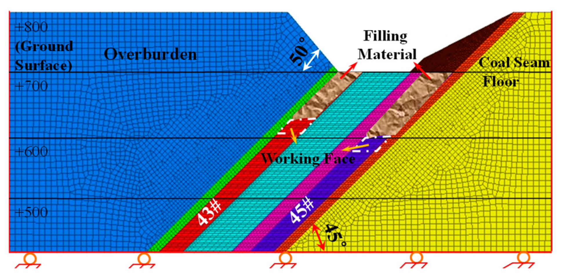
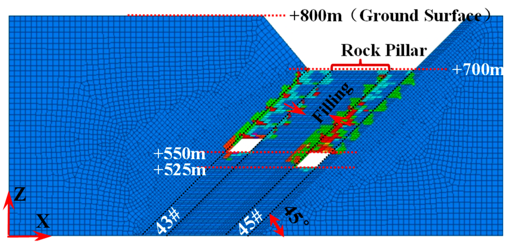
According to the on-site physical conditions, we established the numerical model shown in
Figure 8. The model is 900 × 500 × 400 m in size and is divided into a total of 346,200 grids and 358,275 nodes. The grid size of the roof and floor strata is 5 × 10 × 5 m. For calculation, we applied the Mohr–Coulomb criterion to the model.
In this model, the steeply inclined coal seams are designed to be mined in six sublevels, with the depth of the bottom level being 150 m. The elevation of the levels of the #43 coal seam ranges from +700 to +550, whereas that of the #45 coal seam ranges from +675 to +525.
The filling aggregate comprises coal gangues and construction wastes blended with stripping and dust. The adhesive is made of 3% industrial brine mixed with loess and gangue dust.
Table 3 lists the strength and related mechanical parameters of the strata, calculated according to the theory, and those of the filling bodies, which were derived experimentally.
The numerical calculations of the FLAC3D model focuses on the roof, surface, and stress disturbance. Monitoring points are located at intervals of 50, 10, and 50 m on the surfaces of the overburden strata, rock pillars, and floors, respectively. On the roof of each work face, we placed stress monitoring points at 25-m height intervals.
4.2. Stress Variation Characteristics
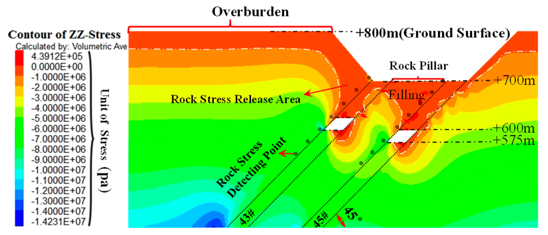
When a coal seam is being mined, the filling body, residual coal and rock, segmented coal seam, and unexploited coal seam occur from top to bottom.
Figure 9 shows the stress disturbance during cut-and-fill mining (taking 270 m on the y-axis as an example). Coal-rock joints and local goafs above the work surface are stress relief zones, and the other goafs are in a stress-free state.
Results show that after filling, the rock strata, filling areas, and goafs (broken roofs) press against each other to form a temporarily stable structure. With an increase in the mining depth, the filling body will slide downward as the rock is disturbed.
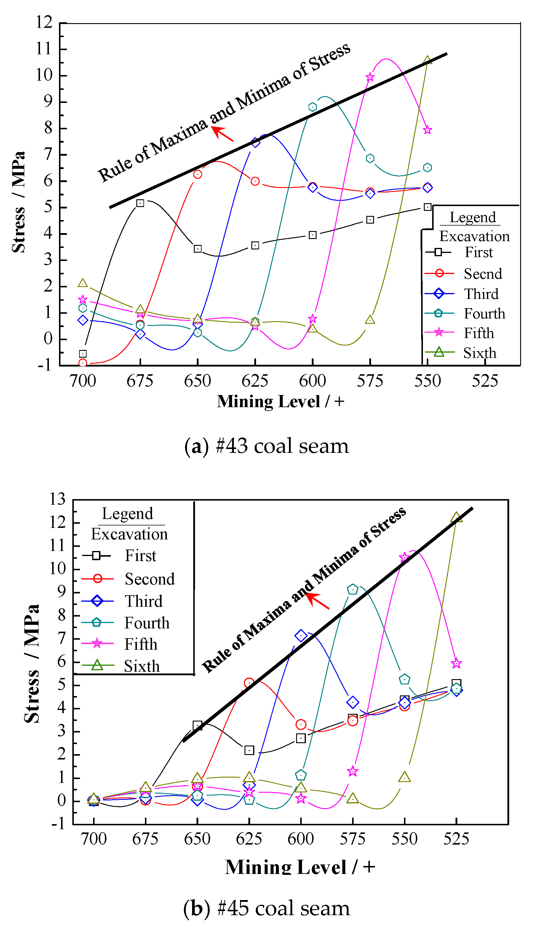
As shown in
Figure 10, we calculated the stress disturbance in the roof strata above the work face at six levels, and performed a regression analysis of the stress variation curve using Equation (12), given as follows:
The degrees of fitting between the results obtained using Equation (12) and original stress curves of the #43 and #45 coal seams are 0.989 and 0.996, respectively. In the equation, a and b are constants.
Overall, the peak stress disturbance of the roof strata after filling increases linearly, and we found the peak stress variation range of the #43 coal-seam roof to always be greater than that of the #45 coal-seam roof. This indicates that the filling body changes the stress distribution law and establishes a new equilibrium structure by interacting with the surrounding rock.
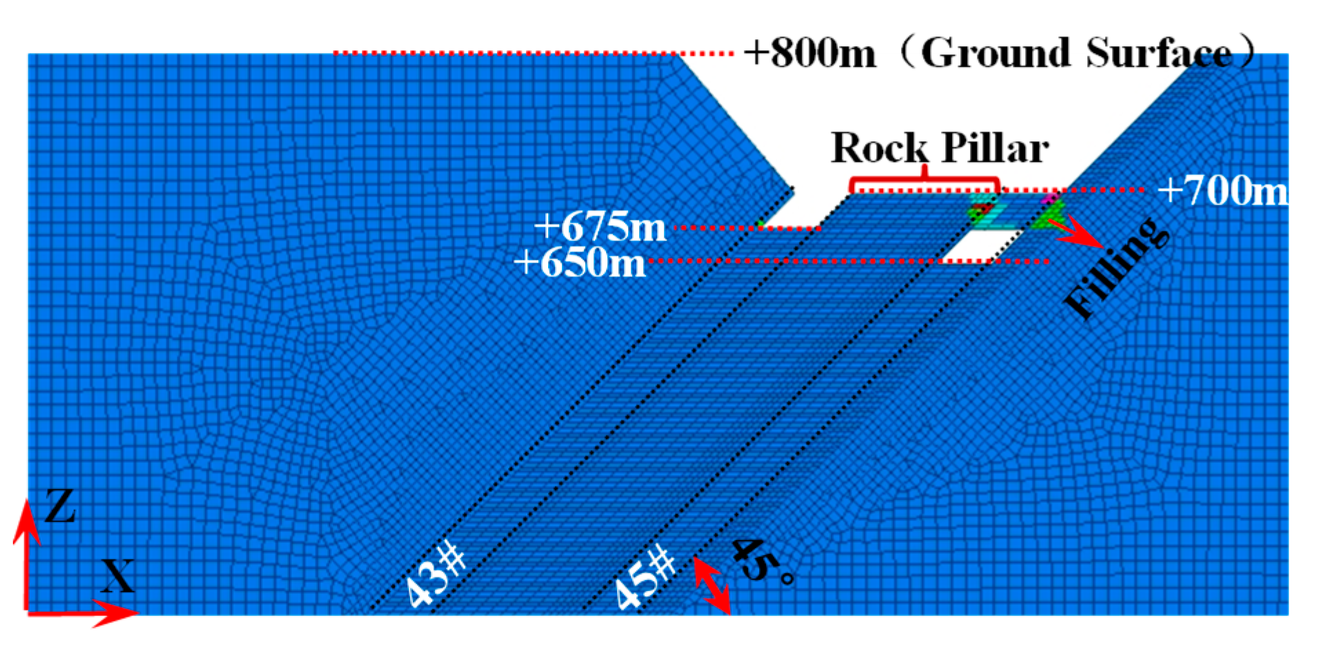
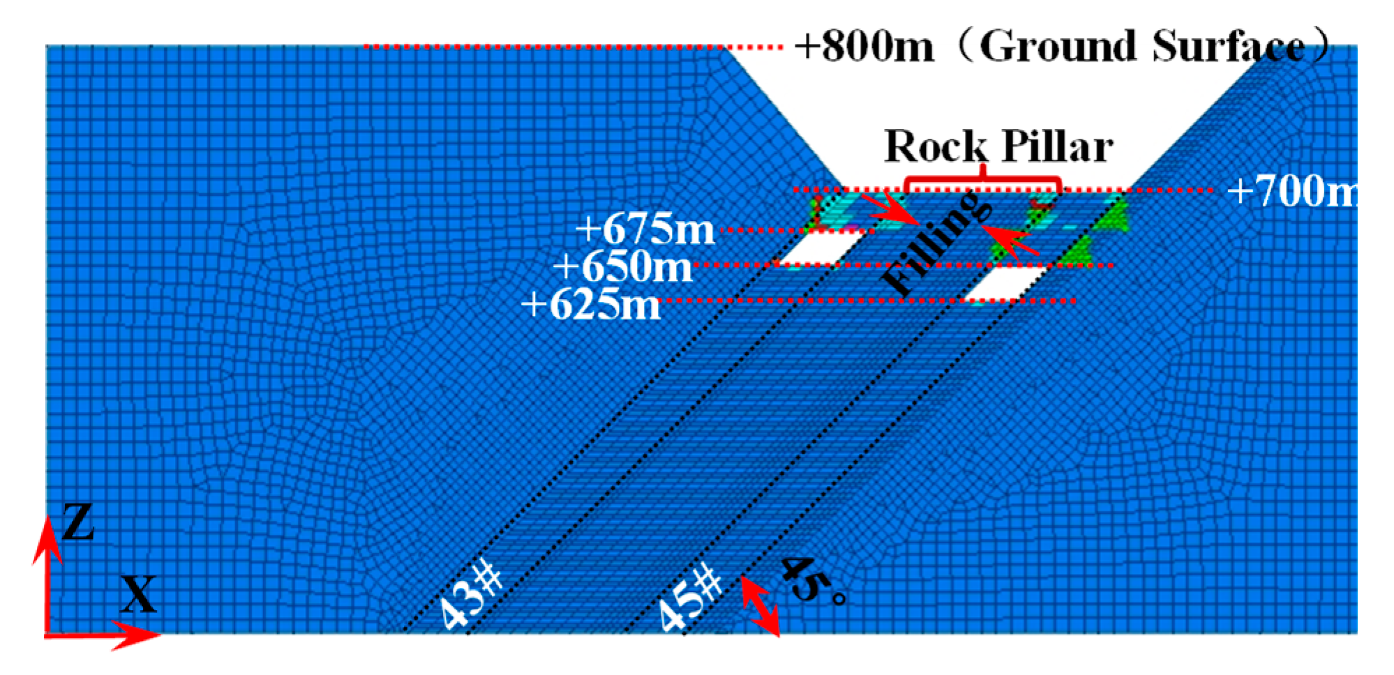
4.3. Variation Characteristics in Plastic Zone
Continuous mining activity reduces the overall strength of strata and leads to the gradual expansion of failure zones in the strata. As mining deepens and horizons vary, the scope of the plastic zone further expands, and balance of the rock stress field is disturbed from time to time. We determined the occurrence of plastic zones during six excavations, and the results are shown in
Figure 11,
Figure 12,
Figure 13,
Figure 14,
Figure 15 and
Figure 16.
After the first excavation, we found no plastic failures in the roof or floor of the #43 coal seam. After filling, plastic zones were observed in the roof and floor of the #45 coal seam, and the roof was expanding.
After the second excavation, plastic failures were observed in both the roof and floor of the #43 coal seam. After two filling procedures, the #45 coal seam experienced plastic failures at the +625-m level similar to those of the first excavation. Therefore, we know that plastic failures occur in the roof and floor under the combined action of coal discharge and filling. The filling bodies and roof and floor press against each other to maintain balance and prevent movement of the overburden strata.
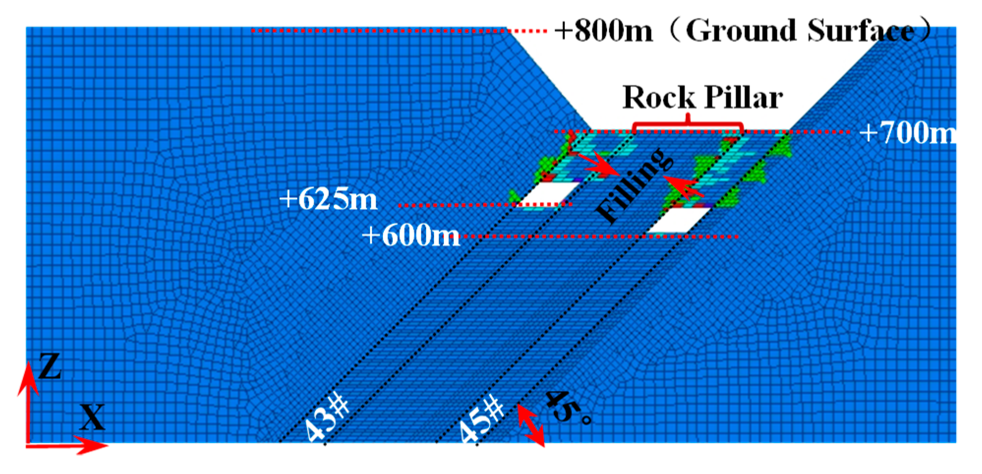
After excavation intensifies, plastic failures were observed in local areas of the roof of the #43 coal seam and at the bottom of the filling bodies of the #45 coal seam, suggesting that with an increase in the mining depth, the roof can collapse in response to mining. Filling bodies are the first to fail when the surrounding rock rebalances itself.
After the fourth excavation, plastic failures were observed at both work surfaces, and as mining deepens, roofs broke and fell into the goafs to become part of the filling bodies.
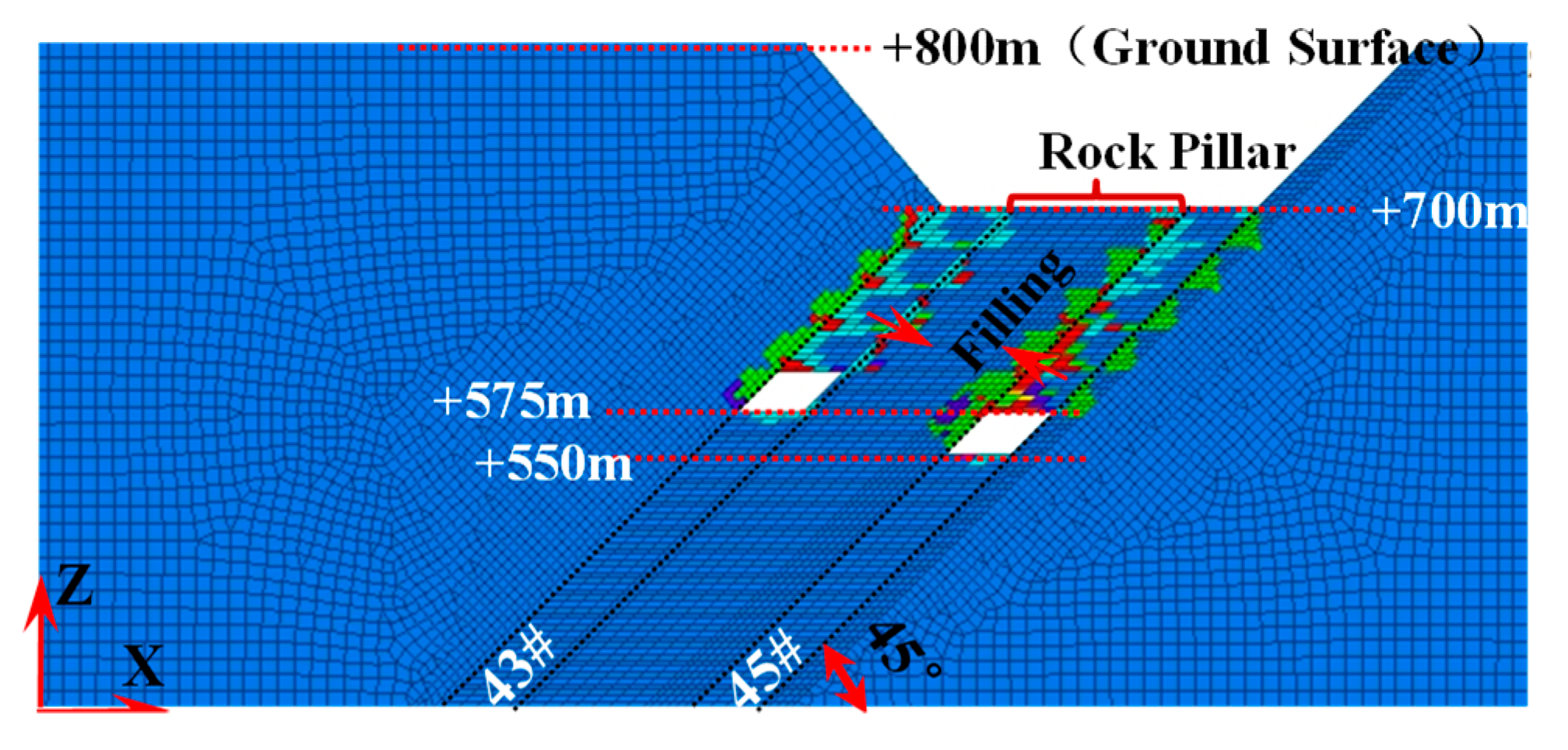
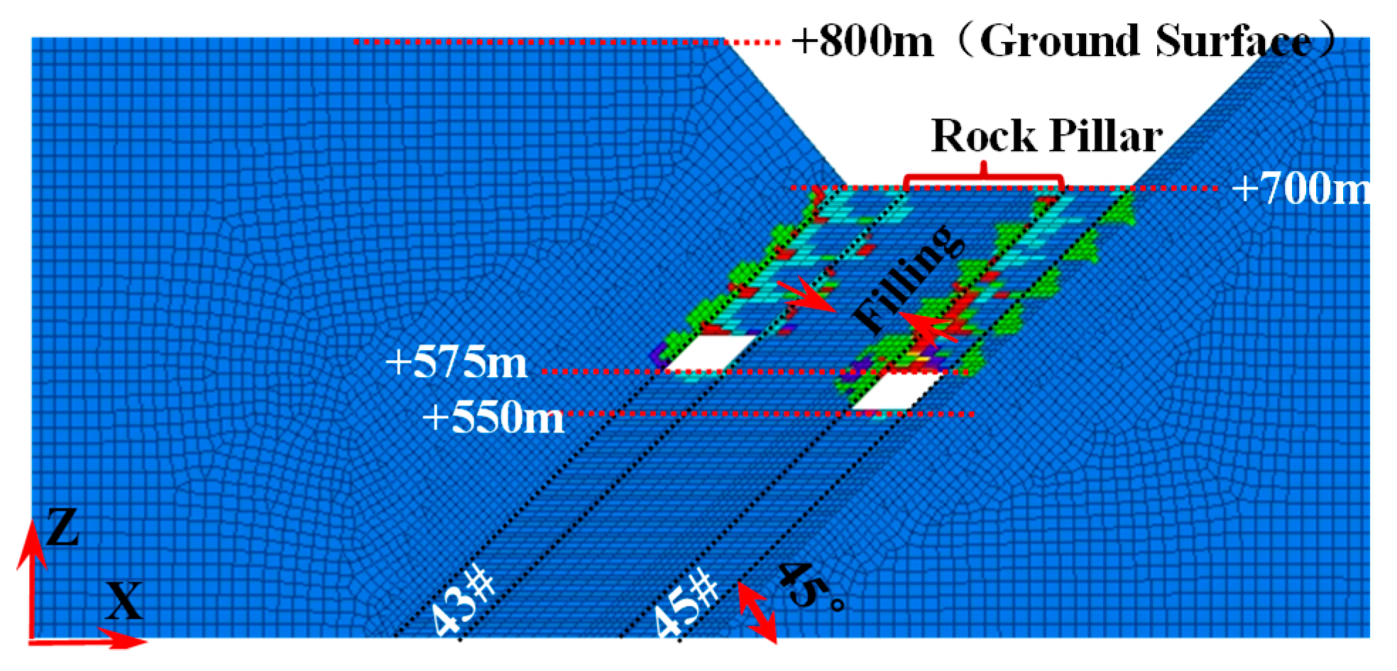
The overburden strata exhibited similar movement after the fifth and sixth excavations. The plastic failures in the roofs of both work surfaces are connected, and the bottom of the filling bodies experienced overall plastic failure. Due to the mining activity, deep filling bodies comprised collapsed roofs and filling materials, and as roofs and floors are broken, filling bodies can move downward more easily.
During the sixth excavation, no extensive plastic failure was observed on the whole. Although failures were observed in both the filling bodies and surrounding rock, the inside of the filling body remained comparatively intact. As the mining deepens, the plastic failures tend to be more severe along the roofs of the work surfaces but remain stable along the floor.
Therefore, we speculate that after filling, the filling and surrounding rocks push against each other and finally achieve a balance, preventing the overburden strata from falling and rock pillars from breaking and slipping. As mining extends downward, the roofs of the coal seams can collapse and provide an advantage for the downward movement of filling bodies. When deep mining is performed, broken roofs and filling bodies combine and become the filling bodies of the goafs.
4.4. Ground Surface Variation Characteristics
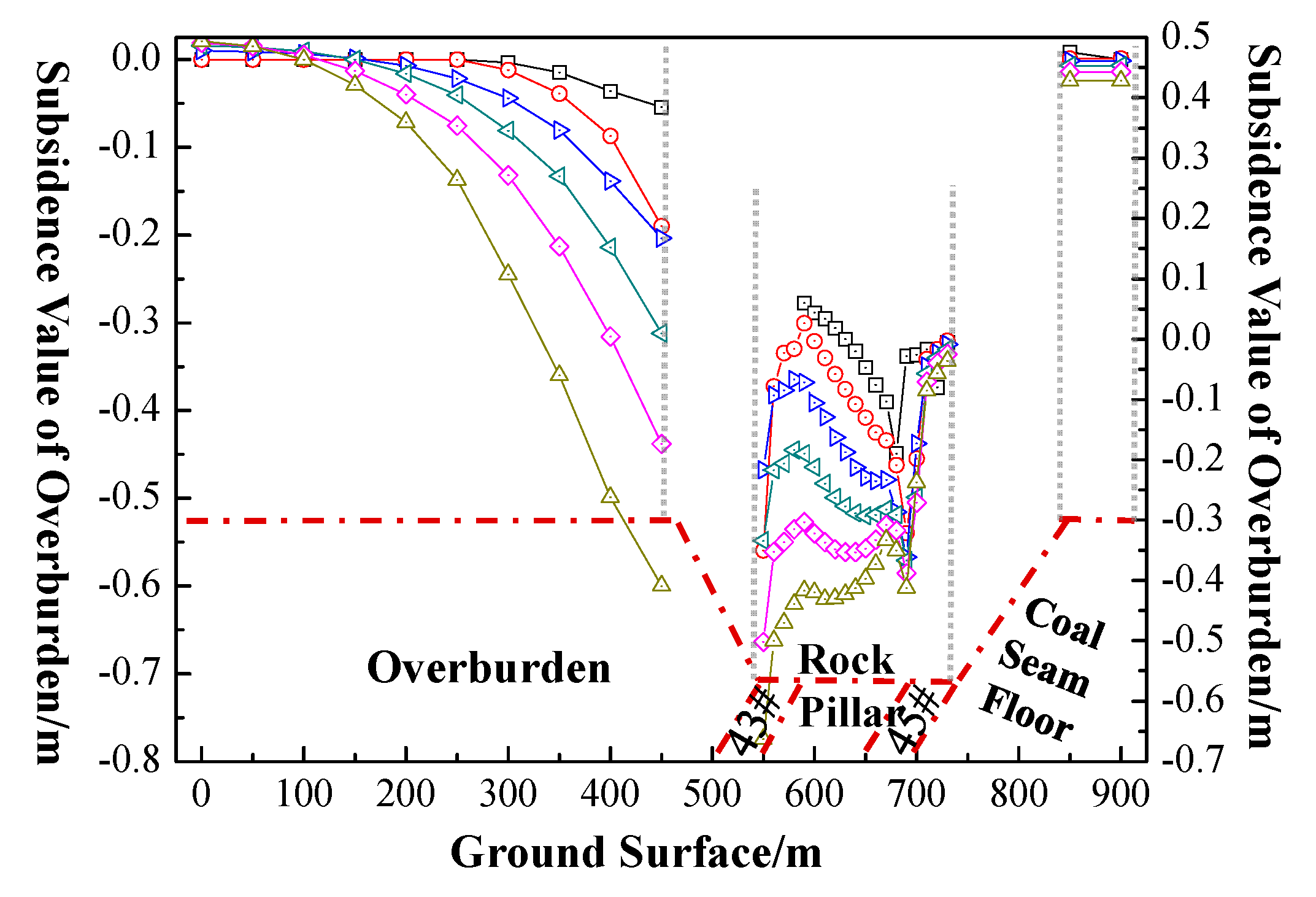
We determined the ground surface subsidence of rock strata at the same ground level after cut-and-fill mining, and the variation is shown in
Figure 17.
After filling, the surface settlement increases with an increase in the mining depth, but the subsidence remains within 1 m. The combined rock formation (the top of each coal seam) experiences the largest settlement, and the subsidence of the roof of the #45 coal seam was less than that of the #43 coal seam. With an increase in the mining depth, the rock pillars tend to be moderate, and the amount of subsidence at the bottom of the 45# coal seam was relatively large. Upheaval occurred at 0–100 m of the overburden.
5. Engineering Practice
Currently, the +600 and +575 level of the #43 and #45 coal seams, respectively, are being mined in the Wudong coal mine. The designed length for mining the #43 and #45 coal seams is 550 m. The adhesive consists of 3% industrial brine along with loess and gangue dust mixed in the ratio of the third type listed in
Table 2, with the filling aggregate composed of coal gangue and urban construction wastes blended with stripping and dust. As roofs of the work surfaces can crack and rupture, filling is performed while taking full advantage of the gravity of the filling material. Filling lags are placed at the working surface for 80 m and on the ground by the overburden and rock pillar sides. The amount of filling material used each time in the #43 and #45 coal seams is approximately 240,730 and 181,000 m
3, respectively. A total of 28 working days are needed per month to accomplish the filling work. The distance advanced during each shift is 6.4 m, representing the filling amount each day.
After the aggregate is filled, grouting is performed from the ground surface borehole to increase the density of the ground cover and to ensure there are no air leakages. A total of 20% of the filling material was used from 50 m behind to 20 m in front of the work face to form an isolated layer, with the volume of filling materials being 48,146 and 32,600 m3. The remaining filling materials are used as filled-lagging work faces from 80 to 170 m. Filling material is obtained through blending fully aggregates, adhesives, and dusts on the ground, and is then pumped into the total goaf from its top under its own gravity.
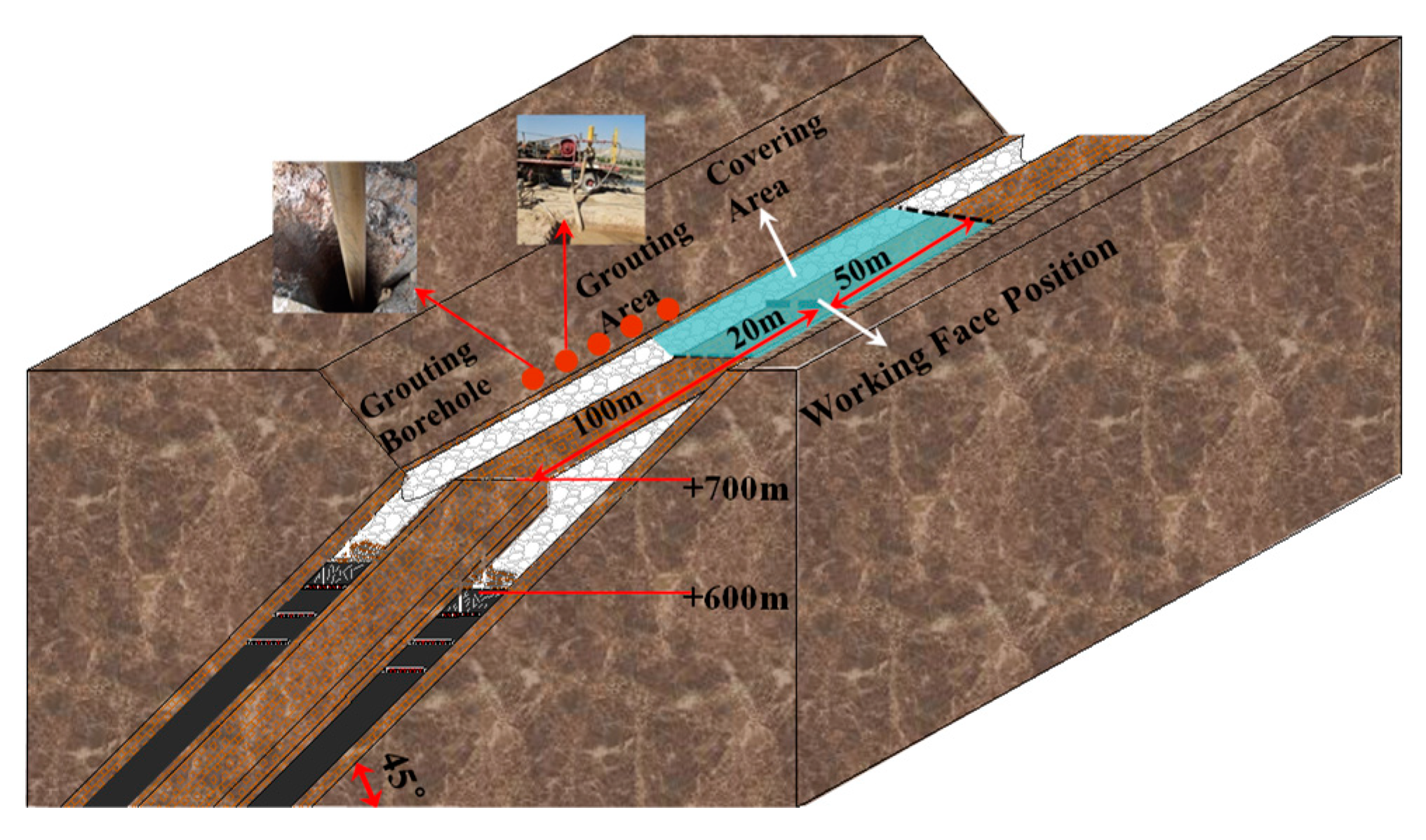
As observed in the field, there should be about one week for filling material to reach a steady status; the advanced distance of the working face is 45 m per month. After filling, in both the #43 and #45 coal seams, four hydraulic tampers are used for tampering 50 m behind the filling position until no obvious subsidence is seen in tampering positions. The integral implementation plan is shown in
Figure 18.
Table 4 lists the parameters of the cut-and-fill mining of the #43 and #45 coal seams.
6. Effect Test and Evaluation
6.1. Detection Technology of Underground Geological Radar
Geological radar is an intelligent monitoring method that can indicate the distribution and content of buried strata using wireless electromagnetic waves to detect their dielectric constants.
Underground strata are a low-loss dielectric material, for which the failure condition and stability can be evaluated based on the intensity of the back waves of pulses.
Figure 19 shows the detection principle. The back waves of an electromagnetic pulse emitted by a transmitter can reflect the strata features by different dielectric constants of the strata. Before the ground surface was backfilled, the coal-seam roof achieved stability after a period of movement, whereas the goaf was grouted when the upper level of the coal seam was mined. Thus, the roof was broken, which means the interface either increased or decreased. Consequently, the difference in the dielectric constant on the two sides of the interface widens and can weaken or enhance the electromagnetic wave signal. The backfilling effect and condition of large sections of high roofs can be evaluated by analyzing the images acquired by the geological radar, providing a scientific basis for the assessment of the roof stability.
6.2. Testing Scheme
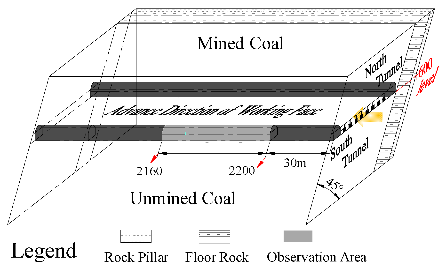
To ensure safe mining, presplitting blasting is conducted prior to mining as the coal seam roof and floor in the north mining area of the Wudong coal mine are both rigid rock. Presplitting blasting releases the rock stress and roof coal seam; therefore, the filling material can move downward. Tests were conducted in the south roadway of the #43 coal seam at the +600 level and #45 coal seam at the +575 level to comprehensively analyze the stability of the strata and the filling effect on the goafs. As an example,
Figure 20 shows the #43 coal seam at the +600 level to illustrate the detection scheme for goafs.
6.3. Effectiveness Analysis
The goaf was detected from the south roadway at the +600 level of the #43 coal seam, with the detection scope ranging from the +600 level to the overburden goaf.
Figure 21 shows the difference in the scanning detection feature of the interfaces in the roof strata along the strike direction.
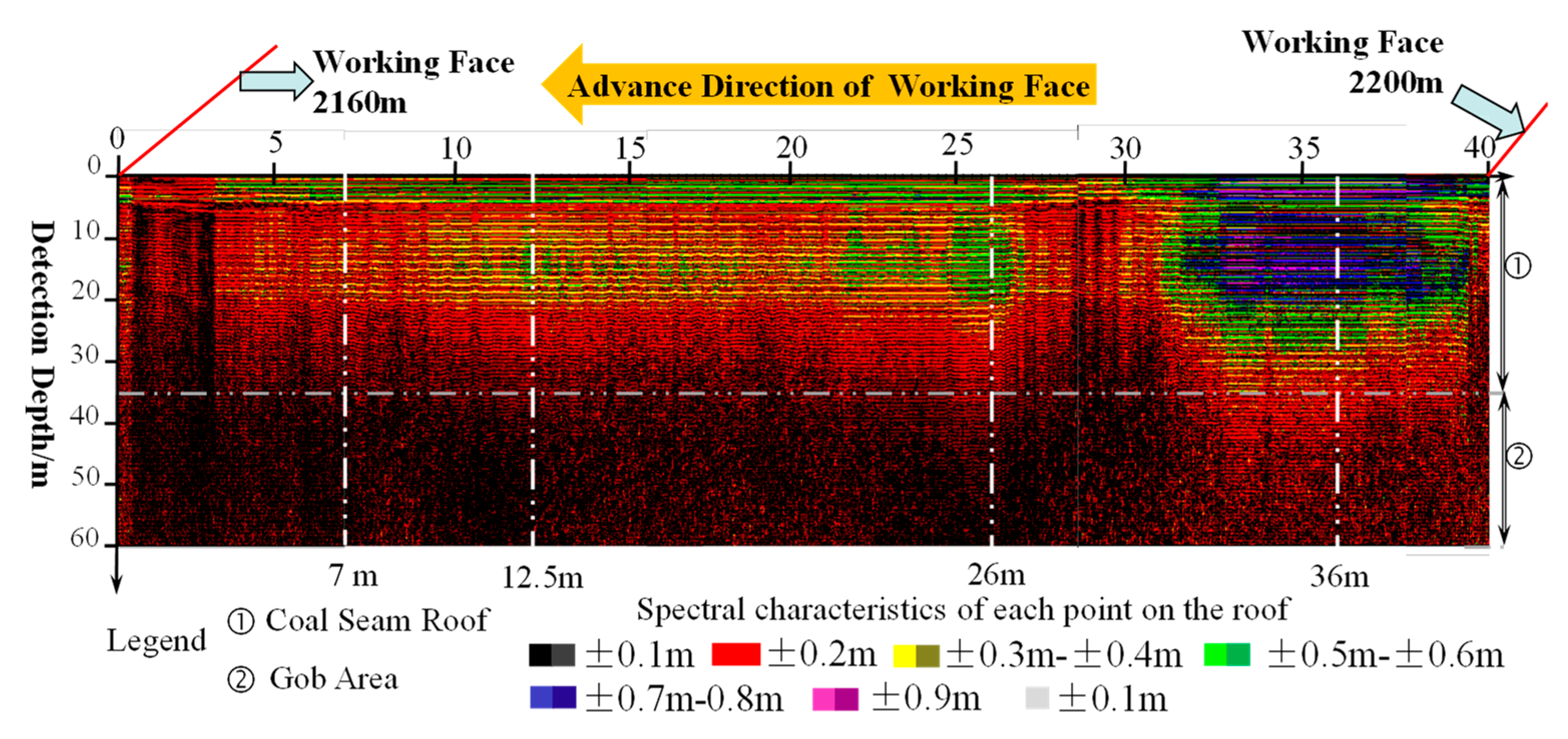
The incident waves are all reverse waves, and the absorption of electromagnetic wave energy is based on the degrees of cracking of the roofs. According to the scanning result at the +600 level, the amplitude energy can be obtained according to color, including black, red, yellow, green, blue, pink (purple), and white.
The detection reaches 60 m in depth, with the coal seam approximately 0–35 m in depth and the goaf at approximately 35–60 m. Due to filling, the overlaying goaf at the +600 m level is mainly in black mixed with red. The zone near the work face is mainly in green, whereas other zones are green mixed with red. There is a “dual zone,” wherein the color changes for coal seams along the work surface. Some violet local zones range from 32 to 37 m along the strike of the work face in the top coal area (affected by the leading crack).
Based on the scanning characteristics, we determined the spectrum characteristics at 7, 12.5, 26, and 36 m, as shown in
Figure 22.
The energy of the electromagnetic wave in the top coal area decreases from 36 and 26 m (12.5 m) to 7 m. The electromagnetic wave energy of the goaf is 36 m, which is the highest, and the other three locations are basically the same. This indicates that the top coal area at the front of the work face is broken and compacted by the filling material and work face. The goaf is filled with the filling and caving roof strata. From the viewpoint of the scanning results, we can conclude that, overall, the filling materials in the goafs and fractures above the work face are fully developed, and the filling body has merged with the caving roof, which will collapse with the release of the top coal.
7. Conclusions
Through theoretical analysis, we found that the compressive strength of filling materials for the goafs of 45° steep coal seams is related to the mining depth and type of strata, as expressed by the equation σc = 0.91γH. The ratio of filling materials is determined through strength calculation and the parameters of filling material are obtained through petrological experiments.
Based on the numerical calculations for cut-and-fill mining, after filling, the overburden strata remain stable with no large-scale tensile fissures occurring on the ground. The stress disturbance peak of roofs increases linearly, and there are areas of local stress release in goafs. Some failure zones are caused by stress disturbances in the roofs and floors of work faces, and they collapse toward goafs as the work surfaces are being stopped, forming new filling bodies along with the filling materials.
According to the on-site detection results, goafs become dense after filling, and filling bodies mix with caving roofs and move downwards as the top coal is discharged.


