Article

Research of Modified Atomizers and Their Application for Moistening of Air-Cleaning Device Charges

by
Pranas Baltrėnas
and
Edita Baltrėnaitė-Gedienė
*
Institute of Environmental Protection, Vilnius Gediminas Technical University, Saulėtekio al. 11, Vilnius LT-10223, Lithuania
*
Author to whom correspondence should be addressed.
Sustainability 2019, 11(19), 5522; https://doi.org/10.3390/su11195522
Submission received: 13 September 2019 / Revised: 30 September 2019 / Accepted: 1 October 2019 / Published: 6 October 2019
(This article belongs to the Special Issue Green Technologies in Air Treatment)

Abstract

:
The size of sprayed droplets is a very important parameter that influences the operational efficiency of air-cleaning device charges. It is desirable for atomizers to spray droplets that are dispersed as much as technically and economically reasonable and possible. Fine dispersion spraying ensures effective moistening of the air-cleaning device charges, as well as an optimal consumption of water or other liquids. Three modifications of special atomizers were used for experimental analysis. The atomization of liquid and spraying in the special atomizer occurs when two frontal streams confront each other. Frontal streams are formed by an inner shield located in the special atomizer. The experiment was conducted using different spraying pressures, namely: 6 bar, 4 bar, 2 bar. The evaluation (performed using a microscope) of the size of sprayed droplets shows that the best (finest) spraying was by the special atomizer of modification 3. The depth of the channel of the inner shield is the parameter that has the biggest influence on the size of sprayed droplets. The special atomizer of modification 3 produces droplets with the following size distribution and rates: ≤0.05 mm—63.2 vol%; 0.2–0.6 mm—28.3 vol%; 0.6–1.0 mm—8.1 vol%; ≥1.0 mm—0.4 vol%.

1. Introduction

Industry began cleaning air by a wet method using absorption as the key physical parameter from 1900 onwards [1]. Absorbers as waste air cleaning devices may be categorized as physical, chemical, and biological absorbers, and are mainly used for the abatement of polar compounds. Biological processes may be further categorized according to the amounts of water used for bioscrubbers (for polar compounds; big amounts of water [2]), biotrickling filters (both for polar and lipophilic compounds; moderate amounts of water [3]), and biofilters (mainly for lipophilic compounds and odor; low amounts of water [4]). The biological processes underline the relevance of optimal spraying conditions, both to the size of spray droplets to avoid an insufficient dispersion of the water phase as well as the volume of the water phase sprayed in total. The efficiencies of (biological) waste air treatment may severely depend on the techniques and the corresponding irrigation densities used [5,6]. Furthermore, spraying technologies are commonly used to stabilize biomass in trickling filter processes [7].
Air-cleaning devices (or their charges) must be moistened constantly; namely, they must be designed together with hydraulic systems [8]. The atomizer is one of the fundamental elements of the hydraulic system. The atomizer is equipment that facilitates and enables spraying; namely, it is a device that atomizes liquid by means of the peculiarities of its form [9]. The spraying—i.e., formation of the initial droplets and their abruption—normally is regulated by the flow in the interior of the atomizer [10,11]. The following actual droplet diameters (sizes) are predominant in the industrial area: 500 µm, 1200 µm, and 5500 µm [12]. Spraying, in case of insufficient dispersion, wastes the water, so it is important to support optimal spraying. For the optimal moistening of charges used in air-cleaning devices, it fully suffices to spray droplets of the middle size, i.e., with the diameter of 1200 µm. The character of the spraying type depends on the sort of energy that is used for atomization of the liquid. Such energy might be in the liquid itself: atomizers that are running by pressure or a.k.a. hydraulic atomizers. In addition, energy might be mechanical (rotating or disk atomizers), electrical, or acoustic. The six main types of the atomizers are described below. Pressure or hydraulic atomizers are such a type of atomizers that are mostly used [13]. Pneumatic (or air) atomizers are pneumatic atomizers (twin-fluid atomizers) that typically use the kinetic energy of pressurized gas that interacts with the liquid surface to disintegrate the liquid. If the diameter of the air vent and tag angle of the atomizer are increased [14], the rate of spraying will decrease. In twin-fluid atomizers, their spray is even. The operating principle of rotary (or disk) atomizers is based on the interaction of a quickly rotating disk or wheel with liquid, which is affected by the centrifugal force. Although the distribution of the sizes of droplets that are sprayed by rotary atomizers are more equal than those by hydraulic atomizers [15], the dependence on the energy of the rotary atomizers for one kilogram of liquid is repeatedly major [16]. Ultrasonic atomizers either directly use the acoustic energy in a gaseous atmosphere or indirectly use the vibrational energy of an ultrasonic excitated surface. Within an electrostatic atomizer, an electrically charged liquid is accelerated in an electric field, thereby forming an accelerating tiny liquid jet that finally breaks down into fine droplets at the tip [17]. The main failing of spraying of such a type is that mini fraction droplets might be received only in small quantities [18]. Monosize droplet generation is developed in some fields of the industry, where sprayed droplets must be of equal size [19]. The disturbance generates waves of uniform size that lead to the continuous breakup of the liquid jet into identical droplets [20].
The emphasis in this article is on a hydraulic special atomizer and its spraying performance. Droplets produced by this atomizer are made by the collision of two frontal streams. The said atomizer must be called “special” by the reason that the usage of two advanced streams is to be regarded as a new method to obtain spraying. Moreover, Lawrence and Wang together with other scientists [21] abstracted on the following types of atomizers that are used in biotechnology: Berlin, Sacrament, New York, and Dresden atomizers. According to the qualification of the atomizers made by the scientists, this special atomizer will be called the Vilnius atomizer. In the process of selecting an atomizer type, it is important to know what type of spraying is optimal, i.e., how the greatest effect can be achieved with minimal consumption. The need to assess droplet size distribution is critical [22]. The types of spraying should be abstracted based on their specific parameters as follows: (1) hollow cone, (2) double cone, and (3) plane spraying [23]. The hollow cone spraying is used where small droplets and high efficiency are required. During double cone spraying, the surface is fully covered with droplets of normal or of extensive size. Plane spraying is usually used as a “knife” of a plane, strong, or tight stream—for example, in situations when paper mass is cut in paper plants. Spraying velocity is very important for such a type of spraying [23].
The size of sprayed droplets is very important when selecting an atomizer [22]. The size of the sprayed droplets depends on the characteristics of the liquid, the effectiveness of the atomizer, the spraying pressure, and the spraying angle. The lesser the spraying pressure, the bigger the sprayed droplets, and vice versa. The higher spraying pressure generates smaller droplets [12].
One of the important problems with the hydraulic atomizers spraying water is the wear and tear of these atomizers (characteristic of abrasiveness) [24]. A typical symptom of the wear and tear of the atomizer is the unacceptable growth of ineffectiveness caused by the erosion of the atomizer’s inner structure [25]. The material of which the atomizer is made is very important for the functioning of the atomizers. Nevertheless, the environment also greatly affects the development of corrosion [26]. Water (liquid) that flows also contains various sediments and microorganisms; it may be the reason for the stoppage of atomizers or pulling of the film, which worsens the effectiveness of the spraying [27].
Air-cleaning equipment for which watering is required includes physical scrubbers (e.g., non-biological scrubbers) and biochemical reactors (e.g., biofilters, biotrickling filters, and bioscrubbers). In the physical scrubbers, the liquid (water) gets into interaction with gas to absorb gas and solid particles to increase their sedimentation [8,28]. Biofiltration uses microorganisms fixed to a porous medium to break down the pollutants present in an air stream. Some form of water addition is used to control the moisture content and add nutrients [29]. In biotrickling filters and bioscrubbers, gas contaminants are absorbed in a free liquid phase prior to biodegradation by either suspended or immobilized microorganisms [30]. The chemical effect (chemical reaction) and biochemical effect (reaction catalyzed by enzymes) are favored by the presence of moisture.
In a biofilter during the air-cleaning process, the molecules of the supplied pollutant slowly move across the charge. After the pollutants have migrated from the gaseous to the watery stage, they are involved in fermentation, and are disrupted by microorganisms that are located inside the biofilter charge [31]. The charge that is irrigated increases the aerodynamic resistance of the layers of the biofilter. This reduces the time of the interaction between the pollutants and the microorganisms, resulting in a reduction of cleaning efficiency [32].
It is evident that watering highly influences the effectiveness of cleaning in the process of using air-cleaning technologies [33,34,35]. For this reason, research and analysis of the special atomizer, aimed at decreasing the droplet size and increasing the distribution of the sprayed liquid, is described in this paper.
The aim of this article is to examine the effectiveness of the atomizers of special structure and to assess the suitability of the atomizers of the above-mentioned structure for watering the equipment for clearing of the air.

2. The Research Methodology

The experiments for assessing the sizes of the droplets were performed in the Institute of Environmental Protection at Vilnius Gediminas Technical University (Lithuania). The system of the experiment included the experimental atomizer, which was connected to the water supply pipe by a fenestrated hose. The highest pressure inside the water supply pipe was 6 bar. After the fenestrated hose was connected, the pressure was changed with a connected manual valve (Figure 1).
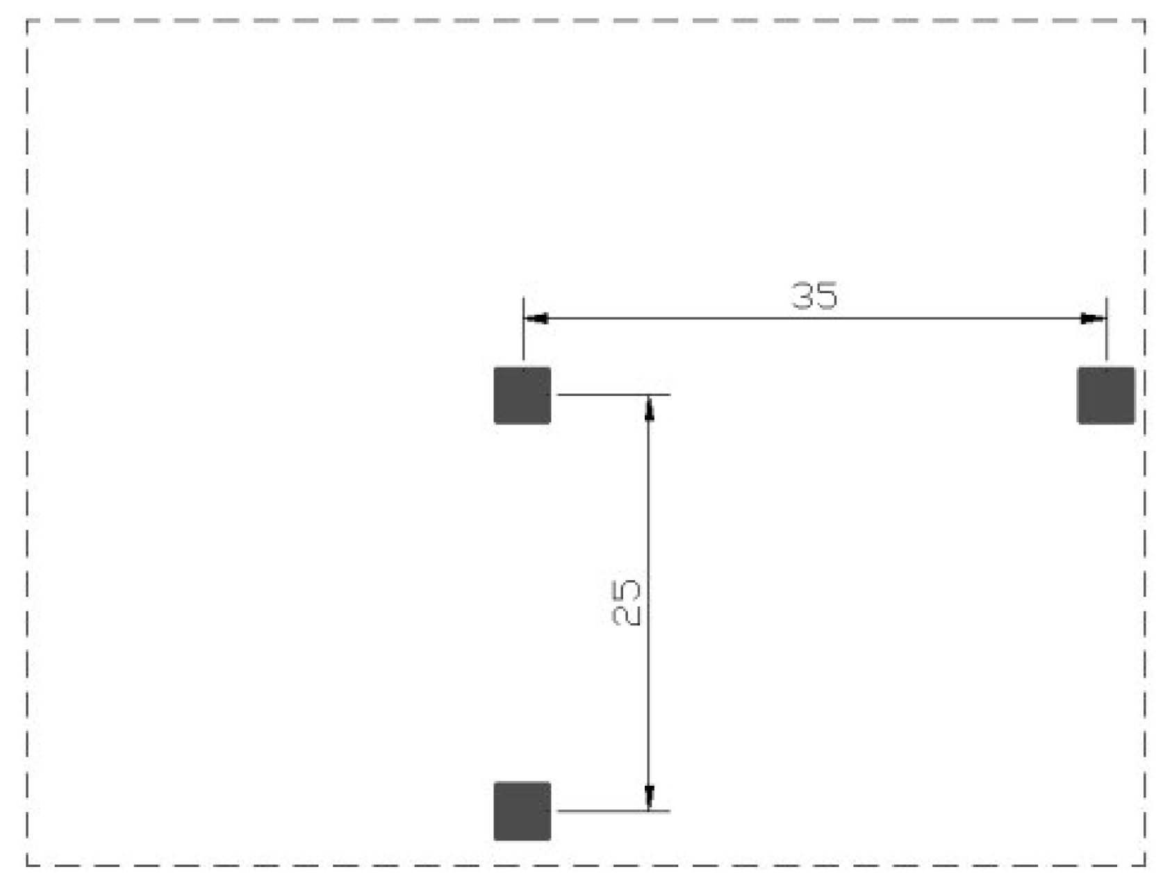
The water was sprayed upon a square with dimensions of 3 cm × 3 cm (Figure 2); additionally, it was divided into nine smaller squares of 1 × 1 cm in order to determine the sizes of droplets more accurately. A smaller square that was made of plastic of blue color was used for insulation of the live wires. Such material was selected because it is waterproof. Moreover, its surface was matted and nonslip, so when the droplets fall on such a surface, they do not change their form. The atomizer was removed from the affected surface at a distance of 60 cm.
The affected surface (Figure 1, Figure 2, Figure 3, Figure 4, Figure 5, Figure 6 and Figure 7) was a sheet of organic glass with dimensions of 100 × 100 cm, onto which water was sprayed. Organic glass does not absorb water; consequently, the sizes of the droplets do not change after spraying.

2.1. The Course of the Experiment

The affected surface that was a sheet of organic glass (the size of 100 × 100 cm) was prepared. Three small squares the size of 3 × 3 cm were placed on the sheet: (1) at the center of the sheet; (2) at the periphery of the sheet that was 25 cm from the center; and (3) at the periphery of the sheet that was 35 cm from the center. Figure 2 represents the scheme of the position of the sheets. Such a pattern of locating was selected because the dispersion and concentration of the droplets change when receding from the center. Then, the valve of the water supply pipe was opened. The desirable pressure was established by positioning the valve. The experiments were performed at the following three different pressures: 6 bar, 4 bar, and 2 bar.
The valve that was located before the atomizer (Figure 1) was checked for control purposes, and then whether the pressure inside the fenestrated hose was proper was checked as well. It was also checked whether everything was hermetic, and if not, whether everything was clamped with clips. Control spraying was performed into a plastic pail of 12 L. After we were sure that everything was operating acceptably (everything was hermetic and proper pressure was established), the valve was closed (Figure 1, Figure 2, Figure 3 and Figure 4), and the conclusion was that we were ready for the experiment.
The distance (60 cm) from the prepared affected surface was measured by use of a belt ruler. The atomizer was kept above the center of a sheet of organic glass of 100 × 100 cm. Three small plastic squares the size of 3 × 3 cm were placed onto the organic glass in such an arrangement as in Figure 2. After the position of the atomizer above the affected surface (at the center) was fixed, the manual valve was opened and closed by a sudden movement (see Figure 1); the jet released in this way was sprayed and reached the affected surface. After the jet was sprayed, we used tweezers to take each of the samples, i.e., small squares (size of 3 × 3 cm). We took pictures of them and then carried them to the laboratory for microscope testing.
Then, we entered the number of droplets into a table, grouping droplets by size into four sizes: 0.05 mm, 0.2 mm, 0.6 mm, and 1 mm. The size of the droplets was established using the scaled ruler located in the spyglass of the microscope.
The experiment was repeated n times. In this case, we repeated the experiment three times when at least one of the parameters (pressure, peculiarity of structure, etc.) changed. Then, we calculated a part of the droplets of the respective fraction during each experiment according to Equation (1):
N q p , % = n q p n q p × 100 ,   %
where Nqp,% is the part of qp droplets of the respective fraction in percent as compared to the number of all droplets, vol%; qp is the droplets fraction at the corresponding pressure; nqp is the number of qp droplets of the respective fraction in units; Σnqp is the number of all droplets during the experiment irrespective of the fraction in units.
After n experiments were performed, we calculated the average of the part of droplets of the particular fraction according to Equation (2):
N v i d . q p , % = n q p , i n × 100 , %
where Nvid.qp,% is the average of the part of qp droplets of the particular fraction, vol%; qp is the droplets fraction at the corresponding pressure; Σnqp,i is the number of all droplets during the ith experiment in units; and n is the number of performed experiments in units. We must note that the results reflected the number of droplets; however, they did not reflect the area of the surface covered with them.

2.2. Types of Special Atomizers

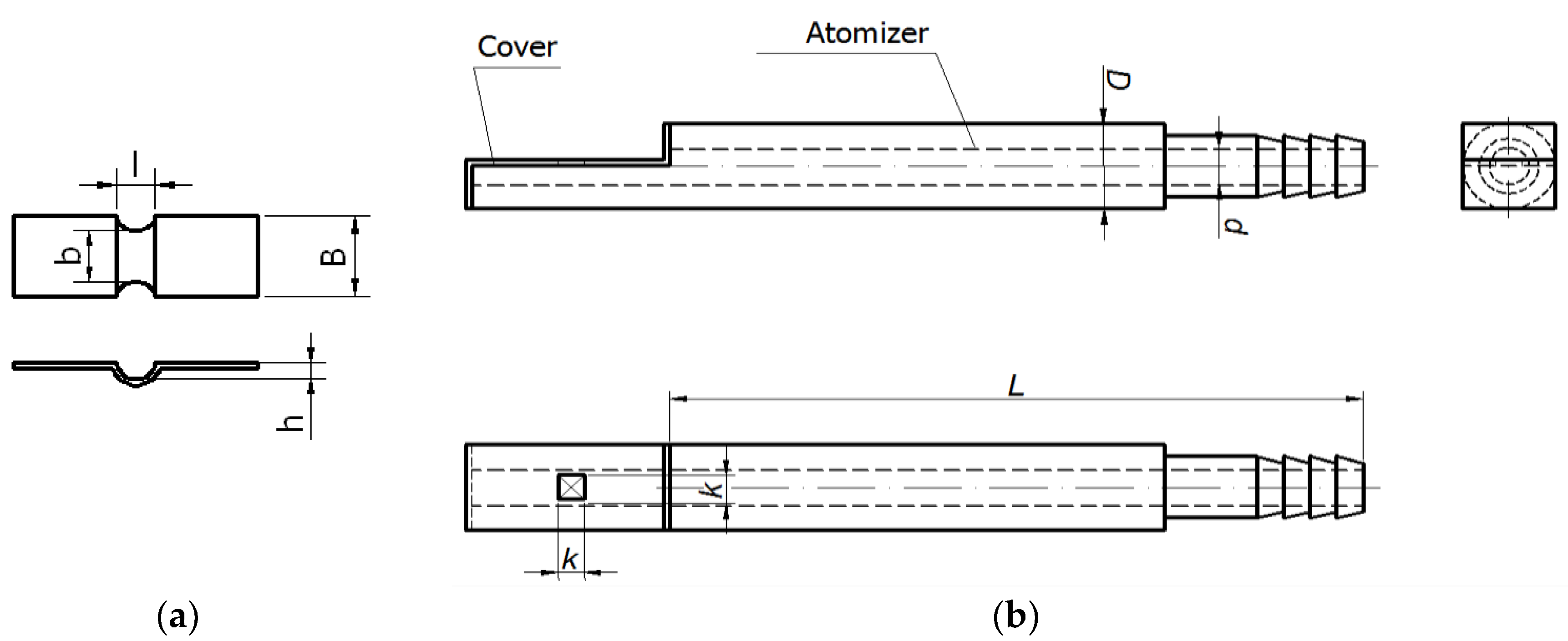
During the experiments, special atomizers of three modifications were tested: with diameters of 12 mm, 14 mm, and 16 mm. The main detail that influences the spraying characteristics of special atomizers is namely the inner shield (Figure 3a), which resolves the integral stream of water into two frontal streams, and when they confront, they form fine spraying. This detail was glued at the cap near the opening (Figure 3).
As the aim is to establish what combination of the parameters ensures good spraying, the outer bodies of the atomizers of various parameters were manufactured, as Figure 3b shows. The inner shield that is demonstrated in Figure 3a was mounted at the cap with the help of glue, as presented in Figure 3b. These bodies were manufactured of brass bars.
During the performance of the experiments, the following parameters were changed (Figure 3): B—width of the inner shield, b—width of the channel, l—length of the channel, h—depth (height) of the channel. The length of the inner plates was 20–25 mm; however, it is not marked, because it does not affect the characteristic of spraying. The following additional parameters are demonstrated by the scheme (Figure 3b): L—length of the body of the special atomizer, k—width of the chamber of the outer cap, d—inner diameter of the atomizer, D—outer diameter of the atomizer.
Table 1 presents the values of the modification parameters of all the special atomizers that were tested.

3. Results and Discussion

3.1. Special Atomizer: Modification No. 1

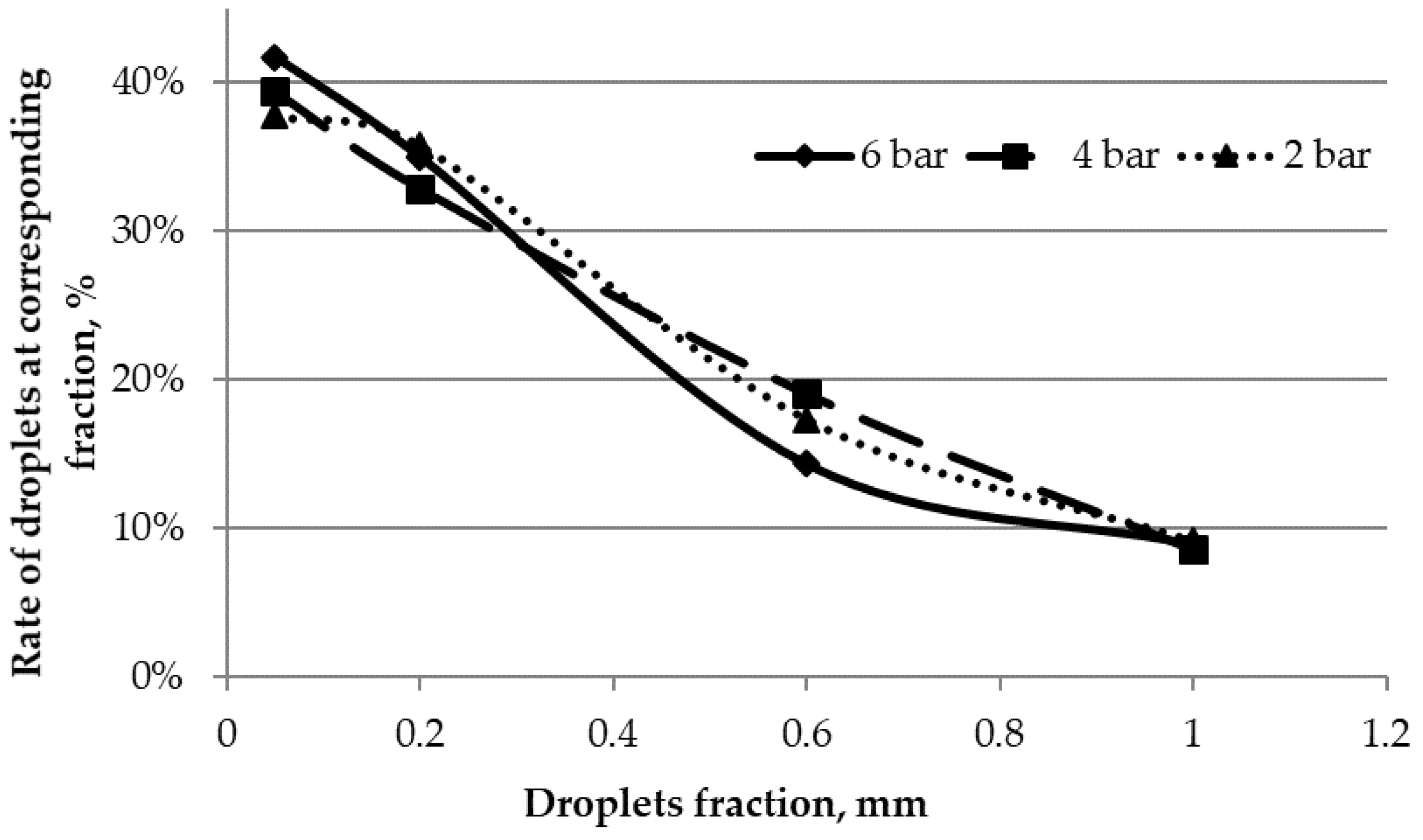
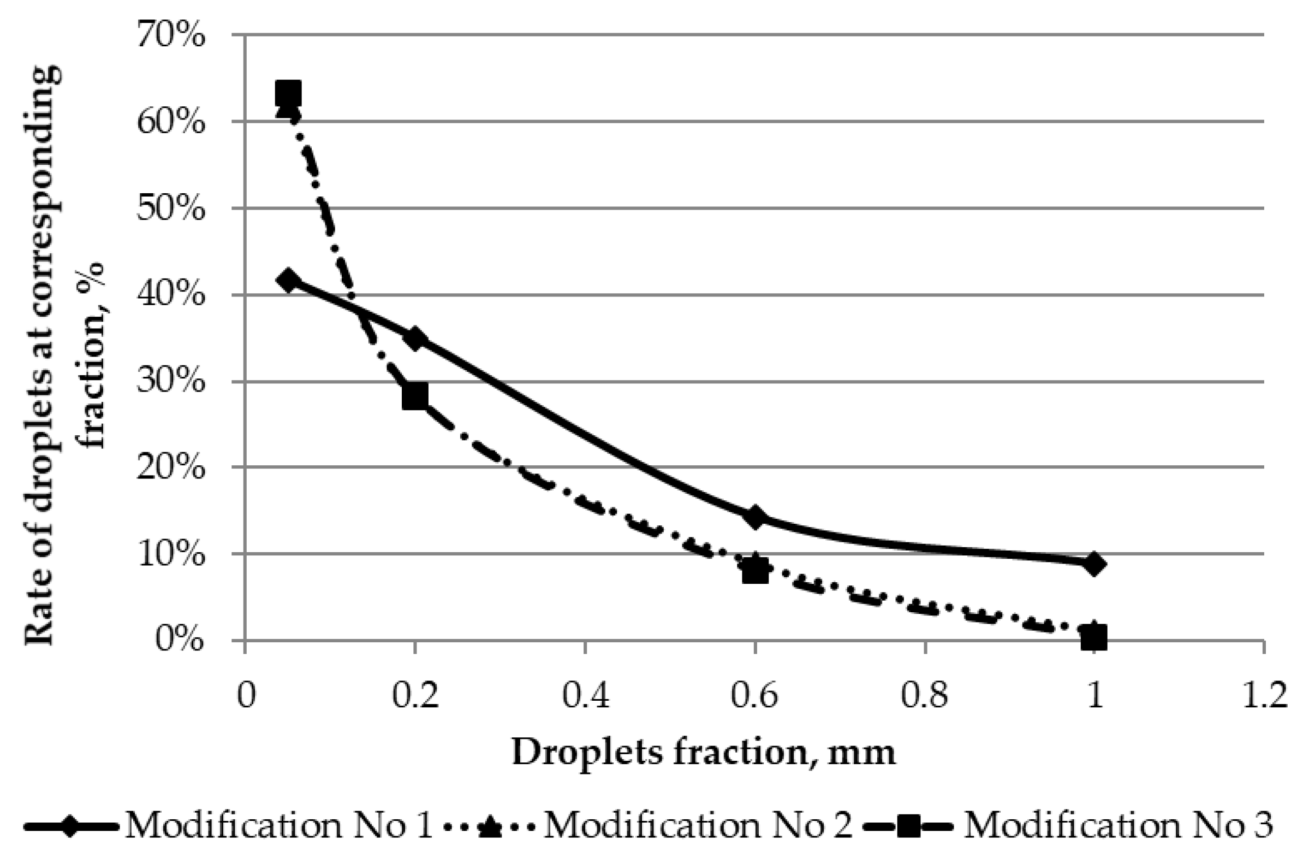
Table 1 presents the parameters of this modification of the special atomizer. Spraying results were achieved under different pressures (namely 6 bar, 4 bar, and 2 bar). It was observed that on average, 41.7 vol% of the sprayed droplets under the pressure of 6 bar are of fine dispersion: 0.05 mm in diameter and smaller. Droplets between 0.05–0.2 mm have formed 1/3 of the sprayed droplets. More massive droplets the size (diameter) of 0.2–0.6 mm have formed 14.3 vol% of the number of the droplets. The most hefty droplets (≥1.0 mm) form at most 9 vol% of the total number of droplets, but it is necessary to consider the fact that the area of the surface that is covered with these droplets is the biggest. Therefore, although they are few, they cover a comparatively large area of the surface. Figure 4 presents the dependence of frequencies on the size of the droplets under the conditions of different pressure. Figure 5 represents the spraying results under the pressure of 6 bar. The view of the small square that is located at the center is represented by part a of Figure 5. It becomes evident that spraying has succeeded in being fine there, but with some large droplets, that might appear because of the merging of some fine droplets. In parts b and c of Figure 5, the spraying is somewhat hefty, because there are more droplets of moderate size (0.2–0.6 mm).
It is evident from the results that on average, 39.4 vol% of the sprayed droplets under the pressure of 4 bar are of fine dispersion: of 0.05-mm diameter and less. The droplets with diameters between 0.05–0.2 mm have formed a part similar to that of the fine ones, i.e., 32.9 vol%. Droplets of moderate size between 0.2–0.6 mm (diameter) have formed 19.1 vol% of the number of droplets. The most hefty droplets (diameter ≥1.0 mm) form 8.6 vol% of the total number of droplets.
It is evident that on average, 37.7 vol% of the sprayed droplets under the pressure of 2 bar are of fine dispersion: 0.05-mm diameter and less. The droplets between 0.05–0.2 mm have formed a part similar to that of fine ones, i.e. 35.8 vol%. The droplets of moderate size between 0.2–0.6 mm (diameter) have formed 17.3 vol% of the number of droplets. The most hefty droplets (≥1.0 mm) form 9.2 vol% of the total number of the droplets, but it is necessary to consider that the area of the surface that is covered with these droplets is the biggest; therefore, although they are few, they cover a comparatively large area of the surface.
It is seen from Figure 4 provided above that the finest spraying with special atomizer (modification No. 1), although not vividly pronounced, was under the conditions of the highest pressure, i.e., at pressure of 6 bar. Then, the amount of the finest droplets was approximately 42 vol%; meanwhile under the conditions of the lesser pressures, it was 39 vol% and 38 vol%, respectively. Although the part of the biggest droplets (size of ≥1.0 mm) under the conditions of the different pressure was mostly the same and equal to 9 vol%, the droplets of the size of 0.6 mm were of 5 vol%.

3.2. Special Atomizer: Modification No 2

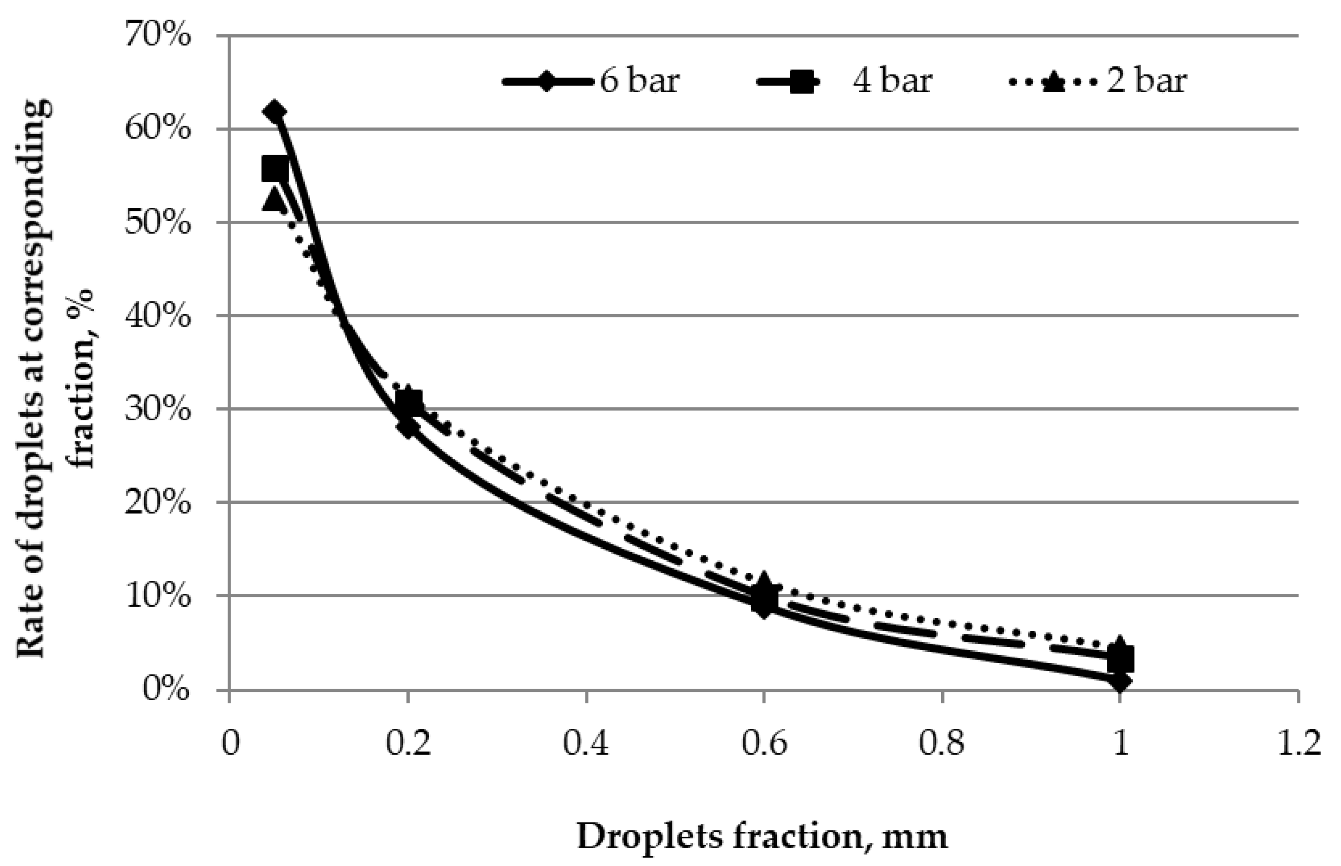
Table 1 represents the parameters of this modification of the special atomizer. It is evident from the results that on the average, 61.9 vol% of the sprayed droplets under the pressure of 6 bar are of fine dispersion: with diameters of 0.05 mm and less. The droplets the size of 0.05–0.2 mm have formed 1/3 of the sprayed droplets. More massive droplets with diameters between 0.2–0.6 mm have formed 8.9 vol% of the number of the droplets. The most hefty droplets (≥1.0 mm diameter) form at most 1 vol% of the total number of the droplets, but it is necessary to consider that the area of the surface that is covered with these droplets is the biggest; therefore, although they are few, they cover a comparatively large area of the surface. Further, the results are represented in Figure 6, i.e., the dependence of frequencies on the size of the droplets under the conditions of different pressure.
As seen in Figure 6, the results show that on average, 55.9 vol% of the sprayed droplets under the pressure of 4 bar are of fine dispersion: with diameters of 0.05 mm and less. Droplets between 0.05–0.2 mm formed a smaller part than the fine ones, i.e., 30.8 vol%. The droplets of moderate size of 0.2–0.6 mm (diameter) formed 9.9 vol% of the number of droplets. The most hefty droplets (≥1.0 mm) formed only 3.4 vol% of the total amount of the droplets.
It is evident in Figure 6 represented above that on average, 52.6 vol% of the sprayed droplets under the pressure of 2 bar are of fine dispersion: of 0.05-mm diameter and less. The droplets with diameters between 0.05–0.2 mm have formed a smaller part than the fine ones, i.e., 31.4 vol%. The droplets of moderate size (diameter) of 0.2–0.6 mm have formed 11.5 vol% of the number of droplets. The most hefty droplets (≥1.0 mm) form 4.5 vol% of the total number of the droplets, but it is necessary to consider that the area of the surface covered with these droplets is the biggest; therefore, although they are few, they cover a comparatively large surface area.
It is seen from Figure 6 provided above that the finest spraying with a special atomizer (modification No. 2), although not vividly pronounced, was under the conditions of the highest pressure, i.e., at a pressure of 6 bar. Then, the amount of the finest droplets was approximately 63 vol%; meanwhile, under the conditions of the lesser pressures, it was 55 vol% and 52 vol%, respectively. The portion made up of the biggest droplets (size of ≥1.0 mm) under the conditions of the different pressure was mostly the same, and equal to about 3 vol%.

3.3. Special Atomizer: Modification No 3

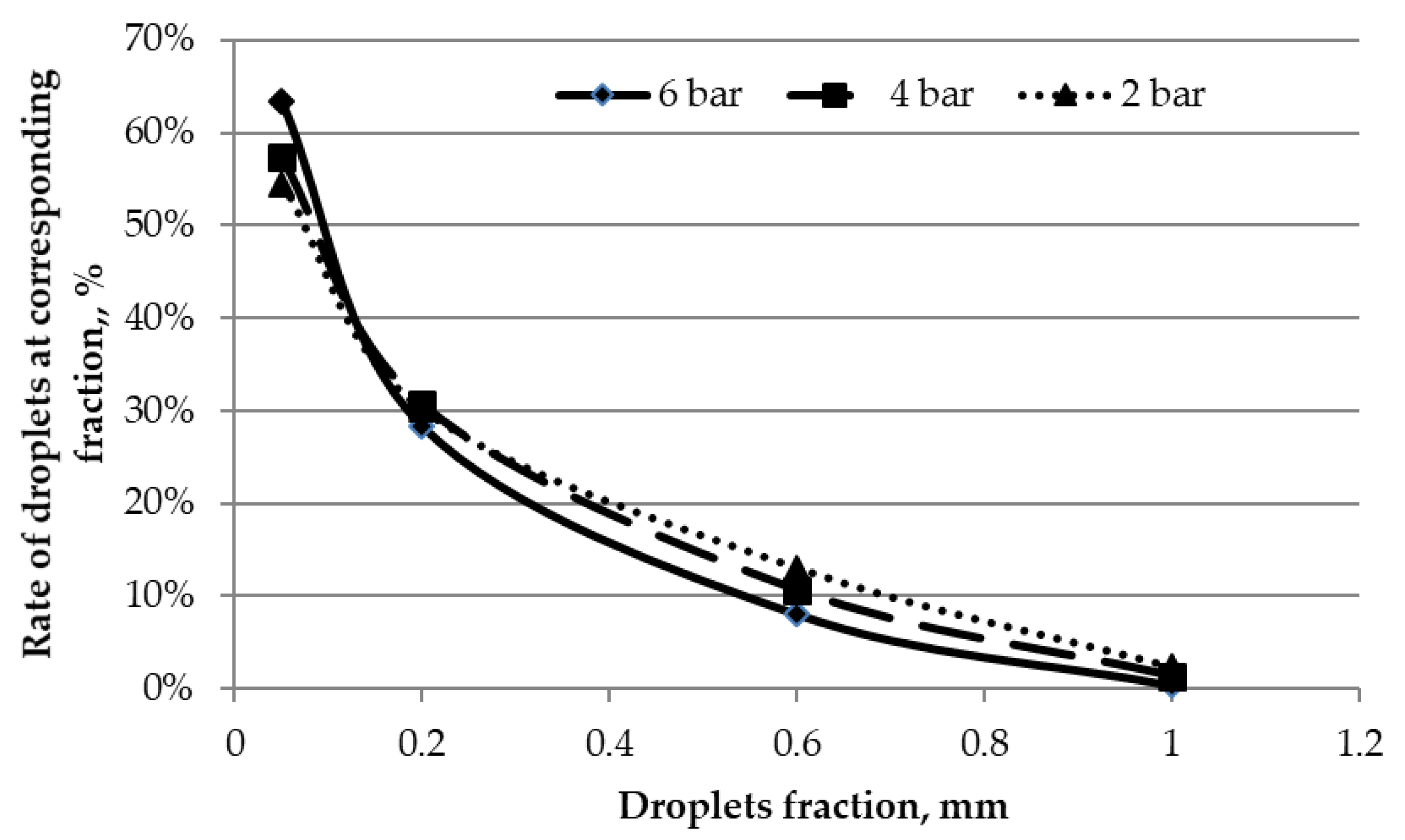
Table 1 represents the parameters of this modification of the special atomizer. Further, the results are represented in Figure 7, i.e., the dependence of frequencies on the size of the droplets under the conditions of different pressure.
It is evident from the results that on average, 63.2 vol% of the sprayed droplets under the pressure of 6 bar are of fine dispersion, of diameters of 0.05 mm and less. The droplets the size of 0.05–0.2 mm have formed approximately 1/3 of all the sprayed droplets. More massive droplets with diameters between 0.2–0.6 mm have formed 8.1 vol% of the number of the droplets. The most hefty droplets (≥1.0 mm) form only 0.4 vol% of the total number of the droplets.
As seen in Figure 7, the results show that on average, 57.3 vol% of the sprayed droplets under the pressure of 4 bar are of fine dispersion, with diameters of 0.05 mm and less. The droplets between 0.05–0.2 mm formed a smaller part than the fine ones, i.e., 30.7 vol%. The droplets with moderate-size diameters between 0.2–0.6 mm formed 10.7 vol% of the number of the droplets. The most hefty droplets (≥1.0 mm) formed only 1.4vol% of the total number of the droplets.
It is evident from Figure 7 above that on average, 54.5 vol% of the sprayed droplets under the pressure of 2 bar are of fine dispersion, with diameters of 0.05 mm and less. Droplets with diameters between 0.05–0.2 mm formed a smaller part than the fine ones, i.e., 30.1 vol%. Droplets of moderate size (diameter) between 0.2–0.6 mm have formed 13.0 vol% of the number of droplets. The most hefty droplets (≥1.0 mm) form 2.3 vol% of the total of the droplets, but it is necessary to consider that the area of the surface that is covered by these droplets is the biggest; therefore, although they are few, they cover a comparatively large area of the surface.
It is seen from Figure 7 provided above that the finest spraying with a special atomizer (modification No. 3), although not vividly pronounced, was under the conditions of the highest pressure, i.e., at a pressure of 6 bar. Then, the amount of the finest droplets was approximately 63 vol%; meanwhile, under the conditions of the lesser pressures, it was 58 vol% and 54 vol%, respectively. The part of the biggest droplets (size ≥1.0 mm) under the conditions of different pressure was mostly the same and equal to about 2 vol%.

3.4. Comparison of the Results Using Different Modifications

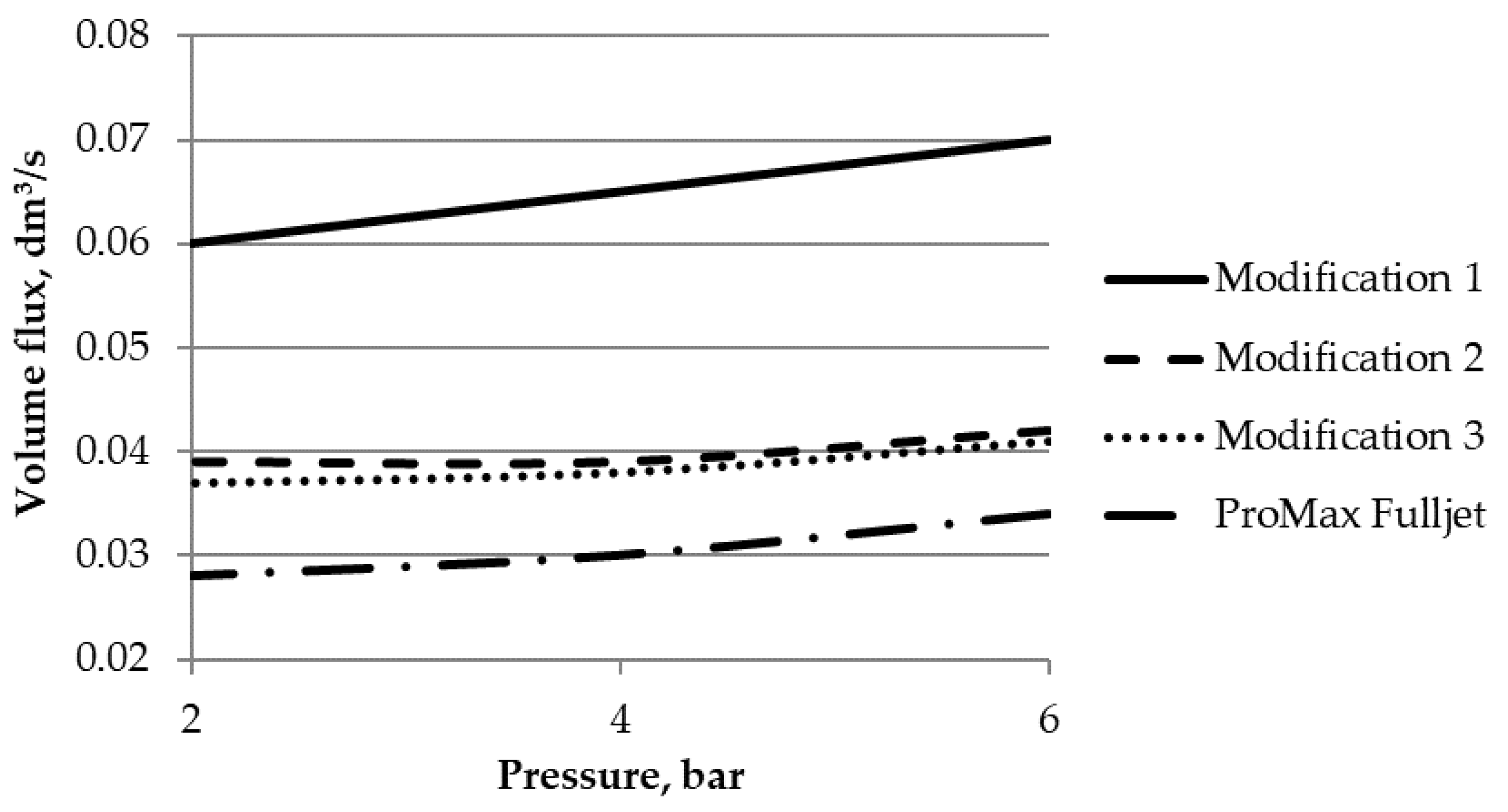
The relationships of volume flux of atomized liquid (in this case, water) versus atomization pressure, taking into account different modifications of atomizers, are represented in Figure 8. An increase in atomization pressure results in an increase in the volume flux of atomized liquid. The atomizer of modification 1 showed the highest volume flux due to its biggest depth of channel (parameter h).
Droplet spectrum classification according to ASAE Standard S572 is shown in Table 2 below, and was used to classify the droplet size. Based on the results, the droplet size varied from fine (141 µm) atomized with a modification 3 nozzle to coarse (300 µm), atomized with a modification 1 atomizer.
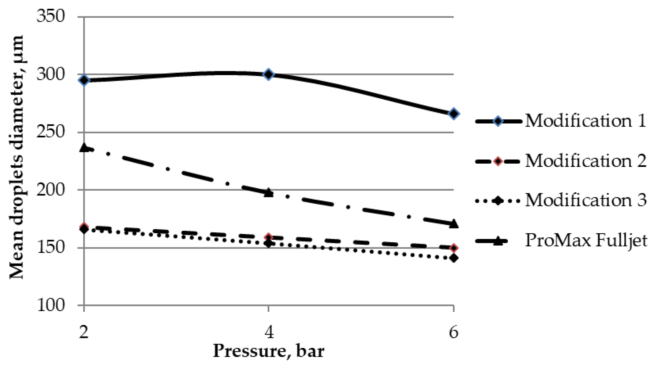
The relationship of the mean diameter of droplets for an atomization spectrum and applied atomization pressure is shown in Figure 9.
As seen in Figure 9, the atomization pressure and mean droplets diameter have the opposite dependency—the higher the pressure is, the finer the droplets that are atomized (sprayed). The finest atomization was performed by the atomizer of modification 3, for which the mean diameter varies from 141 µm to 166 µm at atomization pressures of 6 bar and 2 bar, respectively. A similar diameter (around 150 µm) of the droplets was observed by Rajan and Pandit [36] when a piezoelectric ultrasonic atomizer was used. In comparison to a pneumatic ultrasonic gas atomizer (diameter of around 50 µm) [37], the formed droplets are bigger, but the price of the ultrasonic gas atomizer device is higher.
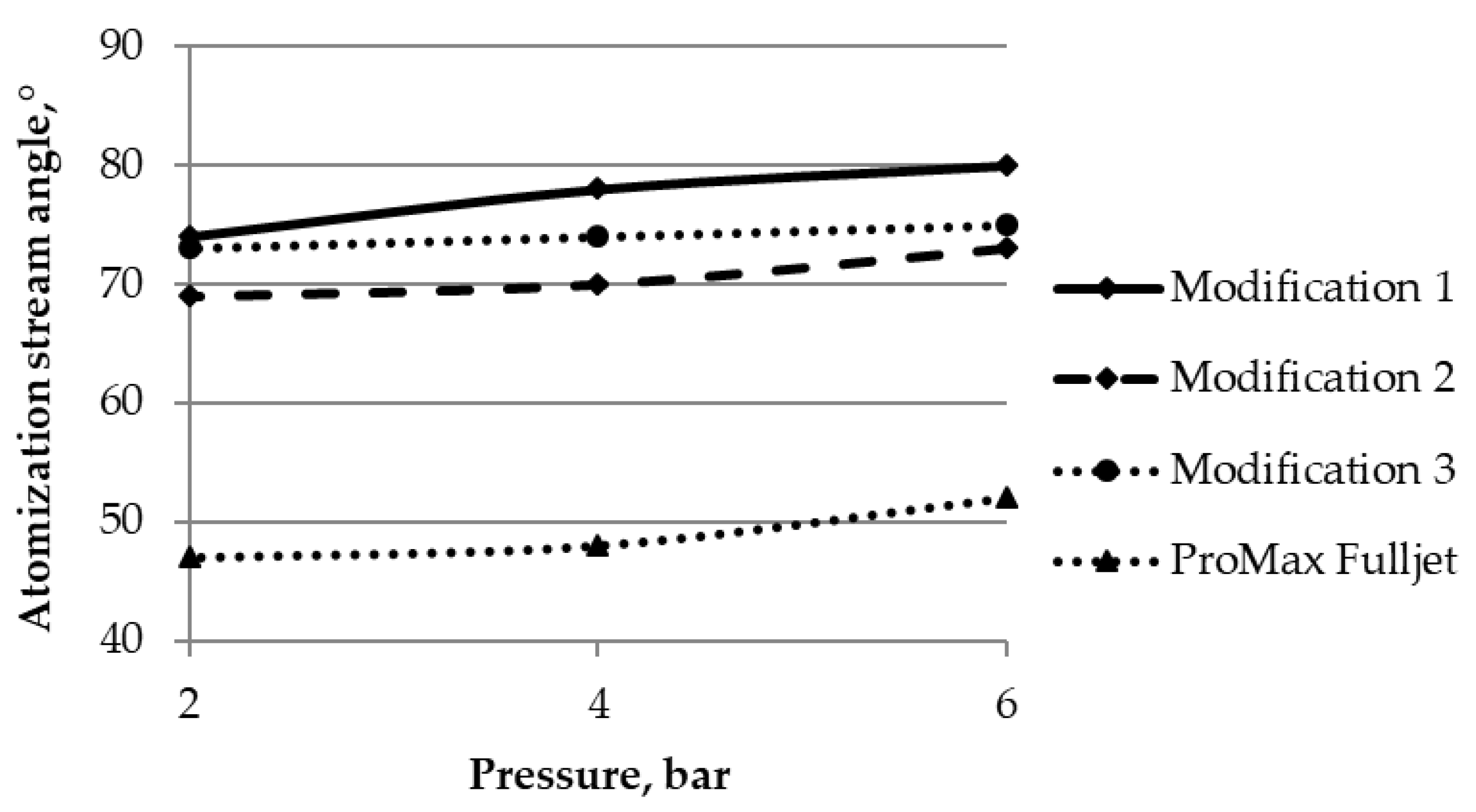
The relationship of the stream angle of atomized liquid (atomization cone) versus the atomization pressure is shown in Figure 10.
As seen from Figure 10, the atomization pressure has an influence on the stream angle. These parameters have positive correlation—increasing atomization pressure causes the increase in the atomized stream angle. The widest stream angle (80 degrees) atomization was observed when using the atomizer of modification 1 at the highest pressure (6 bar). It can be explained by the biggest depth of the channel (parameter h), causing the highest throughput at the highest pressure. It is evident that the finest droplets have formed under the conditions of the utmost pressure, namely 6 bar (Figure 11).
It is evident that the atomizer of modification No. 1 with the depth of the inner shield of 2.6 mm has performed the worst, because the best spraying was reached with the special atomizer of modification No. 3, i.e., with the depth of the channel of the inner shield at 1.4 mm (see h in Figure 3). In the process of spraying with such a special atomizer of such modification, large droplets (of ≥1.0 mm) were formed the least, namely 0.4 vol%. Droplets of the moderate sizes of 0.2–0.6 mm and 0.6–1.0 mm were formed proportionately, namely 28.3 vol% and 8.1 vol%. Such a result is highly similar to spraying with the special atomizer of modification No. 2, but it is still the best, because the droplets of the biggest diameter were formed the least.
While spraying during the experiment, the finest droplets, the size of which was 0.05 mm and less, formed predominantly in the case of all the tested modifications of the special atomizer and also in case of the standard atomizer, namely 63.2 vol%. It is namely because the biggest droplets formed the least, and on the contrary, the finest droplets were predominantly formed, and the spraying, which was performed with the special atomizer of modification 3, is the best of the compared modifications.
Coarser droplets (200–300 µm) produced by atomizers of modifications 1 or 2 may be beneficial for the purpose of flue gas scrubbing due to the slower evaporation of such droplets [38]. Finer droplets (about 50 µm) that are produced in higher portions by the atomizer of modification 3 are better for moistening the substrate in the biofilter. In both the cases of application, the savings of water can be achieved due to smaller water losses.

4. Conclusions

  • The maximal influence on the spraying characteristics of the atomizers of the frontal streams is created namely by the depth of the channel of the inner shield. What strength the frontal streams will confront and what the size of sprayed droplets will be depends on the depth of this channel.
  • The size of only 4 vol% of the droplets, which were sprayed with the special atomizer of modification 3, was 1.0 mm and more. The sizes of the sprayed droplets mainly varied from 0.05 mm to 1.0 mm. These sizes result in the intervals of actual sizes of the droplets that were determined by Schick in 2008, namely 500–5500 µm, and their minimum (0.05 mm) does not reach the beginning of the interval. For this reason, it can be stated that spraying with the special atomizer has been proven to be effective.
  • The spraying characteristics of the hydraulic atomizers depend on the pressure, i.e., the higher the pressure was, the finer droplets that were atomized (sprayed). It is exactly for this reason that the spraying characteristics of atomizers of different structure and different modifications are compared under the conditions of the utmost pressure, as well as under the conditions of the best characteristics of spraying.
  • The tested special atomizers might be applied for watering of the charges of biofilters or for absorbing gases/dust in physical scrubbers. Coarser droplets (200–300 µm) produced by atomizers of modifications 1 or 2 may be beneficial for the purpose of flue gas scrubbing due to the slower evaporation of such droplets. Finer droplets (about 50 µm) that are produced in higher portions by the atomizer of modification 3 are better for moistening the substrate in the biofilter. In both the cases of application, the savings of water can be achieved due to smaller water losses. In the case of application in a biofilter, the less water usage is associated with the lower resistance generated by the less saturated substrate. In both the cases, the efficiency of treatment is achieved. Lower use and greater savings of water contribute to resource savings, which is an important indicator of sustainable development.

Author Contributions

Conceptualization, P.B.; Funding acquisition, P.B.; Investigation, E.B.-G.; Methodology, P.B.; Project administration, P.B.; Resources, P.B.; Supervision, P.B.; Visualization, E.B.-G; Writing – original draft, E.B.-G.

Funding

This research received no external funding.

Acknowledgments

The authors thank Justas Burokas for obtaining the experimental data.

Conflicts of Interest

The authors declare no conflict of interest.

References

  1. Pushnov, A.; Berengarten, M. Ecological aspects of industrial cooling towers exploitation and it’s influence to environment. J. Environ. Eng. Landsc. Manag. 2011, 19, 158–166. [Google Scholar] [CrossRef]
  2. Bravo, D.; Ferrero, P.; Penya-roja, J.M.; Álvarez-Hornos, F.J.; Gabaldón, C. Control of VOCs from printing press air emissions by anaerobic bioscrubber: Performance and microbial community of an on-site pilot unit. J. Environ. Manag. 2017, 197, 287–295. [Google Scholar] [CrossRef] [PubMed] [Green Version]
  3. Dobslaw, D.; Schulz, A.; Helbich, S.; Dobslaw, C.; Engesser, K.-H. VOC removal and odor abatement by a low-cost plasma enhanced biotrickling filter process. J. Environ. Chem. Eng. 2017, 5, 5501–5511. [Google Scholar] [CrossRef]
  4. Ménard, C.; Ramirez, A.A.; Nikiema, J.; Heitz, M. Effect of trace gases, toluene and chlorobenzene, on methane biofiltration: An experimental study. Chem. Eng. J. 2012, 204–206, 8–15. [Google Scholar]
  5. Dobslaw, D.; Schöller, J.; Krivak, D.; Helbich, S.; Engesser, K.-H. Performance of different biological waste air purification processes in treatment of a waste gas mix containing tert-butyl alcohol and acetone: A comparative study. Chem. Eng. J. 2019, 355, 572–585. [Google Scholar] [CrossRef]
  6. Koutinas, M.; Peeva, L.G.; Livingston, A.G. An attempt to compare the performance of bioscrubbers and biotrickling filters for degradation of ethyl acetate in gas stream. J. Chem. Technol. Biotechnol. 2005, 80, 1252–1260. [Google Scholar] [CrossRef]
  7. Dobslaw, D.; Woiski, C.; Winkler, F.; Engesser, K.-H.; Dobslaw, C. Prevention of clogging in a polyurethane foam packed biotrickling filter treating emissions of 2-butoxyethanol. J. Clean. Prod. 2018, 200, 609–621. [Google Scholar] [CrossRef]
  8. Schifftner, C.K. Air Pollution Control Equipment Selection Guide; CRC Press: Boca Raton, FL, USA, 2002; p. 248. [Google Scholar]
  9. Munson, B.R.; Young, F.D.; Okiishi, H.T.V. Fundamentals of Fluid Mechanics, 5th ed.; Wiley: New York, NY, USA, 2006; p. 766. [Google Scholar]
  10. Faeth, G.M.; Hsiang, L.P.; Wu, P.K. Structure and break-up properties of spray. Int. J. Multiph. Flow 1995, 21, 99–127. [Google Scholar] [CrossRef]
  11. Kärrholm, F.P. Numerical Modelling of Diesel Spray Injection Turbulence Interaction and Combustion. Ph.D. Thesis, Chalmers University of Technology, Gothenburg, Sweden, 28 November 2008; p. 86. [Google Scholar]
  12. Schick, J.R. Spray Technology Reference Guide: Understanding Drop Size; Bulletin 459C; Spraying Systems Co.: Wheaton, IL, USA, 2008; p. 35. [Google Scholar]
  13. Liu, H. Science and Engineering of Droplets: Fundamentals and Applications; William Andrew Publishing: New York, NY, USA, 2000; p. 539. [Google Scholar]
  14. Datta, A.; Som, S.K. Numerical prediction of air core diameter, coefficient of discharge and spray conce angle of a swirl pressure nozzle. Int. J. Heat Fluid Flow 2000, 21, 412–419. [Google Scholar] [CrossRef]
  15. Patel, R.P.; Patel, M.P.; Suthar, A.M. Spray drying technology: An overview. Indian J. Sci. Technol. 2009, 2, 44–47. [Google Scholar]
  16. Bayvel, L.; Orzechowski, Z. Liquid Atomisation; Taylor & Francis Publ.: Washington, DC, USA, 1993; p. 462. [Google Scholar]
  17. Michelson, D. Electrostatic Atomisation; Adam Hilgier: New York, NY, USA, 2000; p. 164. [Google Scholar]
  18. Lohmann, M. Herstellung von Partikeln durch elektrostatische Zerstäubung von Flüssigmetallen in gasförmiger Umgebung. Ph.D. Thesis, Universität Duisburg, Duisburg, Germany, January 2001. [Google Scholar]
  19. Armster, S.Q.; Delplanque, J.P.; Rein, M.; Lavernia, E.J. Thermo-fluid mechanisms controlling droplet based materials processes. Int. Mater. Rev. 2002, 47, 265–301. [Google Scholar] [CrossRef]
  20. Spellman, F.R.; Whiting, N.E. Environmental Engineer’s Mathematics Handbook; CRC Press: Boca Raton, FL, USA, 2004; p. 664. [Google Scholar]
  21. Wang, L.K.; Pereira, N.C.; Hung, Y.T. Biological treatment processes. In Handbook of Environmental Engineering; Humana Press: New York, NY, USA, 2009; p. 818. [Google Scholar]
  22. Mondal, D.; Datta, A.; Sarkar, A. Prediction of drop size distribution in a spray from a pressure swirl atomiser using maximum entropy formalism. Proc. Inst. Mech. Eng. Part C J. Mech. Eng. Sci. 2003, 217, 831–838. [Google Scholar] [CrossRef]
  23. Doll, D.A.; Sojka, P.A.; Hallet, G.S. Microsphaeropsis amaranthi. Weed Technol. 2005, 19, 918–923. [Google Scholar] [CrossRef]
  24. Okita, Y.; Nakamura, K.; Nishimoto, K.; Yanasaka, N. Performance of Abrasive suspension jet nozzles with a singular annular conduit. In Proceedings of the 6th Pacific Rim International Conference on Water Jetting Technology, Sidney, Australia, 9–11 October 2000; pp. 111–114. [Google Scholar]
  25. Barber, J. How to Pre-empt a Significant Profit Drain: Atomiser Wear; Spraying Systems Co.: Wheaton, IL, USA, 2009; p. 6. [Google Scholar]
  26. Kutz, M. Handbook of Environmental Degradation of Materials; William Andrew Publishing: Boca Raton, FL, USA, 2005; p. 571. [Google Scholar]
  27. Wang, L.K.; Hung, Y.T.; Shammas, N.K. Advanced Physicochemical Treatment Processes. In Handbook of Environmental Engineering; Humana Press: New York, NY, USA, 2006; p. 45. [Google Scholar]
  28. Harrop, O.D. Air Quality Assessment and Management: A Practical Guide; Spon Press: London, UK, 2001; p. 281. [Google Scholar]
  29. Kemzuraite, A.; Raila, A.; Bimbiraite, K.; Kornysova, V.; Maniska, A. Moisture dynamics modelling in Hyssopi Herba drying process by active ventilation. J. Environ. Eng. Landsc. Manag. 2009, 17, 36. [Google Scholar]
  30. Cieciura-Włoch, W.; Borowski, S. Biohydrogen production from wastes of plant and animal origin via dark fermentation. J. Environ. Eng. Landsc. Manag. 2019, 27, 101–113. [Google Scholar]
  31. Aikaite-Stanaitiene, J.; Grigiskis, S.; Levisauskas, D.; Cipinyte, V.; Baskys, E.; Kackyte, V. Development of fatty waste composting technology using bacterial preparation with lipolytic activity. J. Environ. Eng. Landsc. Manag. 2010, 18, 296–305. [Google Scholar] [CrossRef]
  32. Pawłowska, M.; Zdeb, M.; Montusiewicz, A.; Lebiocka, M. Decomposition of hydrogen sulfide in organic materials. Environ. Prot. Eng. 2009, 35, 157–165. [Google Scholar]
  33. Abd-Elsalam, K.A.; Bahkali, A.H.; Moslem, M.A.; Al-Hazzani, A.A.; Amin, O.E.; Al-Khedhairy, A. Freeze- and thaw-based procedures for extracting DNA from activated sludge. Pol. J. Environ. Stud. 2011, 20, 643–648. [Google Scholar]
  34. Przybulewska, K.; Wieczorek, A. Biodegradation of methyl isobutyl ketone (MIBK) by Fusarium solani. Arch. Environ. Prot. 2009, 35, 3. [Google Scholar]
  35. Kierzkowska-Pawlak, H.; Chacuk, A. Kinetics of carbon dioxide absorption into aqueous MDEA solutions. Ecol. Chem. Eng. S 2010, 17, 463–475. [Google Scholar]
  36. Rajan, R.; Pandit, A.B. Correlations to predict droplet size in ultrasonic atomisation. Ultrasonics 2001, 39, 235–255. [Google Scholar] [CrossRef]
  37. Kim, K.D.; Jin, D.H.; Choi, Y.C. Numerical simulation on the generation of ultrasound and formation of water fog in the ultrasonic gas atomiser. Ultrasonics 2018. [Google Scholar] [CrossRef]
  38. Marchiewicz, A.; Sobczyk, A.T.; Krupa, A.; Jaworek, A. Induction charging of water spray produced by pressure atomiser. Int. J. Heat Mass Transf. 2019, 135, 631–648. [Google Scholar] [CrossRef]
Figure 1. Scheme of the experiment: 1—the arm of the water supply system; 2—fenestrated hose; 3—manometer; 4—manual valve; 5—experimental atomizer; 6—atomization (spraying); 7—the affected surface.
Sustainability 11 05522 g001
Figure 2. Positions of sheets (sizes in cm).
Sustainability 11 05522 g002
Figure 3. Scheme of the special atomizer inner shield (a) and the body and cap (b).
Sustainability 11 05522 g003
Figure 4. Efficiency of spraying under different pressure, modification No 1.
Sustainability 11 05522 g004
Figure 5. Sprayed droplets (modification No. 1, pressure—6 bar) (a) at the center of the sheet; (b) at periphery of the sheet, 25 cm from the center; (c) at periphery of the sheet, 35 cm from the center.
Sustainability 11 05522 g005
Figure 6. Efficiency of spraying under different pressures, modification No 2.
Sustainability 11 05522 g006
Figure 7. Efficiency of spraying under different pressures, modification No. 3.
Sustainability 11 05522 g007
Figure 8. Volume flux of atomized liquid versus atomization pressure.
Sustainability 11 05522 g008
Figure 9. Relationship of the mean diameter of droplets and applied atomization pressure.
Sustainability 11 05522 g009
Figure 10. Relationship of the atomization stream angle and applied atomization pressure.
Sustainability 11 05522 g010
Figure 11. Spraying efficiency of different modifications of atomizers.
Sustainability 11 05522 g011
Table 1. Parameters of special atomizers of different kinds.
No.Parameters, mm
lBbhdDLk
14.07.07.02.76.016.0135.04.0
23.46.84.51.66.014.0135.04.0
33.26.74.31.46.012.0135.04.0
Table 2. Droplets spectrum classification.
Atomizer TypePressure, barMean Droplet Diameter, µmASAE (American Society of Agricultural Engineers) Standard
SymbolCategoryCodeApx. MD
Modification 16266CCoarseBlue250–375
4300
2295
Modification 26150MMediumYellow175–250
4159
2168
Modification 36141FFineOrange100–175
4154
2166
ProMax Fulljet6171MMediumYellow175–250
4198
2237