Abstract
This paper will present a new concept of cable cars with central entry and exit. First, existing systems of cable cars and their properties will be presented and advantages of the new concept will be explained. The new concept utilizes solution geometry as the basis of the idea. 3D computer graphic tools were used for the design. In the second part of the article, the geometric procedure of the design of the rope flow curve in the station is presented. This is necessary in order to stop the cabin steadily in the central position. If the station is designed in such a way that passengers enter and exit on a stationary platform separate from the device, the capacities of the device can be large. In this case, passengers entering and exiting do not interfere with the other passengers who are traveling with the cable car on the line.
1. Introduction
Transportation with cable cars can be a sustainable public transport in the future. Additionally, cable cars have many advantages such as electric drive and low surface area consumption since transport takes place by air. This can be a sustainable mode of transport, if electricity is derived from renewable energy sources as discussed by D. Gattuso [1].
According to the operating technology, there are two groups of aerial cable cars for transporting passengers: aerial tramways and gondolas [2,3,4].
Aerial tramways use only two cabins, which are on the track [5,6,7]. The maximum speed is 12 m/s or 43.2 km/h. [8]. The main characteristics are [9]:
- -
- they can overcome major gaps and distances, the span between the pylons can be extraordinarily long–more than 1 km;
- -
- the cabins come to a complete stop at each station, in which passengers have enough time to exit and enter;
- -
- they have a small capacity (maximum 2000 passengers per hour, maximum 200 passengers per cabin);
- -
- they can overcome great inclines;
- -
- during ingress and egress the device must be completely stopped;
- -
- the average waiting time of passengers at the station is longer than a gondola due to the entry and exit of cabin (dwell times).
Gondolas are cable cars with unidirectional circulating vehicles–cabins [10]. The speed is slower than aerial tramways, with a maximum of 7 m/s for bicable devices and a maximum of 6 m/s for monocable devices. [8] The main characteristics are [9]:
- -
- carrying up to 30 persons per cabin;
- -
- cabins have greater capacities than aerial cars–up to 4000 (theoretically 6000) passengers per hour;
- -
- wait times are shorter as the cabins are smaller;
- -
- vehicles are on constant rotation, so there is no wait time at stations;
- -
- cabins move slowly through each station, they do not come to a complete stop, causing entry to be possibly difficult for persons with disabilities and older adults;
- -
- there are more cabins per cable, therefore, the spans between each pylon are smaller;
- -
- the time for entering and exiting is limited by the speed of the device and length of the platform.
Chairlifts with fixed grips have a maximum speed through the station of 2.5 m/s (with no transport conveyor at the entrance) [8]. These chairs travel with the same speed as the rope, so the chairs quickly travel through the station and entrance for skiers or passengers is difficult. Depending on the performance, they are very simple and inexpensive.
Gondolas with cabins and chairlifts with detachable grips have reduced speeds through the station 0.5 m/s [8] and entrance for skiers and passengers is easier. The design of the unidirectional gondola with detachable grips is much more expensive, since the station has a conveyor which decelerates, moves, and accelerates the cabins through the station when they are detached from the rope [11]. Therefore, this type of cable car is very expensive (Figure 1).
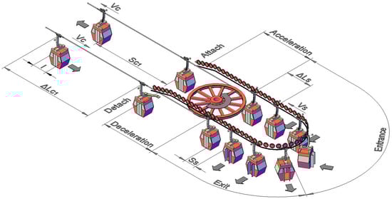
Figure 1.
Existing system of gondolas–passenger entry and exit at station [9].
Both systems have advantages and drawbacks, leading to the question of whether a cableway device could be designed that contains the advantages of both systems:
- -
- the system should have a high capacity containing more vehicles;
- -
- vehicles should stop at the station and, at the same time, the vehicles on the line of the cable car would travel smoothly along the line; this would make entry and exit very easy;
- -
- the design should be simple (without special conveyors to decelerate, accelerate, and move cabins through the station).
The desired properties of the cableway devices can be achieved with a new invention, whereby a special form of attachment of the suspension to the cabin is used in a precisely determined length of the suspension. By using geometric solutions and kinematics, fixed grips for fixings on the rope can be used.
The idea was presented for the first time at the Department of Transportation Engineering (Faculty of Civil Engineering, Transportation Engineering and Architecture) at the University of Maribor on 4 June 2014, where sketches were shown [12].
The solution is presented in the left sketch (a) of Figure 2. The cabin for gondolas is in the middle and the rope with suspension in a horizontal position is rotating around the standing cabin. In this way, passengers can enter and exit the cabin, which is not moving, allowing for its use by people with disabilities.
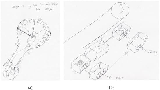
Figure 2.
Sketches demonstrating the basic idea for a cable car system with central entrance and exit in the station (a) and cable cars with separate platforms for entrance and exit for a large number of passengers in the station (b).
The right sketch (b) of Figure 2 demonstrates the solution where people can enter and exit from an extra separate platform which is not connected with the cabin at the station. In this way, passengers have enough time to enter and exit and they do not interfere with other moving cabins on the line. When a vehicle comes into the station, it must attach to this platform with passengers.
2. Methodology
Throughout history, those who wanted to present their ideas or innovations were required to be good painters, so that they could explain their ideas to the rest of the world. Leonardo da Vinci drew his ideas and Fausto Verancio (Faust Vrančič in Croatian), in his book Machinae Novae from 1616, presented the drawing of the first cable car (ropeway) in Europe [13]. Nowadays, other efficient tools can be used for the presentation of ideas, such as computer graphics and 3D modelers.
A geometrical model of a cable car station was developed for this new operating model of cable car that includes a central entrance and exit. This model included elements that affect passenger entry and exit. Virtual space in CAD program with 3D modeling (Autocad) is used in the research environment for the development of the new geometric models.
Based on the above disadvantages of the existing systems, a new proposed model was established. This improved the characteristics for calculating the geometry, capacities, and other properties of the cable cars. A geometric design that included new ideas presented in this paper was implemented within the 3D geometric model.
The issues that arise because of the stopping of the cabin in the station is a geometric problem. It deals with the interaction of cabins, rope, and suspension as geometric elements that change their position over time. The methods used to find the solution is the use of descriptive geometry and kinematics. Using this research methodology, the geometric procedure of design of the “rope flow” curve in the station was established. This curve is necessary to stop the cabin in the central position.
3. Results
One year elapsed from the idea presented in Figure 3 to the construction of the 3D computer model. Through consultation, two variants of the model were developed. The first is a simple and inexpensive cable car implementation for the transport of a small number of passengers and the second is a more complicated version with a higher capacity. For this second version, the geometric procedure of the rope flow curve is established.
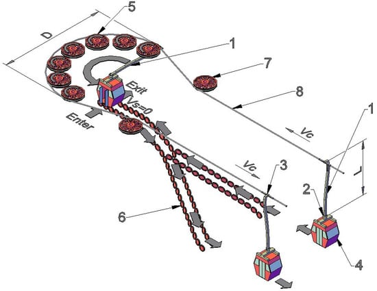
Figure 3.
3D computer model of a cable car with central entrance and exit at a station.
3.1. Model of a Cable Car System with Central Entry and Exit
The model of the cable car system with central entry and exit is presented as a static computer 3D model in Figure 3. A patent application for this kind of cable car was submitted.
3.1.1. Description of the Operation
- Suspension (L–length of suspension)
- Attachment element (connection between cabin and suspension)
- Fixed grip (connection between suspension and rope)
- Cabin
- Drive wheels (or return wheels)
- Supporting wheels
- Deflection wheel
- Carrying/hauling rope
Figure 3 presents a new concept of a unidirectional cable car with central entry and exit, consisting of several cabins. At the station, cabins are completely stopped while other cabins outside move along the track. The construction concept is simple: it uses fixed grips and does not require conveyors for braking, transporting, and accelerating cabins at a station. Only supporting wheels, which are free and do not need extra drive, are needed.
The base for the invention of the circular cable car with central entry and exit is the length of suspension L that connects the cabin and the fixed grip, which is also the distance between the center of the upper part of the cabin and attachment to the rope. The distance L is equal to half of the diameter D of the rotation of the rope at the station. Circulation of the rope at the station is enabled by drive wheels or return wheels (or one big drive wheel or return wheel is sufficient), which form a half circle with diameter D.
L–length of the suspension (m)
D–diameter of the rope rotation in station (m)
The ratio allows a cabin to arrive to station by guiding it to the center of the half circle (around which a carrying/hauling rope moves) with the help of supporting wheels. During this process, the suspension moves from a vertical position to the horizontal position. In this way, the cabin stops in the station while the fixed grip and rope rotates around the drive or return wheels. As the suspension turns around, the cabin is in a central position and allows passengers to exit and enter the cabin.
When the suspension is in an inclined or horizontal position rotated 180° (Figure 4a), the cabin starts to move with the help of the support wheels and leaves the station. The suspension is again placed in the vertical position. This design is possible with a special attachment of the suspension on the cabin which allows for an incline of 90° (from the vertical to the horizontal position) and for the rotation of the suspension in the horizontal position around the cabin (Figure 4b). When the cabin is out of the station (on the track), the incline of the suspension must be disabled.
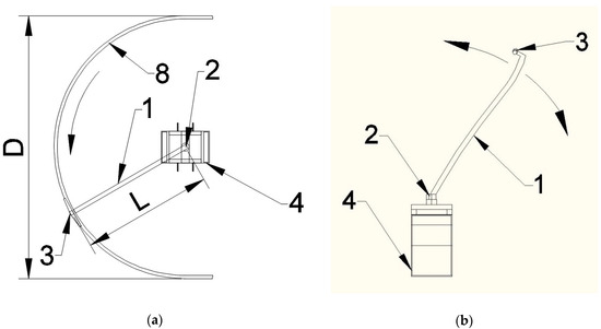
Figure 4.
Ground plan of the station with rotating suspension (a) and front view of the cabin with inclining suspension (b).
With this invention, vehicles can be stopped in the station at circular cableways with fixed grips and passengers can exit or enter smoothly. The implementation of the circular cableway with fixed grips is cheaper than a circular cableway with detachable grips.
3.1.2. Size of Device
Figure 3 and Figure 4 raise the question of the size of the system. If the cabin is for four passengers, six seconds is enough to empty the cabin through the right door and for loading the cabin through the left door. Six seconds is the time the cabin stands in the central position. The velocity of this cable car with fixed grips is 2.5 m/s—like chairlifts with fixed grips. The rope with fixed grip has six seconds to traverse the following length:
-length of path which is made by the rope during the 180° rotation (m)
-speed of the cable car (m/s)
-time cabin is stationary in station - time for entry and exit (s)
is half of the perimeter of the circle and this determines the length of the suspension (L) which is half of a diameter of the circle:
The abovementioned cable car with central entry and exit requires a station that is at least 9.54 m wide. If the cabin in the central position is replaced with the next cabin every eight seconds, then the capacity of the cable car is [9]:
-capacity of the cable car (persons/h)
-interval between cabins (s)
n-number of persons in the cabin (persons)
If we want bigger cable cars with central entry and exit, for instance eight persons in the cabin, then the cabin must stay in the central position for 10 s, the length of suspension (L) would be 7.96 m, and the width of the station should be about 20 m. The capacity with a 12 second interval between cabins will be 2400 persons/hour. The station must double in width for a 33% increase in capacity, so this type of cable car is not suitable for higher speeds and larger cabins. It is suitable for a capacity of up to 1800 persons/hour and for a velocity of up to 3 m/s.
3.2. Model of A Cable Car System with Attaching Platforms in A Central Position
If passengers can enter and exit from special platforms in the station that are detached from the cabin, then the cable car can reach large capacities. The idea is that entry and exit is separate in the stationary platform. When the cabin arrives into the station, it attaches to a platform full of passengers. This kind of device provides passengers with enough time to enter and exit and, at the same time, the vehicles on the line of the cable car would travel smoothly along the line.
- Suspension (L–length of suspension)
- Attachment element (connection between cabin and suspension)
- Fixed grip (connection between suspension and rope)
- Cabin
- Drive wheels (or return wheels)
- Platform
- Deflection wheel
- Carrying/hauling rope
3.2.1. Description of the Operation
Figure 5 is a model of a cable car system where the cabin attaches to a platform when in the central position. The operation is similar to the cable car with central entry and exit. When the cabin enters the station, it moves to the middle of the line at the same time that the rope is guided down so the suspension can come to a horizontal position. This is more comfortable for passengers because the cabin is always on the same level. When the suspension is in the horizontal position, the fixed grip with rope rotates around the curve (it is not circular, but an elliptical curve). With this curve, the cabin in the middle can slow down. First, the platform that came into the station detaches from the cabin. When the platform is detached from the cabin, it moves with a conveyor to the position where can passengers can smoothly exit and enter. When the cabin is stopped at the central position, it can attach to the next platform full of passengers. After attaching to the platform, the cabin accelerates and leaves the station. The special curve of the rope flowing provides deceleration and acceleration for the cabin in the station. This kind of cable car uses fixed grips. If the length of the suspension is 8 m, then the station width must be a minimum of 16 m. When the cabin with attaching platforms leaves the station, the suspension sinks into the platform. In this way, the connection between the cabin and platform is more secure on the line.
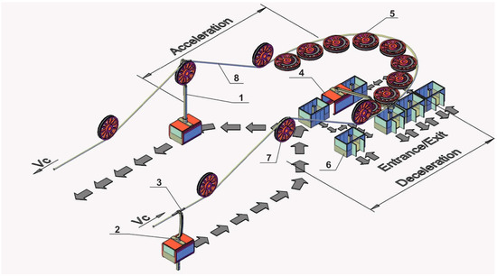
Figure 5.
3D computer model of cable car with attaching platforms in a central position.
If the platforms have a capacity of 100 passengers and every 30 s one platform can be attached to the cabin, then the total capacity of this kind of cable car can reach 12,000 passengers per hour. This type of cable car can have a middle station, because the platform can detach from the ending station of the first line and then moves with a conveyor to the starting station of the second line.
3.2.2. Geometric Procedure of the Design of the “Rope Flow” Curve
This type of cable car decelerates and accelerates the cabins only with the geometric shape of the carrying/hauling rope on which the cabins are connected with fixed grips. Thus, the rope must flow on the special curve which is provided with drive wheels. To get this curve of flowing rope in the station, a geometric procedure for design using descriptive geometry is required. This curve is necessary in order to stop the cabin steadily in the central position.
This shape of curve allows the cabin at the middle of the line in the station to decelerate while the rope and fixed grip move around the curve with constant speed. Constant maximum deceleration or acceleration for cable cars can be 0.5 m/s2 [6]. If the speed of the cable car is 5 m/s and the length of suspension is 8 m, then the procedure for curve design is as follows:
The cabin at the middle position needs 10 s to stop from speed VC = 5 m/s (Figure 6). During the first second, the speed of the cabin falls from 5 m/s to 4.5 m/s. In this first second, the cabin makes the path:
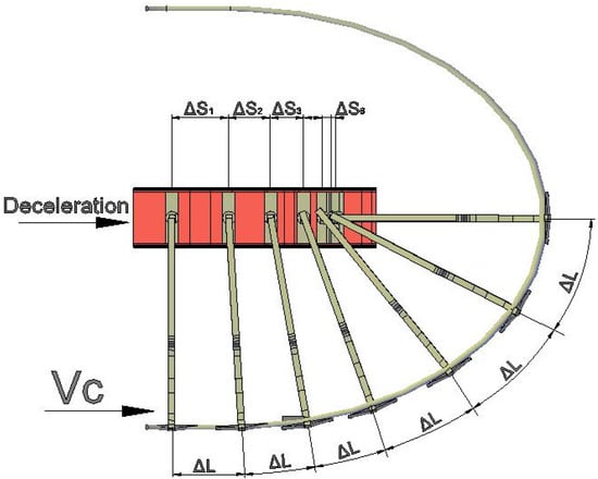
Figure 6.
Basis for the calculation for deceleration of the cabin to the center position.
During the same first second, the rope travels a distance of 5 m (with a speed of 5 m/s)
During second two, the speed of the cabin falls from 4.5 m/s to 4 m/s and travels:
Also, during second two, the rope travels = 5 m (with speed 5 m/s)
During the third second, the speed of the cabin falls from 4 m/s to 3.5 m/s. In this third second, the cabin travels:
During the same third second, the rope travels = 5 m (with speed 5 m/s).
Such calculations can be made for the further seconds of the deceleration of the cabin at the middle of the line. The construction of the curve (Figure 7) begins at the time t = 0, when the cabin begins to decelerate and the velocity of the cabin is 5 m/s. The cabin is at point AO and the fixed grip on the rope is in point DO. The distance between these two points is L = 8 m. This is the length of the suspension. In the first second, from time t = 0 to time t = 1, the cabin travels = 4.75 m, so the distance from AO to A1 is 4.75 m. At the same time, the rope travels = 5 m, so the distance between DO to D1 is 5 m. The intersection between an arc with radius L = 8 m with its center at A1 and an arc with radius = 5 m gives the point D1. From point D1 to point D2 is again = 5 m. From point A1 to A2 is a distance of = 4.25 m. The intersection between an arc with radius L = 8 with its center at A2 and an arc with radius = 5 m gives the point D2. Again, the intersection between an arc with radius L = 8 with its center at A3 and an arc with radius = 5 m gives the point D3. This procedure can be continued, and where the points D connect with lines, we can get the polyline. However, these points can also connect with spline which modern geometric modelers like Autocad have.
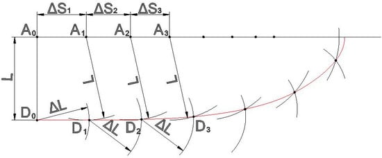
Figure 7.
The construction of the “rope flow” curve for deceleration of the cabin in the station.
When this curve is mirrored over the horizontal line at the middle of the station, we can get the curve for acceleration for the cabins which attach with the platform and both leave the station.
4. Discussion
The cable car with central entry and exit has several advantages and disadvantages.
The advantages of this type of device are the simple and cheap design, and the fact that cabins would stop at the station and, at the same time, the cabins on the line of the cable car would travel smoothly along the line. This would make entry and exit very easy for older and disabled persons. This type of cable car does not need conveyors for decelerating, moving, and accelerating the cabins through the station because these functions are performed by the rope. The price for this type of system is comparable to chairlifts with fixed grips, around 3 million €. As cabins are more expensive than chairs, the price could be potentially between 4 and 5 million €. This is a much cheaper option than the price for a monocable gondola with detachable grips. The price for a gondola with a capacity of 3000 persons/h, with 100 cabins and 20 pylons without intermediate stations, is around US$11 million [9].
The disadvantages of this type of system are a reduced capacity and limited time for passenger entry and exit. The speed of the cable car is slow (2.5 m/s like chairlifts with fixed grips) and cabins must travel up at the station because the suspension has to be in a horizontal position for rotating. A better solution may be that the rope travels down in the station and cabins are at the same level, as in Figure 5 where an advanced type of cable car with similar operation is presented. Cable cars with central entry and exit cannot have middle stations and they need a lot of space for stations.
On the other hand, the cable car with attaching platforms in the central position also does not need conveyors for deceleration, movement, and acceleration of the cabins through the station. When the cabin reaches the middle position it can decelerate with the geometry of the “rope flowing” curve. The advantage of this kind of device is that the platform can separate from the cabin and passengers can exit and enter smoothly while the cable car system continues to operate and transport cabins on the line. However, this system can be very expensive due to moving platforms.
In the case of the further development of the cable car with the stopped cabin in the center of the station, a dynamic virtual model with all moving parts should first be developed before the device is built in the real world.
If the cable car with attaching platforms as a transport system can have a capacity of 12,000 passengers per hour, it can be very competitive with other types of transport in urban environments. There is a possibility for mass transportation of passengers to terminals, by air, where it is otherwise not possible to build other transport systems. It could serve as a crossing for densely populated areas such as hilly terrain or rivers crossings. Additionally, it can provide a connection to city centers with airport terminals or port terminals along rivers. This transport system can be used in multimodal public transport systems [14].
According to the Transport Research Board [15] and Clement-Werny at al. [16], the capacity is comparable with bus lines (up to 10,000 passengers per hour) and light rail on streets–tram (up to 11,800 persons per hour). If cable cars with such a large capacity will be used, urban and transportation planners can also consider the passenger terminals in other urban areas [17]. Experience from the cities of Medelin, Caracas, and La Paz have already shown positive outcomes using aerial cable cars [18,19].
5. Patents
On 12 August 2016, a patent application was submitted for the “Cable car with central entry and exit” at the Office of the Republic of Slovenia for Intellectual Property. The authors of this paper are the inventors. The Slovenian Intellectual Property Office (SIPO) had published the patent with number 25254 on 28 February 2018 [20].
Author Contributions
Conceptualization, S.T. and M.L.; methodology, S.T.; software, S.T.; validation, S.T. and M.L.; formal analysis, S.T.; investigation, S.T.; resources, M.L.; data curation, S.T.; writing—original draft preparation, S.T.; writing—review and editing, S.T.; visualization, S.T.; supervision, M.L.; project administration, M.L.; funding acquisition, M.L.
Funding
This research was cofounded by Slovenian Research Agency, project number P2-0129.
Conflicts of Interest
The funders had no role in the design of the study; in the collection, analyses, or interpretation of data; in the writing of the manuscript, or in the decision to publish the results.
References
- Gattuso, D.; Greco, C.; Marino, C.; Nucara, A.; Pietrafesa, M.; Scopelliti, F. Sustainable mobility: Environmental and economic anaysis of a cable railway, powered by photovoltaic system. Int. J. Heat Technol. 2016, 34, 7–14. [Google Scholar] [CrossRef]
- Doppelmayr, A. Denkastosse zur Funktionseerfülung von Einseilumlaufbhnen, Projektirung und Konstruktion im Sicherheitsregelkreissystem, Basoerend auf der Aanalyse von Vorfällen; Doppelmayr: Wolfurt, Austria, 1997. [Google Scholar]
- Günthner, W.A. Seilbahntechnik; Technische Universität München: München, Germany, 1999. [Google Scholar]
- Nejez, J. Vorlesung aus Seilbahnbau; Technische Universität Graz: Graz, Austria, 2006. [Google Scholar]
- Alshalalfah, B.; Shalaby, A.; Dale, S.; Othman, F. Aerial ropeway transportation systems in the urban environment: State of the art. J. Trans. Eng. ASCE 2012, 138, 253–262. [Google Scholar] [CrossRef]
- Brownjohn, J.W. Dynamics of aerial cableway system. Eng. Struct. 1998, 20, 826–836. [Google Scholar] [CrossRef]
- Živanović, P.; Tica, S.; Milovanović, B.; Bajčetić, S.; Nađ, A. The research on the potential aerial tramway users’ attitudes, opinions and requirements—Example: Belgrade, Serbia. Then. Vjesnik Techn. Gazette 2017, 24, 477–484. [Google Scholar]
- CEN (European Committee for Standardization), TC 242. EN-12929-1. Safety Requirements for Cableways Installation Designed to Carry Persons—General Requirements—Part. 1: Requirements for All Installations. Available online: https://standards.globalspec.com/std/9920623/din-en-12929-1 (accessed on 25 July 2019).
- Težak, S.; Sever, D.; Lep, M. Increasing the capacities of cable cars for use in public transport. J. Public Transp. 2016, 19, 1–16. [Google Scholar] [CrossRef]
- Knawa-Hawryszków, M. Influence of motion parameters on incidence of resonant track rope vibrations in a bi-cable ropeway system. Proc. Eng. 2017, 199, 2549–2554. [Google Scholar] [CrossRef]
- CEN (European Committee for Standardization), TC 242. EN-13223. Safety Requirements for Cableways Installation Designed to Carry Persons—Drive Systems and Another Mechanical Equipment. Available online: https://standards.globalspec.com/std/9975366/din-en-13223 (accessed on 25 July 2019).
- Težak, S. Ropeways in Clean Urban Transport—Presentation (University of Maribor, Faculty of Civil Engineering, Transportation Engineering and Architecture). Available online: http://www.fg.uni-mb.si/tec/tec/attachments/article/190/08_Tezak.pdf (accessed on 10 October 2017).
- Verancio, F. Machinae Novae; Venice, 1616. Available online: https://books.google.si/books/about/Machinae_Novae.html?id=b09ZAAAAcAAJ&redir_esc=y (accessed on 11 November 2017).
- Cavone, G.; Dotoli, M.; Seatzu, C. A survey on petri net models for freight logistics and transportation systems. IEEE Trans. Intell. Transp. Syst. 2018, 19, 1795–1813. [Google Scholar] [CrossRef]
- Transportation Research Board. Transit Capacity and Quality of Service, 2nd ed. Available online: http://www.trb.org/Main/Blurbs/Transit_Capacity_and_Quality_of_Service_Manual_2nd_153590.aspx (accessed on 16 July 2019).
- Clement-Werny, C.; Dubois, D.; Ruyet, A.L.; Potier, M.; Rousic, S.; Schneider, Y. Aerial Ropeways as Urban Transport Systems, Certu-STRTMG-CETE. Available online: http://www.strmtg.developpement-durable.gouv.fr/IMG/pdf/cableways_MEDDLT_december2011.pdf (accessed on 16 July 2019).
- Cavone, G.; Dotoli, M.; Epicoco, N.; Seatzu, C. Intermodal terminal planning by Petri Nets and Data Envelopment Analysis. Control Eng. Pract. 2017, 69, 9–22. [Google Scholar] [CrossRef]
- Dávila, J. Urban Mobility and Poverty: Lessons from Medellín and Soacha, Colombia. Available online: https://www.researchgate.net/publication/272476924_Urban_Mobility_and_Poverty_Lessons_from_Medellin_and_Soacha_Columbia (accessed on 24 June 2019).
- Heinrich, D.; Bernet, J. Public transport and accessibility in informal settlements: Aerial cable cars in Medellin, Colombia. Transp. Res. Proc. 2014, 4, 55–67. [Google Scholar] [CrossRef]
- Slovenian Intellectual Property Office. BIL—Industrial Property Bulletin. Available online: www2.uil-sipo.si/s/bil/is.dll?BIL201802 (accessed on 16 July 2019).
© 2019 by the authors. Licensee MDPI, Basel, Switzerland. This article is an open access article distributed under the terms and conditions of the Creative Commons Attribution (CC BY) license (http://creativecommons.org/licenses/by/4.0/).