Assessment of CO2 Emissions by Replacing an Ordinary Reinforced Concrete Slab with the Void Slab System in a High-Rise Commercial Residential Complex Building in South Korea


Abstract
1. Introduction
2. Research Method
2.1. Lifecycle CO2 Assessment
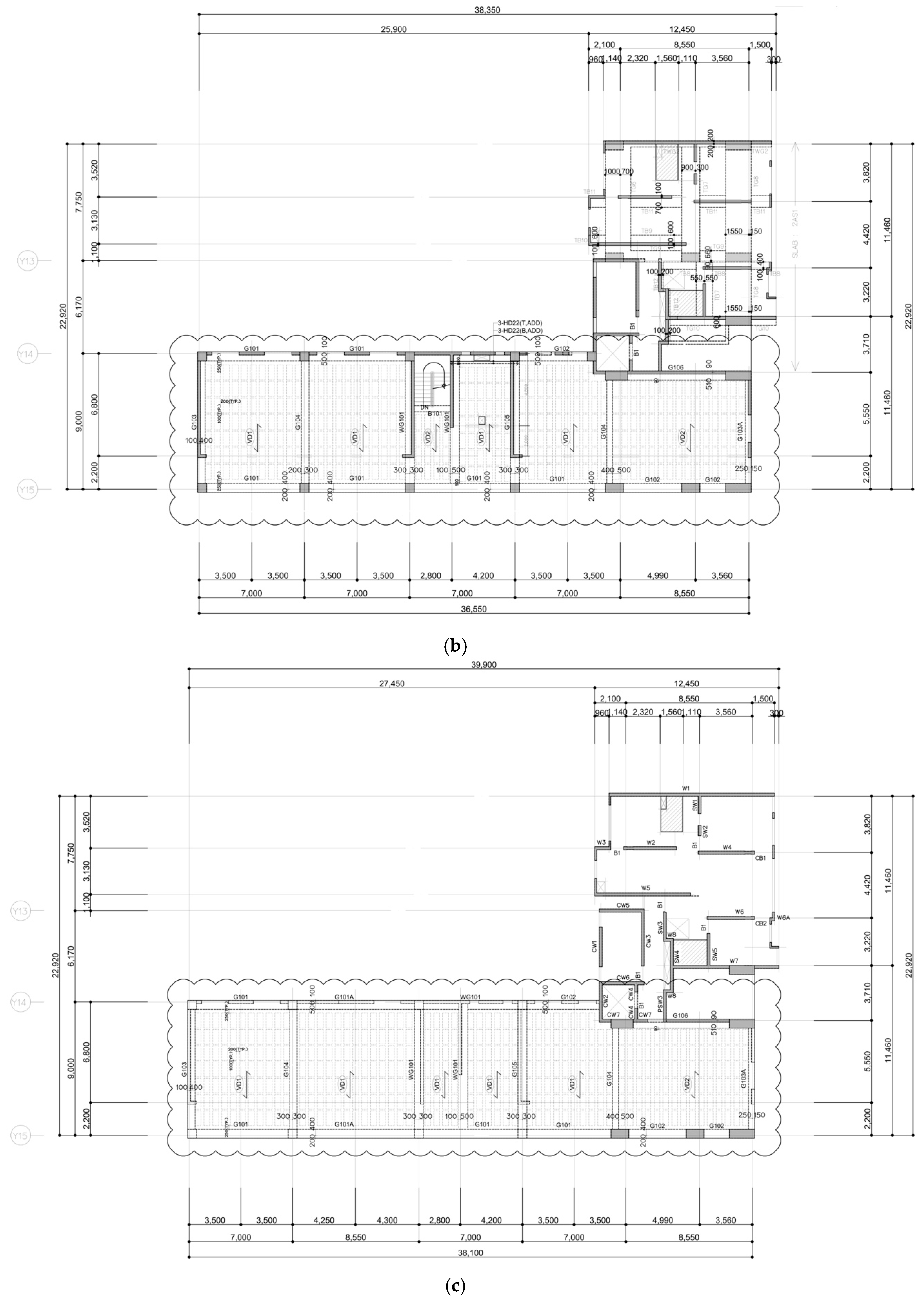
2.2. Overview of the Targeted Building
2.3. Analysis of CO2 Emissions
3. Discussion and Limitations
4. Conclusions
Author Contributions
Funding
Conflicts of Interest
References
- Seto, K.C.; Güneralp, B.; Hutyra, L.R. Global forecasts of urban expansion to 2030 and direct impacts on biodiversity and carbon pools. Proc. Natl. Acad. Sci. USA 2012, 109, 16083–16088. [Google Scholar] [CrossRef] [PubMed]
- Güneralp, B.; Zhou, Y.; Ürge-Vorsatz, D.; Gupta, M.; Yu, S.; Patel, P.L.; Fragkias, M.; Li, X.; Seto, K.C. Global scenarios of urban density and its impacts on building energy use through 2050. Proc. Natl. Acad. Sci. USA 2017, 114, 8945–8950. [Google Scholar] [CrossRef] [PubMed]
- Cuéllar-Franca, R.M.; Azapagic, A. Environmental impacts of the UK residential sector: Life cycle assessment of houses. Build. Environ. 2012, 54, 86–99. [Google Scholar] [CrossRef]
- Park, J.; Tae, S.; Kim, T. Life cycle CO2 assessment of concrete by compressive strength on construction site in Korea. Renew. Sustain. Energy Rev. 2012, 16, 2940–2946. [Google Scholar] [CrossRef]
- Cho, S.H.; Chae, C.-U. The comparative study on the environmental impact assessment of construction material through the application of carbon reducing element-focused on global warming potential of concrete products. Int. J. Korea Inst. Ecol. Archit. Environ. 2015, 33, 149–156. [Google Scholar]
- González, M.J.; Navarro, J.G. Assessment of the decrease of CO2 emissions in the construction field through the selection of materials: Practical case study of three houses of low environmental impact. Build. Environ. 2006, 41, 902–909. [Google Scholar] [CrossRef]
- Climate Change 2007: Synthesis Report. Available online: https://www.ipcc.ch/site/assets/uploads/2018/02/ar4_syr_full_report.pdf (accessed on 19 December 2018).
- United Nations (UN). Kyoto Protocol to the United Nations Framework Convention on Climate Change; United Nations: Kyoto, Japan, 1997. [Google Scholar]
- Kumar, V.; Hewage, K.; Sadiq, R. Life cycle assessment of residential buildings: A case study in Canada. Int. J. Energy Environ. Eng. 2015, 9, 1017–1025. [Google Scholar]
- Van Ooteghem, K.; Xu, L. The life-cycle assessment of a single-storey retail building in Canada. Build. Environ. 2012, 49, 212–226. [Google Scholar] [CrossRef]
- Asif, M.; Muneer, T.; Kelley, R. Life cycle assessment: A case study of a dwelling home in Scotland. Build. Environ. 2007, 42, 1391–1394. [Google Scholar] [CrossRef]
- Baek, C.; Tae, S.; Kim, R.; Shin, S. Life cycle CO2 assessment by block type changes of apartment housing. Sustainability 2016, 8, 752. [Google Scholar] [CrossRef]
- Tae, S.; Baek, C.; Shin, S. Life cycle CO2 evaluation on reinforced concrete structures with high-strength concrete. Environ. Impact Assess. Rev. 2011, 31, 253–260. [Google Scholar] [CrossRef]
- Kim, T.H.; Chae, C.U.; Kim, G.H.; Jang, H.J. Analysis of CO2 emissions characteristics of concrete used at construction sites. Sustainability 2016, 8, 348. [Google Scholar] [CrossRef]
- Chau, C.K.; Yik, F.W.; Hui, W.K.; Liu, H.C.; Yu, H.K. Environmental impacts of building materials and building services components for commercial buildings in Hong Kong. J. Clean. Prod. 2007, 15, 1840–1851. [Google Scholar] [CrossRef]
- Han, Y.-S.; Kim, S.-D. A comparative study on CO2 amount of construction-material in structural design. J. Archit. Inst. Korea Plan. Des. 2005, 25, 203–206. [Google Scholar]
- Nadoushani, Z.S.M.; Hammand, A.W.; Akbarnezhad, A. A Framework for Optimizing Lap Splice Positions within Concrete Elements to Minimize Cutting Waste of Steel Bars. In Proceedings of the 33rd International Symposium on Automation and Robotics in Construction and Mining (ISARC 2016), Auburn, AL, USA, 18–21 July 2016; Vilnius Gediminas Technical University, Department of Construction Economics & Property: Vilnius, Lithuania, 2016. [Google Scholar]
- Cole, R.J. Energy and greenhouse gas emissions associated with the construction of alternative structural systems. Build. Environ. 1999, 34, 335–348. [Google Scholar] [CrossRef]
- Chung, J.H.; Jung, H.S.; Bae, B.I.; Choi, C.S.; Choi, H.K. Two-Way Flexural Behavior of Donut-Type Voided Slabs. Int. J. Concr. Struct. Mater. 2018, 12, 26. [Google Scholar] [CrossRef]
- Valivonis, J.; Popov, V.; Jonaitis, B.; Daugevičius, M. The analysis of concreting process impacts on the behaviour of residual liners of cast-in-situ voided slabs. Arch. Civ. Mech. Eng. 2015, 15, 997–1006. [Google Scholar] [CrossRef]
- Valivonis, J.; Skuturna, T.; Daugevičius, M.; Šneideris, A. Punching shear strength of reinforced concrete slabs with plastic void formers. Constr. Build. Mater. 2017, 145, 518–527. [Google Scholar] [CrossRef]
- Aldejohann, M.; Schnellenbach-Held, M. Investigations on the shear capacity of biaxial hollow slabs-test results and evaluation. Darmst. Concr. 2003, 18, 532–545. [Google Scholar]
- Hwang, H.B.; Kim, S.W.; Hwang, H.S.; Lee, K.J.; Lee, J.Y. Structural performance evaluation of hollow reinforced concrete half slabs. In Proceedings of the Korea Concrete Institute Conference; Korea Concrete Institute: Seoul, Korea, 2008. [Google Scholar]
- Ibrahim, I.S.; Elliott, K.S.; Abdullah, R.; Kueh, A.B.; Sarbini, N.N. Experimental study on the shear behaviour of precast concrete hollow core slabs with concrete topping. Eng. Struct. 2016, 125, 80–90. [Google Scholar] [CrossRef]
- Kang, J.; Park, S.; Kim, G. Application of hollow tube system to concrete slab for improvement of impact sound insulation. Proc. Archit. Instit. Korea Struct. Eng. 2008, 24, 75–82. [Google Scholar]
- Schnellenbach-Held, M.; Pfeffer, K. Punching behavior of biaxial hollow slabs. Cem. Concr. Compos. 2002, 24, 551–556. [Google Scholar] [CrossRef]
- Cho, S.; Na, S. Evaluation of the Flexural Performance and CO2 Emissions of the Voided Slab. Adv. Mater. Sci. Eng. 2018, 2018. [Google Scholar] [CrossRef]
- Cabeza, L.F.; Rincón, L.; Vilariño, V.; Pérez, G.; Castell, A. Life cycle assessment (LCA) and life cycel energy analysis (LCEA) of buildings and the building sector: A review. Renew. Sustain. Energy Rev. 2014, 29, 394–416. [Google Scholar] [CrossRef]
- Asdrubali, F.; Baldassarri, C.; Fthenakis, V. Life cycle analysis in the construction sector: Guiding the optimization of conventional Italian buildings. Energy Build. 2013, 64, 73–89. [Google Scholar] [CrossRef]
- Basbagill, J.; Flager, F.; Lepech, M.; Fischer, M. Application of life-cycle assessment to early stage building design for reduced embodied environmental impacts. Build. Environ. 2013, 60, 81–92. [Google Scholar] [CrossRef]
- Zabalza Bribián, I.; Usón, A.A.; Scarpellini, S. Life cycle assessment in buildings: State-of-the-art and simplified LCA methodology as a complement for building certification. Build. Environ. 2009, 44, 2510–2520. [Google Scholar] [CrossRef]
- Anand, C.K.; Amor, B. Recent developments, future challenges and new research directions in LCA of buildings: A critical review. Renew. Sustain. Energy Rev. 2017, 67, 408–416. [Google Scholar] [CrossRef]
- International Standard Organization. ISO:14040: Environmental Management Life Cycle Assessment Principles and Framework; ISO: Geneva, Switzeland, 2006. [Google Scholar]
- International Standard Organization. ISO:21930: Environmental Declaration of Building Product; ISO: Geneva, Switzeland, 2007. [Google Scholar]
- Korea Environmental Industry. Korea LCI DB Information Network. 2017. Available online: http://www.epd.or.kr/en/lci/lci_intro.asp (accessed on 21 December 2017).
- Ecoinvent. Ecoinvent Version 3.01 Database. 2013. Available online: https://ecoquery.ecoinvent.org/ (accessed on 13 October 2018).
- Korea Institute of Concrete. Structural Concrete Design Code and Commentary; Korea Institute of Concrete: Seoul, Korea, 2012. [Google Scholar]
- American Institue of Concrete. Building Code Requirements for Structural Concrete (ACI 319-05) and commentary (ACI 318R-05); American Institue of Concrete: Farmington Hills, MI, USA, 2008. [Google Scholar]
- American Society of Civil Engineering. Minimum Design Loads for Buildings and Other Structures (7-05); American Society of Civil Engineering: Reston, VA, USA, 2006. [Google Scholar]
- Tae, S.; Shin, S.; Woo, J.; Roh, S. The development of apartment house life cycle CO2 simple assessment system using standard apartment houses of South Korea. Renew. Sustain. Energy Rev. 2011, 15, 1454–1467. [Google Scholar] [CrossRef]
- Kim, T.; Tae, S. A study on the development of an evaluation system of CO2 emission in the production of concrete. J. Korea Concr. Inst. 2010, 22, 787–796. [Google Scholar] [CrossRef]


| Phase | Process | Description |
|---|---|---|
| Raw material | Material processing and transportation | The manufacturing and handling of the raw materials; consuming resources and energy while manufacturing and handling the raw materials. |
| Transportation | Transporting individual materials | The process of transporting raw materials to the manufacturing plants; consuming energy while transporting the raw materials. |
| Manufacturing | Producing construction materials in a factory or by a supplier | The manufacturing of structure materials; consuming the raw materials and energy during the manufacturing of the structure materials. |
| Construction | Material transportation and construction works | The manufactured construction materials are transported from the manufacturing plants to the construction site; assembly of the structure materials to construct the building; operation of various types of construction equipment by construction workers; consuming resources and energy during the building construction. |
| Operation and maintenance | Utilising and maintaining the constructed building | The operation and maintenance of various types of equipment to ensure an indoor environment that is free of equipment downtime; consuming the resources and energy for maintenance and repair. |
| Demolition | Dismantling, transportation, and recycling of waste materials | Disassembly of the building; sorting the components for recycling or disposal; consuming resources and energy during the demolition. |
| Materials | Unit | Emission Factors (kg CO2-eq/Unit) | Resource |
|---|---|---|---|
| Ready-mixed concrete (25-240-15) | m3 | 4.20 × 10² | National LCI DB |
| Steel | kg | 3.40 × 101 | National LCI DB |
| Plywood | m2 | 1.46 × 10² | National LCI DB |
| Expanded polystyrene (EPS) | kg | 6.76 × 10⁻⁹ | National LCI DB |
| Deck plates | m2 | 5.83 × 101 | National LCI DB |
| Diesel | kg | 6.82 × 10⁻² | National LCI DB |
| Petrol | kg | 8.32 × 10⁻² | National LCI DB |
| Electricity | kWh | 4.95 × 10⁻⁵ | National LCI DB |
| Materials | CO2 Emissions (kg CO2-eq) | Variation (%) | |
|---|---|---|---|
| Ordinary Slab | Void Slab | ||
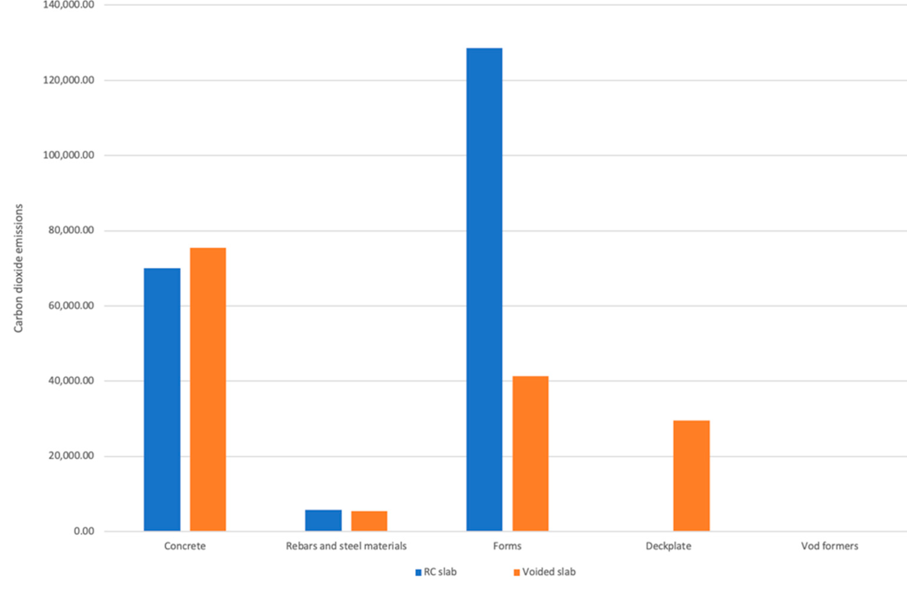
| Ready-mixed concrete | 70,043.40 | 75,381.60 | 7.08 |
| Rebars and steel materials | 5773.88 | 5409.40 | −6.74 |
| Moulds | 128,615.78 | 41,259.60 | −211.72 |
| Deck plates | - | 29,576.35 | - |
| Void formers | - | 8.82 × 10⁻⁶ | - |
| Transportation | 110.07 | 127.80 | 13.09 |
| Total | 204,544.13 | 151,754.75 | −33.99 |
| Materials | Quantity | Unit | CO2 Emissions (kg CO2-eq) | Percentage |
|---|---|---|---|---|
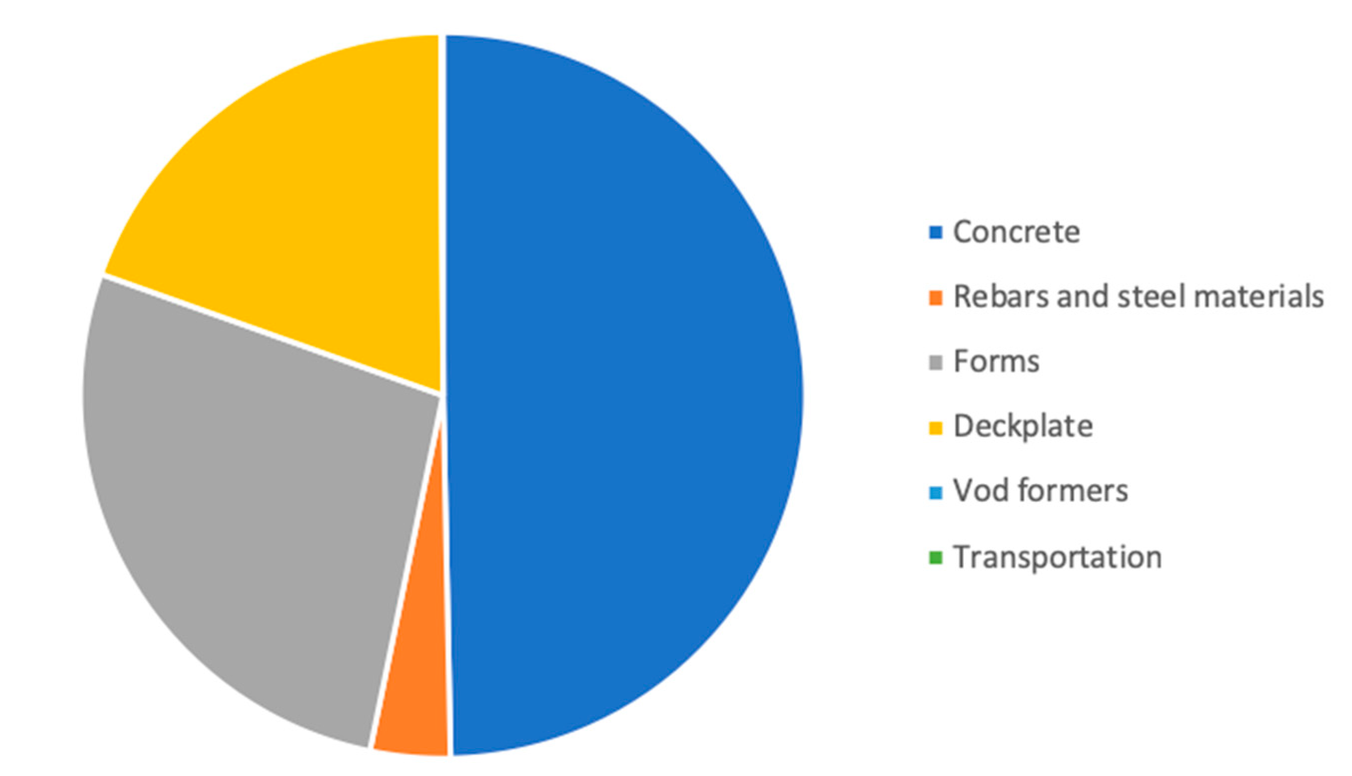
| Ready-mixed concrete | 166.77 | m3 | 70,043.40 | 33.6 |
| Rebars and steel materials | 16,982.00 | kg | 5773.88 | 2.8 |
| Moulds | 880.93 | m3 | 128,615.78 | 61.7 |
| Transportation | - | - | 111.07 | 0.1 |
| Total | 204,544.13 | 100.0 |
| Materials | Quantity | Unit | CO2 Emissions (kg CO2-eq) | Percentage |
|---|---|---|---|---|
| Ready-mixed concrete | 179.48 | m3 | 75,381.60 | 49.7 |
| Rebars and steel materials | 15,910.00 | kg | 5409.40 | 3.6 |
| Moulds | 282.60 | m3 | 41,259.60 | 27.2 |
| Deck plates | 507.40 | m2 | 29,576.35 | 19.4 |
| Void formers | 1305.92 | kg | 8.8 × 10⁻⁶ | 0.0 |
| Transportation | - | - | 127.80 | 0.1 |
| Total | 151,754.75 | 100.0 |
© 2018 by the authors. Licensee MDPI, Basel, Switzerland. This article is an open access article distributed under the terms and conditions of the Creative Commons Attribution (CC BY) license (http://creativecommons.org/licenses/by/4.0/).
Share and Cite
Paik, I.; Na, S.; Yoon, S. Assessment of CO2 Emissions by Replacing an Ordinary Reinforced Concrete Slab with the Void Slab System in a High-Rise Commercial Residential Complex Building in South Korea. Sustainability 2019, 11, 82. https://doi.org/10.3390/su11010082
Paik I, Na S, Yoon S. Assessment of CO2 Emissions by Replacing an Ordinary Reinforced Concrete Slab with the Void Slab System in a High-Rise Commercial Residential Complex Building in South Korea. Sustainability. 2019; 11(1):82. https://doi.org/10.3390/su11010082
Chicago/Turabian StylePaik, Inkwan, Seunguk Na, and Seongho Yoon. 2019. "Assessment of CO2 Emissions by Replacing an Ordinary Reinforced Concrete Slab with the Void Slab System in a High-Rise Commercial Residential Complex Building in South Korea" Sustainability 11, no. 1: 82. https://doi.org/10.3390/su11010082
APA StylePaik, I., Na, S., & Yoon, S. (2019). Assessment of CO2 Emissions by Replacing an Ordinary Reinforced Concrete Slab with the Void Slab System in a High-Rise Commercial Residential Complex Building in South Korea. Sustainability, 11(1), 82. https://doi.org/10.3390/su11010082