Article

Performance-Based Evaluation of a Double-Deck Tunnel and Design Optimization

1
Department of Civil Engineering, INHA University, 100, Inha-ro, Nam-gu, Incheon 22212, Korea
2
Energy School, Xi’an University of Science and Technology, Xi’an 710054, China
3
School of Energy, Construction and Environment, Faculty of Engineering, Environment and Computing, Sir John Laing Building, Coventry University, Coventry CV1 2LT, UK
*
Author to whom correspondence should be addressed.
Sustainability 2019, 11(1), 201; https://doi.org/10.3390/su11010201
Submission received: 18 December 2018 / Revised: 25 December 2018 / Accepted: 26 December 2018 / Published: 3 January 2019

Abstract

:
The double-deck tunnel is well known as smart infrastructure because multiple sections can be used for various purposes. Although the stability of a double-deck tunnel is mainly governed by the intermediate slab, the effect of various governing factors on tunnel structural stability has not been fully investigated. In this study, performance-based evaluation method for a double-deck tunnel is suggested as a three-dimensional matrix considering the life cycle of a double-deck tunnel. Moreover, a customized software for design and maintenance of a double-deck tunnel is developed. A structural analysis solver based on a beam–spring model for a double-deck tunnel was embedded in this code. The effects of connection type as well as depth of tunnel, ground stiffness and traffic load on structural behavior of tunnel were investigated. From the analysis, it was found that the connection type between segment lining and intermediate slab significantly affects the behavior of segment lining: simply connected condition causes lesser stress and moment than fully fixed condition. The deeper the tunnel depth, the greater the member force of segment lining. In addition, as both the tunnel depth and the ground stiffness increase, the influence of connection type on the structural stability of the double-deck tunnel becomes insignificant.

1. Introduction

A circular tunnel driven by a tunnel boring machine (TBM) with a circular cutterhead was the typical shape of mechanized tunnels. However, a circular tunnel section includes unwanted spaces for transport structures. For example, the invert should be filled after tunneling for installation of railway track or pavement. Recently, to increase the spatial efficiency of circular tunnel, multiple intermediate slabs divides circular tunnel into multiple sections. A double-deck tunnel can be considered as a representative multi-section tunnel. Double-deck tunnels are special tunnels that are able to secure multiple spaces separated by one excavation. Two internal decks can host two-way traffic in a single tunnel and the invert can be used for multiple purposes such as water storage and utility chamber. Bobylev [1] refers to utility and transport as a most common of urban underground infrastructure (UUI), and double-deck tunnels are well suited for this type of tunnel. Until now, the A86 tunnel (France), Ome tunnel (Japan), and Stormwater Management And Road Tunnel (SMART tunnel, Malaysia) are operating double-deck tunnels. In particular, SMART tunnels are designed to turn from traffic tunnel to flood prevention tunnel several times a year, and are used for various purposes other than traffic [2]. The installation of intermediate slab is troublesome since it includes various construction stages even after the tunneling: installation of bracket, installation of intermediate slabs, fire protection, and pavement etc. Kim and Kim [3] investigated the shape and support method of the slab, and calculated slab thickness and the sectional area available for the lower space using the structural analysis. Park et al. [4] carried out a numerical analysis on the stress concentration phenomena caused by the emergency escape route located in the intermediate slab. Based on their study, it was confirmed that the stress concentration phenomenon occurs in the cantilever-type intermediate slab in order to secure an emergency evacuation route. This suggests the need to reinforce the cantilever-type intermediate slabs. Lee and Moon [5,6] carried out the analysis of member strength by using the intermediate slab installation, connection type, and lateral earth pressure coefficient at rest (K0) for analysis of the effects of installation of intermediate slab on the double-deck tunnels. They suggested that the connection type of intermediate slab is significant influential factors affecting on the structural stability of segment lining.
To assess the stability of the tunnel, a review of stress–strain behavior of the lining is required. ITA [7] classified the behavior of tunnel segment due to external loads based on the analytical model and the numerical model. Unlike analytical methods with inherent limitations such as section shape and ground conditions, numerical methods are able to reflect complex structural features i.e., joints of segment lining as well as section shape and ground conditions [8]. Among the various numerical methods, the beam–spring method is a simple and powerful analysis technique that allows the simulation of tunnel structures and ground elements. In this method, the lining and slab of the tunnel are modeled as linear elastic beams, and the soil is modelled by spring. Displacement, stress and strain can be calculated and this can be used to describe the tunnel stability. The stiffness matrix of structures for analysis are relatively easy to construct and have been used for various studies. For instance, Klar et al. [9] applied a beam–spring model to analyze the effect of tunnel excavation and pipeline on subsidence. In that study, the stiffness degradation and interaction with the ground are modeled and reflected in the numerical analysis, and tunnel excavation results show that the joint pipeline has a smaller maximum bending moment than the continuous pipeline. Lee et al. [10] proposed a rational design concept for segment lining design by comparing load cases and member strength according to the combination, and compared the theoretical method with the beam–spring model. Further, Nikkhah et al. [11] analyzed the effect of the rotation spring stiffness on the segment connection and the spring stiffness in the beam–spring model.
Although the various governing factors affecting on the intermediate slab and segment lining should be carefully examined to ensure the structural stability of the double-deck tunnel, few numbers of studies have been conducted. Thus, in present study, performance-based evaluation method for a double-deck tunnel is suggested as a three-dimensional matrix considering the life cycle of a double-deck tunnel. Moreover, a customized software for design and maintenance of a double-deck tunnel is developed. A structural analysis solver based on beam–spring model for the double-deck tunnel was constructed in this code. The effects of connection type as well as depth of tunnel, ground stiffness, traffic load on structural behavior of a double-deck tunnel were investigated.

2. Definition of Performance, Structural Elements and Life Cycle

2.1. Performance-Based Evaluation

The infrastructures are focused on securing the safety by specifying construction materials and methods based on specifications during design and construction. However, the performance-based design which designs the structures for various performances such as usability and durability has been introduced to meet the construction purpose of the structure for the expected lifetime since the European design standard, Eurocode, started.
Unlike the prescribed design regulation, it is necessary to define the purpose and functionality for the design, construction and maintenance of structures based on the performance [12,13]. In this study, the purpose and functionality for the double-deck tunnel is a traffic tunnel to solve the saturated traffic in urban area. It is designed to run the vehicle safely and comfortably at a predetermined speed. In order to achieve the purpose as the traffic tunnel, the performance of the double-deck tunnel should be classified as safety, usability/functionality and durability as shown in Table 1.
The double-deck tunnel located in the underground space is influenced by not only ground load depending on depth of the tunnel, groundwater pressure and surcharging but also traffic load due to flow inside of the double-deck tunnel. The tunnel should be safe in structural guarantee from the load condition. In addition, it is necessary to secure the usability and functionality of the double-deck tunnel from the factors that cause discomfort to the user such as deformation and vibration of the double-deck tunnel or restrict the function of the structure. It also needs to maintain the expected performance of the double-deck tunnel throughout the lifetime by examining the factors related to the durability of the double-deck tunnel such as the environment in which the double-deck tunnel is constructed or construction materials.

2.2. Components of a Double-Deck Tunnel

The main structural elements composing the double-deck tunnel are ground, segment lining, invert and middle slab. The ground is a factor that determines the influence of the load on the tunnel as well as the spatial background in which the tunnel is located. According to the ground conditions, the load applied to the tunnel is composed with total earth pressure and the ground water pressure. Also, the characteristics of the ground should be considered because it affects the deterioration of the concrete material depending on the characteristics of the ground.
The segment is defined as ‘a unit piece consisting of the segment lining used in the shield tunnel’, ‘arched structures forming a primary lining of a shield tunnel’ [7]. Sufficient strength and durability are required for the segment lining because it is required to resist not only the load due to the ground but also the construction load and the traffic load during operation. In addition, shape design and segmentation of segment lining are influential on economic efficiency and construction of tunnel [14].
The invert is located in the lower part of the shield tunnel and it is the structural element that supports traffic load and secure the space for facilities. In addition, it is guaranteed the stability of tunnel from the excessive load.
The middle slab is a structural element that separates the inner space of the double-deck tunnel from the upper and the lower part. Unlike a general road pavement slab, the middle slab is installed on the brackets that are fully fixed with segment lining and both ends of the slab are placed on the bracket. This is one of the factors that should be considered in the performance-based evaluation of the double-deck tunnel because it affects not only the behavior of the tunnel but also the stress distribution of the whole double-deck tunnel [15,16].
Infrastructures, including double-deck tunnels, undergo a life cycle of planning, design, construction and maintenance. And during this period, there is so much relationship with relevant stakeholders. Therefore, it is necessary to clarify this relationship and to carry out efficient construction project by systematically informing important information at each phase of life cycle. In this study, three phases of design, construction and maintenance are defined. In the design phase, the specifications and design factors of the double-deck tunnel should be managed in order to satisfy the expected performance of the double-deck tunnel. And the construction quality should be managed by increasing the degree of the performance in the construction phase. In the maintenance phase, the maintenance and repair should be thoroughly carried out so the performance of the double-deck tunnel is secured through the design and construction phases.

3. Principal Factors of a Double-Deck Tunnel for Performance-Based Evaluation

3.1. Derivation

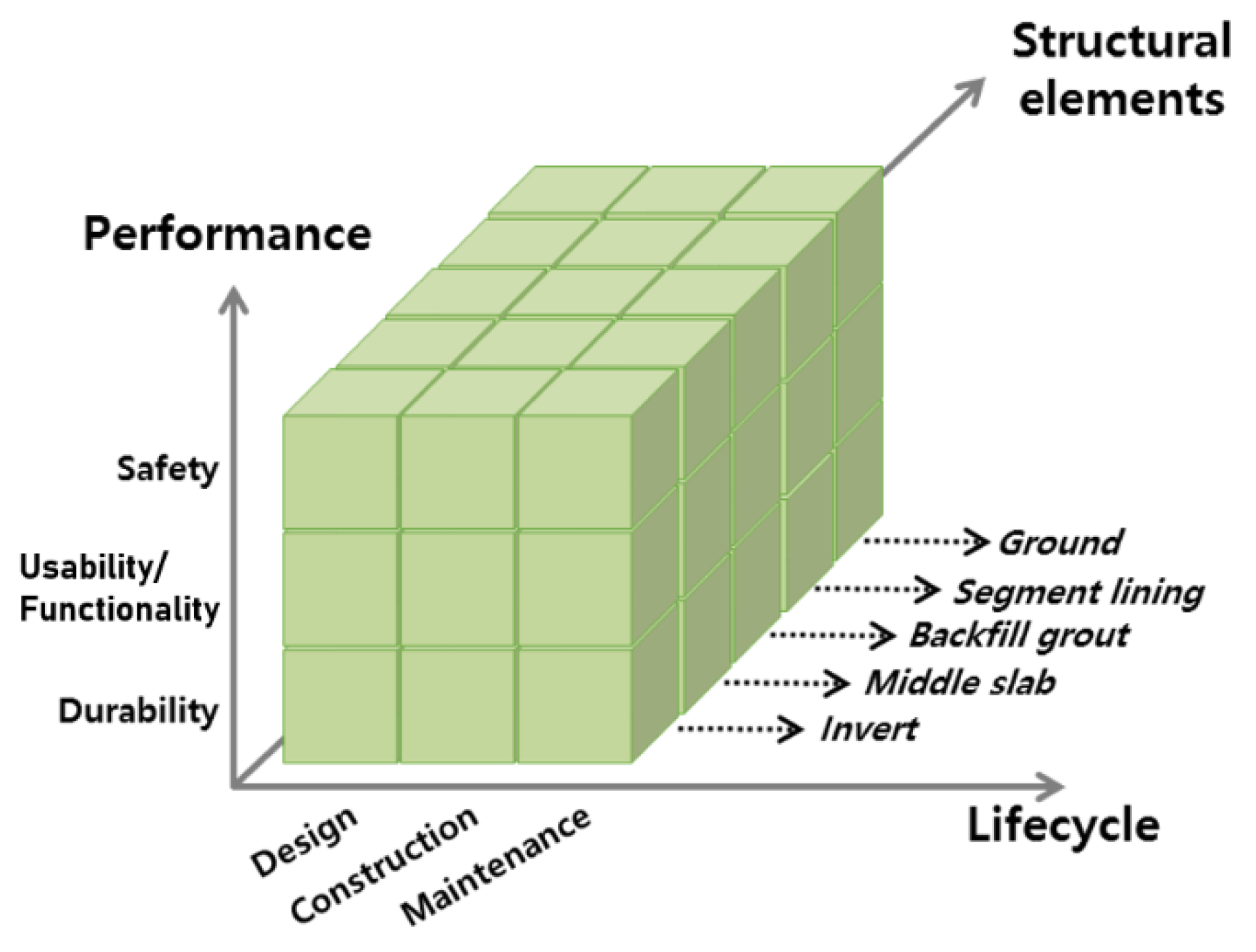
In this study, important factors affecting the performance of the double-deck tunnel are derived. The life cycle informatization is organized based on the performance, the structural elements and the life cycle. For the purpose informatization, domestic and foreign literature surveys are conducted to collect and analyze existing information. Information is gathered through additional consultation on areas where expert advice is needed. Based on this, the performance, the structural elements and the life cycle definition and the principal factors of a double-deck tunnel are derived. In addition, by gathering opinions from various field advisors such as experts in design technology related to the double-deck tunnel, tunnel construction and structural safety inspection, the principal factors derived from the literature survey are verified and supplemented. In particular, in the case of the middle slab, the opinions of the advisors are reflected because there are very few cases where technical reports and research examples are disclosed. In order to evaluate the performance of the double-deck tunnel, the principal factors considered in the life cycle (design, construction and maintenance phase), the structural elements (ground, segment lining, backfill grout, invert and middle slab) are derived and informed in the form of a three-dimensional matrix as shown in Figure 1. This matrix means that the performance of the double-deck tunnel is secured when each of the principal factors is satisfied.

3.2. In Design Phase

Table 2 summarizes the important factors to be considered in the design phase of the double-deck tunnel. The ground surrounding the tunnel not only determines the load on the tunnel, but also influences the stress behavior of the tunnel through interaction with the tunnel. Therefore, when analyzing the safety of the double-deck tunnel, both of properties and structural conditions of the ground should be considered. In addition, ground surface settlement and groundwater condition should be confirmed at the design stage so that the completed double-deck tunnel does not deteriorate the expected traffic capacity due to subsidence and groundwater leakage. Since the double-deck tunnel structure must maintain its initial performance over a long period of time, preliminary investigations of deterioration factors in the ground such as penetration of sulfate, magnesium and salt damage which cause deterioration of concrete structures should be performed.
The segment lining, the invert and the middle slab are reinforced concrete structures that constitute the double-deck tunnel and must be stable in material and structural aspects of concrete. Particularly, the segment lining is a support for supporting the external load applied to the double-deck tunnel but the failure of joint between segments can cause inflow of groundwater. So, it must be considered in terms of safety, usability/functionality and durability of the multi-layer tunnels.
The invert and middle slabs are structural elements that directly receive the load of the vehicle. Particularly, in the case of the middle slab, unlike the invert, the load received by the slab is supported only at the both ends, so it is necessary to consider the supporting method of the middle slab. The supporting method of the middle slab can be divided into fixed support, simple support and mixed support [15,16]. Because there is a difference of member force distribution due to the load from the middle slab depending on the supporting method, it is necessary to consider the support method of the middle slab. The tunnels should provide space for disaster and maintenance facility inside the tunnels. Therefore, it is necessary to secure the place for the facility in the consideration of the design of the invert.
The backfill grout, which affects the multi-layered tunnel and the ground behavior, should be inspected for the injection condition so that the external load acts uniformly along the tunnel surface, and appropriate injection method should be selected considering the construction conditions. Also, the backfill grout should be watertight to the groundwater flowing into the double-deck tunnel from the ground after the completion of the injection.

3.3. In Construction Phase

Table 3 summarizes the important factors to be considered in the construction phase of the double-deck tunnel. During the tunnel construction, the ground is deformed due to the change of the stress distribution of the ground at the same time as excavation. Therefore, in the construction process, the time required for the excavation of the ground and set up the supporting material has to be considered. The time and deformation rate of the ground are applied as factors to estimate amount of over break during tunneling. However, when calculating the amount of over break, gap parameter from measurement error or tail void causes imperfect closure between the excavation surface and the segment lining after assembling the segment lining. It makes cavities beyond the segment lining and has a bad influence on the behavior of segment lining or ground. Therefore, it is necessary to check the excavation progress status such as the penetration rate and the discharging rate of TBM when constructing the double-deck tunnel so that the over break should not be occurred.
Segment lining, which is the main support material of shield tunnels, is called precast segments and is prefabricated and transported to the site for assembly. Although segments can be expected to shorten construction time and uniform quality, there is risks of damage during storing and transporting in the field, and damage due to construction load, such as thrust force of hydraulic jacks for advancement of TBM and fastening of segment bolt. The damage of the segment lining during the construction process is cause of failure of the segment lining to support the design load determined at the design stage of the double-deck tunnel, which not only threatens the safety of the multi-layer tunnel, but also causes a decrease in function. Therefore, care should be taken not to deteriorate the function of the double-deck tunnel due to the damage of the segment in the construction of the double-deck tunnel.
In addition, when assembling the segment lining, it is necessary to pay attention in the segment assembling process because the bolt fastening condition and the step between segments cause the degradation of the double-deck tunnel due to the stress behavior and watertightness of the segment lining. Also, proper construction of the water stop rubber is necessary to prevent leakage from the joint part of the segment. The backfill grout is measured pressure at the construction phase and the injection condition and completion are evaluated by the pressure. In order to fill the cement grout without voids beyond the segment lining, it is necessary to satisfy the constant injection pressure. Also, after the injection is completed, the finishing work of the injection hole located in the segment lining is thoroughly completed so that the deterioration of usability and durability of the double-deck tunnel due to leakage of the ground water should not be occur.
The invert and the middle slab can be categorized into two kinds: in-site slab and precast slab. On most of the sites, precast slabs are preferred because of their ease of construction and construction costs. Therefore, care should be taken not to damage the precast slab during installation, transportation, and installation. And thoroughly tighten the joint where the slab is assembled so that the slab is not dropped during operation. In addition, the drainage system should be secured so that the groundwater does not obstruct the traffic flow or adversely affect the durability of the slab.

3.4. In Maintenance Phase

In the maintenance stage as tabulated in Table 4, the state of the double-deck tunnel structural elements is checked mainly by visual or measurement equipment. After the completion of construction, it is difficult to survey the condition of the ground beyond the segment lining, except for the measurement on the ground. Therefore, state of the ground surrounding double-deck tunnel is indirectly surveyed through the settlement observed from the surface of the earth or directly measured through the sensors buried before installing the segment lining. Meanwhile, nondestructive testing techniques using P- and S-waves, electromagnetic waves and X-rays have been utilized to monitor the structure and ground responses in tunnels [17,18,19].
Since the structural elements composing the double-deck tunnel are mostly reinforced concrete structures, they must be able to withstand external loads for a long period of time. Therefore, periodic inspection and maintenance are required so that deterioration of reinforced concrete should be prevented. Cracks in structures and corrosion of exposed steel bars should be checked and immediate repair is required when problems occur. In the case of segment lining, it is necessary to prevent the inner section of the double-deck tunnel from closure by the deformation of the fastening state and the segments member. In case of the invert and the middle slab, the deflection caused by the traffic load should be controlled not to exceed excessively. In particular, in the case of the middle slab, the condition of the elastic mat of the bracket located between both ends of the slab and bracket should be checked so that the load received by the middle slab does not damage the brackets and segment lining.

4. Structural Models for Tunnel Segment Lining

4.1. Analysis Method of Segment Lining

Segment lining, which is the main support structure of the tunnel, is the main structural element to secure the stability of the tunnel from external load, traffic load and environmental impacts. Therefore, it is necessary to evaluate the performance of the support of the segment lining considering the shape of tunnel, and boundary conditions. According to ITA [7], the method of evaluating the structural stability of segment lining can be classified into (a) analytical method and (b) numerical analysis method; knowing that each method has its’ own advantages and disadvantages. Analytical methods such as elastic equation method and Terzaghi relaxed earth pressure model are relatively easy to calculate compared to other methods. Therefore, elastic equation method and Terzaghi relaxed earth pressure model may be used for numerical analysis or for verification of preliminary design. However, the analytical method assumes that the segment lining has uniform stiffness and there are restrictions in applying the shape and condition of the tunnel [8]. On the other hand, numerical analysis method can define the geological profile, constitutive model of materials, geometry of tunnel structure and analyze the displacement and stress of ground as well as tunnel structure. Numerical analysis methods include Beam–spring model, finite element method and finite differential method. Since the beam–spring model can represent the stiffness degradation at the segment connection and can be applied to the analysis of the stress behavior of the segment lining unlike the analytical method, various studies have been conducted over a long period of time [9,10,11].

4.2. Beam–Spring Model of Segment Lining

The segment lining of a double-deck tunnel is composed with precasted segments and it is assembled inside the TBM by using erector. Precasted slab blocks also can be used as intermediate slab for simple connection type. However, cast-in-place slab should be used for the fixed connection type. Now, the assembled portion of the segment has a lower flexural stiffness than each segment [20].
The models I–IV are 2D models that can calculate the transversal behavior of segment lining and does not consider the longitudinal elements of the double-deck tunnel. Model I is a segment lining model with uniform stiffness without consideration of stiffness degradation due to joints, model II considered uniform stiffness degradation over the whole segment lining, considering the stiffness reduction effect. For models III, and IV, the connections of the segment lining can be expressed as a hinge or a rotating spring, thereby giving the position and direction of the stiffness reducing effect. Finally, models V and VI are three dimensional, which can consider the behavior of segment lining in the longitudinal direction by expressing the connection of neighboring segment rings by rigid elements or shear springs. It can be considered that the models III–VI are advanced models. However, those models require joint properties that must be assumed without a real scale experimental test. Considering the purpose of this study, to investigate the structural behavior of segment lining due to connection type of intermediate slab, simple model is appropriate. Thus, model II is adopted in this study as the beam–spring structural model for double-deck tunnel.
The beam–spring model of the double-deck tunnel consists of a beam element representing the segment lining and a spring element representing the ground reaction force. Although the actual segment lining is circular due to arc shaped segments, the transversal segment lining model should be expressed as polygon due to linear form of a beam element. However, circularity of transversal model can be obtained with the increase of the beam element number.
Since the beam–spring model can define the interaction between ground and segment lining, it can simply analyze the behavior of segment lining due to external and internal load. Generally, the ground reaction spring is radially connected at each node to apply the ground reaction force to the segment lining [21]. In addition, there is a case in which a ground reaction spring is installed in the tangential direction with respect to the segment lining to consider the action caused by the reduction in frictional resistance between the ground and the segment lining, but only the radial ground reaction spring is applied from a conservative viewpoint.
[ K b e a m s ] = E L [ A C 2 + 12 I L 2 S 2 ( A 12 I L 2 ) C S 6 I L S ( A C 2 + 12 I L 2 S 2 ) ( A 12 I L 2 ) C S 6 I L S A C 2 + 12 I L 2 C 2 6 I L C ( A 12 I L 2 ) C S ( A C 2 + 12 I L 2 S 2 ) 6 I L C 4 I 6 I L S 6 I L C 2 I A C 2 + 12 I L 2 S 2 ( A 12 I L 2 ) C S 6 I L S s y m m e t r y A C 2 + 12 I L 2 C 2 6 I L C 4 I ]
[ K g s p r i n g ] = K [ C 2 C S C 2 C S C S S 2 C S S 2 C 2 C S C 2 C S C S S 2 C S S 2 ]
The global stiffness matrix of a beam–spring model of a double-deck tunnel is composed of element stiffness matrixes of beam element (Equation (1)) and a spring element (Equation (2)). The symbols used in the matrixes are the elastic modulus of segment lining (E), cross section of the segment lining (A), the moment of inertia (I), the length of the beam element (L), Cosine component (C) and sine component (S) of the ground reaction force spring for the angle of rotation that occurs when switching from the local coordinate system to the global coordinate system. The global stiffness matrix of beam–spring model is obtained by adding contributing element stiffness matrixes of beam elements and spring elements to the global stiffness matrix at associated node position of the model. Not only the load and displacement of the model but also the stiffness matrix of the beam elements and the spring elements, which are constituent elements, should be expressed in the global coordinate system.

4.3. Beam–Spring Model of the Intermediate Slab

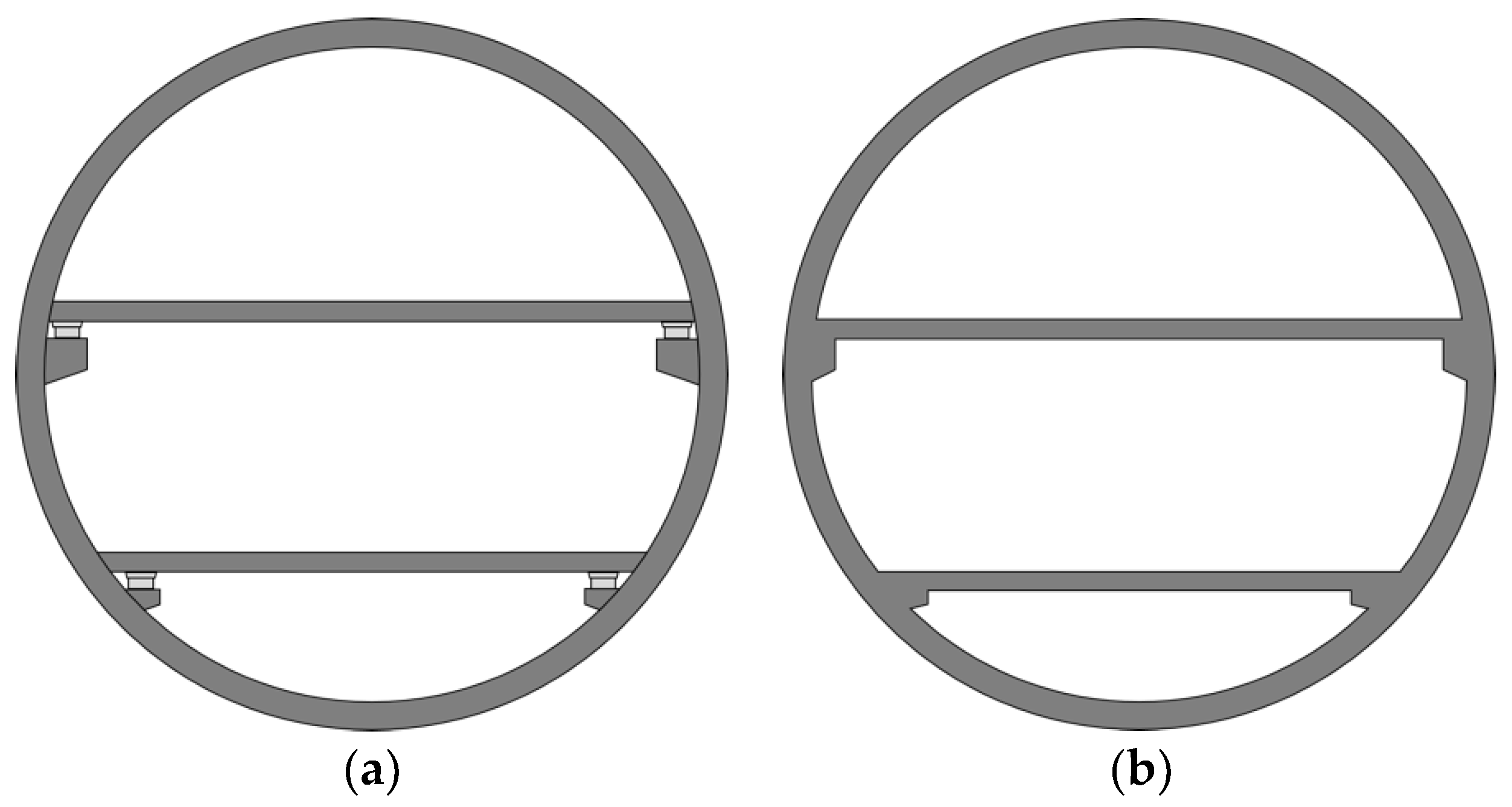
The intermediate slab of the double-deck tunnel is a structural component inside the tunnel and it supports the load of vehicle passing over the intermediate slab and the self-weight of the intermediate slab. Figure 2 shows the representative connection type of intermediate slab. For example, the Duplex A86 tunnel in Paris, France, was designed as a simple connection type as shown in Figure 2a. The intermediate slab is simply supported by bracket and the slab is not physically binded with segment lining. In the case of simple connection type, bracket installed in the segment lining is a structure that supports the load of the traffic load and intermediate slab. The SMART tunnel in Kuala Lumpur, Malaysia, was designed with a fixed connection type as shown in Figure 2b, the steel bar physically binds the cast-in-place concrete slab with a bracket. Because the intermediate slabs are combined with the segment lining and bracket, thereby movement of all structural components are influenced by traffic load [6].
For numerical analysis on the structural behavior of segment lining and intermediate slab, the connection type of intermediate slab should be simplified. When the both ends of intermediate slab are separated from bracket, it can be considered as simple beam model as shown in Figure 3a. In the case of simple-connection type, the self-weight of intermediate slab and traffic load are transferred to the segment lining from both ends to the vertical load as they are simply supported at the upper ends of the bracket. However, in the case of a fixed-connection type as shown in Figure 3b, both ends of intermediate slab are fully bonded to the segment lining and it can be considered as fixed condition. When both ends of intermediate slab are fixed, rotation is restrained, and moment is transferred the segment lining due to traffic load and self-weight of intermediate slab.

5. Beam–Spring Analysis of a Double-Deck Tunnel

5.1. Analysis Process

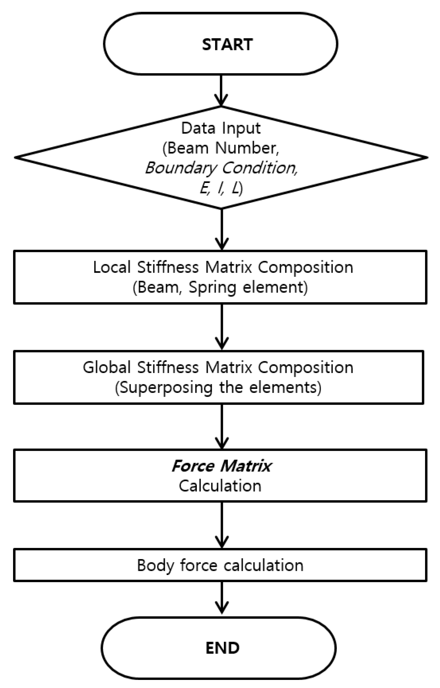
The analysis sequence of the double-deck tunnel is shown in Figure 4. First, the load condition of the model and the ground reaction force condition should be determined based on the shape, ground condition, and specification of segment lining and intermediate slab. Load vector can be constructed with given information. Considering the input parameters, the elements stiffness matrices of the beam element and spring element constitute the global stiffness matrix of the double-deck tunnel model. According to the relationship between force and stiffness and strain, the deformation of the double-deck tunnel can be calculated with the inversed global stiffness matrix and the load vector. Finally, the distribution of member force such as bending moment and shear force of the segment lining and intermediate slab can be obtained.

5.2. Double-Deck Tunnel Model

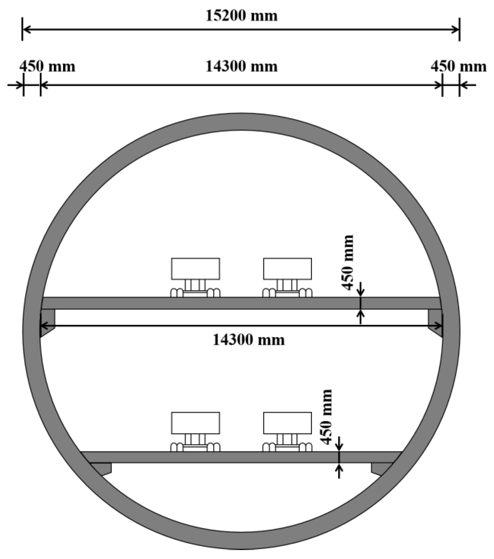
The specifications of the double-deck tunnel used in the present study are shown in Figure 5. The outer diameter of the tunnel is 15.2 m, the thickness of the segment lining is 450 mm, and the width of the segment lining is set to 2 m. The thickness of the intermediate slab is 450 mm. The upper intermediate slab is installed and assigned to be horizontally crossed at the center of the tunnel at 90° and 270° and lower intermediate slab is installed at 70° and 290° in the clockwise direction with respect to the invert of the tunnel, respectively. In addition, the upper slab length and lower slab length are 14.3 m and 12.5 m. The segment lining consisted of eight segments including key segments. However, since the beam–spring model II was adopted as discussed in the previous chapter, the stiffness reduction effect due to the segment connection is simplified by the decrease of stiffness.
Table 5 summarizes the material properties for analytical model of segment lining and intermediate slab. Since the stiffness of the transversal joints of the segments is lower than the stiffness of the segments, the stiffness of the joints in the beam–spring model should be considered. Muir wood [22] proposed Equation (3) for consideration of the stiffness reduction effect due to transversal segment joint.
I e = I j + ( 4 n ) 2 · I   ( I e I ,   n > 4 )
where I e is the effective moment of inertia and can be obtained by considering the moment of inertia of transversal joint ( I j ), the moment of inertia of the segment lining ( I ), and the number of segments ( n ). The moment of inertia of segment joint is normally smaller than that of segment. It is influenced by various factors such as the shape of the joint, type of waterproof gasket, and bolt connection type. The moment of inertia should be obtained with large scale experimental test. However, it needs huge cost and considerable time. To consider the stiffness reduction effect due to segment joint, Bickel et al. [23] suggested that the stiffness of jointed segment should be reduced to 60~80% of the segment stiffness. In this study, according to Bickel et al. [23], 70% of segment stiffness is adopted as stiffness of jointed segment and thus, the effective moment of inertia was determined to be 1.059 × 10 2   m 4 .
Table 6 summarized the properties of the ground condition. The spring coefficient of ground ( K r ) can be calculated with Equation (4) which is proposed by USACE [24] by using elastic modulus of ground ( E g r o u n d ), Poisson’s ratio ( ν ) and tunnel radius (R). Three different ground stiffnesses (3.52, 7.04, 10.56 MPa) are assumed to analyze the effect of the elastic modulus of ground on the member force of the segment lining and intermediate slab.
K r = E g r o u n d R ( 1 + ν )
In the transversal beam–spring model, one or two ground reaction springs are generally installed at each node. Since entire external area of the segment lining is attached to the ground, the interaction between ground and segment lining should be considered. The stiffness of the ground reaction spring for the beam–spring model should be determined considering the contributing area where each spring is located. In this study, the modified spring coefficient of the ground reaction force was obtained based on Equation (5) because each spring shares the half-length of the neighboring beam elements.
K r ( e a c h   u n i t   s p r i n g ) = K r   · ( 2 × l 2 ) · L

5.3. Analysis Cases

In this study, the effects of connection type as well as depth of tunnel, ground stiffness, traffic load on structural behavior of a double-deck tunnel were investigated. Two representative connection types are examined: simple connection type and fixed connection type. To analyze the effects of earth pressure due to tunnel depth, three different tunnel depths (10, 20 and 30 m) were also considered as well as three different ground stiffnesses. The horizontal earth pressure is obtained considering the lateral earth pressure coefficient at rest ( K 0 ) and vertical earth pressure acting on the tunnel crown. Vertical earth pressure is assumed as uniformly distributed load and horizontal earth pressure is trapezoidal with minimum at the top of tunnel and maximum at the bottom of tunnel. Three different traffic load cases are considered in this study as tabulated in Table 7. The vertical load acting on the intermediate slab is the sum of the weight of the intermediate slab and the traffic load. The weight of concrete is calculated with the unit weight of the concrete and the volume of the intermediate slab. In the case of simple connection type, the traffic load is applied at the segment lining where both ends of two intermediate slabs are located. In the case of fixed connection type, the wheel load is modeled as point load acting on the physically modelled intermediate slab. The study cases are tabulated in Table 8.

5.4. Effect of Connection Type of Intermediate Slab

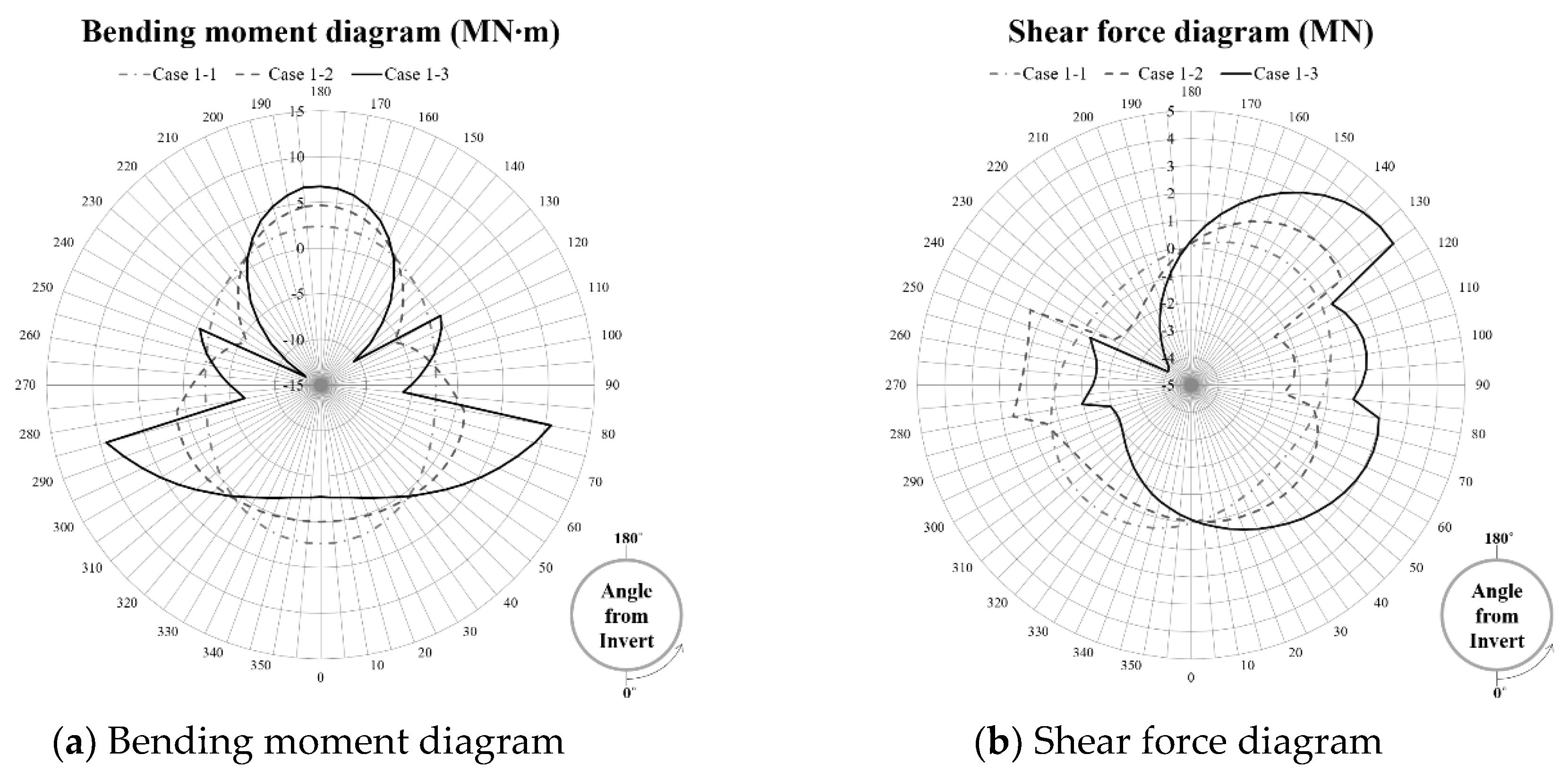
Figure 6a,b illustrates the bending moment diagram and shear force diagram depending on the connection type of intermediate slab. When the intermediate slab is not installed (Case 1-1), a maximum bending moment of 2.37 MN·m occurs at the crown and bottom of segment lining, and a minimum bending moment of −2.37 MN·m can be found at the spring line. The maximum shear force was 0.68 MN at 140° and 320° from the tunnel invert (0°), and the minimum shear force was −0.68 MN at 50° and 230°. When the intermediate slab is not installed, the bending moment and shear force show oval distribution. When intermediate slab is simply connected (Case 1-2), a maximum bending moment of 4.66 MN·m occurred at the tunnel crown, and a minimum bending moment of −5.65 MN·m occurred at the location of the upper slab. Maximum shear force of 1.94 MN and minimum shear force of −1.94 MN were found around the bracket of upper intermediate slab. In case of fixed connection type (Case 1-3), bending moment of 6.73 MN·m occurred at the tunnel crown, but maximum bending moment of 10.62 MN·m occurred between upper and lower intermediate slab, and the minimum bending moment of −13.11 MN·m occurred where the upper slab was installed. The maximum shear force of 4.01 MN and minimum shear force of −4.01 MN occurred where the upper slab was installed. From the analysis, it was found that the connection type between segment lining and intermediate slab significantly affects the behavior of segment lining: simply connection type causes lesser stress and moment than fully fixed type.

5.5. Effect of Tunnel Depth

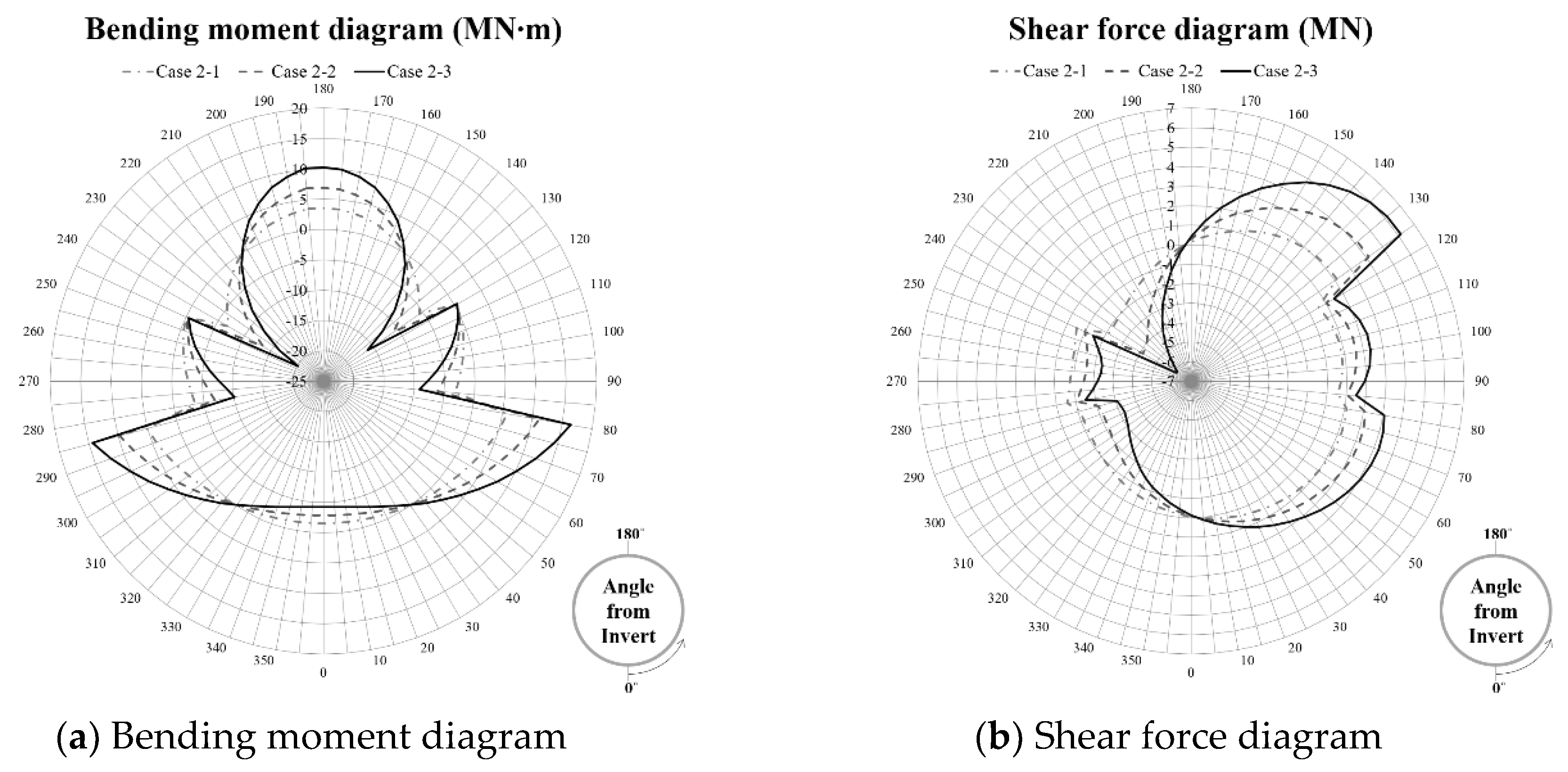
The change of member force depending on the depth of tunnel is investigated when the connection between intermediate slab and segment lining is fully fixed. Figure 7 presents the bending moment diagram and shear force digarm depending on the depth of tunnel. The shape of bending moment and shear force diagram does not change depending on the depth of tunnel. Maximum bending moment increases as the depth of tunnel increases: 5.82 MN·m (Case 2-1), 11.13 MN·m (Case 2-2), and 16.44 MN·m (Case 2-3), respectively. Maximum shear force increases as the depth of tunnel increases: −2.13 MN (Case 2-1), −4.14 MN (Case 2-2), and −6.14 MN (Case 2-3), respectively. It can be seen that the deeper the tunnel depth, the greater the member force of segment lining.

5.6. Effect of elastic modulus of ground

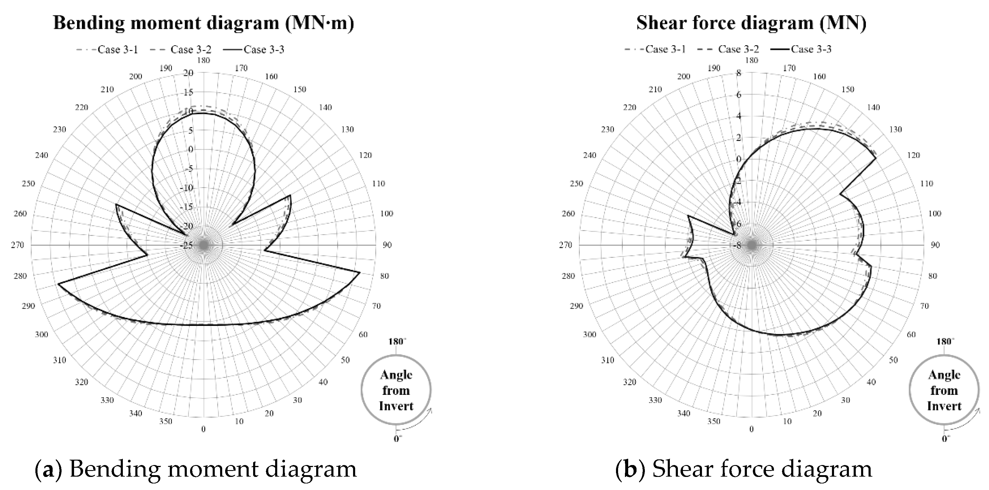
The change of member force depending on the elastic modulus of ground is investigated when the connection between intermediate slab and segment lining is fully fixed and the depth of tunnel is 30 m below the ground surface. Figure 8 presents the bending moment diagram and shear force digarm depending on the elastic modulus of ground. The ground stiffness was 3.52 MPa for Case 3-1, 7.04 MPa for Case 3-2, 10.56 MPa for Case 3-3, and the maximum bending moments are 16.29 MN·m, 16.44 MN·m and 16.44 MN·m and maximum shear forces are −6.36 MN, −6.15 MN, and −6.06 MN, respectively. Member force is not sensitive to the ground stiffness. Basically, the greater the stiffness of ground, the smaller the displacement after excavation and the smaller the force acting on the segment lining. Although the difference of bending moment is insignificant, the bending moment of smaller ground stiffness is smaller than that of higher ground stiffness. Beam–spring model doesn’t consider the excavation process and it only calculate the displacement of segment lining due to external load when the convergence due to excavation is fully completed. The effect of elastic modulus of ground on the structural behavior of segment lining should be examined with continuum analysis which can simulate the tunnel construction process better.

5.7. Effect of Traffic Load

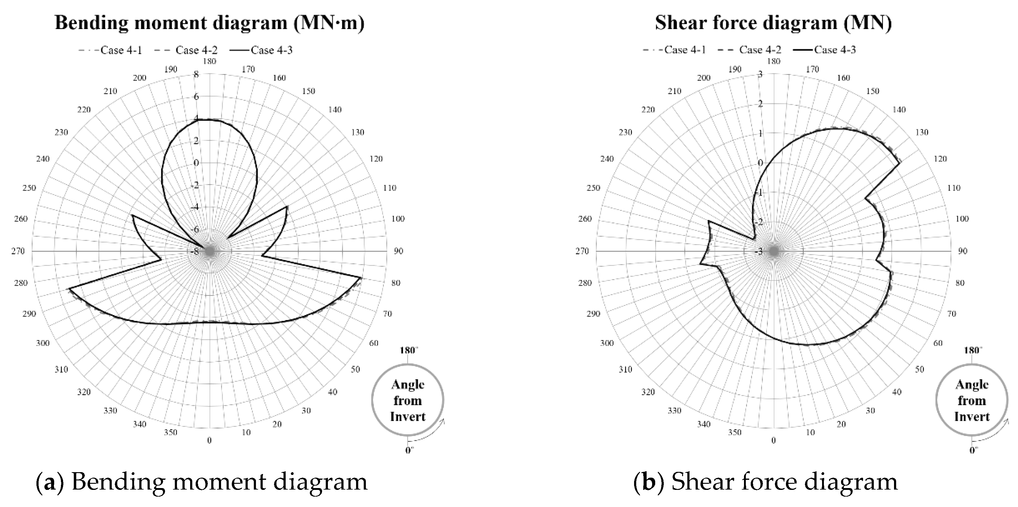
The change of member force depending on the traffic load is investigated when the connection between intermediate slab and segment lining is fully fixed and the depth of tunnel is 10 m below the ground surface. Figure 9 presents the bending moment diagram and shear force digarm depending on the elastic modulus of ground. Case 4-1 is DB-24, Case 4-2 is DB-18, Case 4-3 is DB-13.5. The maximum bending moments are 6.21 MN·m, 5.97 MN·m, and 5.79 MN·m and maximum shear forces are −2.30 MN, −2.24 MN and −2.20 MN, respectively. The smaller the traffic load, the smaller the bending moment and shear force. However, the impact of traffic load on member force is insignificant compared to other boundary conditions.

5.8. Effect of Connection Type on Intermediate Slab

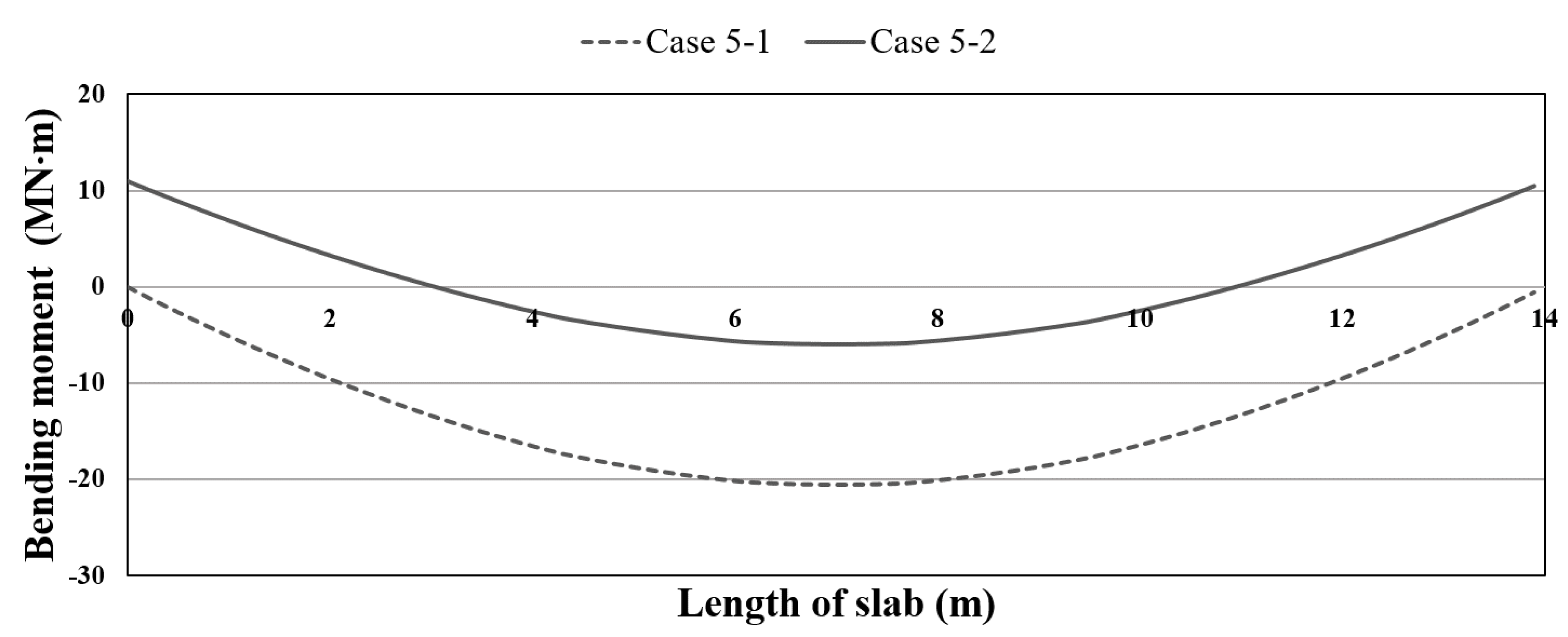
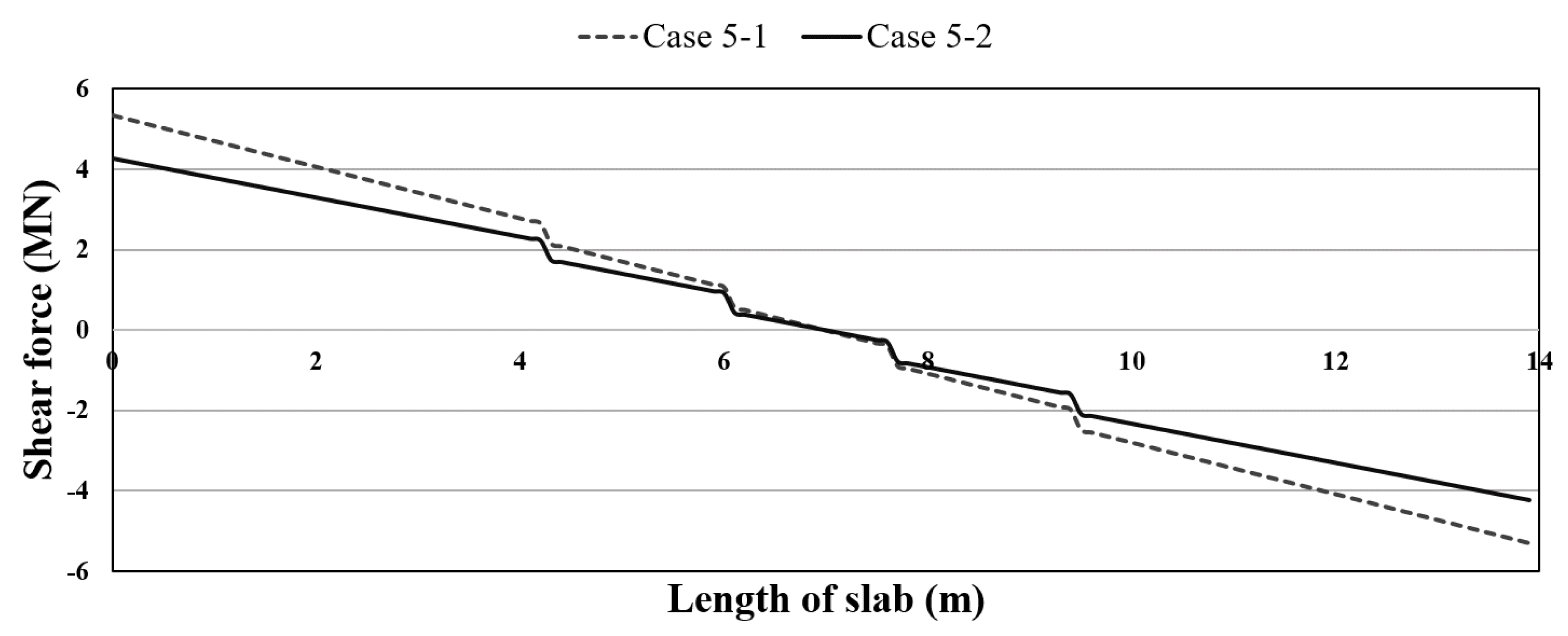
The member force of segment lining is a very important factor in the overall stability of the tunnel, but the intermediate slab has a great effect on the usability of a double-deck tunnel. Therefore, not only the member force, but also the effect of deflection on intermediate slab should be considered. The bending moment and shear force of intermediate slab is examined depending on the connection type. As it is tabulated in Table 8, simple connection type and fixed connection type are compared when traffic load is DB-24 and tunnel depth is 10 m. Figure 10 shows the bending moment diagram and Figure 11 shows the shear force diagram of upper intermediate slab. Bending moment and shear force of simple connection type are higher than those of fixed connection type.
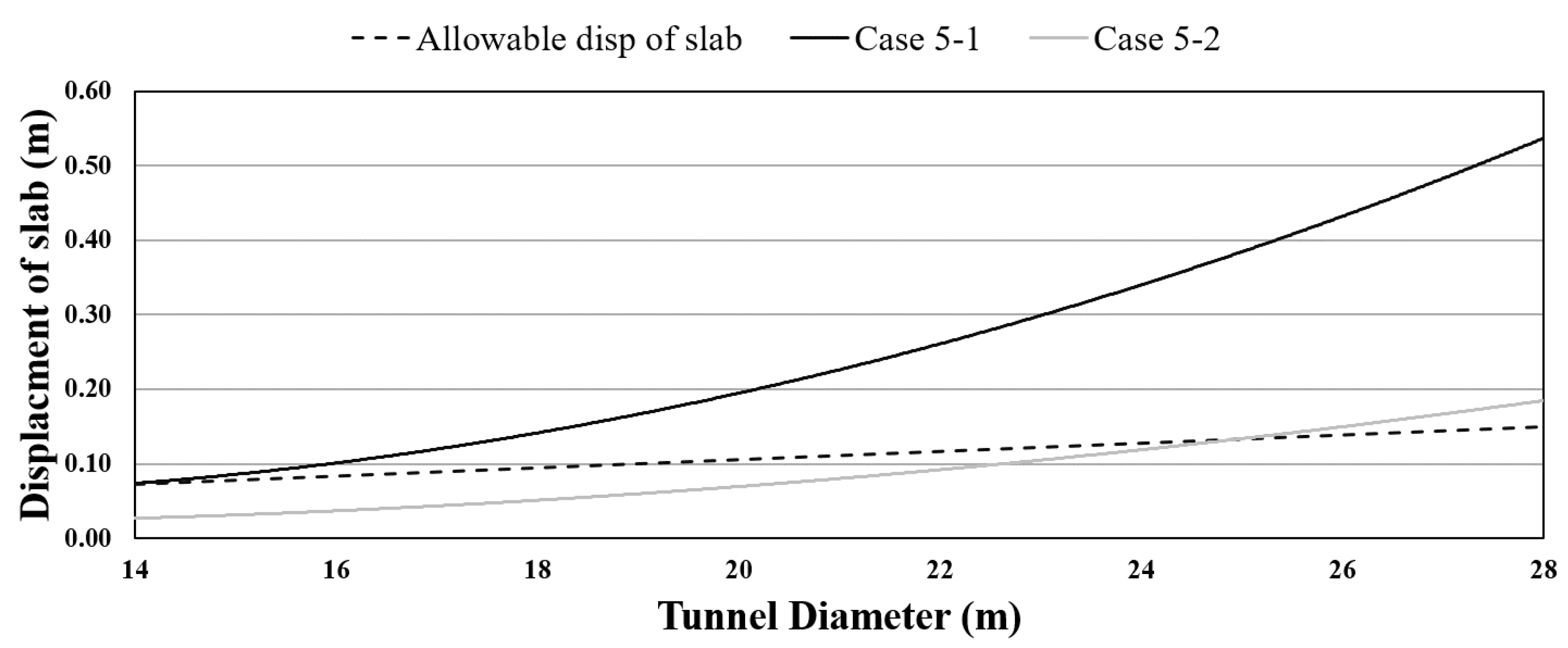
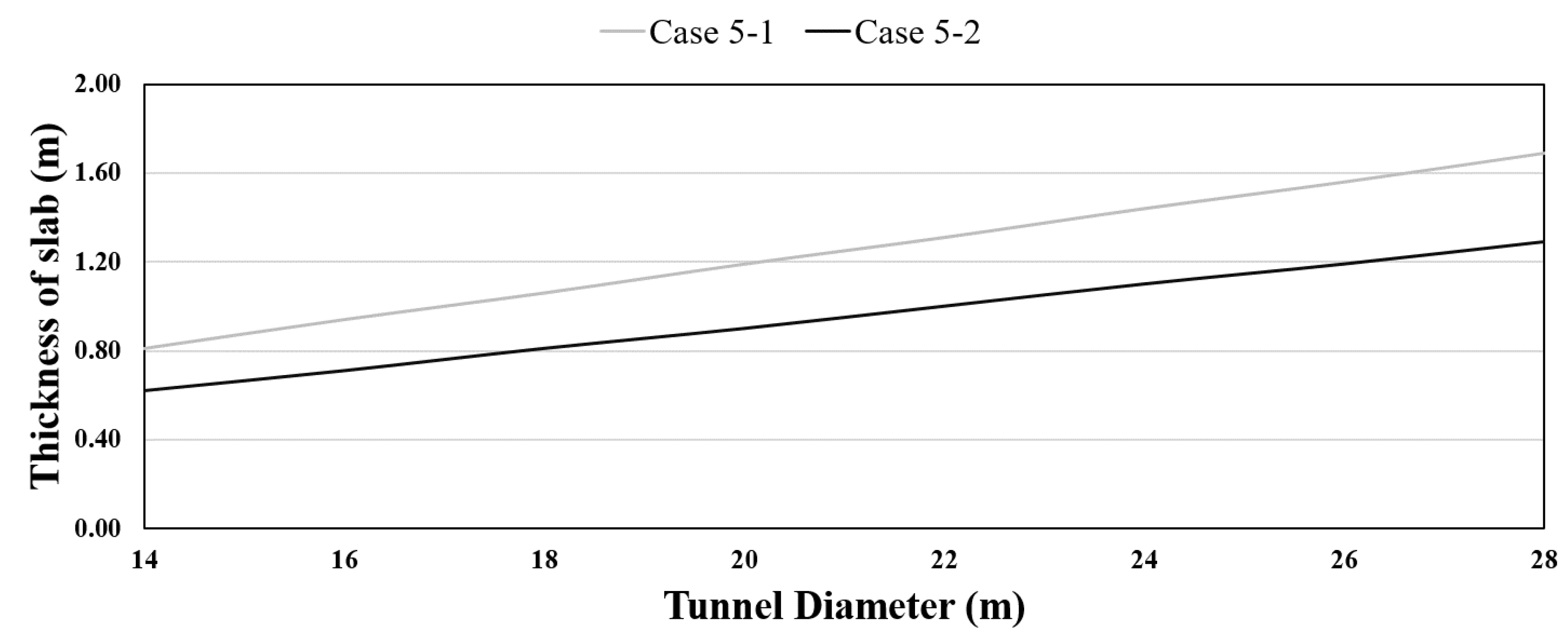
Figure 12 and Figure 13 show the deflection of slab and thickness of slab with respect to the tunnel diameter. Maximum displacement is calculated with the increase of intermediate slab length when the DB-24 of traffic load is imposed on top of slab. And, allowable displacement is determined based on the structural concrete design code [26]. As it is presented in Figure 12, when the intermediate slab is simply connected, slab displacement exceeds the allowable level as the tunnel diameter increases over 14 m. To reduce the slab displacement under allowable level, the thickness of slab should be increased, and it increases construction cost. It finally can cause the structural instability of segment lining. In case of fixed connection type, bending moment and shear force are small compared to simple connection type. And thus, the long span slab is theoretically possible. When the intermediate slab is fixed, tunnel diameter can be increased up to 25 m with minimum slab thickness of 450 mm.
Minimum thickness of the concrete slab is calculated with the increase of intermediate slab length when the maximum displacement is less than allowable. Thus, minimum thickness of concrete slab (Tmin) for simple connection and for fixed connection type can be obtained with Equation (6).
T m i n =   { L / 16 ,   for   simple   connection   type L / 21 ,   for   fixed   connection   type
From the Figure 13, the thickness of slab should be increased as the tunnel diameter increases. In conclusion, fixed connection type is advantageous for intermediate slab in terms of member force as well as displacement. In the design stage, the stress acting on the segment lining and intermediate slab should be carefully examined depending on the connection type of intermediate slab. And, the section of segment lining and intermediate slab should be determined to accommodate the member force induced by boundary conditions such as earth pressure, traffic load, and so on.

6. Conclusions

The stability of a double-deck tunnel is mainly governed by the intermediate slab. In this study, a performance-based evaluation method of a double-deck tunnel is suggested as a three-dimensional matrix considering the life cycle of a double-deck tunnel. Moreover, the effects of connection type as well as depth of tunnel, ground stiffness, traffic load on structural behavior of tunnel were comprehensively investigated. Fourteen different cases were analyzed and member force such as bending moment and shear force of segment lining and intermediate slab were obtained. From the analysis, salient finding can be summarized as follow.
It was found that the connection type between the segment lining and the intermediate slab significantly affects the behavior of segment lining: simply connected condition causes lesser stress and moment than fully fixed condition. As the depth of tunnel increases, the member force of segment lining increases due to increase of earth pressure acting on the segment lining. As the tunnel depth increases, the influence of connection type on the structural stability of the double-deck tunnel becomes insignificant. It was found that the member force is not sensitive to the ground stiffness due to the limitations of the beam–spring model. Because the beam–spring model calculates the displacement of segment lining due to external load when the convergence due to excavation is fully completed, the effect of elastic modulus of ground on the structural behavior of segment lining can be better examined with continuum analysis. The smaller the traffic load, the smaller the bending moment and shear force. However, the impact of traffic load on member force is insignificant compared to other boundary conditions. The thickness of slab should be increased as the tunnel diameter increases. Fixed connection type is favorable for intermediate slab and simple connection type is advantageous for segment lining. Thus, in design stage, the section of intermediate slab and segment lining and its connection type should be carefully determined considering the boundary condition to accommodate the member force induced.
Author Contributions

K.-N.K. and S.-H.L. developed code. K.-I.S. designed the structure of code. L.L. and S.M. analyzed the data.

Funding

This research was supported by a grant (15SCIP-B105148-01) from the Construction Technology Research Program funded by the Ministry of Land, Infrastructure, and Transport of the Korean government. This research was also supported by the National Natural Science Foundation of China (No. 51504182, 51674188, 51874229, 51404191).

Acknowledgments

This research was supported by a grant (15SCIP-B105148-01) from the Construction Technology Research Program funded by the Ministry of Land, Infrastructure, and Transport of the Korean government. This research was also supported by the National Natural Science Foundation of China (No. 51504182, 51674188, 51874229, 51404191).

Conflicts of Interest

The authors declare no conflict of interest.

References

  1. Bobylev, N. Mainstreaming sustainable development into a city’s Master plan: A case of Urban Underground Space use. Land Use Policy 2009, 26, 1128–1137. [Google Scholar] [CrossRef]
  2. Sterling, R.; Nelson, P. City resiliency and underground space use. In Advances in Underground Space Development; ACUUS: Singapore, 2013. [Google Scholar]
  3. Kim, H.S.; Kim, H.M. A study on cross sectional characteristics and available area for using the lower space in TBM road tunnels. J. Korean Tunn. Undergr. Space Assoc. 2012, 14, 141–157. [Google Scholar] [CrossRef]
  4. Park, H.B.; Cho, Y.K.; Lee, Y.H.; Kim, S.M. Numerical Analysis of Middle Slab Behavior in Double-Deck Tunnel Considering Emergency Evacuation Space. Korea Concr. Inst. Conf. 2016, 28, 43–44. [Google Scholar]
  5. Lee, H.S.; Moon, H.K. Behavior of the segment lining due to the middle slab and the lateral pressure coefficient in duplex tunnel. Tunn. Undergr. Space 2016, 26, 192–200. [Google Scholar] [CrossRef]
  6. Lee, H.S.; Moon, H.K. Numerical study on the connection type of inner-slab in double deck tunnel. J. Korean Tunn. Undergr. Space Assoc. 2016, 18, 441–451. [Google Scholar] [CrossRef]
  7. Takano, Y.H. ITA (International Tunnelling Association) Working Group No. 2. Guidelines for the design of shield tunnel lining. Tunn. Undergr. Space Technol. 2000, 15, 303–331. [Google Scholar]
  8. Ahmet, G.C. Evaluation of Structural Analysis Methods Used for the Design of TBM Segmental Linings. Master’s Thesis, Middle East Technical University, Ankara, Turkey, 2010. [Google Scholar]
  9. Klar, A.; Marshall, A.M.; Soga, K.; Mair, R.J. Tunneling effects on jointed pipelines. Can. Geotech. J. 2008, 45, 131–139. [Google Scholar] [CrossRef]
  10. Lee, Y.J.; Kim, K.L.; Jeong, K.W.; Hong, E.J.; Kim, S.H.; Jun, D.C. A study on the design of shield tunnel lining in high water pressure condition. J. Korean Tunn. Undergr. Space Assoc. 2015, 17, 227–236. [Google Scholar] [CrossRef] [Green Version]
  11. Nikkhah, M.; Mousavi, S.S.; Zare, S.; Khademhosseini, O. Evaluation of structural analysis of tunnel segmental lining using beam-spring method and force-method (Case study: Chamshir water conveyance tunnel). Int. J. Min. Reclam. Environ. 2017, 8, 111–130. [Google Scholar]
  12. Hur, J.S.; Kim, S.R.; Hwang, J.D.; Seo, Y.W.; Jung, M.K. A study on the performance-based design methodology for tunnels through case study on the tunnel built by the prescribed design. J. Korean Tunn. Undergr. Space Assoc. 2013, 15, 415–429. [Google Scholar]
  13. Liu, L.; Fang, Z.; Qi, C.; Zhang, B.; Guo, L.; Song, K.I. Numerical study on the pipe flow characteristics of the cemented paste backfill slurry considering hydration effects. Powder Technol. 2019, 343, 454–464. [Google Scholar] [CrossRef]
  14. Chang, S.H.; Lee, G.P.; Choi, S.W.; Bae, G.J. State of the art of segment lining in shield tunnel and statistical analysis of its key design parameters. Tunn. Undergr. Space 2011, 21, 427–438. [Google Scholar]
  15. Seok, J.H.; Choi, L.; Oh, H.J.; Cho, Y.K.; Kim, S.M. Fundamental study to establish design requirements of middle slabs in double-deck tunnel. Korea Concr. Inst. Conf. 2015, 3, 269–270. [Google Scholar]
  16. Seok, J.H.; Park, H.B.; Cho, Y.K.; Choi, L.; Kim, S.M. Introduction of analytical model to establish design criteria for middle slab of double-deck tunnel. Korea Soc. Road Eng. 2015, 10, 69. [Google Scholar]
  17. Kwon, T.H.; Cho, G.C. Smart geophysical characterization of particulate materials in a laboratory. Smart Struct. Syst. 2005, 1, 217–233. [Google Scholar] [CrossRef]
  18. Kwon, T.H.; Cho, G.C. Evolution of compressional wave velocity during CO2 hydrate formation in sediments. Energy Fuels 2009, 23, 5731–5736. [Google Scholar] [CrossRef]
  19. Ta, X.H.; Yun, T.S.; Muhunthan, B.; Kwon, T.H. Observations of pore-scale growth patterns of carbon dioxide hydrate using X-ray computed microtomography. Geochem. Geophys. Geosyst. 2015, 16, 912–924. [Google Scholar] [CrossRef] [Green Version]
  20. Japan Society of Civil Engineers (JSCE). Japanese Standard for Shield Tunneling, 3rd ed.; JSCE: Tokyo, Japan, 1996. [Google Scholar]
  21. Do, N.A.; Dias, D.; Oreste, P.; Djeran-Maigre, I. A new numerical approach to the hyperstatic reaction method for segmental tunnel linings. Int. J. Numer. Methods Geomech. 2014, 38, 1617–1632. [Google Scholar] [CrossRef]
  22. Wood, A.M. The circular tunnel in elastic ground. Geotechnique 1975, 25, 115–127. [Google Scholar] [CrossRef]
  23. Bickel, J.O.; Kuesel, T.R.; King, E.H. Tunnel Engineering Handbook; Chapman and Hall: New York, NY, USA, 1996. [Google Scholar]
  24. US Army Corps of Engineering (USACE). Tunnels and Shafts in Rock, Engineering Manual 1110-2-2901; USACE: Washington, DC, USA, 1997.
  25. Ministry of Construction and Transportation. Bridge Design Specification; Ministry of Construction and Transportation: Seoul, Korea, 2010.
  26. Ministry of Construction and Transportation. Structural Concrete Design Code; Ministry of Land, Infrastructure and Transport: Seoul, Korea, 2016.
Figure 1. 3D information matrix for performance-based evaluation of a double-deck tunnel.
Sustainability 11 00201 g001
Figure 2. Connection type of intermediate slab: (a) simple-connection type; and (b) fixed-connection type.
Sustainability 11 00201 g002
Figure 3. Structural models for intermediate slab: (a) simple-connection model; and (b) fixed-connection model.
Sustainability 11 00201 g003
Figure 4. Calculation process of beam–spring model.
Sustainability 11 00201 g004
Figure 5. Cross-section of a double-deck tunnel.
Sustainability 11 00201 g005
Figure 6. Member force diagram of segment lining depending on the connection type of intermediate slab.
Sustainability 11 00201 g006
Figure 7. Member force diagram of segment lining depending on the depth of tunnel.
Sustainability 11 00201 g007
Figure 8. Member force diagram of segment lining depending on the elastic modulus of ground.
Sustainability 11 00201 g008
Figure 9. Member force diagram of segment lining depending on traffic load.
Sustainability 11 00201 g009
Figure 10. Bending moment diagram of intermediate slab depending on the connection type.
Sustainability 11 00201 g010
Figure 11. Shear force diagram of intermediate slab depending on supporting type.
Sustainability 11 00201 g011
Figure 12. Displacement of intermediate slab depending on supporting type.
Sustainability 11 00201 g012
Figure 13. Thickness of intermediate slab depending on supporting type.
Sustainability 11 00201 g013
Table 1. Performance requirements definition of double-deck tunnel.
PerformancesDefinitions
SafetyThe performance to withstand external loads and influencing factors expected to structural safety.
Usability/FunctionalityThe performance to determine whether the double-deck tunnel could be in usable level and perform a function role.
DurabilityThe performance to withstand deterioration such as neutralization, salt corrosion and erosion.
Table 2. Principal factors for performance-based evaluation of a double-deck tunnel in design phase.
PerformancesStructural ElementsPrincipal Factors
SafetyGround- Ground strength parameter- Groundwater condition
- Geological condition (ex. stratum and discontinuity of the ground)
Segment lining- Design load and strength- Connection method of segment
- Shape design pf segment
- Watertightness- Fire resistance
Backfill grout- Gap parameter- Injection material
- Injection timing and method- Injection pressure
Invert- Design load and strength- Thickness of slab
- Stability analysis depending on area below slab
Middle slab- Design load and strength- Thickness of slab
- Support method of both ends of slab
Usability/FunctionalityGround- Permeability coefficient- Groundwater condition
- Ground surface displacement
Segment lining- Deformation- Water stop rubber
Backfill grout- Watertightness of grout
Invert- Deflection of slab- Pavement on slab
- Design of drainage system- Vibration of slab
Middle slab- Deflection of slab- Pavement on slab
- Design of drainage system- Vibration of slab
DurabilityGround- Deterioration factors effect on concrete
Segment lining- Anti-crack Design for segment lining
- Concrete deterioration- Corrosion resistance of steel
- Watertightness
Backfill grout- Watertightness of grout
Invert- Concrete deterioration- Corrosion resistance of steel
- Anti-crack Design for Invert- Design of drainage system
Middle slab- Anti-crack Design for middle slab
- Concrete deterioration-Corrosion resistance of steel
- Design of drainage system- Design for supporting point
Table 3. Principal factors for performance-based evaluation of a double-deck tunnel in construction phase.
PerformanceStructural ElementsPrincipal Factors
SafetyGround- Over break
- Measurement of excavation progress status
Segment lining- Damage of segments by construction load
- Construction state of segments connection
- Prevention of segments step
Backfill grout- Injection quality of backfill grout
- Injection pressure of backfill grout
- Voids survey
Invert- Damage of invert by construction load
- Construction state of both ends of slab
Middle slab- Damage of middle slab by construction load
- Construction state of both ends of slab
- Check of construction state Elastic mat of bracket (uncoupled form)
Usability/FunctionalityGround
Segment lining- Damage of segments by construction load
- Water stop rubber construction state
Backfill grout- Construction state inspection of finish work of injection hole
Invert- Finish work of slab joint
- Check of interference between disaster prevention and maintenance facility
- Drainage system construction
- Road pavement construction quality
Middle slab- Finish work of slab joint
- Drainage system construction
- Road pavement construction quality
DurabilityGround
Segment lining- Finish work of interior
- Concrete cover check for rebar
Backfill grout- Backfill grout injection quality
- Prevention of backfill grout loss by underground water flow
Invert- Finish work of invert
- Concrete cover condition check for rebar
Middle slab- Finish work of middle slab
- Concrete cover condition check for rebar
Table 4. Principal factors for performance-based evaluation of a double-deck tunnel in maintenance phase.
PerformanceStructural ElementsPrincipal Factors
SafetyGround- Measurement for maintenance
Segment lining- Measurement for maintenance
- Analysis of stress behavior caused by deformation
- Crack inspection for segment lining
- Fastening inspection for segment lining bolt
Backfill grout- Voids surveying beyond segment lining
Invert- Measurement for maintenance
- Joints inspection- Crack inspection
Middle slab- Measurement for maintenance
- Joints inspection- Crack inspection
- Elastic mat inspection of bracket
Usability/FunctionalitySegment lining- Measurement for maintenance
- Crack inspection for segment lining
- Leakage inspection
Backfill grout- Leakage inspection through injection hole
Invert- Measurement for maintenance
- Road pavement inspection
- Joints inspection- Crack inspection
- Inspection for Disaster prevention and maintenance facility
Middle slab- Measurement for maintenance
- Road pavement inspection
- Joints inspection- Crack inspection
- Elastic mat inspection of bracket
DurabilitySegment lining- Crack inspection for segment lining
- Corrosion inspection for rebar
- Concrete deterioration inspection
Middle slab- Leakage inspection through injection hole
Invert- Corrosion inspection for rebar
- Concrete deterioration inspection
- Drainage system inspection
Middle slab- Corrosion inspection for rebar
- Concrete deterioration inspection
- Drainage system inspection
- Elastic mat inspection of bracket
Table 5. Material properties of segment lining and intermediate slab.
PropertiesValues
γ c o n c (Unit weight) 26   kN / m 3
E c o n c (Elastic modulus) 38.82   GPa
n (Number of segments) 8   EA
I (Moment of inertia) 1.519 × 10 2   m 4
I e (Moment of inertia of force transmission zone) 1.059 × 10 2   m 4
Table 6. Ground condition of numerical model.
PropertiesValues
γ g r o u n d (Unit weight) 19   kN / m 3
E g r o u n d
(Elastic modulus)
Case 3-1 3.52   MPa
Case 3-2 7.04   MPa
Case 3-3 10.56   MPa
ν (Poisson’s ratio) 0.33
K 0 (Lateral earth pressure coefficient at rest) 0.5
Table 7. Traffic load depending on the classes (adopted from Ministry of Construction and Transportation [25]).
Traffic Load ClassesTotal Weight (kN)Front Wheel Weight (kN)Rear Wheel Weight (kN)
DB-244322496
DB-183241872
DB-13.524313.554
Table 8. Analysis cases.
Case E g r o u n d   ( MPa ) Depth   ( m ) Traffic Load ClassesConnection Type of Intermediate Slab
3.527.0410.56102030DB-24DB-18DB-13.5No SlabSimpleFixed
1-1 О О О
1-2 О О О
1-3 О О О
2-1 О О О О
2-2 О О О О
2-3 О О О О
3-1О О О О
3-2 О О О О
3-3 О О О О
4-1О О О О
4-2О О О О
4-3О О О О
5-1О О О О
5-2О О О О