Article

Impact of an Ultraviolet Reactor on the Improvement of Air Quality Leaving a Direct Evaporative Cooler

1
Department of Architectural Engineering, Hanyang University, Seoul 04763, Korea
2
Department of Architectural Engineering, Sejong University, Seoul 05006, Korea
*
Author to whom correspondence should be addressed.
Sustainability 2018, 10(4), 1123; https://doi.org/10.3390/su10041123
Submission received: 17 March 2018 / Revised: 5 April 2018 / Accepted: 5 April 2018 / Published: 9 April 2018

Abstract

:
The purpose of this study is to improve microbial air quality by improving water quality, particularly concerning microbiological aspects, by applying an ultraviolet water purifier system to a direct evaporative cooling (DEC) system. A direct evaporative cooler is an air cooling technique that uses the evaporation of water. Most DECs recirculate water to reduce water use. Evaporative cooling pads and water are biologically contaminated by recirculating water. This contamination can develop into air contamination and cause respiratory illnesses in occupants. It is necessary to use sterilized water in a DEC to prevent respiratory diseases and maintain air quality. In this study, we examine whether improvements in water quality in a DEC affect air quality by dividing experiments into a control group (Control) and a treated group (UV-treated). In the control group, the degree of contamination was measured when a DEC operated for four weeks without ultraviolet water treatment. In UV-treated, the degree of contamination was measured when UV water treatment was applied to a DEC for four weeks. In both Control and UV-treated, microbes were sampled from the water, the evaporative cooling pad surface, and the DEC inlet and outlet air samples in order to compare the levels of contamination. The surface was measured once at four points, and the air was measured four times at two points. A comparison of the two experiments indicated that the degree of microbial contamination of water and air was significantly reduced in the UV-treated group when compared to that in the control group. When the pollution degree of the evaporative cooling pad was compared to the degree of air pollution, it was difficult to obtain a correlation between the two factors, although the results confirmed that the contamination of the evaporative cooling pad caused water pollution. Therefore, it is necessary to operate a water treatment system to maintain the clean air in DECs.

1. Introduction

Evaporative cooling technology is a non-vapor compression heating, ventilating, and air conditioning (HVAC) technology that is used as to simultaneously induce the adiabatic cooling of process air with the evaporation of water by performing a heat exchange with water and process air [1]. Several studies focus on environmentally-friendly technology that cools the air without using refrigerants [2,3,4,5]. One of these evaporative cooling technologies is an indirect evaporative cooler (IEC), which consists of two channels of plastic material: On the secondary air channel, adiabatically cooled air exchanges sensible heat with process air and on the primary air channel, cools the process air. Another one of these technologies is a direct evaporative cooler (DEC), which is a device that induces adiabatic cooling by passing air through an evaporative cooling pad of wet cellulosic material. Finally, indirect-direct evaporative cooler (IDEC) uses IEC and DEC collectively and is a typical evaporative cooling technology [6].
A cooling tower and an evaporative condenser form a system that chills cooling water by using evaporative cooling, based on a principle similar to a DEC. It is necessary for the cooling tower, evaporative condenser, and a DEC to provide sufficient water to facilitate adiabatic evaporation. Water is recirculated in most systems to reduce water consumption. However, recirculating water used in cooling towers and evaporative condensers leads to the accumulation of microbial contamination. This type of contamination causes respiratory diseases such as Legionnaires’ disease and may result in casualties [7,8,9]. Legionella bacteria were observed in a dehumidification system by using a lithium chloride solution, according to a principle similar to that of a direct evaporative cooling system [10].
Legionnaires’ disease occurs when water-borne Legionella pneumophila bacteria are transferred by aerosols and adhere to the lungs. The functioning of direct evaporative coolers is similar to that of cooling towers and evaporative condensers. However, there has been no known outbreak of Legionnaires’ disease through direct evaporative coolers. This is potentially due to two main reasons. The first is temperature conditions in which it is difficult to activate Legionella bacteria. Cooling towers and evaporative condensers exhibit higher water temperatures when compared to those in a DEC during operation. Most DECs operate at water temperatures of 20–24 °C. Legionella bacteria do not multiply in a dormant state at temperatures below 20 °C and are active at 20–45 °C [11]. Therefore, it is difficult to proliferate Legionella bacteria in a direct evaporative cooling system (DEC). In areas requiring direct evaporative cooling, the wet bulb temperature is below 25 °C. In DEC, the wet bulb temperature of inlet process air, dry bulb temperature of outlet process air, and temperature of recirculating water are almost equal, thus the DEC is operating at a temperature at which Legionella does not reproduce [12].
The second reason is that the droplet size in a direct evaporative cooler is very low. The size of Legionella is 0.3–0.9 μm wide and 2–20 μm long. For Legionella to stick to the lungs, it must enter the lungs through droplets with a diameter less than 5 μm (i.e., aerosol). The size of water droplets produced by the direct evaporative cooler differs based on the type of evaporator, however; small water droplet evaporates and the larger is difficult to stick to lungs [13].
Legionnaires’ disease is unlikely to occur due to the operation temperature range and the droplet sizes in a DEC. However, temperature varies within an annual HVAC system, and other microbes in addition to Legionella also lead to air pollution [14].
Several researchers have confirmed that water contamination by microorganisms diffuses into the air and causes pollution in a DECs. Macher and Girman [15] measured the microbial contamination of a sump, indoor air, and outdoor air when DECs was used, and confirmed a correlation between sump contamination and indoor air quality. Strindehag and Josefsson [16] compared the bacterial counts of humidified air released from a spray type humidifier and an evaporative humidifier in experiments and simulations that added Pseudomonas aeruginosa to water. Macher et al. [17] used tracer bacteria (i.e., Micrococcus luteus) to determine the number of microorganisms detected in the discharge air based on the microbial air volume.
The United States Environmental Protection Agency has registered several water biocides to control algae, slime, and bacteria growth in cooling towers, air washers, and evaporative condensers. However, when water biocides are used in DECs, hazardous residual gases and by-products generated by the biocide enter spaces in conjunction with the process air, and this is hazardous to occupants [6]. Therefore, various methods were examined to solve the problem.
Several studies focused on efforts to prevent contamination of DEC outlet air. Kang and Kato [18] experimented with microwave disinfection of elements in an evaporative humidifier (EH) by using Legionella’s germicidal effect temperature characteristics (it is difficult for Legionella to survive at temperatures exceeding 60 °C). The EH pad was heated to 60 °C for 12 min without a blower and water spray. However, the results confirmed that temperature distribution was irregular, irrespective of wetness, and was not suitable for disinfecting an EH pad. Sung et al. [19] experimented with UV lamps and a water filter to suppress microbial growth of EH. The results confirmed that the microorganisms on the surface of the element, microorganisms inside the air handling unit (AHU), and pollutants in the recirculating water were significantly reduced when an ultraviolet sterilizer was used, although the internal microorganisms of the element were not removed. It is also difficult to disinfect an EH pad surface by using a UV lamp or a microwave. Additionally, degradation may occur after a certain period of time and cause defects in the equipment.
UV reactors are specifically used to treat drinking water, wastewater, industrial process water, and ballast water by exposing flowing water to the light of a UV lamp, thus inactivating the microorganisms in water. There is no residual effect, and chemicals are not added once the water leaves the UV reactor [20]. Yamamoto et al. [21] confirmed the killing rate of Legionella, based on a dose of UV light when a UV sterilizer generating a wave length of 254 nm was used. The results of the experiments confirmed that a UV sterilizer could be used to control Legionella in a cooling tower.
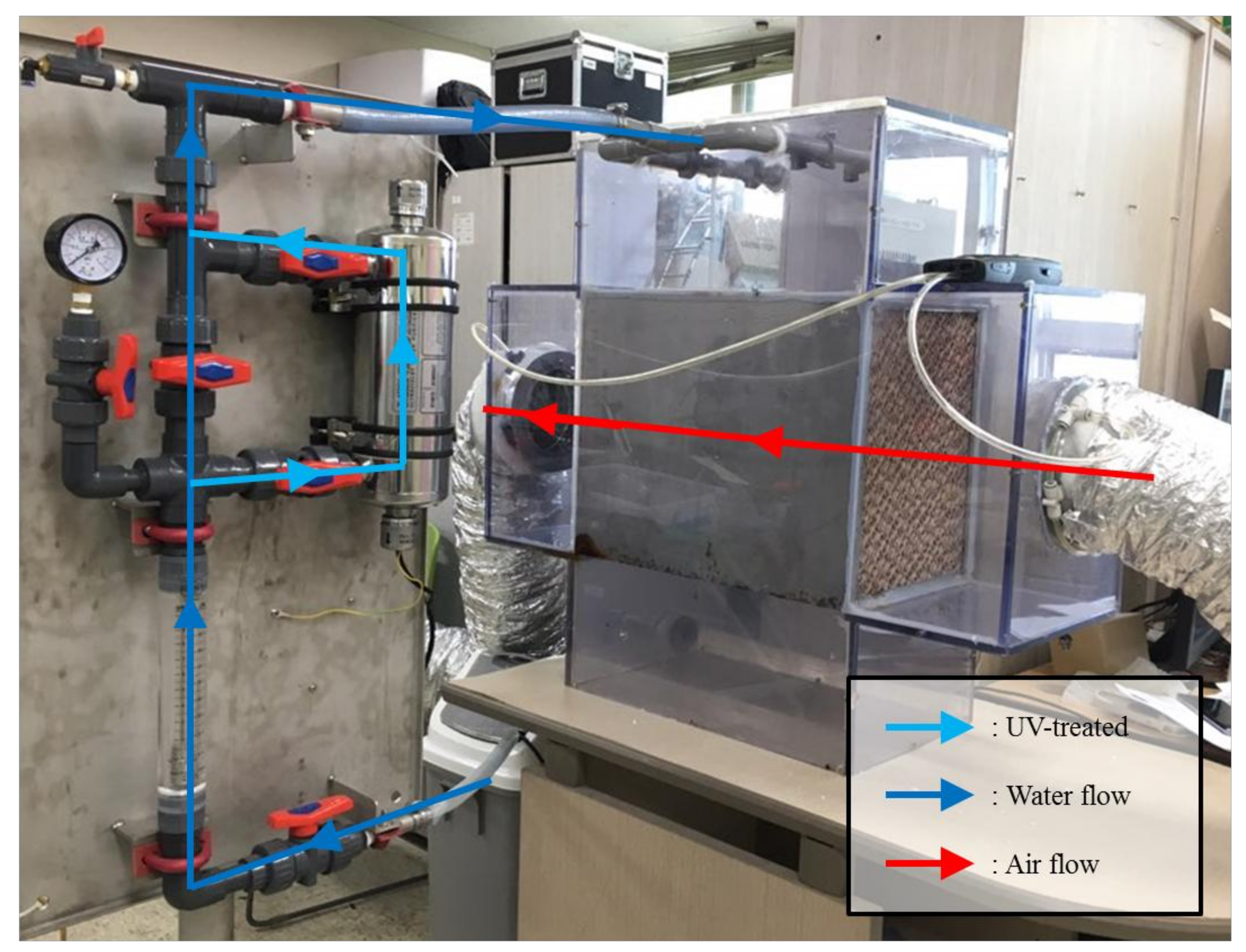
In this study, the experiments confirmed that the microbial contamination of a DECs improved when the disinfected water was supplied to the direct evaporative cooling system using a UV reactor.

2. Experimental Methods

2.1. System Overview

The system consists of an environmental chamber, DEC, a recirculation pump, a sump, a UV reactor, and a fan, as shown in Figure 1.
The process air was pre-filtered and conditioned in an environmental chamber and supplied to the DEC. The air temperature and humidity conditions of the environmental chamber were set as dry bulb temperature (DBT) 30 °C and wet bulb temperature (WBT) 20 °C based on the DEC experiment recommended range in ASHRAE [22].
The evaporative cooling pad (CELdek® 7060-15, Munters, Stockholm, Sweden) had a corrugated shape, and the material was composed of cellulose. The evaporative cooling pad size was 300 mm × 400 mm × 500 mm. There were four nozzles that supplied water to the DEC, which sprayed water at 120°. The size of the sump was 40 L, and this was responsible for the water usage per day without make-up water.
The UV reactor was a typical commercial UV sterilization system (Min-3), with a UV lamp that irradiated and sterilized running water. Specifically, Min-3 provided an ultraviolet dosage exceeding 30,000 μWs/cm2 during the operation. The system was sufficient for water treatment given that the ultraviolet dosage required for 99% inactivation of L. pneumophila and Bacillus subtilis spores is 12,300 and 22,000 μWs/cm2, respectively. In the experiment, the piping of the UV reactor was designed in two ways. The valve was adjusted to pass or bypass the UV reactor. Figure 2 shows the direct evaporative cooling system combined with the UV reactor, as well as the piping configuration. Detailed specifications for the UV reactor are shown in Table A1.

2.2. System Operation Method

The system operated from 9:00 a.m. to 6:00 p.m. on weekdays, according to the occupancy schedule of ASHRAE 90.1 [23]. As recommended in the ASHRAE guidelines, the water used for the DEC was drained after a day of operation and fresh water was used on the next day. To reduce microbial growth in the evaporative cooling pad, the pad had to remain dry while the DEC was not in operation. Therefore, the recirculation pump was turned off and the fan was turned on for 30 min after the system operation was finished [12].

2.3. Sampling Method

Experiments were divided into a control group not using a UV reactor (Control) and an experimental group using a UV reactor (UV-treated). Table 1 shows the number of sampling times and sampling points during the operation periods in the Control and UV-treated experiments.
Both the Control and UV-treated cases involved sampling air, water, and surface twice a week for four weeks. The sampling positions based on the sample objects are shown in Figure 3.
Evaporative cooling pads, nozzles, and pipes were sterilized with hydrogen peroxide water two days before the experiment to ensure that the conditions for Control and UV-treated cases were identical.

2.3.1. Water Sampling

A sample cock was installed to sample the water supplied to the DEC. The sample cock was sterilized with alcohol to prevent cross-contamination during water sampling. The sample cock was opened, 1 L of water was drained, and water was sampled from the sample bottle. In UV-treated cases, the water treated by the UV reactor and the bypassed water were separately sampled by using the valve control.

2.3.2. Surface Sampling

There are several methods to collect surface microorganisms (such as the Rodac plate method, the tape lift method, and the swab method). However, the Rodac plate method and the tape lift method are not suitable for sampling corrugated evaporative cooling pads. In the experiment, swabs were inserted into the wrinkled holes to sample internal microorganisms. There was one sampling point at the inlet and outlet of the evaporative cooling pad, respectively, and two points at the top of it. Inlets and outlets were measured at specific holes at a height of 35 cm from the bottom of the evaporative cooling pad.

2.3.3. Air Sampling

An impactor air sampler (i.e., BUCK BioCulture Model B30120 [24]) was used to detect microorganism contaminants in the process air. The specifications of the air sampler are summarized in Table 2.
The calibration of the air sampler was performed for every experiment to improve the accuracy of microbial counting. At the sampling time, the sample should not have been affected by air other than process air. In the experiment, an acrylic chamber was installed in the flexible duct upstream and downstream of the DEC. Air sampling was measured in an installed acrylic chamber. The size of the acrylic chamber was 20 cm × 20 cm × 25 cm. Prior to sampling, the disinfectant (ethanol, 70% volume fraction) was sprayed onto the acrylic chamber and air sampler to prevent cross-contamination. Four agar plates (with two different sampling times that were analyzed in parallel) were used per sample. The fungi and bacteria of the inlet and outlet air were simultaneously sampled (Figure 1 and Figure 3) [25,26]. The sampling time of the air sampler were set as 1 min and 2 min for bacteria and as 1 min, 2 min, and 5 min for fungi.
Samples (agar plate, water, cotton swab) were maintained below 25 °C to prevent growth after sampling. In the experiment, the samples were stored in insulated and refrigerated containers during transfer to the incubator. Table 3 shows the sampling and culture methods of bacteria and fungi in air, water, and on the surface.

3. Results

The DEC operated for eight weeks under the conditions listed in Table 4. The direct saturation effectiveness of the DEC was derived by Equation (1) as follows:
ε D E C = 100 × D B T i n D B T o u t D B T i n W B T o u t

3.1. Water Bio-Contamination

Bacterial contamination of recirculating water was measured by dividing it into three types of samples as follows: The first water sample was the water collected from the sump (in Control, not UV-sterilized), the second water sample was the water collected through the evaporative cooling pad (in UV-treated, it was UV-sterilized and sampled at the outlet of the evaporative cooling pad), and the third water sample was the water collected prior to passing through the evaporative cooling pad (in UV-treated, it was UV-sterilized and sampled before passing through the evaporative cooling pad). There were significant variations in the bacterial contamination of recirculating water in the first, second, and third water samples. The first and second water samples were cultured and the bacteria counts were obtained from the 104 dilutions because the contamination was high. In the third water sample that was passed through the ultraviolet reactor, the contamination was relatively low, and it was cultured after it was diluted twice. Figure 4 shows the bacterial contamination counts for the three types of water samples during the operation of the DEC.
As shown in Figure 4, the number of colonies per 1 mL of the first water sample was approximately 3 to 43 times that of the second water sample. The second water sample was 1.1 to 480 times that of the third water sample. Water-borne bacteria colonies in the 3-1 Control case accidently decreased. This could be because the running water, which was outside of our control, was used in every experiment. This could mean that the temperature and quality of the water could have varied and influenced this result.

3.2. Surface Bio-Contamination

In both Control and UV-treated cases, the results confirmed that the surface microbial contamination of the evaporative cooling pad during the operation of the DEC. Figure 5 and Figure 6 are graphs that show the average number of bacterial and fungal colonies sampled at four sites on the evaporative cooling pad for four weeks.
Based on the surface microbial contamination data of the Control and UV-treated samples, we confirmed the correlation between ultraviolet water treatment and surface microorganisms by performing a t-test. In the case of bacteria, the average contamination in Control samples was 182.7, and the average contamination in UV-treated cases was 157.2. Control cases displayed 25.5 times the contamination of UV-treated samples, although this was not statistically significant (p-value = 0.602). However, in the case of fungi, the average contamination in Control cases was 237.9, and the average contamination in UV-treated cases was 81.7. Control cases displayed 156.2 times the contamination of UV-treated samples, and this was statistically significant (p-value = 0.033). This indicates that the degree of surface microbial contamination due to water quality improvement is more sensitive in fungi when compared to bacteria.

3.3. Airborne Bio-Contamination

To confirm the air quality improvement effect of a UV reactor in the DEC, we used a bio-contamination sampler with TSA and PDA to sample the bacteria and fungi in the inlet side and outlet side of the DEC. To compare the pollution degree (F) to the inlet air and outlet air in the DEC, a colony-forming unit (CFU) extracted from four agar media was converted by Equation (1) as follows:
F = N T
Table 5 summarizes the bacterial contamination measurements of process air at the inlet and outlet of the DEC when recirculated water bypassed the UV reactor (Control). The air supplied to the DEC exhibited a very low level of bacterial contamination, although the air was observed as highly contaminated with bacteria after passing through the DEC.
Table 6 summarizes the bacterial contamination measurements of process air at the inlet and outlet of DEC when the recirculation water was sterilized by a UV reactor (UV-treated). As observed in the Control case, the air supplied to DEC in UV-treated samples exhibited low bacterial contamination, although the outlet air increased bacterial contamination after passing through DEC. However, the bacterial contamination levels shown in the outlet column of Table 6 indicates a significant reduction in the number of bacterial populations compared to those of Table 5.
Table 7 summarizes fungal contamination measurements of the process air at the inlet and outlet of the DEC when the recirculated water bypassed the UV reactor (Control). The air supplied to the DEC exhibited very low fungal contamination, although the air after passing through the DEC was observed as highly contaminated with bacteria and fungi. A PDA is an agar that is used to extract fungi. However, excessive amounts of bacteria were released from DEC and interfered with fungal growth in the PDA.
Table 8 summarizes fungal contamination measurements of the process air at the inlet and outlet of the DEC when the recirculation water was sterilized through a UV reactor (UV-treated). As observed in the Control case, both bacteria and fungi were also collected in the PDA of UV-treated samples. In the Control and UV-treated cases, it was difficult to pinpoint the fungus sample value due to bacterial influences on the PDA, although both bacterial and fungal contamination levels shown in the outlet column of Table 8 indicate a significant decrease compared to those of Table 7. As a result, microbial air quality improved when the recirculated water was treated by a UV reactor.

4. Discussion

Puckorius et al. [13] reported that Legionella spp. is difficult to cultivate or transfer because of the system temperature and size of water droplets in a direct evaporative cooling system. However, Macher and Girman [15] and Strindehag et al. [16] have confirmed several microbial contaminations of outlet air due to microbial contamination of recirculating water in a direct evaporative cooling system.

4.1. Impact of UV Light

Sung et al. [19] proposed a germicidal system, installing a UV lamp upstream and downstream of the evaporative humidifier (EH) pad and applying a UV water filter to the circulating water. When the proposed germicidal system was used, the bacteria and fungi decreased significantly on the EH pad surface. Microbial contamination of the circulating water was also reduced. In the case of airborne microbes in the air handling unit, it was confirmed that the bacteria decreased significantly, but the fungi maintained a constant degree of contamination. In a study by Sung et al., microbial contamination of outlet air was not measured. However, the proposed germicidal system improved the air quality of the outlet air when contamination of the outlet air was deduced from the pollution degree of the suspended microorganisms measured in the AHU.

4.2. Impact of UV Reactor

The germicidal system proposed by Sung et al. [
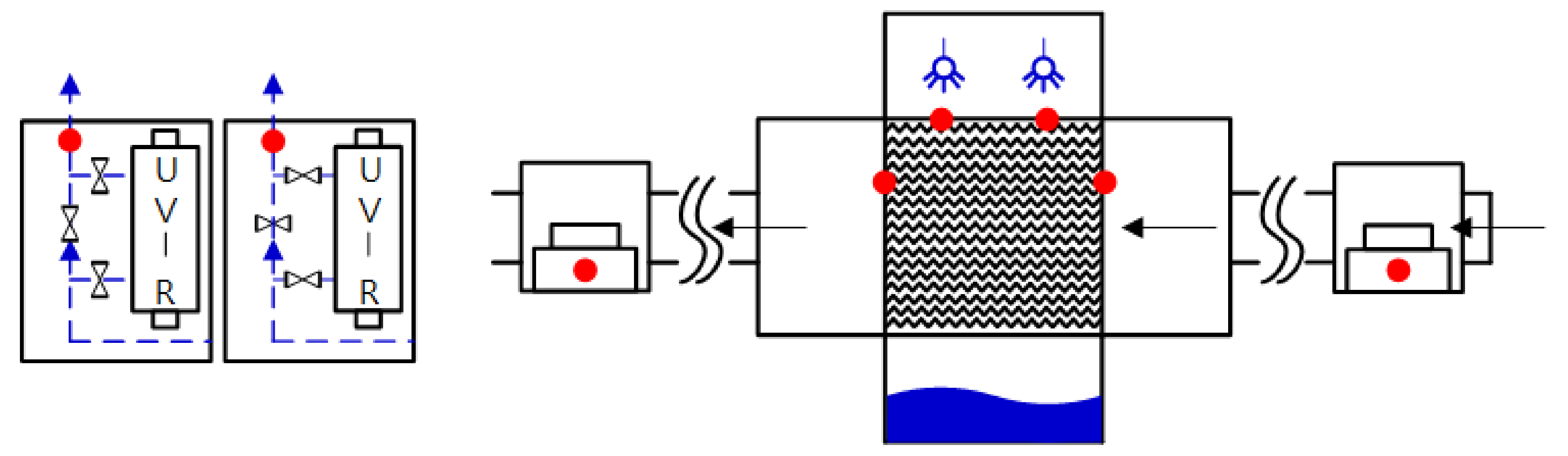
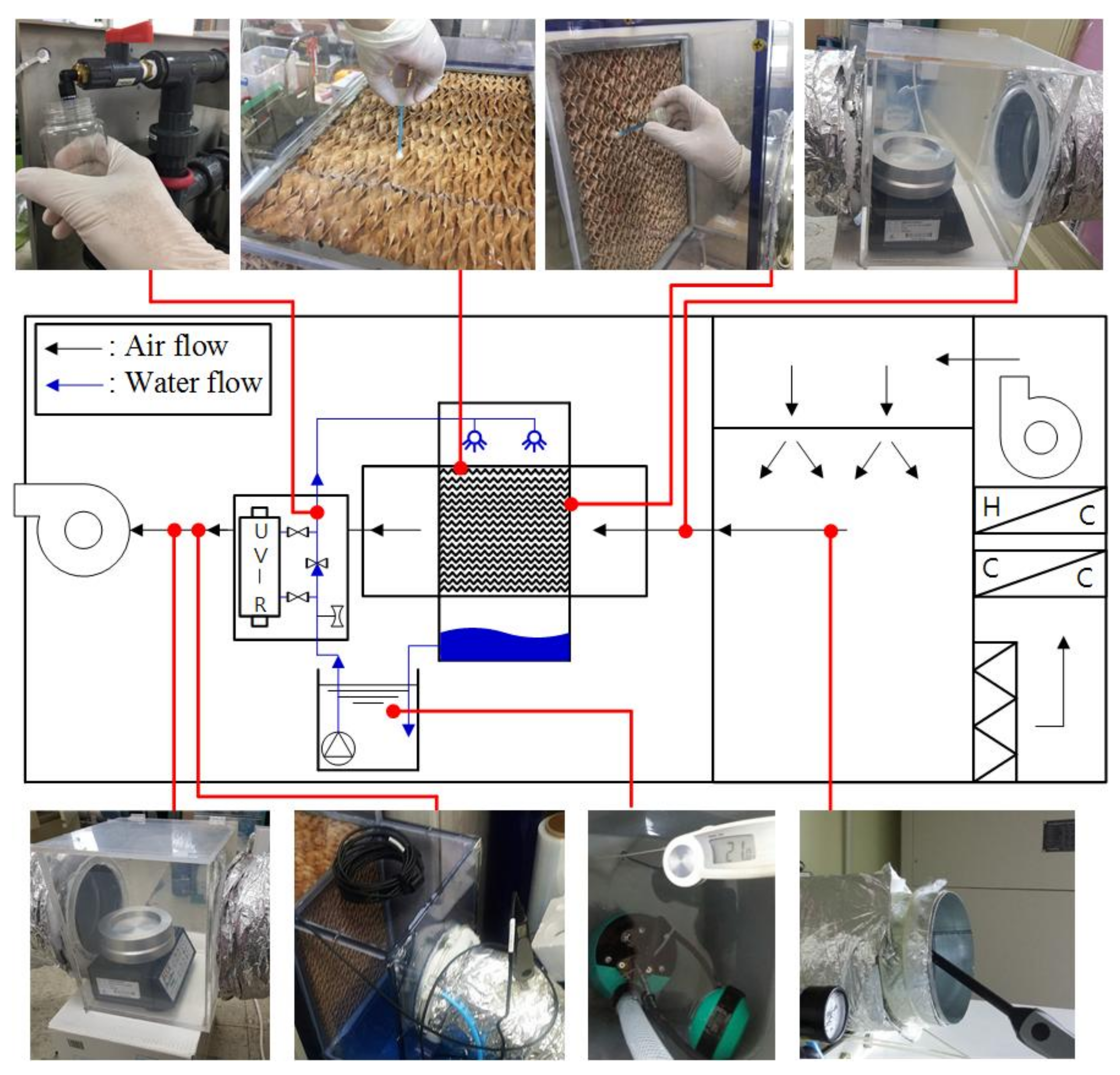
19] improved the internal air in the EH system. The germicidal system consisted of two components, a UV lamp that disinfected the pad surface and air, and a UV water filter which disinfected recirculating water. Therefore, it is unclear what the cause of air quality improvement of outlet air in the AHU was. In this study, two cases were tested based on the assumption that water pollution affects air quality through analysis of previous research (Control and UV-treated). The results of the study are as follows.
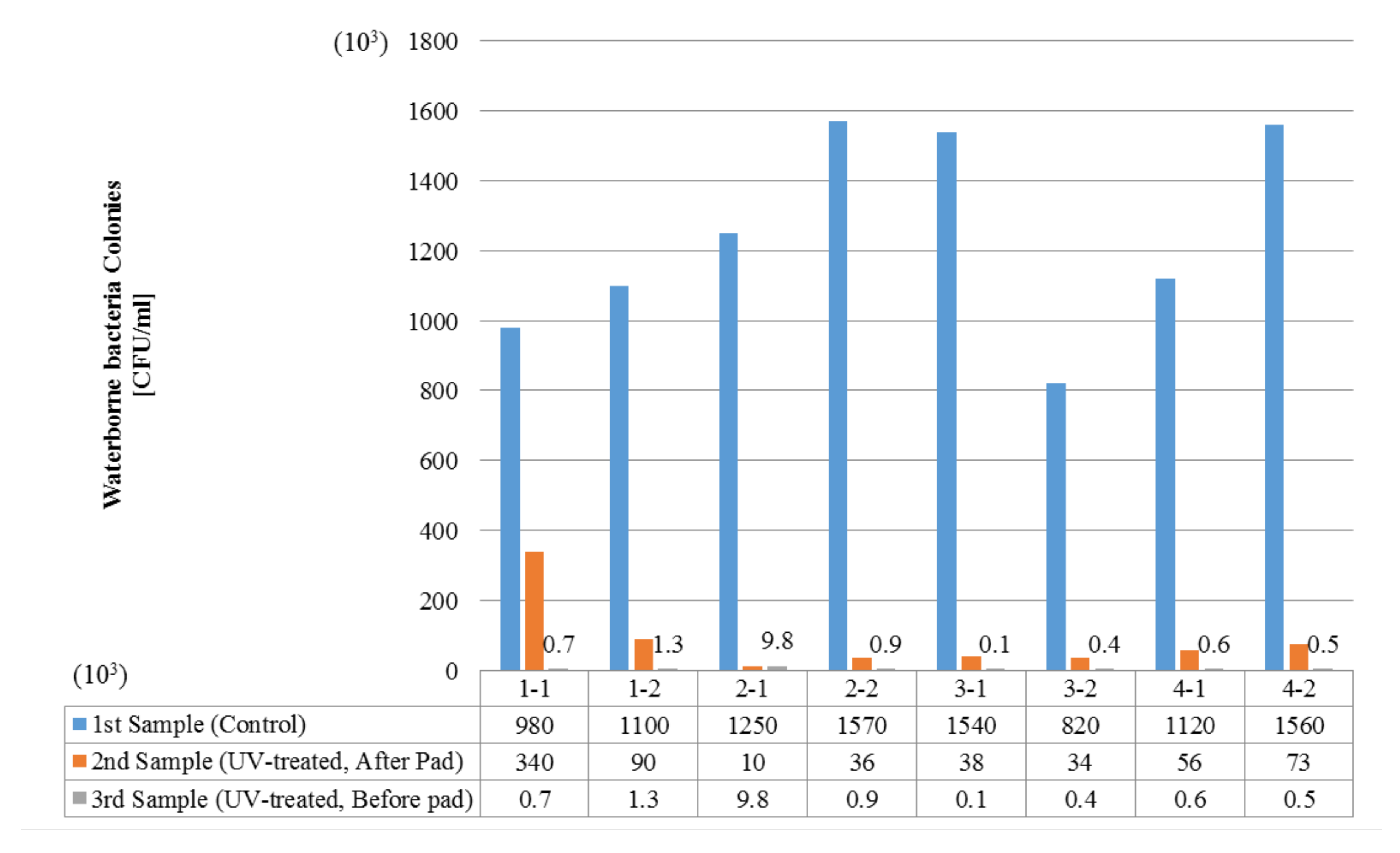
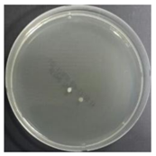
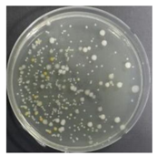
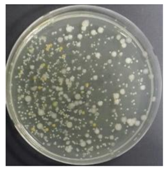
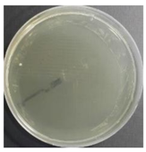
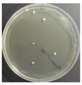
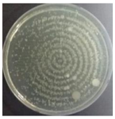
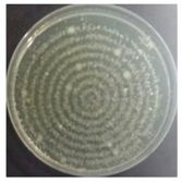
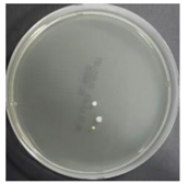
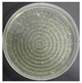
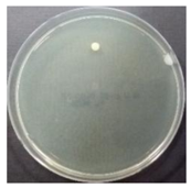
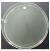
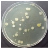
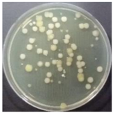
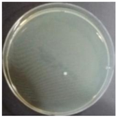
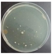
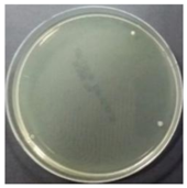
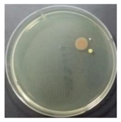
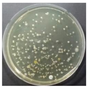
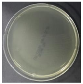
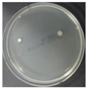
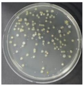
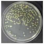
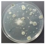
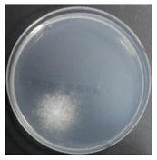
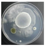
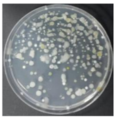
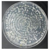
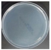
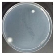
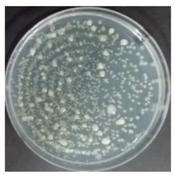
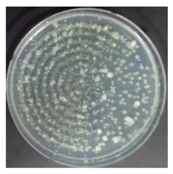
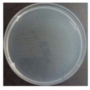
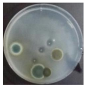
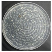
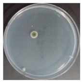
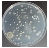
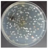
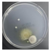
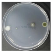
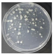
In the absence of a UV reactor in the direct evaporative cooling system (Control), bacterial concentrations in the recirculated water showed high concentrations (820,000–1,570,000 CFU/mL) in the AC film. In the direct evaporative cooling system with ultraviolet disinfection (UV-treated), the recirculated water had a low contamination level (100–700 CFU/mL) immediately after disinfection. However, after the disinfected water passed through the evaporative cooling pad, it was confirmed that the contamination increased (1000–340,000 CFU/mL). This suggests that bacteria accumulated in the evaporative cooling pad and pipe, increasing the contamination of recirculating water.
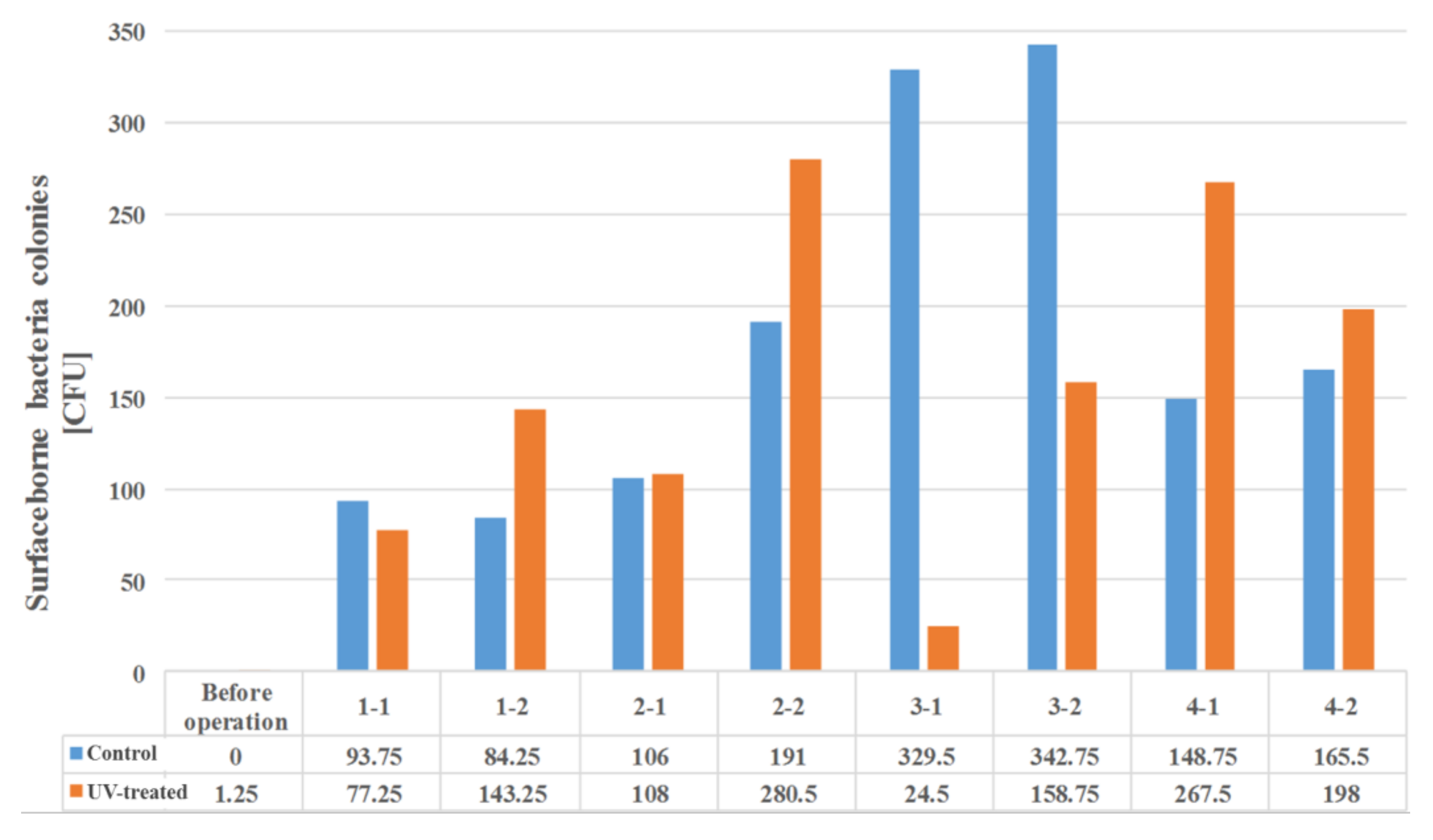
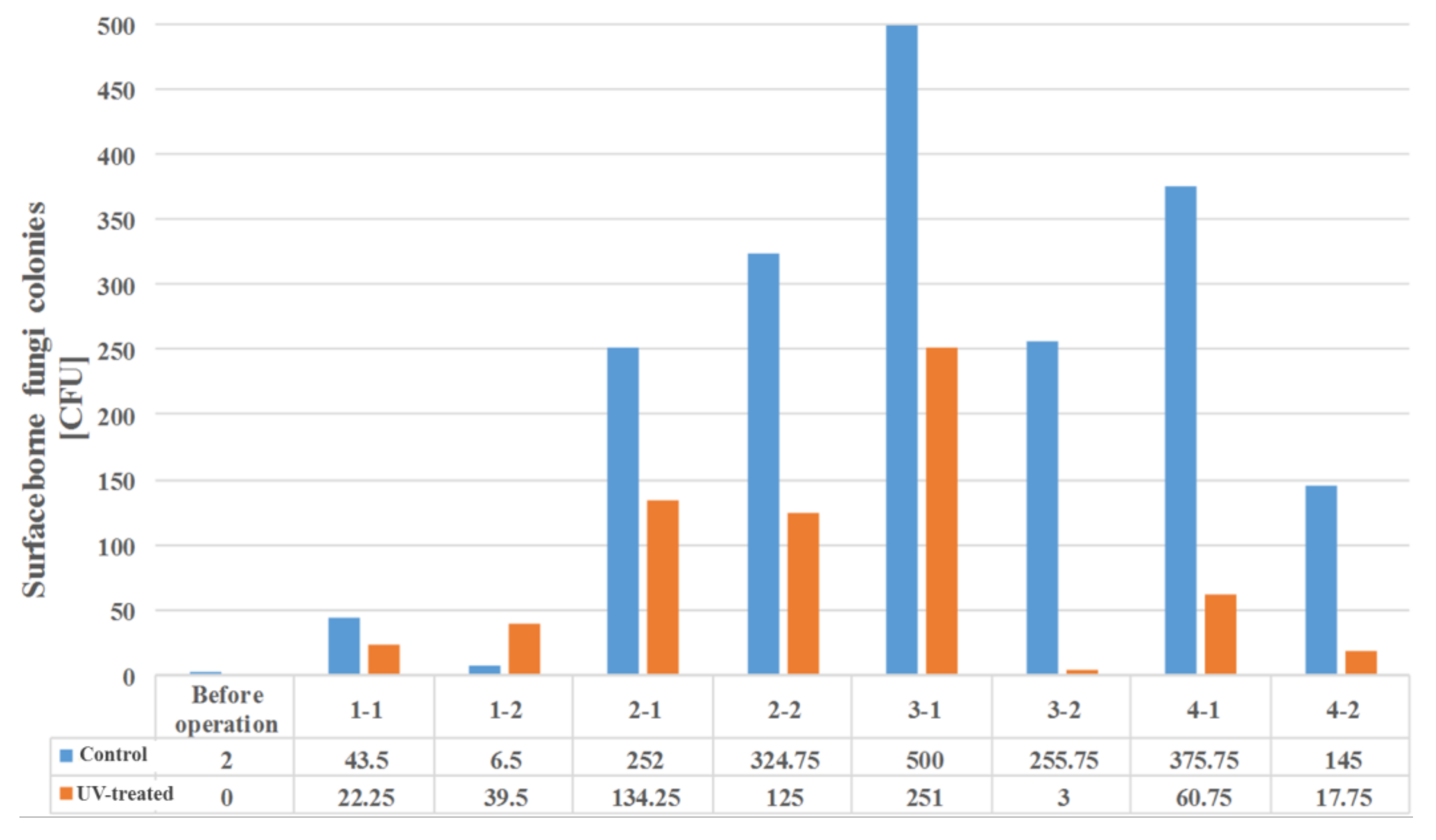
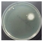
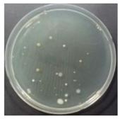
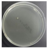
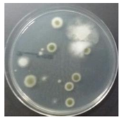
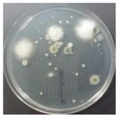
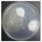
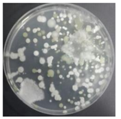
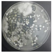
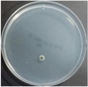
In both groups (Control and UV-treated), no correlation was found between the surface contamination of the sampled microorganisms and the duration of direct evaporative cooling. However, it was confirmed that the fungi were more sensitive to the ultraviolet ray reactor than the bacteria. In both cases, the contamination of bacterial and fungal surfaces was more severe in the outlet sides (outlet and upside outlet) of the four positions. It is predicted that the flow of process air will move the microorganisms in the evaporative cooling pad.
The pollution degree of outlet air of the direct evaporative cooling system increased in proportion to the operation time of the system, and both bacteria and fungi decreased more significantly in the UV-treated than in the Control samples. Through this, it was confirmed that the pollution degree of recirculated water influences the air quality in DEC.
Airborne microbes showed better air quality improvement in this study when compared to the results of Sung et al. [19]. Surface-borne microbes also showed a more pronounced improvement when compared to the results of Sung et al. [19].

5. Conclusions

The study empirically evaluated the improvement of microbial air qualityo on a direct evaporation cooling system. Experiments were performed for four weeks, and each divided into a control group (Control case corresponding to DEC that did not recycle water by bypassing the ultraviolet reactor) and experimental groups (UV-treated cases corresponding to DEC that involved recycled water treatment through an ultraviolet reactor). Water, surface, and air microorganisms were sampled twice a week a total of eight times.
In UV-treated cases, the bacterial concentration in the disinfected recirculating water increased after passing through the direct evaporative cooling pad. This indicates that circulating water is contaminated by surface bacteria contaminants in the evaporative cooling pad.
It was difficult to correlate the degree of bacterial and fungal contamination or type of microorganism on the surface of the direct evaporative cooling pad, given the duration of operation. However, the results confirmed that bacterial and fungal contamination were always higher on the outlet side when compared to that at the inlet side in all experimental periods.
A comparison of the air quality in Control and UV-treated cases indicated that airborne bacteria and fungi decreased when the water treatment was subjected to a UV reactor. The results confirmed that the air quality of the direct evaporative cooling system discharge air improved when the quality of recirculated water improved.
Therefore, the contamination of recirculated water in a direct cooling system affects air pollution. Water treatment techniques, such as ultraviolet water treatment systems, are also necessary for continuous water quality improvement in direct cooling systems.

Acknowledgments

This work was supported by the Korea Agency for Infrastructure Technology Advancement (KAIA) Grant (17CTAP-C116268-02), and the Korea Institute of Energy Technology Evaluation and Planning (KETEP) (No. 20164010200860).

Author Contributions

Wonjun Kim designed the research, conducted the experiment, and finished the writing of the paper; Hye-Won Dong contributed to conducting sampling and modified the manuscript; Junseok Park and Minki Sung gave comments on the experiment methods and results; Jae-Weon Jeong supervised the research design and execution and provided valuable suggestions during manuscript writing.

Conflicts of Interest

The authors declare no conflict of interest.

Appendix A

Table A1. Specifications of the UV reactor.
Reactor Model NumberMIN-3
Maximum water flow rate3 Gallons/min
Reactor diameter191 mm
Reactor length41.28 mm/10.8 mm
Lamp model numberAtlantic UV 05-1366
Lamp nominal length287 mm
Arc length225 mm
Quartz diameter15 mm
UV light wave length253.7 nm
Power consumption14 W
UV output3.7 W

References

  1. Goetzler, W.; Zogg, R.; Young, J.; Johnson, C. Energy Savings Potential and RD&D Opportunities for Non-Vapor-Compression HVAC Technologies; Navigant Consulting Inc., US Department of Energy: Washington, DC, USA, 2014.
  2. Kim, M.H.; Jeong, J.W. Cooling performance of a 100% outdoor air system integrated with indirect and direct evaporative coolers. Energy 2013, 52, 245–257. [Google Scholar] [CrossRef]
  3. Kim, M.H.; Park, J.Y.; Sung, M.K.; Choi, A.S.; Jeong, J.W. Annual operating energy savings of liquid desiccant and evaporative-cooling-assisted 100% outdoor air system. Energ. Build. 2014, 76, 538–550. [Google Scholar] [CrossRef]
  4. Heidarinejad, G.; Bozorgmehr, M.; Delfani, S.; Esmaeelian, J. Experimental investigation of two-stage indirect/direct evaporative cooling system in various climatic conditions. Build. Environ. 2009, 44, 2073–2079. [Google Scholar] [CrossRef]
  5. Duan, Z.; Zhan, C.; Zhang, X.; Mustafa, M.; Zhao, X.; Alimohammadisagvand, B.; Hasan, A. Indirect evaporative cooling: Past, present and future potentials. Renew. Sustain. Energ. Rev. 2012, 16, 6823–6850. [Google Scholar] [CrossRef]
  6. ASHRAE. Chapter 41. Evaporative air-cooing equipment. In ASHRAE Handbook—HVAC Systems and Equipment; American Society of Heating, Refrigerating and Air-Conditioning Engineers, Inc.: Atlanta, GA, USA, 2016. [Google Scholar]
  7. Bentham, R.H.; Broadbent, C.R. A model for autumn outbreaks of Legionnaires’ disease associated with cooling towers, linked to system operation and size. Epidemiol. Infect. 1993, 111, 287–295. [Google Scholar] [CrossRef] [PubMed]
  8. Ferré, M.S.; Arias, C.; Oliva, J.M.; Pedrol, A.; Garcia, M.; Pellicer, T.; Dominguez, A. A community outbreak of Legionnaires’ disease associated with a cooling tower in Vic and Gurb, Catalonia (Spain) in 2005. Eur. J. Clin. Microbiol. Infect. Dis. 2009, 28, 153. [Google Scholar] [CrossRef] [PubMed]
  9. Greig, J.E.; Carnie, J.A.; Tallis, G.F.; Ryan, N.J.; Tan, A.G.; Gordon, I.R.; Hart, W.G. An outbreak of Legionnaires’ disease at the Melbourne Aquarium, April 2000: investigation and case-control studies. Med. J. Aust. 2004, 180, 566. [Google Scholar] [PubMed]
  10. Hung, L.L.; Copperthite, D.C.; Yang, C.S.; Lewis, F.A.; Zampiello, F.A. Environmental Legionella assessment in office buildings of continental United States. Indoor Air 1993, 3, 349–353. [Google Scholar] [CrossRef]
  11. Bartram, J.; Chartier, Y.; Lee, J.V.; Pond, K.; Surman-Lee, S. Legionella and the Prevention of Legionellosis. Geneva, Switzerland: World Health Organization Press. 2007. Available online: http://www.who.int/water_sanitation_ health/emerging/legionella.pdf (accessed on 9 April 2018).
  12. ASHRAE. ANSI/ASHRAE Standard 12-2000, Minimizing the Risk of Legionellosis Associated with Building Water Systems; American Society of Heating, Refrigerating and Air-Conditioning Engineers, Inc.: Atlanta, GA, USA, 2000. [Google Scholar]
  13. Puckorius, P. Why evaporative coolers have not caused Legionnaires’ disease. Fuel Energy Abstr. 1995, 4, 300. [Google Scholar]
  14. Gómez, E.V.; Martínez, F.R.; González, A.T. The phenomenon of evaporative cooling from a humid surface as an alternative method for air-conditioning. Int. J. Energy Environ. 2010, 1, 69–96. [Google Scholar]
  15. Macher, J.M.; Girman, J.R. Multiplication of microorganisms in an evaporative air cooler and possible indoor air contamination. Environ. Int. 1990, 16, 203–211. [Google Scholar] [CrossRef]
  16. Strindehag, O.; Josefsson, I.; Henningson, E. Emission of bacteria from air humidifiers. Environ. Int. 1991, 17, 235–241. [Google Scholar] [CrossRef]
  17. Macher, J.M.; Girman, J.R.; Alevantis, L.A. Limited water-to-air bacterial transfer from a residential evaporative air cooler. Environ. Int. 1995, 21, 761–764. [Google Scholar] [CrossRef]
  18. Kang, Y.; Kato, S. A study on the effectiveness of microwave heating for disinfection of humidifier elements. HVAC&R Res. 2014, 20, 113–120. [Google Scholar] [CrossRef]
  19. Sung, M.; Kato, S.; Yanagi, U.; Kim, M.; Harada, M. Disinfection performance of ultraviolet germicidal irradiation systems for the microbial contamination on an evaporative humidifier. HVAC&R Res. 2011, 17, 22–30. [Google Scholar]
  20. Bolton, J.R.; Cotton, C.A. The Ultraviolet Disinfection Handbook; American Water Works Association: Denver, CO, USA, 2008. [Google Scholar]
  21. Yamamoto, H.; Urakami, I.; Nakano, K.; Ikedo, M.; Yabuuchi, E. Effects of FLONLIZER®, ultraviolet sterilizer, on Legionella species inhabiting cooling tower water. Microbiol. Immunol. 1987, 31, 745–752. [Google Scholar] [CrossRef] [PubMed]
  22. ASHRAE. ANSI/ASHRAE/IES Standard 133-2008 Method of Testing Direct Evaporative Air Coolers; American Society of Heating, Refrigerating and Air-Conditioning Engineers, Inc.: Atlanta, GA, USA, 2008. [Google Scholar]
  23. ASHRAE. ANSI/ASHRAE/IES Standard 90.1-2013 Energy Standard for Buildings Except Low-Rise Residential Buildings; American Society of Heating, Refrigerating and Air-Conditioning Engineers, Inc.: Atlanta, GA, USA, 2016. [Google Scholar]
  24. BUCK BioCulture. Bio-Contaminants Sampler Model B30120 Technical Brief; A.P. BUCK Inc.: Orlando, FL, USA, 2006. [Google Scholar]
  25. ISO16000-17. Indoor Air–Part 17: Detection and Enumeration of Moulds–Culture-Based Method; International Organization for Standardization (ISO): Geneva, Switzerland, 2011. [Google Scholar]
  26. ISO16000-18. Indoor Air–Part 18: Detection and Enumeration of Moulds–Sampling by Impaction; International Organization for Standardization (ISO): Geneva, Switzerland, 2011. [Google Scholar]
Figure 1. Schematic diagram of the direct evaporative cooling system.
Sustainability 10 01123 g001
Figure 2. Direct evaporative cooling system and UV reactor.
Sustainability 10 01123 g002
Figure 3. Sampling position in direct evaporative cooling system (DEC) (water, air, and surface).
Sustainability 10 01123 g003
Figure 4. Bacteria contamination of water from Control and UV-treated samples.
Sustainability 10 01123 g004
Figure 5. Bacterial contamination of the evaporative cooling pad surface in the Control and UV-treated samples.
Sustainability 10 01123 g005
Figure 6. Fungal contamination of the evaporative cooling pad surface in the Control and UV-treated samples.
Sustainability 10 01123 g006
Table 1. Bio-contamination sampling cases.
CaseOperation PeriodNumber of SamplingsNumber of Samples by Sample Type
Control (Not using UV reactor)4 Weeks2 Times/WeekWater: 1 point
Surface: 4 points
Air: 2 points
UV-treated (Using UV reactor)4 Weeks2 Times/WeekWater: 2 points
Surface: 4 points
Air: 2 points
Table 2. Specification of the bio-contaminants air sampler [24].
DeviceTypeCharacteristics
Bio-contaminants samplerImpactor typeDetection flow30 to 120 L/min
Compatibility90 mm agar plate
Detecting accuracy±5% of set point
Holes380 (1 mm diameter)
Table 3. Sampling and incubation details of microbial contamination.
Sample TypeSample MaterialSampling MethodAgar and Petri FilmIncubate TemperatureIncubate Times
BacteriaWaterSterile sample bottleAC Film32 °C3 Days (72 h)
SurfaceSwab methodAC Film
AirImpactor air samplerTSA
FungusSurfaceSwab methodYM Film25 °C5 Days (120 h)
AirImpactor air samplerPDA
* AC Film: Aerobic count plate, indicator that facilitates colony enumeration. * YM Film: Yeast and mold culture film. * TSA: Trypticase soy agar. * PDA: Potato dextrose agar.
Table 4. Operating details and conditions of the DEC.
Air Handling SystemDirect Evaporative Cooling System
Operating time9:00 a.m.–6:00 p.m.
Supply air flow rate300–370 m3/h
Face velocity0.75–0.88 m/s
Inlet air temperature28–32 °C
Outlet air temperature19–22 °C
DEC cooling effectiveness ( ε D E C )95–98%
Sump water temperature21–26 °C
Water flow rate5–6 L/min
Table 5. Number of bacteria colonies in the Control case.
WeekMeasuring DateInletOutlet
1 min2 min1 min2 min
17.10 Sustainability 10 01123 i001 Sustainability 10 01123 i002 Sustainability 10 01123 i003 Sustainability 10 01123 i004
Number of colonies0, 07, 619, 2944, 26
CFU/m322197
27.17 Sustainability 10 01123 i005 Sustainability 10 01123 i006 Sustainability 10 01123 i007 Sustainability 10 01123 i008
Number of colonies1, 02, 1465, 357TNTC, TNTC
CFU/m374110
37.27 Sustainability 10 01123 i009 Sustainability 10 01123 i010 Sustainability 10 01123 i011 Sustainability 10 01123 i012
Number of colonies1, 34, 8TNTC, TNTCTNTC, TNTC
CFU/m327TNTC
48.2 Sustainability 10 01123 i013 Sustainability 10 01123 i014 Sustainability 10 01123 i015 Sustainability 10 01123 i016
Number of colonies0, 22, 3TNTCTNTC
CFU/m312TNTC
Table 6. Number of bacteria colonies in the UV-treated case.
WeekMeasuring DateInletOutlet
1 min2 min1 min2 min
18.14 Sustainability 10 01123 i017 Sustainability 10 01123 i018 Sustainability 10 01123 i019 Sustainability 10 01123 i020
Number of colonies3, 41, 041, 4084, 66
CFU/m313385
28.21 Sustainability 10 01123 i021 Sustainability 10 01123 i022 Sustainability 10 01123 i023 Sustainability 10 01123 i024
Number of colonies0, 21, 089, 64122, 88
CFU/m35605
39.1 Sustainability 10 01123 i025 Sustainability 10 01123 i026 Sustainability 10 01123 i027 Sustainability 10 01123 i028
Number of colonies1, 23, 17180, 119317, 306
CFU/m3371537
49.8 Sustainability 10 01123 i029 Sustainability 10 01123 i030 Sustainability 10 01123 i031 Sustainability 10 01123 i032
Number of colonies0, 03, 2157, 151285, 237
CFU/m381383
Table 7. Number of fungi colonies in the Control case.
WeekMeasuring DateInletOutlet
2 min5 min2 min5min
17.10 Sustainability 10 01123 i033 Sustainability 10 01123 i034 Sustainability 10 01123 i035 Sustainability 10 01123 i036
Number of colonies9, 511, 924, 3146, TNTC
CFU/m328112
27.17 Sustainability 10 01123 i037 Sustainability 10 01123 i038 Sustainability 10 01123 i039 Sustainability 10 01123 i040
Number of colonies2, 112, 1885, 72145, 61
CFU/m324259
37.27 Sustainability 10 01123 i041 Sustainability 10 01123 i042 Sustainability 10 01123 i043 Sustainability 10 01123 i044
Number of colonies0, 02, 0UncountableUncountable
CFU/m33Uncountable
48.2 Sustainability 10 01123 i045 Sustainability 10 01123 i046 Sustainability 10 01123 i047 Sustainability 10 01123 i048
Number of colonies0, 00, 4UncountableUncountable
CFU/m37Uncountable
Table 8. Number of fungi colonies in UV-treated cases.
WeekMeasuring DateInletOutlet
1 min2 min1 min2 min
18.14 Sustainability 10 01123 i049 Sustainability 10 01123 i050 Sustainability 10 01123 i051 Sustainability 10 01123 i052
Number of colonies1, 10, 085, 3270, 65
CFU/m33420
28.21 Sustainability 10 01123 i053 Sustainability 10 01123 i054 Sustainability 10 01123 i055 Sustainability 10 01123 i056
Number of colonies6, 311, 658, 60146, 198
CFU/m343770
39.1 Sustainability 10 01123 i057 Sustainability 10 01123 i058 Sustainability 10 01123 i059 Sustainability 10 01123 i060
Number of colonies1, 21, 219, 170124, TNTC
CFU/m310783
49.8 Sustainability 10 01123 i061 Sustainability 10 01123 i062 Sustainability 10 01123 i063 Sustainability 10 01123 i064
Number of colonies2, 23, 141, 4551, 60
CFU/m313328

