1. Introduction
Recent projections predict that the primary energy consumption will rise by 48% in 2040 [
1]. On the other hand, the depletion of fossil resources in addition to their negative impact on the environment has accelerated the shift toward sustainable energy sources. Renewable energies such as solar radiation, ocean waves, wind, and biogas have been playing a major role in reforming the natural balance and providing the needs of the growing population demand [
2]. However, due to the climatic vagaries, the means of storing these types of renewable energy has become urgent [
3]. This has lead to a need to develop efficient and sustainable methods of storing energy.
Energy storage has become an important part of renewable energy technology systems. Thermal energy storage (TES) is a technology that stocks thermal energy by heating or cooling a storage medium so that the stored energy can be used at a later time for heating and cooling applications [
4] and power generation. TES systems are used particularly in buildings and in industrial processes. Advantages of using TES in an energy system include an increase in overall efficiency and better reliability, and it can lead to better economics, reductions in investment and running costs, and less pollution of the environment, i.e., fewer carbon dioxide (CO
2) emissions [
5]. Solar thermal systems, unlike photovoltaic systems with striving efficiencies, are industrially mature and utilize a major part of the Sun’s thermal energy during the day. Yet, it does not have enough (thermal) backup to continue operating during the low or no solar radiation hours. TES is becoming particularly important for electricity storage in combination with concentrating solar power (CSP) plants where solar heat can be stored for electricity production when sunlight is not available. New materials are selected, characterized, and enhanced in their thermo-physical properties to serve the purpose of a 24 h operation in an efficient TES system.
In Europe, it has been estimated that around 1.4 million GWh/year can be saved and 400 million tons of CO
2 emissions avoided, in buildings and in industrial sectors by more extensive use of heat and cold storage [
6].
Storage density, in terms of the amount of energy per unit of volume or mass, is important for optimizing solar ratio (how much solar radiation is useful for the heating/cooling purposes), efficiency of appliances (solar thermal collectors and absorption chillers), and energy consumption for space heating/coolingroom consumption. Therefore, the possibility of using phase-change materials (PCMs) in solar system applications is worth investigating. PCMs might be able to increase the energy density of small-sized water storage tanks, reducing solar storage volume for a given solar fraction or increasing the solar fraction for a given available volume [
7].
It is possible to consider thermal storage on the hot and/or cold side of the plant. The former allows the storage of hot water from the collectors (and from the auxiliary heater) to be supplied to the generator of the absorption chiller (in cooling mode) or directly to the users (in heating mode). The latter allows the storage of cold water produced by the absorption chiller to be supplied to the cooling terminals inside the building. It is usual to identify three situations as “hot”, “warm”, and “cold” storage based on the different temperature ranges. Typically, a hot tank may work at 80–90 °C, a warm tank at 40–50 °C, and a cold tank at 7–15 °C [
8].
While heat storage on the hot side of solar plants are always present because of heating and/or domestic hot water (DHW) production, cold storage is justified in larger plants. Cold storages are used not only to gain economic advantages from lower electricity costs (in the case of electric compression chillers) depending on the time of day but also to lower the cooling power installed and to allow more continuous operation of the chiller [
9].
The use of thermal storage, initially, could not provide effective backup but helped the system to thermally stabilize. Consequently, thermal storage found use in solar-assisted thermal systems [
10]. Since then, studying thermal energy storage technologies as well as the usability and effects of both sensible and latent heat storage in numerous applications increased, leading to a number of reviews [
11,
12,
13,
14,
15]. These reviews focused only on one side (cold or hot) or component of the system or one of its integral mechanism.
For example, Pintaldi et al. [
16] reviewed thermal energy storage technologies and control approaches for solar cooling system. They mainly focused on types of thermal storages used in solar cooling applications, with emphasis on higher temperatures (>100 °C). Tian and Zhao [
17] compiled various types of research in solar collectors and thermal energy storages used for solar thermal applications. Joybari et al. [
18] compiled a review on PCM for cold storage for the application of domestic refrigeration, i.e., evaporator side only. The study performed by Orό et al. [
19] also covered ice storage and air conditioning separately.
This paper is focused on the analysis of TES technologies that provides a way of valorizing solar heat and reducing the energy demand of buildings. The principles of several energy storage methods and calculation of storage capacities are described. Sensible heat storage (SHS) technologies, including the use of water, underground, and packed-bed storage methods, are briefly reviewed. Latent-heat storage (LHS) systems associated with PCMs for use in the solar heating and cooling of buildings, solar water heating, heat-pump systems, and CSP plants as well as thermo-chemical storage (TCS) are also discussed. Finally, cool thermal energy storage is also briefly reviewed and outstanding information on the performance and costs of TES systems are included.
2. Classification and Characteristics of Storage Systems
Due to intermittency in availability and constant variation in solar radiation, TES found its place in thermodynamic systems. TES not only reduces the discrepancy between the demand and supply by conserving energy, but also improves the performance and thermal reliability of the system. Therefore, designing efficient and economical TES systems is of high importance. However, few solar thermal plants in the world have employed TES at a large scale. Additionally, the design of TES systems in various domestic solar applications is currently being investigated [
20]. Using a computational fluid dynamic approach is also a vastly used method to save money, where FLUENT software seems to be successfully used for different engineering applications [
21].
The main types of thermal energy storage of solar energy are presented in
Figure 1. An energy storage system can be described in terms of the following characteristics [
6]:
Capacity defines the energy stored in the system and depends on the storage process, the medium, and the size of the system;
Power defines how fast the energy stored in the system can be discharged (and charged);
Efficiency is the ratio of the energy provided to the user to the energy needed to charge the storage system. It accounts for the energy loss during the storage period and the charging/discharging cycle;
Storage period defines how long the energy is stored and lasts hours to months (i.e., hours, days, weeks, and months for seasonal storage);
Charge and discharge time defines how much time is needed to charge/discharge the system; and
Cost refers to either capacity (€/kWh) or power (€/kW) of the storage system and depends on the capital and operation costs of the storage equipment and its lifetime (i.e., the number of cycles).
Capacity, power, and discharge time are interdependent variables. In some storage systems, capacity and power can also depend on each other. Typical parameters for TES systems are shown in
Table 1 [
22], including capacity, power, efficiency, storage period, and cost. High-energy storage density and high power capacity for charging and discharging are desirable properties of any storage system. It is well known that there are three methods for TES at temperatures from −40 °C to more than 400 °C: sensible heat, latent heat associated with PCMs, and thermo-chemical heat storage associated with chemical reactions (
Figure 2) [
23].
The choice of storage medium depends on the nature of the process. For water heating, energy storage as sensible heat of stored water is logical. If air-heating collectors are used, storage in sensible or latent heat effects in particulate storage units is indicated, such as sensible heat in a pebble-bed heat exchanger. In passive heating, storage is provided as sensible heat in building the elements. If photovoltaic or photo-chemical processes are used, thermo-chemical storage is logical.
3. Sensible Heat Storage
SHS (
Figure 2a) is the simplest method based on storing thermal energy by heating or cooling a liquid or solid storage medium (e.g., water, sand, molten salts, or rocks), with water being the cheapest option. The most popular and commercial heat storage medium is water, which has a number of residential and industrial applications. Underground storage of sensible heat in both liquid and solid media is also used for typically large-scale applications. SHS has two main advantages: it is cheap and without the risks associated with the use of toxic materials.
SHS system utilizes the heat capacity and the change in temperature of the storage medium during the process of charging and discharging. The amount of heat stored depends on the specific heat of the medium, the temperature change, and the amount of storage material [
24].
where
Qs is the quantity of heat stored, in Joules;
m is the mass of heat storage medium, in kg;
cp is the specific heat, in J/(kg·K);
ti is the initial temperature, in °C;
tf is the final temperature, in °C.
Table 2 shows the most used SHS materials and their properties [
25]. Water appears to be the best SHS liquid available because it is inexpensive and has a high specific heat. However, above 100 °C, oils, molten salts, and liquid metals are used. For air heating applications, rock bed type storage materials are used.
Table 3 shows the main characteristics of the most commonly used solid-state thermal storage materials [
17], including sand-rock minerals, concrete, fire bricks, and ferroalloy materials. These materials have working temperatures from 200 to 1200 °C and have excellent thermal conductivities: 1.0 W/(m·K)–7.0 W/(m·K) for sand-rock minerals, concrete, and fire bricks; 37.0 W/(m·K)–40.0 W/(m·K) for ferroalloy materials. The materials shown in
Table 3 are all low-cost, ranging from 0.05 to 5.00
$/kg. The only disadvantage is their heat capacities being rather low, ranging from 0.56 to 1.3 kJ/(kg⋅°C), which can make the storage unit unrealistically large.
3.1. Water Tank Storage
The most common material used in a sensible heat storage system is water. The use of hot-water tanks is a well-known technology for thermal energy storage [
26]. Hot-water tanks serve the purpose of energy saving in water heating systems via solar energy and via co-generation (i.e., heat and power) energy supply systems. State-of the-art projects [
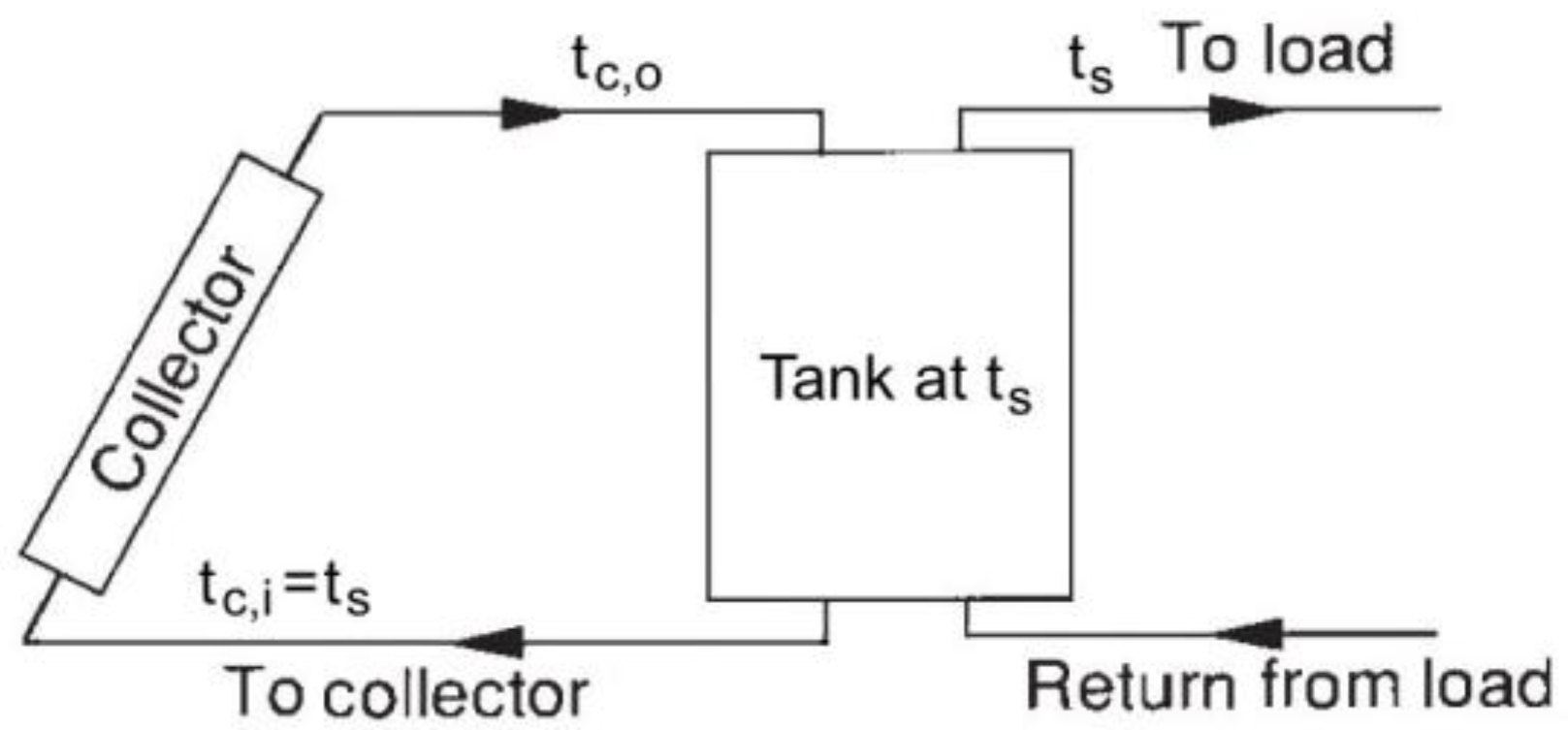
27] have shown that water tank storage is a cost-effective storage option and that its efficiency can be further improved by ensuring optimal water stratification in the tank and highly effective thermal insulation. Today’s research and development (R&D) activities focus, for example, on evacuated super-insulation with a thermal conductivity of 0.01 W/(m·K) at 90 °C and 0.1 mbar and on an optimized system integration. A typical system in which a water tank is used is shown in
Figure 3.
The energy storage capacity of a water (or other liquid) storage unit at uniform temperature (i.e., fully mixed or no stratified) operating over a finite temperature difference is given by Equation (1) redefined as
where
Qs is the total heat capacity for a cycle operating through the temperature range ∆
ts, and
m and
cp are the mass and the specific heat, respectively, of water in the unit. The temperature range over which such a unit can operate is limited at the lower extreme for most applications by the requirements of the process. The upper limit may be determined by the process, the vapor pressure of the liquid, or the collector heat loss.
An energy balance on the no stratified tank is
where
Qu and
QL are rates of addition or removal of energy from the collector and to the load;
Us is the heat loss coefficient of storage tank;
As is the storage tank surface area;
tf is the final temperature, in °C;
ta is the ambient temperature for the tank;
τ is the time.
Equation (3) is to be integrated over time to determine the long-term performance of the storage unit and the solar process. Useful long-term analytical solutions are not possible due to the complex time dependence of some of the terms. There are many possible numerical integration methods. Using simple Euler integration is usually satisfactory (i.e., rewriting the temperature derivative as (
ts −
ti)/∆
τ and solving for the tank temperature at the end of a time increment):
Equation (4) can be used to predict water storage temperature as a function of time. Once the tank temperature is known, other temperature-dependent quantities can be estimated.
Hot water storage systems used as buffer storage for DHW supply are usually in the range of 500 L to several cubic meters (m
3). This technology is also used in solar thermal installations for DHW combined with building heating systems (comb-systems). Large hot-water tanks are used for seasonal storage of solar thermal heat in combination with small district heating systems. These systems can have a volume up to several thousand cubic meters. Charging temperatures are in the range of 80–90 °C. The usable temperature difference can be enhanced by the use of heat pumps for discharging (down to temperatures around 10 °C) [
4].
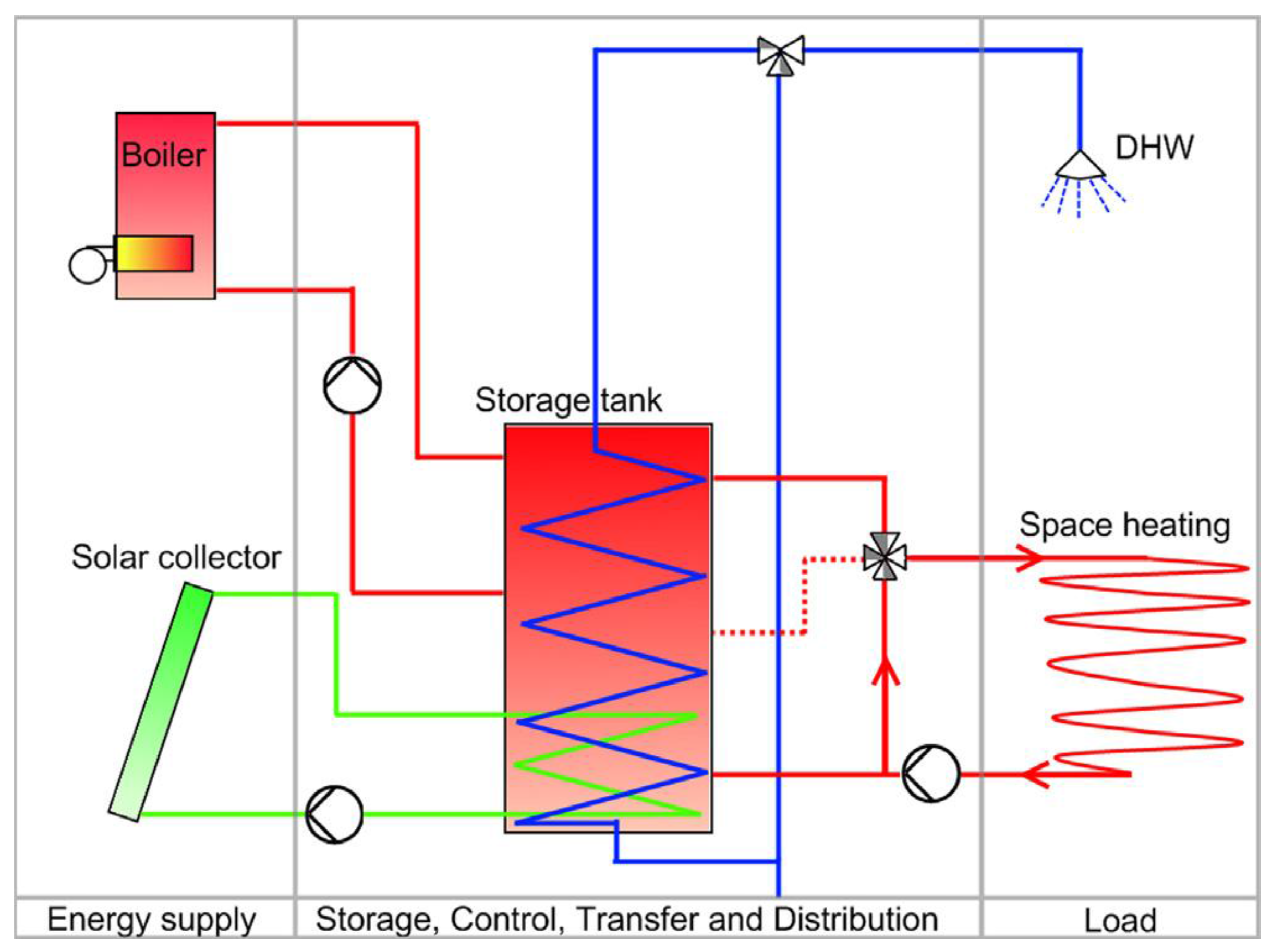
A more complex system with tank storage is shown in
Figure 4; a solar combisystem where water store is the central part. The so-called combistore is charged with solar collectors and a second heating source, such as a biofuel or gas boiler, and heat is extracted to two heat sinks of very different characteristics: domestic hot water and space heating [
28]. Solar combisystems including combistores were also the topic of the European project Combisol, whose goal was the promotion and standardization of solar combisystems in Europe [
29].
High specific heat capacity, wide availability, chemically stability, and low cost make water a good storage media suitable for low temperature solar cooling applications (e.g., single stage absorption chillers and desiccant systems). Due to the boiling point constraint (100 °C at 1 bar), the use of water as sensible heat storage medium for high temperature application (double effect and triple effect chillers) requires increasing the system pressure [
16].
3.2. Underground Storage
Underground thermal energy storage (UTES) is also a widely used storage technology, which makes use of the ground (e.g., the soil, sand, rocks, and clay) as a storage medium for both heat and cold storage.
Means must be provided to add energy to and remove it from the medium. This is done by pumping heat transfer fluids (HTFs) through pipe arrays in the ground. The pipes may be vertical U-tubes inserted in wells (boreholes) that are spaced at appropriate intervals in the storage field or they may be horizontal pipes buried in trenches. The rates of charging and discharging are limited by the area of the pipe arrays and the rates of heat transfer through the ground surrounding the pipes. If the storage medium is porous, energy transport may occur by evaporation and condensation and by the movement of water through the medium, and a complete analysis of such a store must include consideration of both heat and mass transfer. These storage systems are usually not insulated, although insulation may be provided at the ground surface.
Boreholes (ground heat exchangers) are also frequently used in combination with heat pumps where the ground heat exchanger extracts low-temperature heat from the soil.
Aquifer storage is closely related to ground storage, except that the primary storage medium is water, which flows at low rates through the ground. Water is pumped out of and into the ground to heat it and extract energy from it. Water flow also provides a mechanism for heat exchange with the ground itself. As a practical matter, aquifers cannot be insulated. Only aquifers that have low natural flow rates through the storage field can be used. A further limitation may be in chemical reactions of heated water with the ground materials. Aquifers, as with ground storage, operate over smaller temperature ranges than water stores. Most applications deal with the storage of winter cold to be used for the cooling of large office buildings and industrial processes in the summer.
Aquifer storage is discussed by Novo et al. [
30], who mention that the heat capacity for aquifers is in the range of 30–40 kWh/m
3 and the storage volume for 1 m
3 water equivalents is 2–3 m
3. It is emphasized that the relative heat losses get smaller for larger storage volumes, since the area susceptible to heat loss per volume decreases. A state-of-the-art review for aquifer storage for heating and cooling of buildings is presented by Paksoy et al. [
31], who explained that, because of the ground conditions needed for aquifer storage, it is much less applicable than borehole storage, though aquifer storage has many advantages over borehole storage. The main advantage mentioned is the fact that it is possible to achieve much higher power rates from an aquifer since water can be pumped at a high rate.
Cavern storage and pit storage are based on large underground water reservoirs created in the subsoil to serve as TES systems. Caverns are the same in their principles of operation as the tanks discussed in the previous section. Energy is added to or removed from the store by pumping water into or out of the storage unit. The major difference will be in the mechanisms for heat loss and the possible thermal coupling with the ground. These storage options are technically feasible, but applications are limited because of the high investment costs. A German central solar heating plant with seasonal storage is described by Bauer et al. [
32], who also discuss the heat losses from certain installations. For example, for seasonal water storage with a volume of 12,000 m
3 in Friedrichshafen, the yearly heat losses from the store were between 322 and 482 MWh, yielding a storage utilization factor of around 60%. The solar fraction for this system was lower than expected (between 21 and 33% instead of a projected 43%), and the reasons given are a higher heat demand from the buildings and higher return temperatures to the store. For a seasonal borehole storage evaluated by Heier et al. [
33], the borehole storage itself is shown to have a yearly heat loss of approximately 50% of the solar energy that is charged into the store.
For high-temperature (i.e., above 100 °C) SHS, the technology of choice is based on the use of liquids (e.g., oil or molten salts, the latter for temperatures up to 550 °C). For very high temperatures, solid materials (e.g., ceramics and concrete) are also taken into consideration. However, most of such high-temperature-sensible TES options are still under development or demonstration.
3.3. Packed-Bed Storage
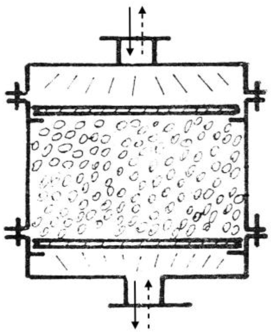
A packed-bed (pebble-bed) storage unit uses the heat capacity of a bed of loosely packed particulate material to store energy. A fluid, usually air, is circulated through the bed to add or remove energy. A variety of solids may be used, rock and pebble being the most widely used materials.
A pebble-bed storage unit is shown in
Figure 5. In operation, flow is maintained through the bed in one direction during addition of heat (usually downward) and in the opposite direction during removal of heat. Note that heat cannot be added and removed at the same time; this is in contrast to water storage systems, where simultaneous addition to and removal from storage is possible.
A major advantage of a packed-bed storage unit is its high degree of stratification. The pebbles near the entrance are heated, but the temperature of the pebbles near the exit remains unchanged and the exit-air temperature remains very close to the initial bed temperature. As time progresses a temperature front passes through the bed. When the bed is fully charged, its temperature is uniform.
A packed bed in a solar heating system does not normally operate with constant inlet temperature. During the day, the variable solar radiation, the ambient temperature, the collector inlet temperature, load requirements, and other time-dependent conditions result in a variable collector outlet temperature.
Many studies on the heating and cooling of packed beds have been published. The first analytical study was by Schumann [
34], and the basic assumptions leading to this model are a one-dimensional plug flow, no axial conduction or dispersion, constant properties, no mass transfer, no heat loss to the environment, and no temperature gradients within the solid particles. The differential equations for the fluid and bed temperatures (
tf,
tb) are as follows:
where ρ
f is the fluid density;
cp,f is the specific heat of fluid; ε is the bed void fraction;
mf is the fluid mass;
A is the bed cross-sectional area;
kv is the volumetric (per unit bed volume) heat transfer coefficient between the bed and the fluid;
τ is the time.
For an air-based system, the first term on the left-hand side of Equation (5) can be neglected and the equations can be written as follows [
35]:
and the dimensionless time is
where
A is the bed cross-sectional area;
L is the bed length;
NTU is the effectiveness.
Analytical solutions to these equations exist for a step change in inlet conditions and for cyclic operation. For the long-term study of solar energy systems, these analytical solutions are not useful, and numerical techniques such as the finite-difference method must be employed.
Nems et al. [
36] present the results of a study into a packed-bed filled with ceramic bricks. The designed storage installation is supposed to become part of a heating system installed in a single-family house and eventually to be integrated with a concentrated solar collector adapted to climate conditions in Poland. The system’s working medium is air. The investigated temperature ranges and air volume flow rates in the ceramic bed were dictated by the planned integration with a solar air heater. The analysis of the obtained characteristics allowed for the conclusion that the process of heat storage in ceramic brick has high efficiency, which, during the experiment, was in the range of 72–93% for an airflow rate of 0.0050 m
3/s and 74–96% for an airflow rate of 0.0068 m
3/s. The choice of ceramic bricks as the filling material was dictated by several reasons. Structural stability can be provided more easily to a large bed filled with bricks than to a bed filled with, e.g., crushed stone or pebbles. Brick is also an easily available material and has good thermal properties. Additionally, brick is resistant to high temperatures and tolerates a high number of charge/discharge cycles. Brick does not emit any harmful gases in high temperatures, which is important, as the storage unit is to be located inside a residential house.
As demonstrated in [
36], a system in which heat is stored in a sensible heat storage material, such as ceramic brick, should be provided with a means to control airflow rate in order to maximize the effectiveness of heat storage process, if the heat comes from a source of variable intensity, such as a concentrated solar air collector.
4. Latent-Heat or Phase-Change Storage
LHS materials are known as PCMs due to their property of releasing or absorbing energy with a change in physical state. The energy storage density increases and hence the volume is reduced, in the case of LHS (
Figure 2b). The heat is mainly stored in the phase-change process (at a quite constant temperature) and it is directly connected to the latent heat of the substance. The use of an LHS system using PCMs is an effective way of storing thermal energy and has the advantages of high-energy storage density and the isothermal nature of the storage process.
The main advantage of using LHS over SHS is their capacity of storing heat at almost similar temperature range. Initially, these materials act like SHS materials in that the temperature rises linearly with the system enthalpy; however, later, heat is absorbed or release at almost constant temperature with a change in physical state.
LHS is based on the heat absorption or release when a storage material undergoes a phase change from solid to liquid or liquid to gas or vice versa. The storage capacity
Qs, in J, of the LHS system with a PCM medium [
17] is given by
where
tm is the melting temperature, in °C;
m is the mass of PCM medium, in kg;
cps is the average specific heat of the solid phase between
ti and
tm, in kJ/(kg⋅K);
cpl is the average specific heat of the liquid phase between
tm and
tf, in J/(kg⋅K);
f is the melt fraction; Δ
q is the latent heat of fusion, in J/kg. For example, Glauber’s salt
(Na
2SO
4⋅10H
2O
) has c
ps ≈ 1950 J/(kg⋅°C), c
pl ≈ 3550 J/(kg⋅°C), and Δ
q = 2.43 × 10
5 J
/kg at 34 °C.
The measurement techniques presently used for latent heat of fusion and melting temperature of PCMs are (1) differential thermal analysis (DTA) and (2) differential scanning calorimeter (DSC) [
17]. In DSC and DTA techniques, sample and reference materials are heated at a constant rate. The temperature difference between them is proportional to the difference in heat flow between the two materials and the record is the DSC curve. The recommended reference material is alumina (Al
2O
3). Latent heat of fusion is calculated using the area under the peak, and the melting temperature is estimated by the tangent at the point of greatest slope on the face portion of the peak.
Morrison and Abdel-Khalik [
37] developed a model applicable to PCMs in small containers, where the length in the flow direction is
L, the cross-sectional area of the material is
A, and the wetted perimeter is
P. The heat transfer fluid passes through the storage unit in the
x direction at the mass flow rate
m and with inlet temperature
tf,i.
The model is based on three assumptions: (1) during flow, axial conduction in the fluid is negligible; (2) the Biot number is low enough that temperature gradients normal to the flow can be neglected; and (3) heat losses from the bed are negligible.
An energy balance on the material gives
where
u, ts, λs, and ρ
s are the specific internal energy, temperature, thermal conductivity, and density of the PCM;
tf and
U are the circulating fluid temperature and overall heat transfer coefficient between the fluid and PCM;
τ is the time.
An energy balance on the fluid is
where ρ
f, Af, and
cp,f are the density, flow area, and specific heat of the fluid.
The equation and boundary conditions for PCM storage can be simplified for particular cases. It has been shown that axial conduction during flow is negligible, and if the fluid capacitance is small, Equations (13) and (14) become [
35]
where ratio Θ =
τmcp,f/ρ
sAL and effectiveness
NTU =
UPL/(
mcp,f).
As depicted in
Figure 1, the phase change process takes place in different modes: solid–solid, liquid–gas, and solid–liquid. In the first case, heat is stored by transition between different kinds of crystallization forms. For liquid–gas systems, latent heat is very high, but there are problems in storage control due to the high volume variations during phase change. The most widespread are the solid–liquid PCMs, which have a limited volume variation during latent heat exchange (generally less than 10%) and a fairly high melting latent heat. Melting processes involve energy densities of 100 kWh/m
3 (e.g., ice) compared to a typical 25 kWh/m
3 for SHS options. PCMs can be used for both short-term (daily) and long-term (seasonal) energy storage, using a variety of techniques and materials. Possible applications of PCMs are as follows:
- −
implementation in gypsum board, plaster, concrete, or other wall covering material being part of the building structure to enhance the thermal energy storage capacity, with main utilization in peak-load shifting (and shaving) and solar energy [
38] (in this application, typical operating temperature is 22–25 °C, but it can vary as a function of climate and heating/cooling loads);
- −
cold storage for cooling plants (operating temperature 7–15 °C) [
26];
- −
warm storage for heating plants (40–50 °C) [
26];
- −
hot storage for solar cooling and heating (80–90 °C) [
26].
Any latent heat energy storage system therefore possesses at least following three components:
a suitable PCM with its melting point in the desired temperature range,
a suitable heat exchange surface, and
a suitable container compatible with the PCM.
4.1. Characteristics Proprieties of PCMs
PCMs have been used in thermal applications for a few decades. PCMs have
- −
thermo-physical properties (latent heat of transition and thermal conductivity should be high, and density and volume variations during phase-transition should be, respectively, high and low in order to minimize storage volume),
- −
kinetic and chemical properties (super-cooling should be limited to a few degrees, and materials should have long-term chemical stability, compatibility with materials of construction, no toxicity, and no fire hazard), and
- −
economic advantages (low cost and large-scale availability of the PCMs are also very important).
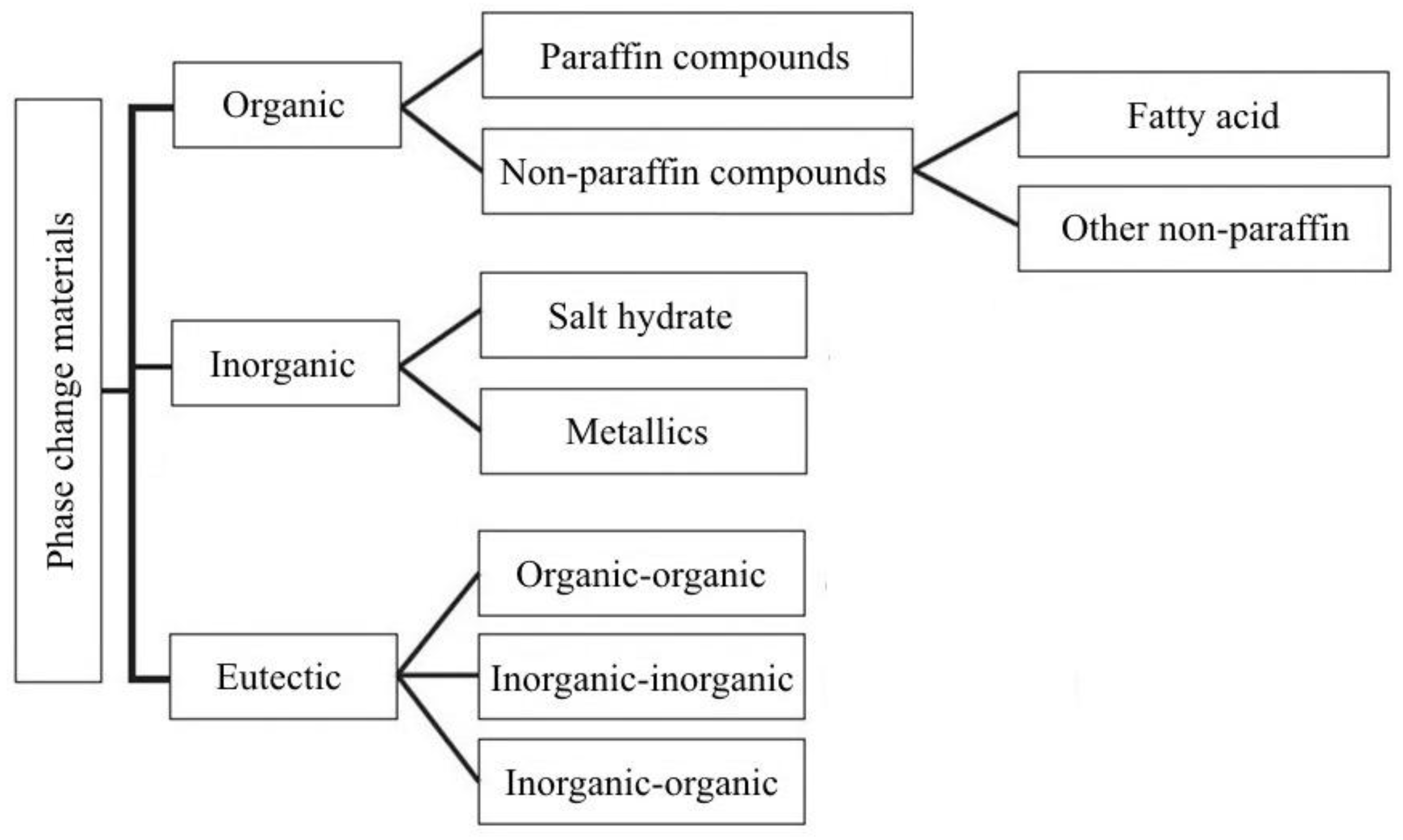
LHS materials are broadly classified based on their physical transformation for heat absorbing and desorbing capabilities. As seen from
Figure 6, wide classifications of solid–liquid PCMs, which are further classified into organic, inorganic, and eutectic materials, are presented. PCMs are classified as different groups depending on the material nature (paraffin, fatty acids, salt hydrates, etc.). A few advantages and disadvantages of organic and inorganic PCMs and their influence on solar cooling application are listed in
Table 4 [
39].
Considering real applications in thermal energy store, the most widespread materials are paraffin’s (organics), hydrated salts (inorganic), and fatty acids (organics). In cold storage, ice water is often used as well.
Table 5 shows some of the most relevant PCMs in different temperature ranges with their melting temperature, enthalpy, and density.
An original composite PCM of caprylic-nonanoic acid/expanded graphite (CA-NA/EG) with an optimum absorption ratio (CA-NA/EG = 90:10, by mass) was prepared by Wang et al. [
40]. The composite PCM has no supercooling, proper melting point, acceptable latent heat and thermal conductivity, and excellent thermal reliability and stability.
4.1.1. Organic PCMs
Organic PCMs can melt and solidify many times without phase segregation, and because of the degradation of their latent melting heat, they crystallize with little or no super-cooling and are usually non-corrosive. The two main groups are:
- (1)
Paraffin waxes consist of a mixture of mostly straight chain
n-alkenes CH
3–(CH
2)–CH
3. The crystallization of the (CH
3)– chain release a large amount of latent heat. Both the melting point and latent heat of fusion increase with chain length. Due to cost consideration, however, only technical grade paraffin’s may be used as PCMs in latent heat storage systems. Paraffin is safe, reliable, predictable, less expensive, non-corrosive, and available in a large temperature range (5–80 °C) [
11].
- (2)
Non-paraffin organic PCMs are the most numerous of the PCMs with highly varied properties. A number of esters, fatty acids, alcohols, and glycols suitable for energy storage have been identified [
41]. Main features of these organic materials include high heat of fusion, inflammability, low thermal conductivity, low flash points, and instability at high temperatures.
Details of thermal properties, applications, and limitations of fatty acids are discussed in [
42] and those of sugar alcohols/polyols are found in [
43,
44].
4.1.2. Inorganic PCMs
Inorganic PCMs are (mostly) used in high-temperature solar applications and one of the most reported challenges is their maintenance. At lower temperatures, they freeze; at high temperatures, they are difficult to handle. These PCMs do not super-cool appreciably and their melting enthalpies do not degrade with cycling. The two main types are as follows:
(1)
Salt hydrate. This is classified as a congruent, incongruent, and semi-congruent melting method [
11]. They are alloys of inorganic salts (AB) and
n kmol of water, forming a typical crystalline solid of general formula AB⋅
nH
2O, whose solid–liquid transition is actually a dehydration and hydration of the salt. A salt hydrate usually melts either to a salt hydrate with fewer moles of water, i.e.,
or to its anhydrous form,
At the melting point, the hydrate crystals break-up into anhydrous salt and water, or into a lower hydrate and water. One problem with most salt hydrates is that of incongruent melting caused by the fact that the released water of crystallization is not sufficient to dissolve all the solid phase present. Due to density difference, the lower hydrate (or anhydrous salt) settles down at the bottom of the container.
Salt hydrates have been extensively studied in heat storage applications because of their positive characteristics: high latent heat of fusion per unit volume, a relatively high thermal conductivity (almost double that of paraffin), low corrosiveness, and compatibility with plastics. As an example, the main characteristics of some salts hydrate of the Phase Change Material Product Limited (UK) are depicted in
Table 6 [
8]. Some disadvantages include incongruent melting and super-cooling, which can be tackled in different ways (by adding thickening agents, by mechanical stirring, by encapsulating the PCM to reduce separation, etc.). Other problems include the spontaneity of salt hydrates and lower number of water moles during the discharge process. Adding chemicals can prevent the nucleation of lower salt hydrates, which preferentially increases the solubility of lower salt hydrates over the original salt hydrates with a higher number of water moles.
Several research studies have shown the suitability of salt hydrates for thermal energy storage [
45]. These materials dissociate into anhydrous salts, release water vapor when subjected to heat source, and store energy supplied for dehydration upon heating. A numerical study was conducted to investigate the performance of three different salt hydrates, namely, magnesium sulfate (MgSO
4∙7H
2O), cupric sulfate (CuSO
4∙5H
2O), and gypsum (CaSO
4∙2H
2O), in order to investigate their abilities to efficiently store thermo-chemical energy. It was shown that cupric sulfate had the highest efficiency and required the least heating time to initiate the chemical reaction.
(2)
Metallic. This category includes the low melting point metals and their alloys. They are scarcely used in heat storage applications because of their low melting enthalpy per unit weight, even if they have high melting enthalpy per unit volume and high thermal conductivity [
46]. Some of the features of these materials are as follows: (i) low heat of fusion per unit weight; (ii) high heat of fusion per unit volume; (iii) high thermal conductivity; (iv) low specific heat; (v) relatively low vapor pressure. A list of selected metallics is given in
Table 7. Such materials are used for their ability to help meet the high demands of large capacity power plants.
An inorganic mixture based on an industrial by-product (bischofite) was developed and characterized for its application as a PCM for low-temperature thermal energy storage [
47]. The most appropriate composition was established as 40 wt % bischofite and 60 wt % Mg(NO
3)
2·6H
2O. Thermo-physical properties, specific heat capacity, cycling, and thermal stability were determined. In addition, it was shown that supercooling may be reduced by increasing the quantity of material.
Organic PCMs have many advantages over inorganic PCMs, but they are flammable and have low thermal conductivity. On the other hand, inorganic PCMs are cheaper, abundant, and nonflammable and have high heat storage capacity and thermal conductivities.
4.1.3. Eutectics
Eutectic materials are a combination of two or more low melting materials with similar (congruent) melting and freezing points; eutectics nearly always melt and freeze without segregation and have high thermal conductivities and densities. The weight percentage of each material can be varied to obtain variations in the melting point of the resulting eutectic mixture [
11]. For this reason they are a promising type of PCM, even if they are actually less diffused than the other groups. However, they have low latent and specific heat capacities [
48].
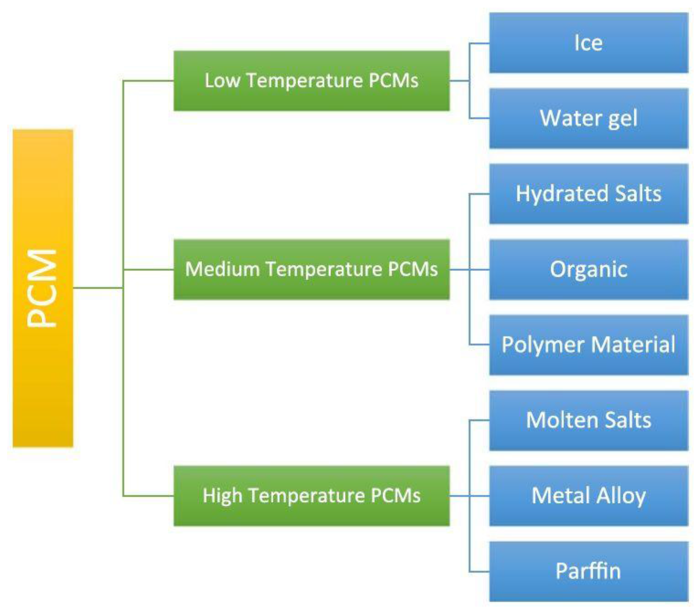
In fact, the temperature range is one of the main criteria for the suitability of a PCM in any application. There are numerous thermal energy storage applications that use PCMs, which all fit a particular range suitable for their optimum thermal performance [
49].
Figure 7 presents a brief classification system based on melting temperatures that, depending on the application desired, can help one decide which PCM to use [
46].
4.1.4. PCM Containment
Containment of PCMs helps contain the material in liquid and solid phases to prevent its possible variation in chemical composition by interaction with its surroundings, to increase its compatibility with other materials in the storage system, to increase its handiness, and to provide a suitable surface for heat transfer. Types of containment studied are bulk storage in tank heat exchangers, macro-encapsulation, and micro-encapsulation. The main characteristic of PCM bulk systems is the need for more extensive heat transfer than that found in non-PCM tanks because the heat storage density of the PCM is higher compared to other storage media. The different approaches extensively used are inserting fins and using high conductivity particles, metal structures, fibbers on the PCM side, direct contact heat exchangers, or the rolling cylinder method [
50].
The two other possibilities are macro- and micro-encapsulating [
51]. Macro-encapsulating consists in including a PCM in a tube, sphere, panel, cylinder, etc. and is the most widespread. The choice of material (plastic or metallic-aluminum or steel) and the geometry affect the thermal performance of the heat storage. Micro-encapsulating consists in a micro-sphere (diameter less than 1 mm) of PCM encapsulated in a very thin and high-molecular-weight polymer. The spheres are then incorporated in some compatible material.
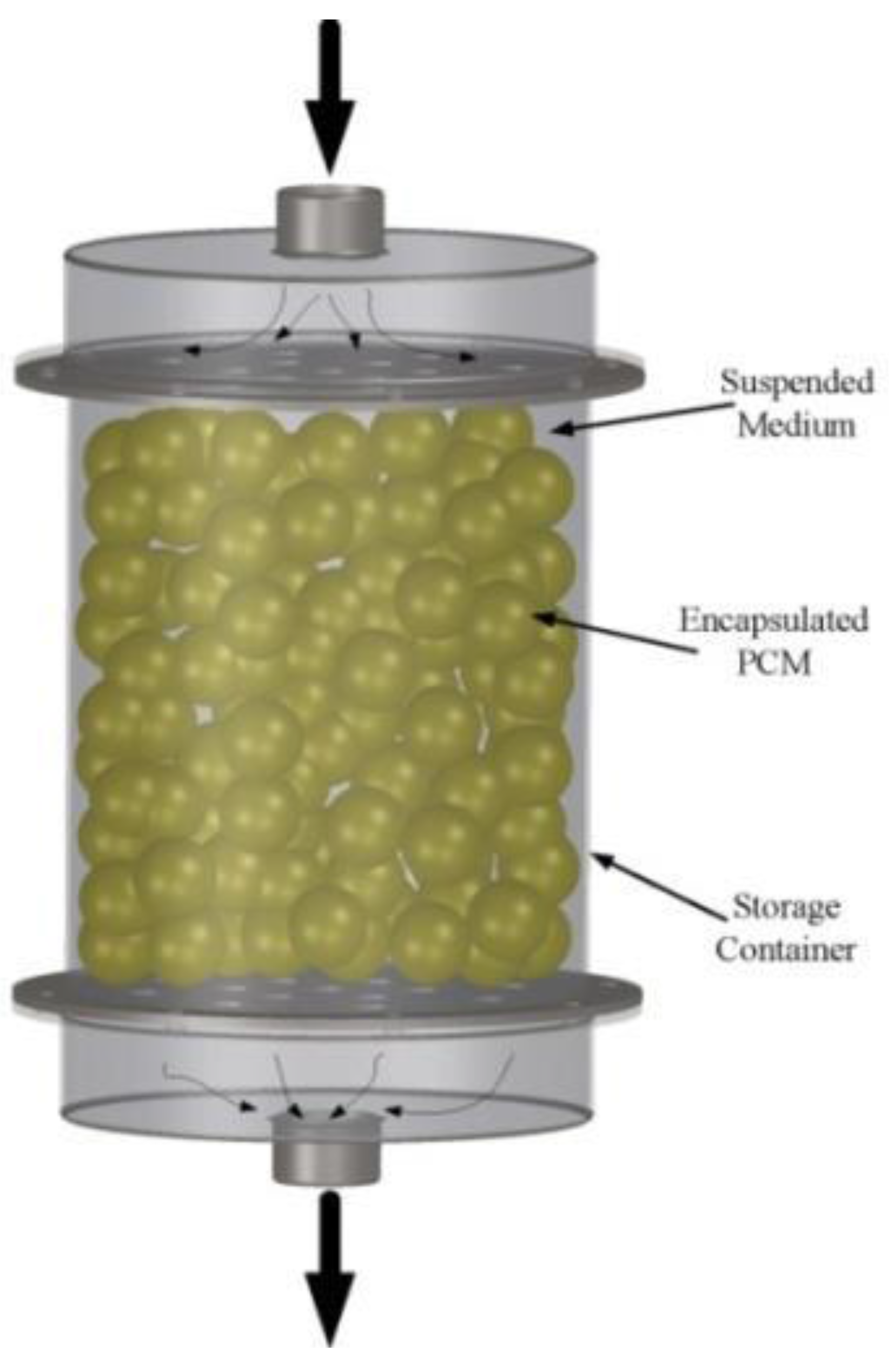
The developed capsules can be used in one-tank TES systems as shown in
Figure 8. The heat is transferred to or from a heat transfer fluid, as the heat transfer fluid flows through the space between the capsules. During the charging mode, the hot fluid from the solar field is circulated through the tank. The PCM inside the capsules absorbs latent heat and melts. During the discharging mode, cooler heat transfer fluid is circulated through the tank to absorb heat from the PCM, causing the encapsulated PCM to freeze. The heated fluid is then used to heat the power block working fluid through a heat exchanger.
PCM encapsulation has been used extensively in building cooling systems where air is passed through flat containers of PCM [
52]. The effect of encapsulated PCM has a good scope in enhancing the performance of LHS systems [
53] used in the solar absorption cooling system.
Organic PCMs can be encapsulated physic-mechanically, chemically, and physic-chemically. Various approaches to prepare the encapsulated PCM (organic) as a new kind of TES medium have been extensively developed and can be manufactured to suit the desired properties [
54].
4.2. PCMs Used for Energy Storage in Buildings
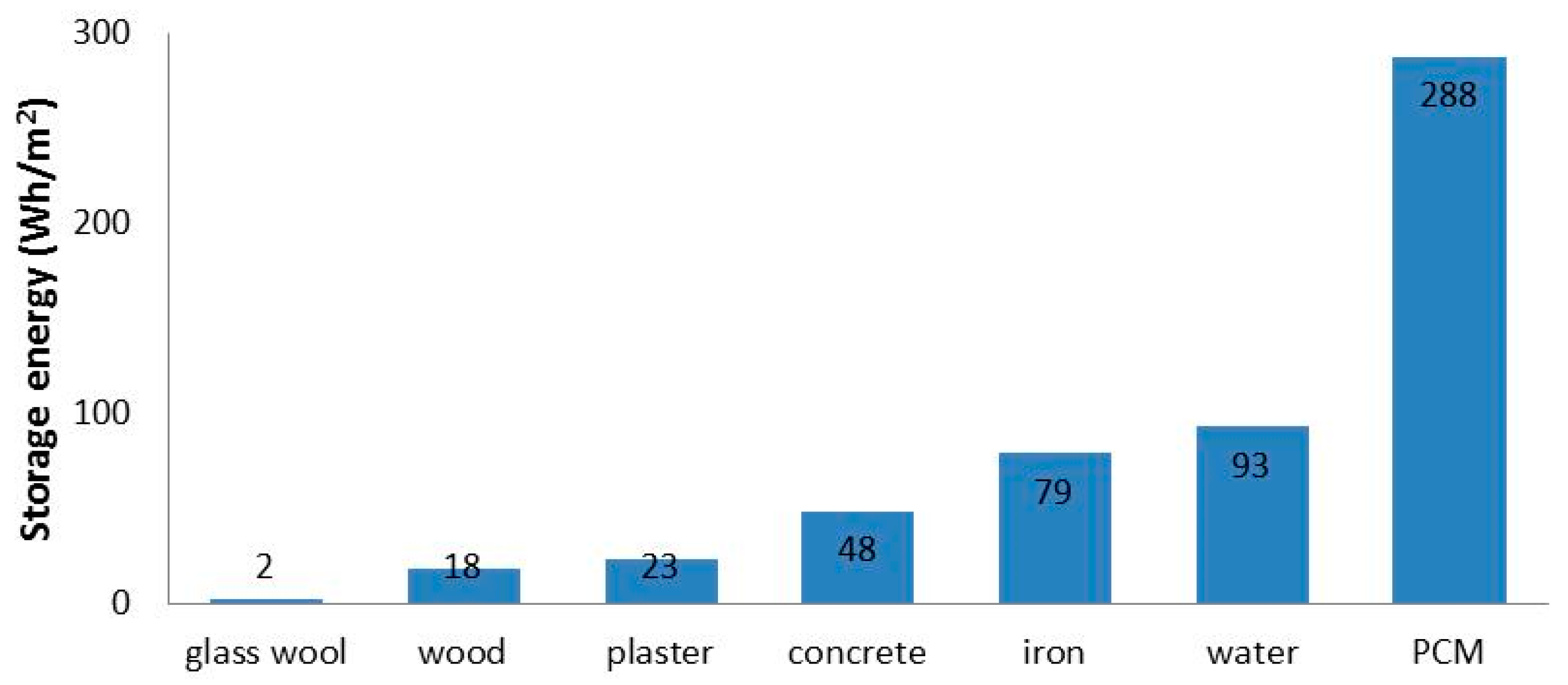
PCMs are considered to be potential energy saving materials since, due to latent heat absorption, they can substantially increase the thermal mass of buildings compared to conventional building materials presented in
Figure 9 [
55].
Storage concepts applied to the building sector have been classified as active or passive systems. Passive thermal energy systems can effectively enhance the naturally available heat energy sources in order to maintain the comfort conditions in buildings and minimize the use of mechanically assisted heating or cooling systems.
The use of active thermal energy systems provides a high degree of control of the indoor conditions and improves the way of storing heat energy. These systems are usually integrated in buildings to provide free cooling or to shift the thermal load from on-peak to off-peak conditions in several applications, such as DHW applications [
56] and heating, ventilation, and air-conditioning (HVAC) systems [
57].
4.2.1. Passive Technologies
The use of TES as a passive technology has the objective of providing thermal comfort with minimal use of HVAC energy. When high thermal-mass materials are used in buildings, passive sensible storage is the technology that allows for the storage of a high quantity of energy, providing thermal stability inside the building. Materials typically used are rammed earth, alveolar bricks, concrete, or stone.
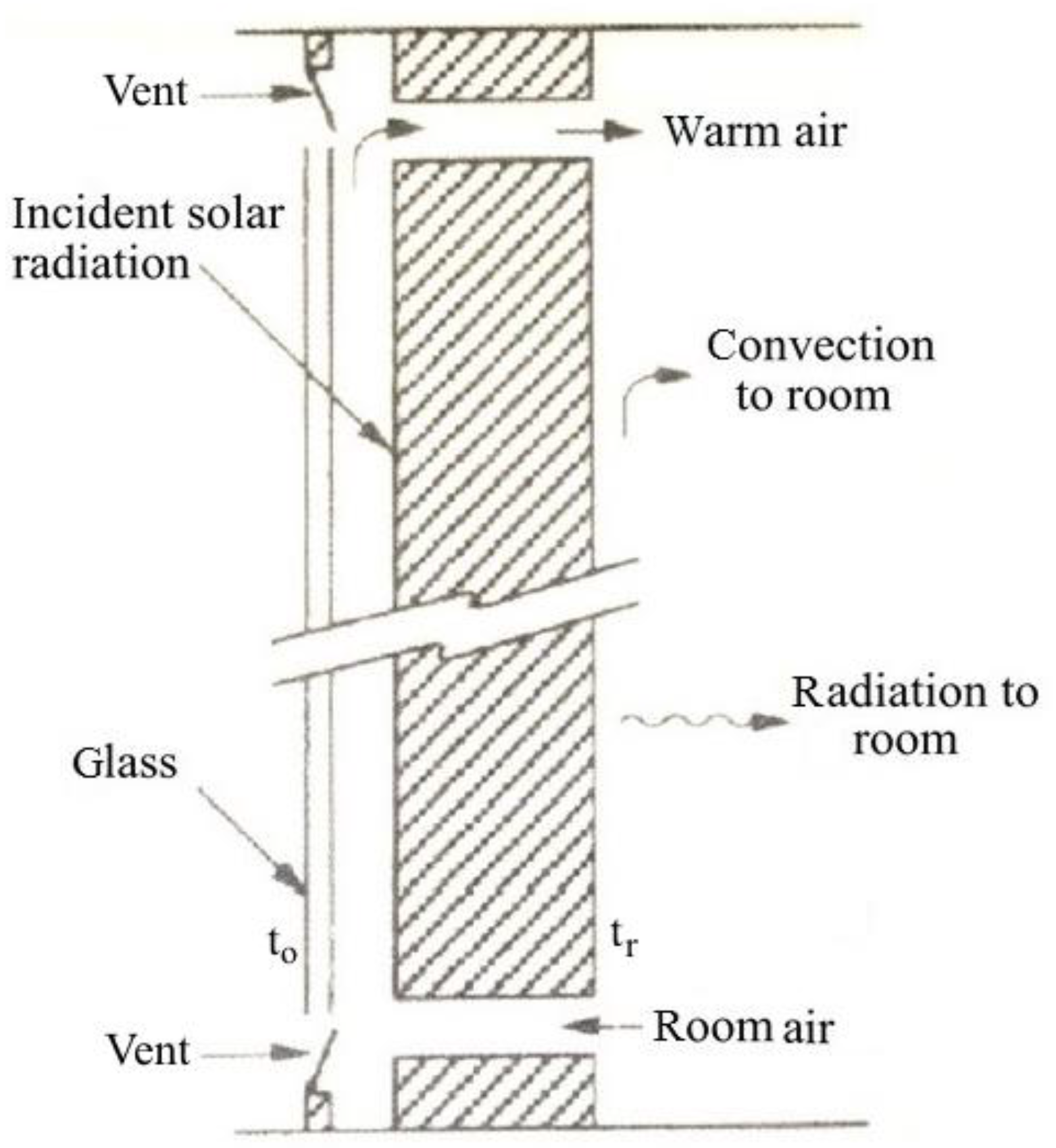
Standard solar walls, also known as Trombe walls, and solar water walls also use sensible storage to achieve energy savings in buildings [
58]. A Trombe wall (
Figure 10) (from the name of the French researcher that first proposed it in 1979) is a wall with high thermal capacity, shielded by a glass pane. A greenhouse effect is created, reducing thermal losses from the wall, heating the air between wall and glass that can be introduced into the room with a natural draught due to the chimney effect of the heated air.
The temperature of the wall increases as energy is absorbed, and time-dependent temperature gradients are established in the wall. Energy is lost through the glazing and is transferred from the room side of the wall to the room by radiation and convection. This storage wall can be considered as a set of
N nodes connected together by a thermal network, each with a temperature and capacitance [
59]. Heat is transferred by radiation across the gap and by convection between air flowing in the gap and the absorbing surface and the inner glazing.
Energy balances are written for each node of thickness Δ
x, resulting in a set of ordinary differential equations with terms that represent its time-dependent temperature and energy flows to all adjacent nodes. The general energy balance for any node
i in the wall is
where λ is the thermal conductivity of wall; ρ is the wall density;
cp is the specific heat of wall;
τ is the time.
Equations for nodes 1 and N must take into account the node half thickness and the convection and radiation heat transfer. The set of N equations are simultaneously solved for the time-dependent temperatures at each of the nodes, and from this the energy stored in the wall (relative to a base temperature troom) can be calculated.
If there is airflow through vents and to the room, the energy added to the room by this mechanism will be macp,a(to − tr), where to is the outer glazing temperature, and tr is the room temperature.
PCM can be incorporated in construction materials using different methods, such as direct incorporation, immersion, encapsulation, micro-encapsulation, and shape-stabilization. In direct incorporation and immersion, potential leakage has to be assessed. When the PCM is encapsulated or added in a shape-stabilized new material, a new layer appears in the construction system of the wall.
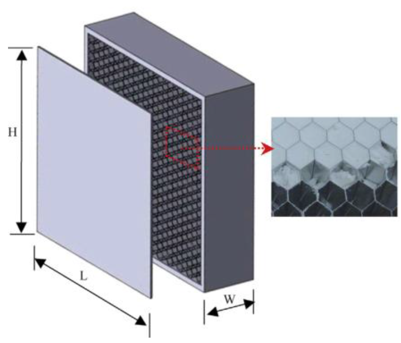
Traditionally, wallboards have been studied as one of the best options to incorporate PCM to building walls. A new approach in PCM-wallboards is the addition of an aluminum honeycomb in containing a micro-encapsulated PCM wallboard (
Figure 11) [
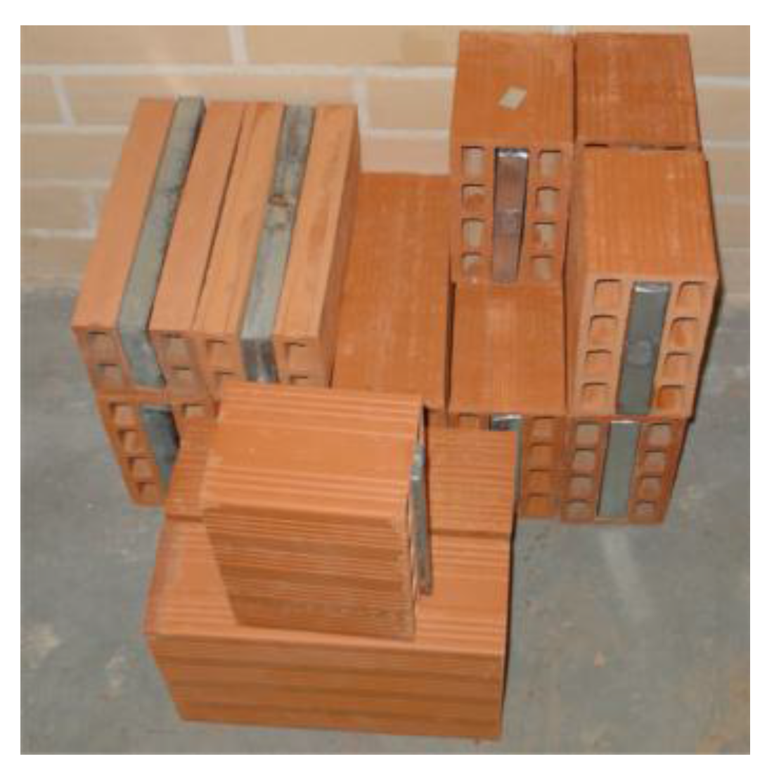
60]. Similarly, PCM can also be impregnated or mixed with concrete or mortar. One of the objectives pursued here is to maintain the concrete mechanical properties while increasing its specific heat capacity. Another approach to incorporating PCM in building walls is to mix it with insulation materials. In a masonry wall, the PCM incorporation can be, for example, within clay bricks (
Figure 12) [
61]. In the PCM shutter concept, a shutter-containing PCM is placed outside window areas. During the daytime, when they are opened to the outside, the exterior side is exposed to solar radiation, heat is absorbed, and the PCM melts. At night, we close the shutter and slide the windows, and heat from the PCM radiates into the rooms.
4.2.2. Active Technologies
The use of thermal energy storage in building active systems is an attractive and versatile solution for several applications for new or retrofitted buildings, such as the implementation of RES in the HVAC for space heating/cooling, improvement in the performance of the current installations, and the possible application of peak load-shifting strategies [
62].
The integration of TES in a building can be done in the building’s core (core, floor, walls), external solar façades, suspended ceilings, the ventilation system, PV systems, and water tanks. One of the main applications of TES in active building systems is the use of free cooling, when the storage is charged with low night outdoor temperatures, and this stored cold is discharged when required by the cooling demand [
63].
Furthermore, TES has been used in building solar systems to convert intermittent energy sources and meet heating and DHW demands. The most popular solar TES method has been extended to integrate solar air collectors in building walls or to use PCM in ventilated façades (
Figure 13) [
64].
Within this context, the utilization of heat pumps with TES systems are presented as a promising technology to shift electrical loads from high-peak to off-peak periods, thus serving as a powerful tool in demand-side management.
TES has great potential as a key technology to reduce the energy demand of buildings and/or to improve the energy efficiency of their energy systems.
Similar to PCMs, the nano-enhanced PCMs can be used in buildings for passive and active applications. In other words, they can be applied to building structures to enhance the overall thermal mass. Additionally, these structures can be used in heating, cooling, ventilation, and air-conditioning systems to reduce the incompatibility between the energy supply and the demand by the shifting and reduction of peak load. Many studies have been carried out on the development of suitable nano-enhanced PCMs for building applications. A summary of the experimental study in this field is listed in
Table 8 [
39].
The combination of PCMs with the solar buildings and zero energy buildings will make a great opportunity for the research and for energy management in buildings.
4.3. Advantages, Disadvantages, and Selection of PCMs
The main advantages of PCM versus water SHSs are [
10]
- −
the possibility of reducing the tank volume for a given amount of energy stored, which can be done only if storage is operated in a very narrow temperature range around the phase-transition temperature, and
- −
fewer on–off cycles of auxiliary heaters (for plants with storage on the hot side) and chillers (for plants with storage on the cold side).
The main drawbacks of PCM versus water SHSs are [
10]
- −
higher investment costs, and
- −
higher risks due to leaks of stability and erosion of material encapsulating PCMs.
These materials make use of the latent heat between the solid- and liquid-phase change and must be encapsulated or stabilized for technical use in any building system, active or passive. This can be achieved via direct inclusion in the wall, by impregnation in a porous material such as gypsum [
74], via micro-encapsulation techniques [
75], or by using a shape-stabilization or slurries of PCM suspended on a thermal fluid [
76]. Encapsulation is a key issue for the implementation of these technologies in buildings and must be designed to avoid leakage and corrosion.
Material selection is the core and most important step in designing LHS. PCM is selected based upon its melting temperature and heat of fusion. The parameters necessary to identify the material include the temperature required for the application and heat requirements. Thus, the type of PCM is selected for its physical and chemical properties, considering the drawbacks. Heat flux DSC is one of the most reliable methods of laboratory thermal analysis for testing heat storage capacity of PCM with a constant heating/cooling rate [
77].
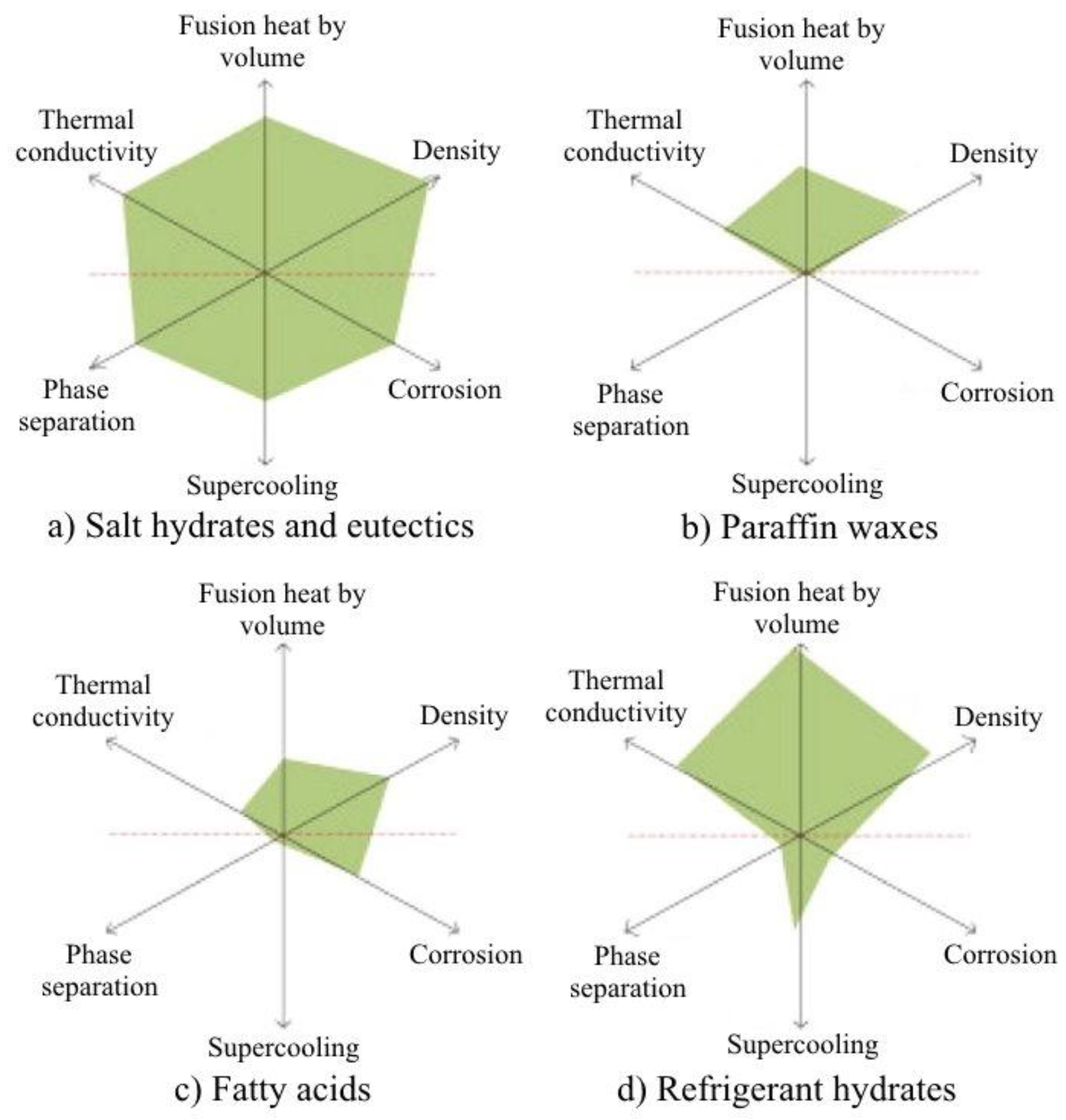
A visual combination of important thermal properties (
Figure 14) of a few types of PCM was produced by Li et al. [
78].
4.4. Thermal Energy Storage for Concentrated Solar Power Plants
CSP systems use mirrors to concentrate sunlight from a large area to a small area, where it is absorbed and converted to heat at high temperatures. The high temperature heat is then used to drive a power block (usually a steam turbine connected to an electrical power generator) similar to the power block of a conventional thermal power plant. A major advantage of CSP plants over solar photovoltaic power plants is that CSP plants may be coupled with conventional fuels and can utilize TES to overcome the intermittency of solar energy.
TES systems can collect energy during sunshine hours and store it in order to shift its delivery to a later time or to smooth out plant output during cloudy weather conditions. Hence, the operation of a solar thermal power plant can be extended beyond periods of no solar radiation without the need to burn fossil fuels. Energy storage not only reduces the mismatch between supply and demand but also improves the performance and reliability of energy systems and plays an important role in conserving energy [
79].
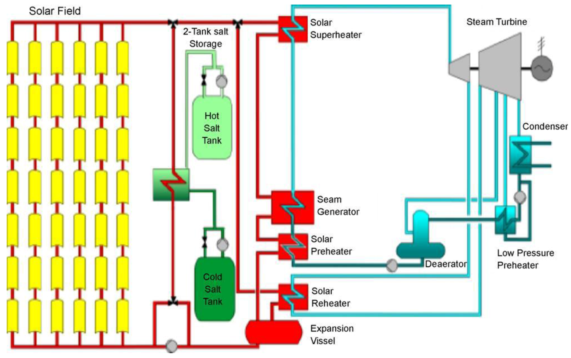
Several TES technologies that have been implemented for CSP plants are mainly two-tank and single-tank systems. In a two-tank system, the fluid is stored in two tanks, one at a high temperature and the other at a low temperature. Fluid from the low-temperature tank flows through the solar collector or receiver, where solar energy heats it to a high temperature and it then flows to the high-temperature tank for storage. Fluid from the high-temperature tank flows through a heat exchanger, where it generates steam for electricity production. The fluid exits the heat exchanger at a low temperature and returns to the low-temperature tank. These systems are called two-tank direct systems. An indirect system, on the other hand, uses different fluids for heat-transfer and storage. An indirect system is used in plants in which the heat-transfer fluid is too expensive or not suited for use as the storage fluid. The storage fluid from the low-temperature tank flows through an extra heat exchanger, where it is heated by the high-temperature heat-transfer fluid. The high-temperature storage fluid then flows back to the high-temperature storage tank. The fluid exits this heat exchanger at a low temperature and returns to the solar collector or receiver, where it is heated back to a high temperature. Storage fluid from the high-temperature tank is used to generate steam in the same manner as the two-tank direct system.
Figure 15 shows a two-tank thermal energy storage system integrated into a parabolic trough power plant [
80].
Single-tank systems, mostly thermocline systems, store thermal energy in a solid medium, most commonly silica sand, in a single tank. At any time during operation, the top part of the medium is at high temperature, and the bottom part is at low temperature. The hot- and cold-temperature regions are separated by a temperature gradient or thermocline. High-temperature heat-transfer fluid flows into the top of the thermocline and exits the bottom at low temperature. This process moves the thermocline downward and adds thermal energy to the system for storage. Reversing the flow moves the thermocline upward and removes thermal energy from the system to generate steam. Buoyancy effects create thermal stratification of the fluid within the tank, which helps to stabilize and maintain the thermocline. Using a solid storage medium and only needing one tank reduces the cost of this system relative to the two-tank systems. This system was demonstrated at the Solar One central receiver CSP system in California, where steam was used as the heat-transfer fluid and mineral oil was used as the storage fluid.
5. Chemical Energy Storage
TCS uses thermo-chemical materials (TCM), which store and release heat by a reversible endothermic/exothermic reaction process (
Figure 2c). During the charging process, heat is applied to the material A, resulting in a separation of two parts B + C. The resulting reaction products can be easily separated and stored until the discharge process is required. Then, the two parts B + C are mixed at suitable pressure and temperature conditions, and energy is released.
The products B and C can be stored separately, and thermal losses from the storage units are restricted to sensible heat effects, which are usually small compared to those of the heat of reaction.
Thermal decomposition of metal oxides for energy storage has been considered [
81]. These reactions may have an advantage in that the oxygen evolved can be used for other purposes or discarded and that oxygen from the atmosphere can be used in the reverse reactions. Two examples include the decomposition of potassium oxide
which occurs over a temperature range of 300–800 °C with a heat of decomposition of 2.1 MJ/kg, and that of lead oxide,
which occurs over a temperature range of 300–350 °C with a heat of decomposition of 0.26 MJ
/kg. There are many practical problems yet to be faced in the use of these reactions.
Energy storage by thermal decomposition of Ca(OH)
2 has been extensively studied by Fujii et al. [
82]. The reaction is Ca(OH)
2 ↔ CaO + H
2O. The forward reaction will proceed at temperatures above ~450 °C; the rates of reaction can be enhanced by the addition of zinc or aluminum. The product CaO is stored in the absence of water. The reverse exothermic reaction proceeds easily.
An example of a photochemical decomposition reaction is the decomposition of nitrosyl chloride, which can be written as
The atomic chlorine produced forms chlorine gas, Cl
2, with the release of a substantial part of the energy added to the NOCl in decomposition. Thus, the overall reaction is
The reverse reaction can be carried out to recover part of the energy of the photons entering the reaction. Processes that produce electrical energy may have storage provided as chemical energy in electrical storage batteries or their equivalent.
Thermo-chemical reactions, such as adsorption (i.e., adhesion of a substance to the surface of another solid or liquid), can be used to store heat and cold, as well as to control humidity. The high storage capacity of sorption processes also allows thermal energy transportation.
Table 9 lists some of the most interesting chemical reactions for TES [
79]. While sorption storage can only work at temperatures of up to ~350 °C, temperatures of chemical reactions can go much higher.
6. Cool Thermal Energy Storage
Cool thermal energy storage (CTES) has recently attracted interest for its industrial refrigeration applications, such as process cooling, food preservation, and building air-conditioning systems. PCMs and their thermal properties suitable for air-conditioning applications can be found in [
76]. For air-conditioning and refrigeration (ice storage), temperatures from −5 to 15 °C are optimum for thermal storage [
8,
83,
84,
85], but at lower temperatures, latent heat storage materials are better than sensible heat storage materials (like water). Some of the commercially available PCMs for cold storage are shown in
Table 10.
CTES appears to be one of the most appropriate methods for correcting the mismatch that occurs between the supply and demand of energy. Cool energy storage requires a better insulation tank, as the energy available in the cool state is expensive, compared to the heat available in a hot storage tank. Cheralathan et al. [
86] investigated the performance of an industrial refrigeration system integrated with CTES. The authors indicated significant savings in capital and operating costs, in thermal storage-integrated systems. The size of the PCM-based CTES system was also considerably reduced when compared with that of a chilled water system. The application of CTES in buildings and in energy systems has many advantages. CTES may play an important role in the management of peak loads and solve the intermittency problem of renewable energy sources, especially when cooling storage is integrated into district cooling systems [
87].
The sorption phenomenon can also be applied for TES. In that case, a heat source promotes the dissociation (endothermic process) of a working pair, whose substances can be stored separately. When they come into contact again, heat is released (exothermic process). Therefore, the energy can then be stored with virtually no loss because the heat is not stored in a sensible or latent form but rather as potential energy, as long as the substances are kept separate.
Typical applications involve adsorption of water vapor to silica gel or zeolites (i.e., microporous crystalline alumina-silicates). Of special importance for use in hot/humid climates or confined spaces with high humidity are open sorption systems based on lithium-chloride to cool water and on zeolites to control humidity.
Adsorption TES is a promising technology that can provide an excellent solution for long-term TES in a more compact and efficient way. Solar thermal energy or waste heat from several processes can be used to regenerate the adsorbent and promote energy storage [
88].
The adsorption cycle has already been used in several research projects to promote TES. In 1990, Kaubek and Maier-Laxhuber [
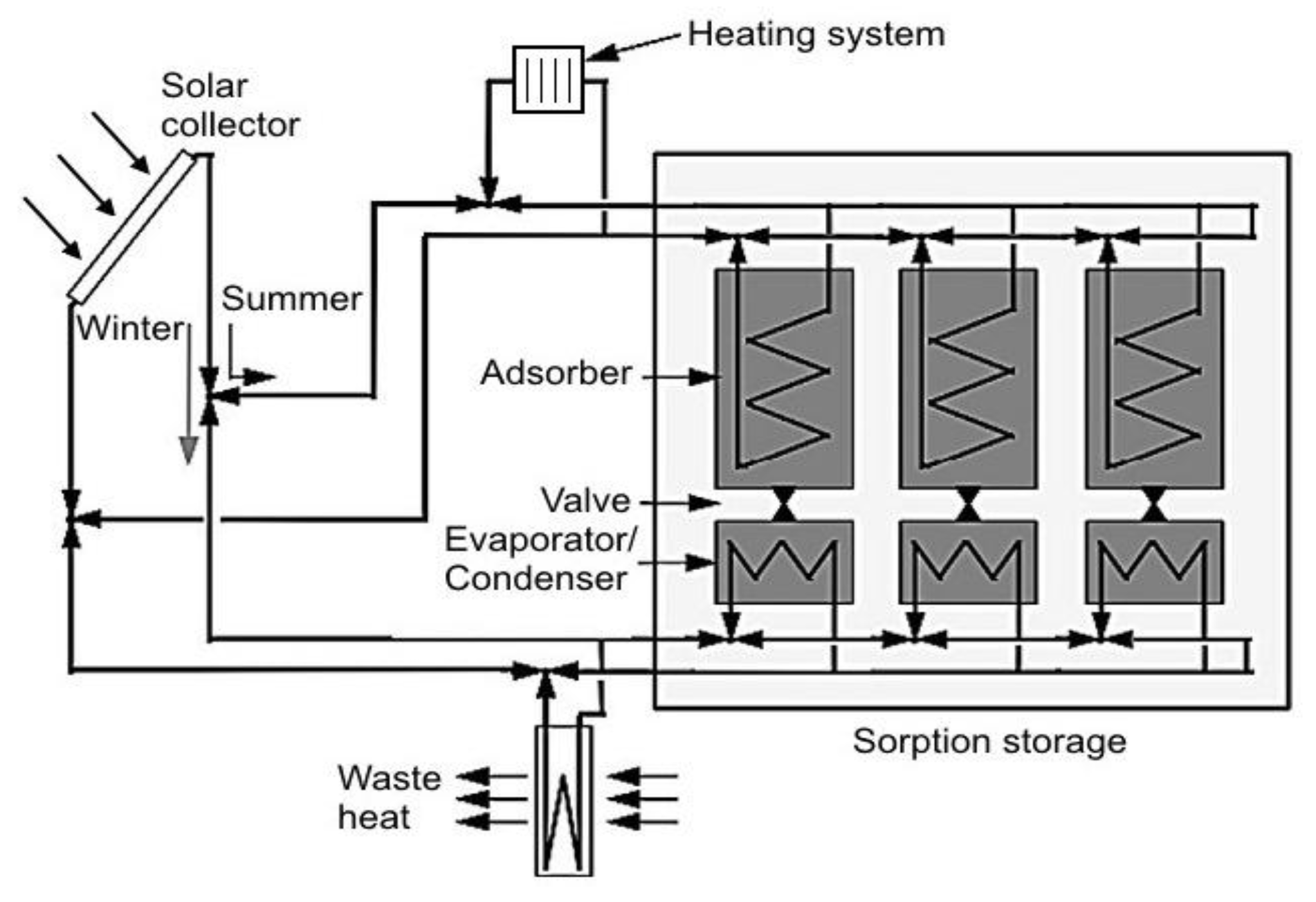
89] patented an adsorption apparatus to be used for electric heating storage, working with the zeolite/water pair and reporting 30% savings in energy consumption. The system can be used as an air-heating device or combined with a hot-water tank. In the first case, the adsorbent bed is heated by electric heating rods during the desorption phase, regenerating the adsorbent and releasing the condensation heat into the space to be heated. In the latter case, the condensation heat is released into a water tank during the desorption phase, while the adsorption heat is transferred to the water tank through a specific closed circuit in the adsorption stage. Hauer [
90] presented a seasonal adsorption TES system, working with the silica-gel/water pair (
Figure 16). During the summer, while the system is charging, the heat from the solar collectors is conducted to three adsorbent beds, promoting the desorption stage. In the winter, the low temperatures in the solar collector promote the evaporation of the water in the evaporators/condensers, and the heat of adsorption is released to the building heating system.
A cascade storage system offers vast potential for the improvement of solar cooling systems. In a cascaded storage system, PCMs with different melting temperatures are arranged in a series to store heat at different temperatures. In comparison with a conventional single PCM-based storage system, a cascaded multiple PCM-based storage system would improve solar collecting efficiency, as the lower temperature at the bottom of the tank is connected to the inlet of the solar collector. The numerical results from the parametric study investigated by Shaikh and Lafdi [
91] indicated that the total energy charged rate can be significantly enhanced using composite PCMs as compared to the single PCM.
Figure 17 shows the different TES technologies: sensible heat (i.e., water as an example), latent heat (i.e., different materials), and thermo-chemical (i.e., sorption and chemical reactions) with respect to their working temperatures [
9].
7. Performance and Cost of TES Systems
TES includes a number of different technologies, each one with its own specific performance, application, and cost.
Important fields of application for TES systems are in the building sector (e.g., DHW, space heating, and air-conditioning) and in the industrial sector (e.g., processes heating and cooling). TES systems can be installed as either centralized plants or distributed devices. Centralized plants are designed to store waste heat from large industrial processes, conventional power plants, combined heat and power plants, and renewable power plants, such as CSP. Their power capacity ranges typically from hundreds of kW to several MW. Distributed devices are usually buffer storage systems to accumulate solar heat to be used for domestic and commercial buildings (e.g., hot water, heating, and appliances). Distributed systems are mostly in the range of a few to tens of kW.
TES systems based on sensible heat storage offer a storage capacity ranging from 10 to 50 kWh/t and storage efficiencies between 50 and 90%, depending on the specific heat of the storage medium and thermal insulation technologies. PCMs can offer higher storage capacity and storage efficiencies from 75 to 90%. In most cases, storage is based on a solid–liquid phase change with energy densities of 100 kWh/m3 (e.g., ice). TCS systems can reach storage capacities of up to 250 kWh/t with operation temperatures of more than 300 °C and efficiencies from 75% to nearly 100%. The cost of a complete system for SHS ranges between 0.1 and 10 €/kWh, depending on the size, application, and thermal insulation technology. The costs for PCM and TCS systems are in general higher. In these systems, major costs are associated with the heat (and mass) transfer technology, which has to be installed to achieve a sufficient charging/discharging power. Costs of LHS systems based on PCMs range between 10 and 50 €/kWh, while TCS costs are estimated to range between 8 and 100 €/kWh. The economic viability of a TES depends heavily on application and operation needs, including the number and frequency of the storage cycles.
Cost estimated of TES systems include storage materials, technical equipment for charging and discharging, and operation costs. Although economic analyses for conventional systems (without thermal storage) [
92] and systems with sensible storage (water) tanks are abundant [
93,
94,
95,
96,
97,
98,
99], comparative cost analyses of using a PCM as a latent heat thermal storage unit in a solar absorption cooling system are rarely seen. Godarzi et al. [
100] designed a PCM storage system based on exergo-economic analysis and a genetic algorithm in a 45.4 kW LiBr/H
2O system. Their analysis showed a payback period of 0.61 years without PCM storage to 1.13 years with PCM storage. Calise [
94] numerically also investigated an LiBr/H
2O system using thermo-economic and optimization techniques, and 64% of primary energy was saved with a payback period of 12 years.
TES systems for sensible heat are rather inexpensive as they consist basically of a simple tank for the storage medium and the equipment to charge/discharge. Storage media (e.g., water, soil, rocks, concrete or molten salts) are usually relatively cheap. However, the container of the storage material requires effective thermal insulation, which may be an important element of the TES cost.
In the case of UTES systems, boreholes and heat exchangers to activate the underground storage are the most important cost elements. Specific costs range from 0.1 to 10 €/kWh [
6] and depend heavily on local conditions.
PCM storage and TCS systems are significantly more complex and expensive than the storage systems for sensible heat. In most cases (e.g., thermo-chemical reactors), they use enhanced heat and mass transfer technologies to achieve the required performance in terms of storage capacity and power, and the cost of the equipment is much higher than the cost for the storage material. The cost of systems using expensive micro-encapsulated PCMs, which avoid the use of heat exchange surfaces, can be even higher.
The difference between the pure PCM and the complete TES system is even higher for active PCM installations. As an example, the costs of a calcium–chloride storage system for heat rejected from a thermally driven absorption chiller includes the cost of calcium chloride, which is rather inexpensive (0.3 €/kg), and the cost of a container, a heat exchanger, and other components around 65 €/kWh [
6].
Materials for TCS are also expensive, as they have to be prepared (e.g., pelletized or layered over supporting structures). Also expensive are the containers and the auxiliary TCS equipment for both heat and mass transfer during energy charging and discharging. TCS systems can be operated as either open systems (i.e., basically packed beds of pellets at ambient pressure) or closed systems. Open systems are often the cheapest option, while closed systems need sophisticated heat exchangers.
The overall economic evaluation of a TES system depends significantly on the specific application and operation needs, including the number and frequency of storage cycles.
TES technologies face certain barriers to market entry, and cost is a key issue. Other barriers relate to material properties and stability, in particular for TCS. Each storage application needs a specific TES design to fit specific boundary conditions and requirements. R&D activities focus on all TES technologies.
TES market development and penetration varies considerably, depending on the application fields and regions. Thus, TES potential for co-generation and district heating in Europe is associated with building stock. The implementation rate of co-generation is 10.2%, while the implementation of TES in these systems is assumed to be 15%. As far as TES for power applications is concerned, a driving sector is the CSP, where almost all new power plants in operation or under construction are equipped with TES systems, mostly based on molten salt. This is perhaps the most important development filed for large, centralized TES installations.
8. Conclusions and Future Trends
SHS is applicable to domestic systems, district heating, and industrial needs. The most popular and commercial heat storage medium is water, which has a number of residential and industrial applications. Underground storage of sensible heat in both liquid and solid media is also used for typically large-scale applications. However, TES systems based on SHS offer a storage capacity that is limited by the specific heat of the storage medium. Furthermore, SHS systems require proper design to discharge thermal energy at constant temperatures.
PCMs can offer a higher storage capacity that is associated with the latent heat of the phase change. PCMs also enable a target-oriented discharging temperature that is set by the constant temperature of the phase change. Melting temperature, latent heat of fusion, and PCM thermo-physical issues are three basic factors influencing the selection of PCMs in any application. A high heat of fusion and a precise melting/solidification temperature (without subcooling) are two primary requirements in the selection approach. Numerous mechanical and nano-level enhancements have been achieved to increase the heat transfer rate, which is promising. Micro-encapsulation increases the heat transfer surface area and is also a solution for phase segregation in salt hydrates.
Most of the literature is focused on routine and commercialized PCM materials such as paraffin. We recommend focusing on special PCMs with a wide temperature range such as salt hydrates and synthesizing specialized PCMs suitable for specific building applications.
TCS can offer even higher storage capacities. Thermo-chemical reactions such as adsorption can be used to accumulate and discharge heat and cold on demand and to control humidity in a variety of applications using different chemical reactants.
In CTES, materials with subzero temperatures are identified, but their thermal reliability, phase-segregation and subcooling issues have not been deeply studied. Studies on industrial (large scale) level thermal cold storage PCMs are hardly tested.
At present, TES systems based on sensible heat are commercially available, while TCS- and PCM-based storage systems are mostly under development and demonstration.
Support for the R&D of new storage materials, as well as policy measures and investment incentives for TES integration in buildings, for industrial applications, and for variable renewable power generation, is essential if its deployment is to be fostered. In future greenhouses, TES solutions can combine heating–cooling–dehumidification functions and provide poly-generation possibilities. Further research on the possibility of thermo-chemical energy storage and the further development of PCMs is needed for this option to be widely adopted in a more cost-effective manner.


