1. Introduction
Climate change is one of the major challenges of the 21st century, with greenhouse gas (GHG) emissions reaching unprecedented levels. Among the most polluting sectors, transport accounts for almost 25% of global CO
2 emissions, mainly due to thermal vehicles powered by fossil fuels [
1]. This dependence on traditional fuels aggravates not only global warming but also air pollution, with direct consequences for public health and ecosystems. An urgent transition to clean mobility solutions is therefore needed to comply with international agreements, such as the Paris Agreement, and limit global warming to 1.5 °C by 2050 [
2].
In this context, electric vehicles (EVs) are emerging as a promising solution for decarbonizing the transport sector [
3]. By leveraging renewable energies and advanced storage technologies, EVs offer a zero-emission alternative for use and significantly reduce carbon footprints compared with those for combustion engines [
4]. However, their widespread uptake remains dependent on the development of high-performance recharging infrastructures that combine energy efficiency and battery preservation [
5]. Particular attention needs to be paid to optimized charging strategies, capable of reconciling speed, battery durability, and harmonious integration into power grids, while meeting the international safety and interoperability standards [
6].
These infrastructure challenges are inextricably linked to user adoption, as the mass deployment of EVs hinges on resolving the perceived limitations of autonomy and recharging times. Expectations are focused on fast charging, which is essential for competing with combustion-powered vehicles and meeting the needs of professional transport fleets [
7,
8].
While fast charging effectively mitigates range anxiety, its implementation presents complex technical compromises—particularly between charging speed and long-term battery preservation [
9]. These trade-offs manifest in several critical challenges: accelerated battery degradation from high current loads, increased peak demand on power grids requiring sophisticated energy management, and the need for backward compatibility with existing charging infrastructure. In response, recent research has focused on developing optimized charging strategies that integrate breakthrough technologies like high-power wireless energy transfer and artificial intelligence (AI)-driven adaptive control systems. These hybrid approaches demonstrate how combining speed-oriented protocols with battery-health-conscious algorithms can simultaneously achieve rapid charging while maintaining system efficiency and durability [
10], offering a comprehensive solution to these competing demands.
This paradigm shift toward intelligent hybrid systems is epitomized by wireless power transfer (WPT), which transcends the technical trade-offs by merging high-efficiency charging with seamless user experiences. WPT is emerging as an optimal solution for accelerating the adoption of EVs, combining charging simplicity (contactless charging) and enhanced safety (no handling of voltage-carrying cables) [
11]. Scientists are taking particular interest in this, as demonstrated by recent advances in energy efficiency and integration into urban infrastructures [
12]. Standards such as SAE J2954 [
13] play a key role in guaranteeing interoperability between all types of vehicle, from urban cars to commercial vehicles, with power ratings from 3.7 kW to 22 kW while ensuring the optimum adaptation to the varied needs of users.
Figure 1 illustrates a wireless charging system composed of two key sub-assemblies: (1) the primary part or the Ground Assembly, integrating coils powered by the traditional electrical grid and/or renewable sources (solar, wind), and (2) the secondary part or the Vehicle Assembly, comprising the coils on board the vehicle [
14,
15]. Energy transfer is performed wirelessly via a high-frequency magnetic field of 85 kHz generated by magnetic resonance, in compliance with the SAE J2954 standard for optimized efficiency and safety. This system supports advanced functionalities such as Vehicle-to-Grid (V2G) and Grid-to-Vehicle (G2V), enabling bidirectional energy management, as well as Vehicle-to-Vehicle (V2V), an emerging technology enabling energy transfer between vehicles [
16]. Versatile, this WPT can power not only electric vehicles EVs but also aerial drones, autonomous submarines, and other mobile applications, paving the way for a universal, sustainable energy infrastructure [
17,
18]. In this context, recent research has demonstrated significant progress in wireless in-flight charging for drones, addressing unique challenges distinct from EV applications [
19]. Key innovations include solutions for dynamic mutual inductance disturbances, lightweight receiver design, and constant-power (CP) delivery under large air gaps. Notably, Ref. [
20] proposed a self-oscillating WPT system with autonomous on–off keying modulation (AOKM) on the primary side, eliminating the need for pickup-side DC-DC converters or wireless communication. This approach extends the CP range by 62.4% while maintaining a 73.8 W output at 88.3% efficiency, even under misalignment. Meanwhile, Ref. [
21] systematizes the field by categorizing existing challenges (e.g., fast charging, coil weight constraints) and emerging solutions, such as adaptive frequency tuning and hybrid transmitter topologies. Together, these studies highlight the potential of lightweight, high-flexibility WPT systems to overcome drone endurance limits, with implications for future standardization and cross-application synergies (e.g., shared SAE J2954 frameworks for EVs and drones).
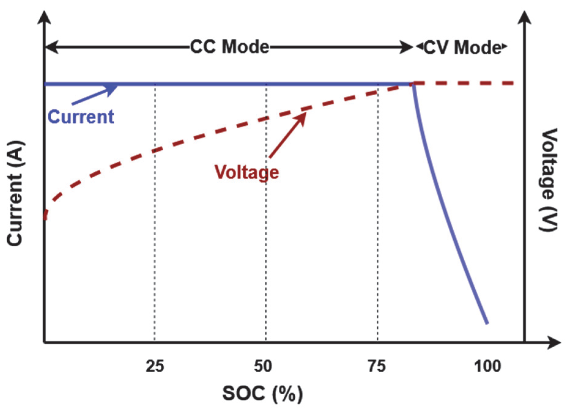
The rapid evolution of EV battery technologies has rendered the traditional charging paradigms increasingly insufficient to simultaneously address critical demands for speed, energy efficiency, and cycle life, underscoring the need for innovative alternatives. The conventional constant-current (CC) and constant-voltage (CV) charging approaches present major limitations in modern EV applications [
22]. In CC mode, high current injection for rapid charging causes excessive cell heating, accelerating cell degradation and shortening the cell life. Switching to CV mode, while limiting overvoltage at the end of charge, results in a significant slowdown of the process, incompatible with the speed requirements of commercial fleets [
23]. These methods are also inflexible in the face of dynamic variations in the operating conditions: they do not adapt effectively to changes in ambient temperature, the battery’s state of health (SOH), or power grid constraints. Moreover, their inability to intelligently manage transient phases between CC and CV modes generates additional energy losses, reducing the overall system efficiency. These limitations have motivated the development of advanced strategies incorporating adaptive algorithms and real-time optimization techniques [
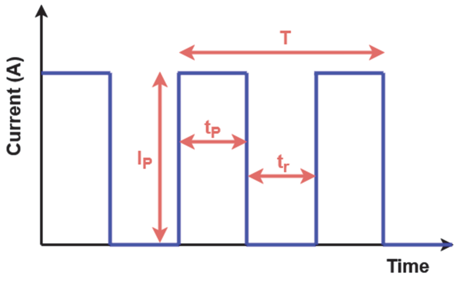
24]. The pulsed current method (PCM) is an innovative method that alternates high-current phases with periods of rest, offering major advantages over the traditional CC-CV methods. Unlike continuous charging, PCM reduces the electrode polarization and limits heat build-up, thus improving the longevity of Li-ion batteries [
25]. Recent studies demonstrate that precisely calibrated lithium insertion kinetics can reduce dendrite formation by up to 40% while extending the cell cycle life by 20–30% [
26]. Further supporting evidence from [
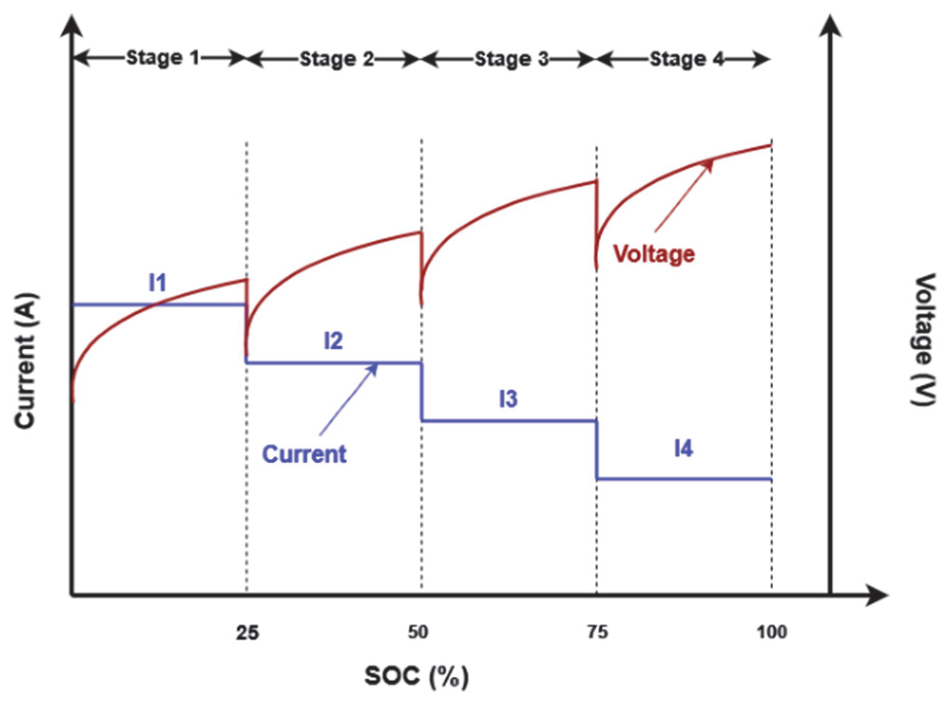
27] shows that PCM significantly improves the performance of Li-ion batteries by simultaneously optimizing their lifespan, charging speed, capacity, and thermal stability. This improvement mechanism operates through two primary pathways: first, by incorporating strategic relaxation phases between current pulses, the PCM mitigates electrode degradation and dendrite nucleation; second, it maintains superior thermal regulation, consistently operating at temperatures 8–12 °C below the conventional CC charging benchmarks. The multi-stage current method (MCM) is an advanced technique for optimizing Li-ion battery charging, particularly in critical applications such as EVs and stationary storage. Unlike traditional CC-CV methods, the MCM dynamically adjusts the charging current in several decreasing steps, offering a better compromise between charging speed, energy efficiency, and preservation of the battery’s SOH [
28]. In [
29], the authors show that for fast charging, the MCM charging technique is an emerging solution for improving the charging efficiency, reducing the temperature rise during charging, increasing the charging/discharging capacities, shortening charging times, and extending the cycle life. However, this method has not been tested for a WPT topology, nor have control strategies to guarantee efficient charging been explored. Also, in [
30,
31], the authors propose an MCM charging strategy for WPT systems, claiming theoretical advantages over conventional CC-CV charging through an improved charging capacity and a reduced charging time in simulations, but they also acknowledge that these findings have not been conclusively verified through experimental validation, highlighting a need for further practical implementation and testing to confirm the proposed MCM-WPT system’s real-world feasibility and performance metrics. The authors in [
30] explore pulse charging for WPT in Li-ion battery systems, proposing it as an alternative to the conventional CC-CV method to improve the efficiency of Inductive Power Transfer (IPT). However, IPT, unlike WPT with magnetic resonance, suffers from low air gap distances, which is not suitable for EVs, and their paper does not specifically respect the SAE J2954 standard with the design.
To apply these charging methods to WPT-based systems, control strategies are essential to drive the charging mechanisms because if any charging mode is applied without a control loop, there is no guarantee that the WPT output will deliver the exact current or voltage required by the charging method. In this context, several approaches to controlling WPT systems have been studied by scientists [
31]. Wireless charging systems can be controlled using three main approaches, each with specific advantages and limitations. Primary-side control offers a simple, cost-effective implementation by limiting itself to transmitter-side sensors but suffers from sensitivity to coupling variations and less precise receiver-side power regulation [
32]. Conversely, secondary-side control enables more precise regulation thanks to direct measurement of the battery parameters and is better suited to dynamic requirements such as V2G, although it requires reliable wireless communication and entails additional costs associated with on-board electronics [
33]. Finally, dual-side control combines the advantages of both approaches, optimizing the efficiency and enabling advanced applications such as Vehicle-to-Everything (V2X), but at the cost of a greater complexity and higher investment [
34]. The choice between these methods thus depends on the application requirements: primary-side solutions are suitable for low-cost systems and secondary control for premium vehicles, while the dual-side approach is essential for high-performance applications requiring bidirectional energy management.
WPT chargers predominantly use the CC-CV method due to its ease of implementation and robustness. However, this approach has limitations in terms of the charging speed and preservation of the battery’s SOH, particularly at high power levels. Although advanced methods such as the MCM and the PCM have demonstrated effectiveness in wired systems for improving both the charge time and battery longevity, few studies have explored their integration into WPT systems, particularly considering the specific constraints related to magnetic resonance and energy efficiency. This gap in the literature motivates our study, which aims to systematically assess the adaptation of the MCM and the PCM to WPT chargers, analyzing their impact on the overall performance and compatibility with existing standards such as SAE J2954.
This paper proposes an innovative charging strategy for static WPT systems dedicated to EVs, articulated around three major contributions. Firstly, we introduce a hybrid pulsed current and multi-stage strategy, combining the advantages of both methods: a pulsed current to reduce battery heating during high-rate phases and the multi-stage profile to dynamically adapt the current steps according to the state of charge (SOC). Secondly, we dynamically optimize the parameters of the PI controller via a memetic algorithm (MA), enabling the gains (, ) to be adjusted in real time according to variations in the magnetic coupling and load. Finally, we integrate an artificial neural network (ANN) for online SOC estimation. These objectives aim to surpass the limits of the conventional CC-CV methods by reconciling fast charging, energy efficiency, and preservation of the battery life, and this reduces the need for frequent replacements, thus limiting the extraction of resources such as lithium and cobalt and the production of new batteries, two highly polluting processes.
The remainder of this paper is structured as follows:
Section 2 introduces the operational principles of WPT systems for EVs and presents the equivalent circuit model.
Section 3 provides a critical review of the conventional charging methodologies, followed by a detailed presentation of our proposed hybrid charging strategy and our ANN-based SOC estimation technique.
Section 4 elaborates on the primary-side controller design methodology.
Section 5 analyzes the simulation results and evaluates the performance metrics of the proposed WPT charging system.
Section 6 presents experimental validation results obtained from a test bench implemented in the ASE laboratory.
Section 7 discusses the key findings and their implications, while
Section 8 concludes this study and outlines directions for future research.
2. The WPT Charger
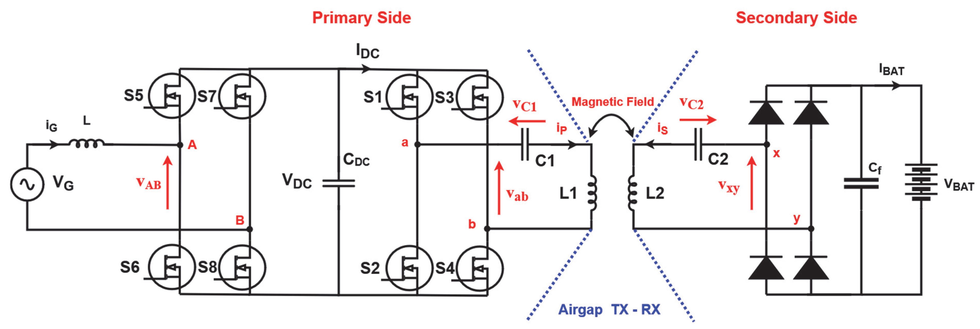
This section aims to outline the fundamental principles of the WPT charger designed for EVs in accordance with the SAE J2954 standard. The system comprises two main components—the primary (ground) side and the secondary (vehicle) side—separated by an air gap, as illustrated in
Figure 2. The ground side includes an inverter that operates at a high frequency of 85 kHz, in compliance with the SAE J2954 standard. Its function is to generate an alternating voltage at the same frequency to energize the primary coil. The latter creates an alternating magnetic flux at the same resonant frequency, which is transmitted wirelessly to the secondary coil. This secondary voltage is now rectified and filtered to supply the electric vehicle’s battery.
In a WPT charger operating through magnetic resonance, compensation capacitors play an important role in optimizing wireless energy transfer. Here are their main functions:
Compensating capacitances ( for primary and for secondary) are added to mitigate the reactive effect of the primary and secondary inductances and , enabling more efficient energy transfer.
For the optimal energy transfer, the system must operate at its resonant frequency:
The capacitors adjust this frequency to match that of the primary 85 kHz excitation signal.
Without compensation, part of the energy would be stored in the magnetic field and not transferred. Capacitive compensation maximizes the quality factor Q of the circuit, reducing losses and improving efficiency.
Among the various topologies employed in wireless magnetic resonance charging systems, the series–series (SS) configuration is one of the most commonly used: unlike other topologies such as series–parallel (SP) or parallel–parallel (PP), SS compensation allows for power stability even if the alignment or the distance between coils varies, and the current in the primary coil also remains stable, which simplifies the regulation.
The analysis and modeling of the system are restricted to the portion between the DC bus and the battery , intentionally excluding the power factor correction (PFC) stage connected to the grid. This simplification is made to focus on the core components directly involved in the WPT process, such as the inverter, the resonant compensation network, the coupling coils, and the rectifier. Including the PFC stage would introduce additional complexity related to grid interaction and AC-DC conversion, which lies outside the primary scope of this study. Moreover, the PFC circuitry does not significantly influence the resonant behavior, control strategy, or power transfer efficiency of the WPT link itself. Therefore, isolating the analysis to the DC-side stages allows for a more targeted investigation of the system’s performance and dynamic characteristics relevant to wireless EV charging.
Equations (2)–(6) present the electrical relationships between the elements that make up the equivalent electrical model of the WPT charger operating under magnetic resonance, where
models the battery’s internal resistance, which is variable during the charging process; this resistance, combined with the
voltage, which is the open-circuit voltage, is used to model the battery of the EV.
where
is the voltage delivered by the high-frequency inverter, and
and
represent the voltages across the compensation capacitors on both sides.
represents the input voltage to the bridge rectifier and
the voltage applied to the battery.
and
are the currents flowing in the primary coil
and the secondary coil
respectively.
represents the mutual inductance between the two coils, ensuring magnetic coupling between the two sides of the charger.
State space modeling simplifies the analysis of WPT systems by representing complex dynamics (resonant circuits, coupling variations) in a compact matrix form, enabling efficient simulation and control design. From the above equations, we can propose a model based on the concept of state space:
where
,
,
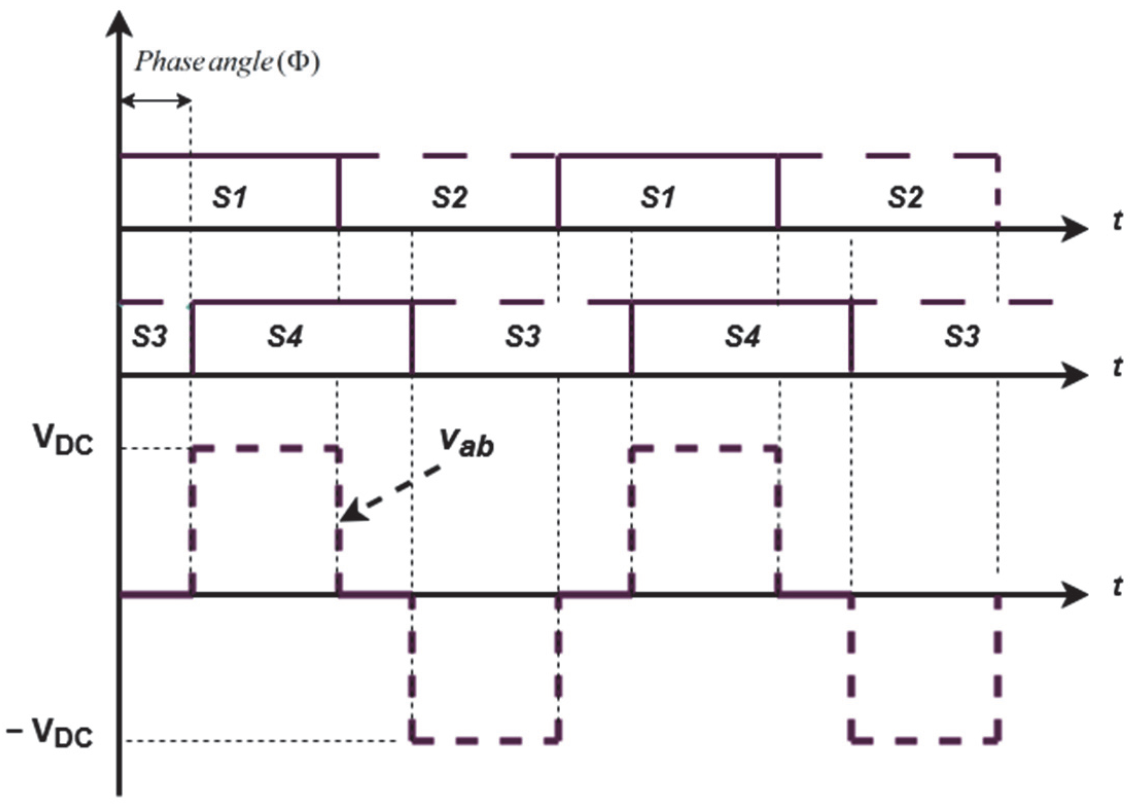
For WPT systems using HF inverters, phase shift control is commonly employed to regulate the output power. On the primary side, the full-bridge inverter generates a square-wave voltage, as shown in
Figure 3, whose output can be expressed as a periodic signal. This square-wave voltage is decomposed into a Fourier series to analyze its frequency components. Since the resonant circuit is designed to operate at a specific resonant frequency of 85 kHz, the fundamental component of the inverter output—at this frequency—is the most significant for power transfer, while the higher-order harmonics are largely attenuated. The phase shift angle
between the bridge legs directly affects the amplitude of this fundamental component. The square-wave output voltage
with the phase shift can be expressed as a Fourier series:
where
is the DC bus’s input voltage;
is the phase shift angle;
is the angular resonant frequency.
Focusing on the fundamental component
, the fundamental output voltage
at the resonant frequency is
4. The Controller Design
This section presents the design of a charge current control loop in a battery using a magnetic resonance WPT charger, combined with a hybrid charging method. The controller used is a PI regulator whose gains (
,
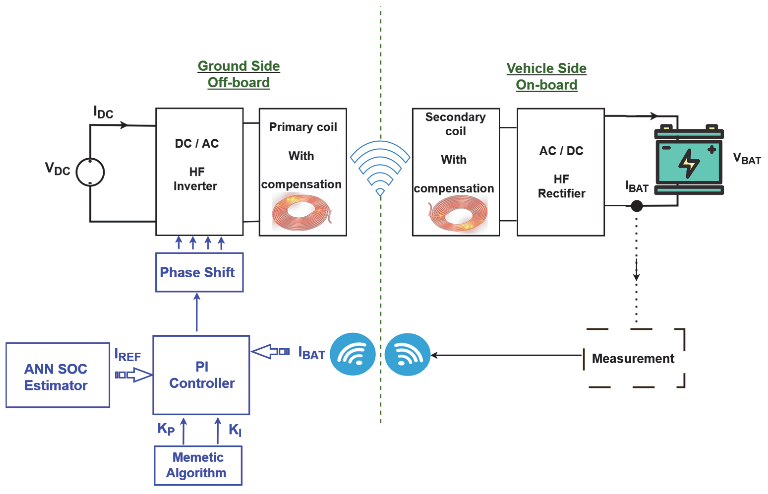
) are optimized in real time via a memetic algorithm (MA), which is a hybrid evolutionary–local algorithm, to adapt dynamically to coupling and load variations. The reference pulsed current is generated as a function of the battery’s SOC, precisely estimated by the ANN. This approach ensures fast, safe, and efficient charging while maximizing the battery life through continuous adaptation of the control parameters. This control technique reduces the complexity on the vehicle side and reduces the EV’s weight by placing the complete control system on the ground side of the WPT system, as shown in
Figure 10. Additionally, the reduction in on-board control circuits reduces the power consumption for such systems, significantly increasing battery autonomy.
In this work, we propose the use of an MA for real-time optimization of the PI gains, offering an innovative solution to the limitations of conventional methods. While many approaches exist to adjusting the PI gains (e.g., Ziegler–Nichols, trial-and-error), they often lack dynamic adaptability in variable environments. Metaheuristic algorithms such as genetic algorithms (GAs) offer a robust performance but are generally too slow for online adaptation due to their computational complexity [
11]. Our solution combines the global exploration power of metaheuristics with fast local operation, enabling real-time adjustment of the PI gains while maintaining a high energy efficiency and preserving battery health. This hybrid approach is particularly well suited to WPT systems, where the load conditions and resonance parameters can vary rapidly.
The MA is a population-based metaheuristic algorithm that effectively balances generality and problem specificity by combining a local exploitation methodology with a global exploration method [
45]. Mesh-adaptive direct search (MADS) and particle swarm optimization (PSO) are coupled in the suggested MA structure.
The primary justification for selecting MADS is its superior randomness performance when compared to that of alternative local exploration techniques. MADS, a local search strategy created for solving multi-objective constraint problems, is different from the traditional direct search methods in that it does not require gradient information about the objective function. Around the first guess, MADS begins its local search process on two kinds of grids: a mesh and a frame. A mesh is a collection of standard grids, while a frame is a collection of randomly selected mesh points. Each iteration of MADS consists of two steps: the search step, which is conducted around the mesh points, and the poll step, which is conducted once the mesh points in the search step have produced no further progress [
46].
Swarm intelligence is used in the PSO approach, a metaheuristic algorithm, to identify the best way to solve a problem. A specific family of evolutionary algorithms known as PSO algorithms employs strategies modeled after the social behavior of birds that search for food in a designated area. PSO is primarily a global optimization strategy, so in order to achieve more precise search capabilities, it must be used in conjunction with a local optimization method [
47].
PSO creates random initial populations and initiates the process through initialization, as seen in
Figure 11. The iteration’s optimal local and global placements are updated following each particle’s evaluation. Following this stage, the subsequent iteration in traditional PSO begins, and the new particles are generated based on their initial positions, initial velocities, and optimal local and global positions. In the MA, however, the next iteration will not start until the best individual has been locally refined. MADS is given by the best individuals from the previous generation as starting points for their quest. MADS is used in the hybrid method to find the local minimum around each beginning point. After MADS, if a better solution can be found, the new individual is accepted as a global solution, and if there is no better answer, the algorithm continues with the method with which its best previous solution was acquired.
Particle velocity and position updates:
where
: The velocity of particle I at iteration k;
: The position (PI gains: , ) of particle i;
: The inertia weight;
: Cognitive/social coefficients;
: Random numbers;
: The personal best for particle i;
: The best global solution.
MADS refines the PSO solutions by polling the points in a mesh around :
: The set of positive spanning directions;
: The mesh size at iteration ;
: The mesh scaling factor.
Update if a poll point yields a better fitness (a lower ITAE for PI gains).
- 1.
The tracking error:
- 2.
Overshoot:
- 3.
The settling time:
- 4.
The control signal:
This function is subject to
5. Simulation Results
This section is dedicated to presenting the simulation results for the WPT charger system, evaluating the performance of the hybrid charging method. The simulation parameters are the same as those used during experimental validation in the laboratory, so as to have the same system operating conditions, all in order to draw constructive and objective conclusions in relation to our proposed approach in this paper. These parameters are listed in
Table 2.
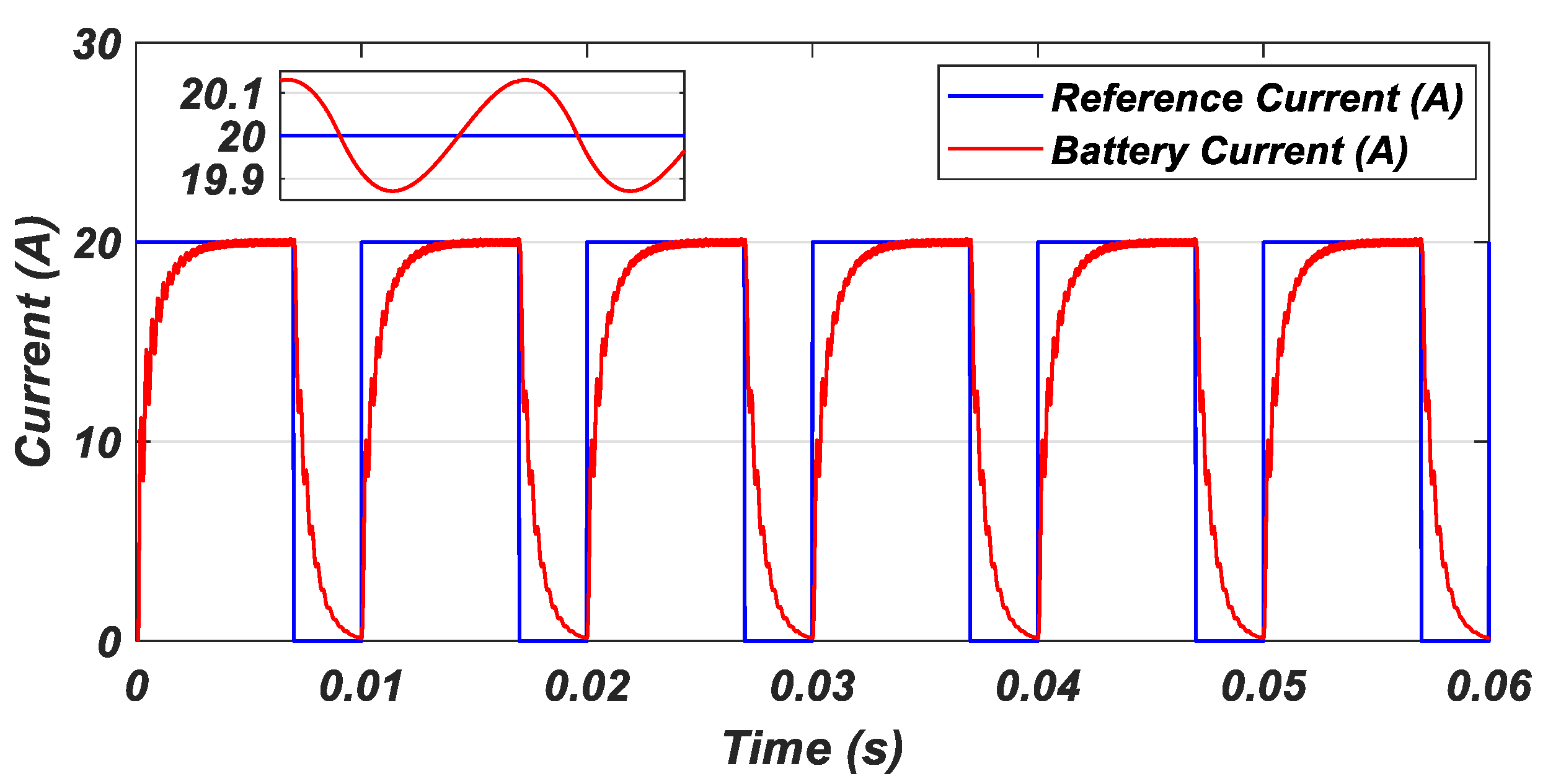
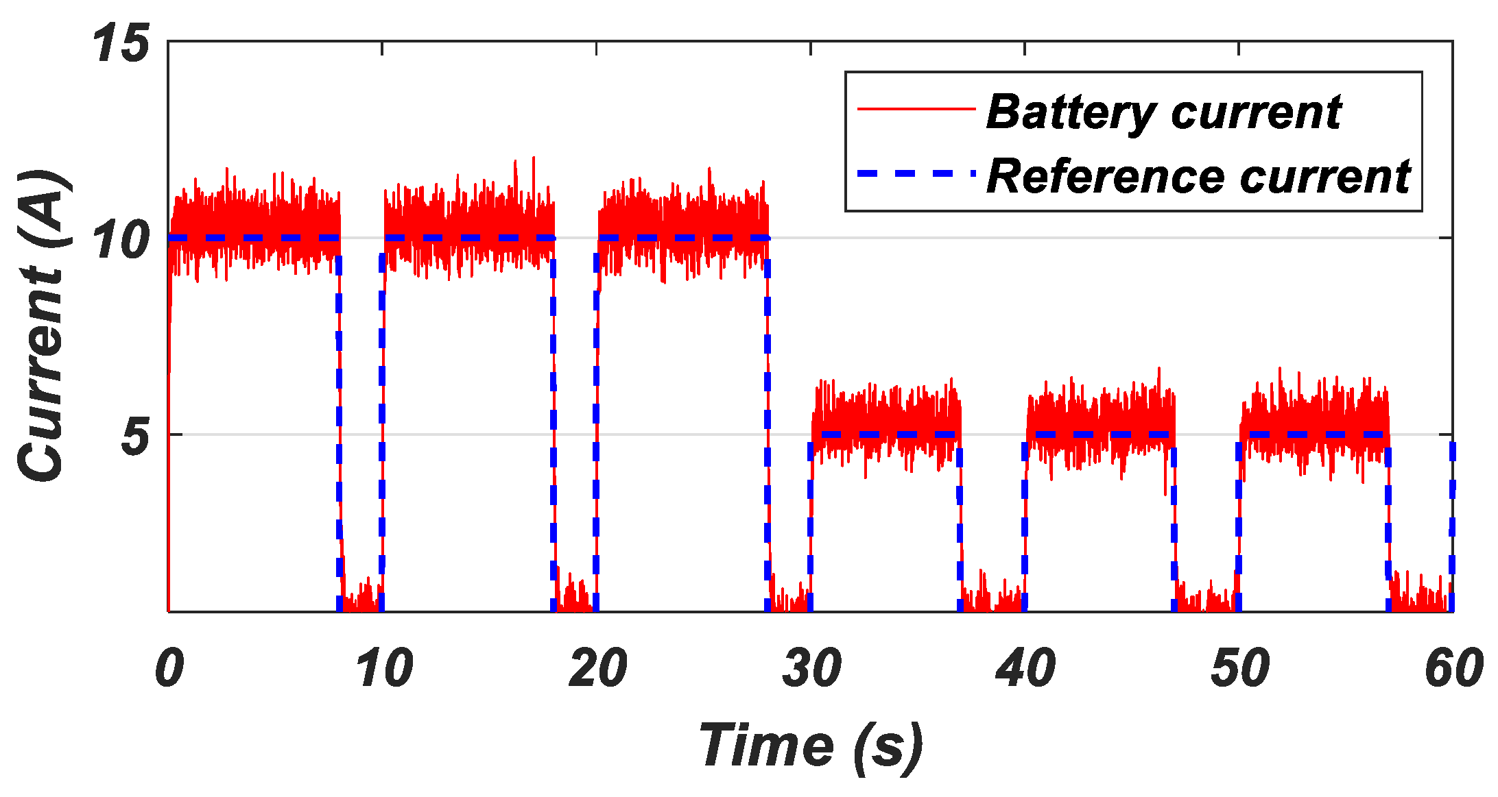
Figure 12 demonstrates the excellent performance of the current regulation system in the WPT charger by comparing the reference current with the measured battery current. The results reveal extremely accurate tracking, with a steady-state regulation error of less than 2% and a fast response time <2 ms during the transitions between the current steps. Particularly remarkable is the overshoot being limited to just 0.5%, testifying to the exceptional stability of the system and the efficiency of the PI controller optimized by the MA. The battery current curve in red faithfully follows the reference current in blue, validating the robustness of the control method and preserving the health of the battery. This performance, in line with the requirements of SAE J2954, confirms that the system is perfectly suited to EV applications, where precise regulation is crucial to reconciling fast charging and durability. This performance is confirmed in
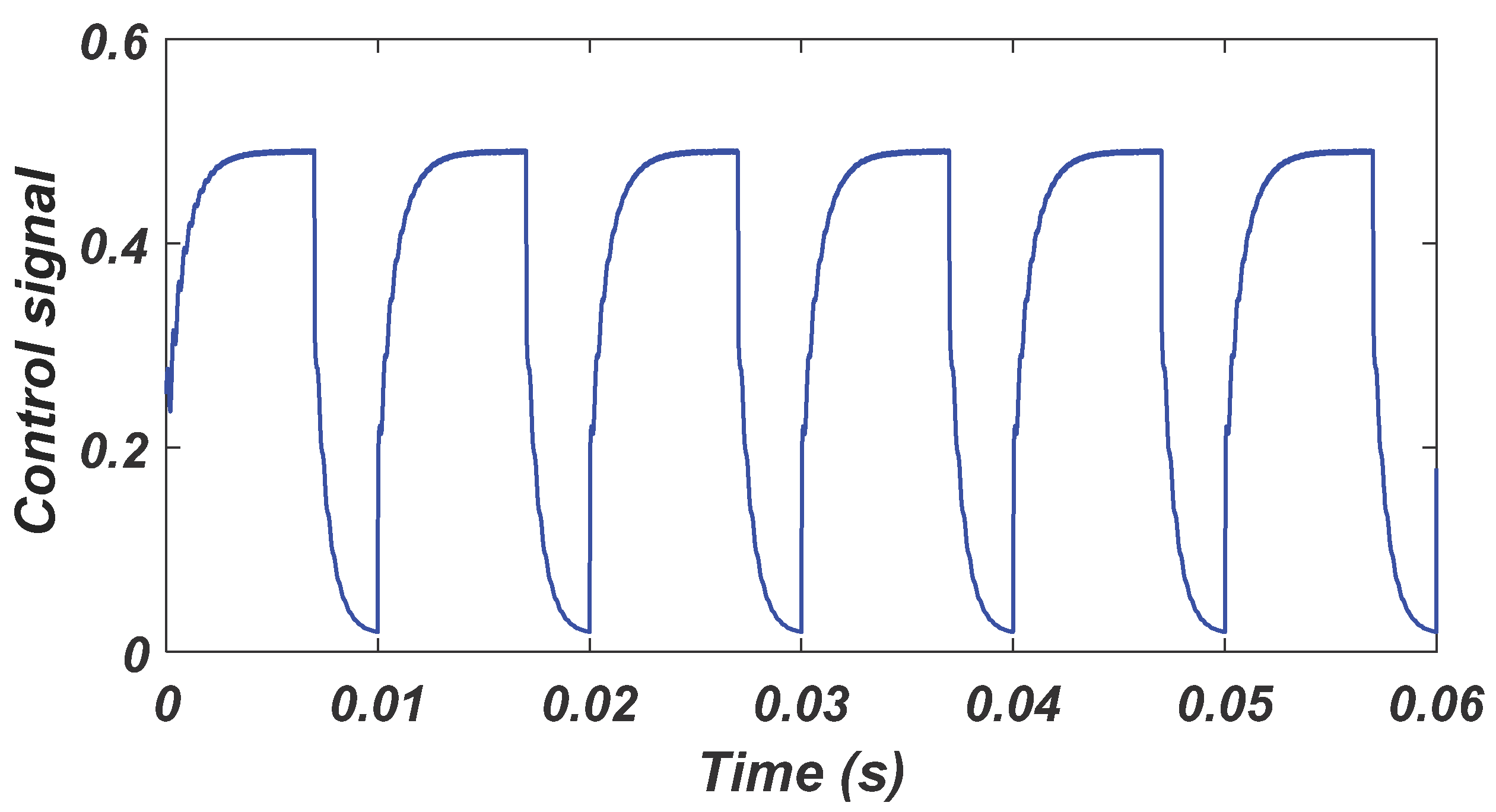
Figure 13, where the control signal dynamically adjusts its amplitude to perfectly match the variations in the reference current, including during transitions. The close correlation between the control signal and the reference current validates the effectiveness of the closed-loop control and the modulation strategy used, guaranteeing a fast response with low oscillation. This performance is reinforced by
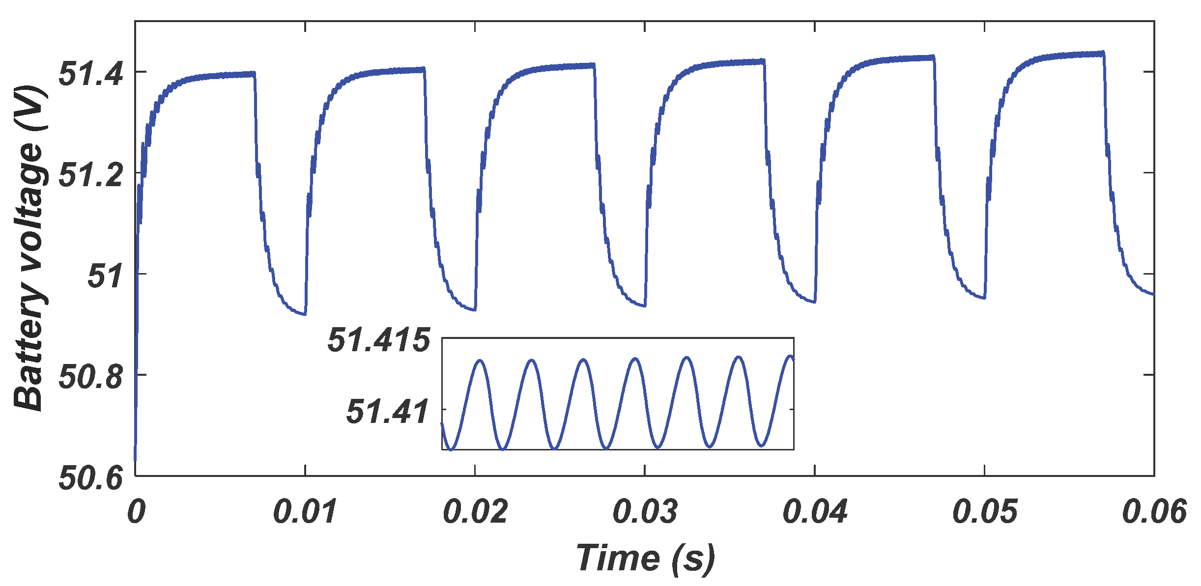
Figure 14 and
Figure 15, which, respectively, illustrate the evolution of the battery’s voltage and the SOC of the battery.
Figure 14 shows a stable voltage progression, with no sudden fluctuations, confirming the absence of electrical stress on the battery.
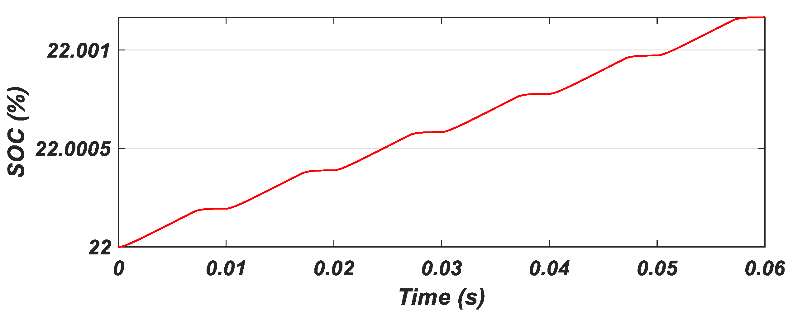
Figure 15 shows an almost linear, controlled growth in the SOC. The absence of abrupt steps in these curves attests to the smooth transition between charging phases.
Now that we have tested the charge control method, we will move on to evaluating the hybrid charging method. The following figures illustrate the performance of this new charging method applied to the WPT charger.
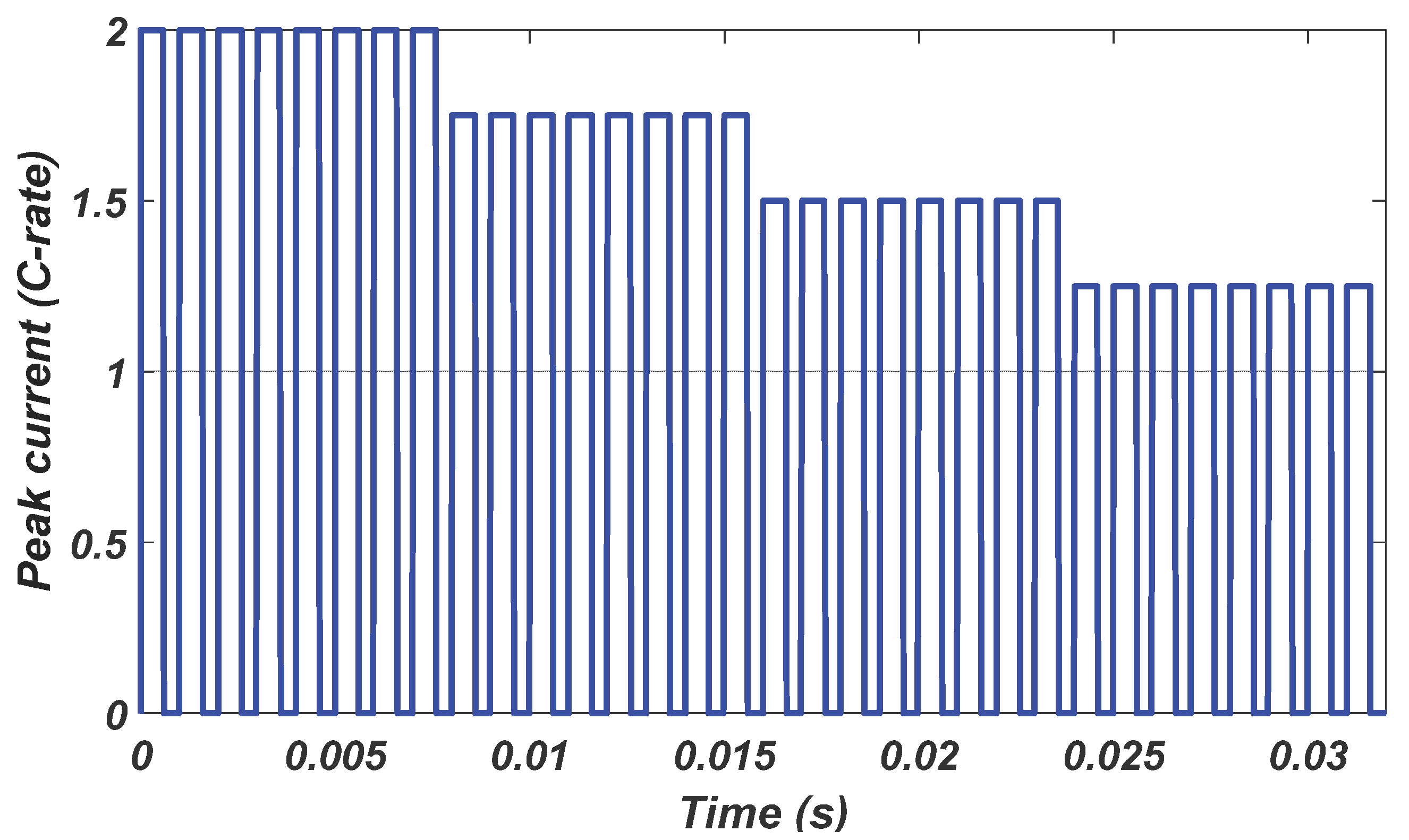
We applied the hybrid method, which consisted of delivering the reference signal that first powered the battery with a current of 20 A, as shown in
Figure 16, as the first stage of the MCM method, but this current was not constant as it is in the MCM method, rather being a pulse current with a frequency of 1 kHz and a duty cycle of 80%. After 0.08 s, we moved on to the second stage, in which a current of 17.5 A was applied but with a duty cycle of 75%. After 0.16 s, the third stage of the method was applied, with a current of 15 A and a duty cycle of 70%, while in the last phase, 12.5 A and a duty cycle of 65% were used. We can clearly see that the MA controller ensures a current that perfectly follows the reference current generated according to the hybrid method protocol applied.
Figure 17 shows the voltage at the battery terminals, and we can see that the voltage also follows the variations in the charging current, with a smooth charging profile and no charging peaks, and despite the very short simulation time of 0.32 s, we can see that the battery’s voltage initially equals 50.95 V and towards the end rises to 51.328 V, which is a very promising result that ensures that the battery can be charged using this method while at the same time protecting it from overheating, which will absolutely extend the battery’s life. The reported simulation time of 0.32 s corresponds to a single charging cycle under steady-state conditions in our model, which is sufficient to capture the dynamic response of the system (e.g., current/voltage stabilization, the SOC estimation accuracy, and controller behavior).
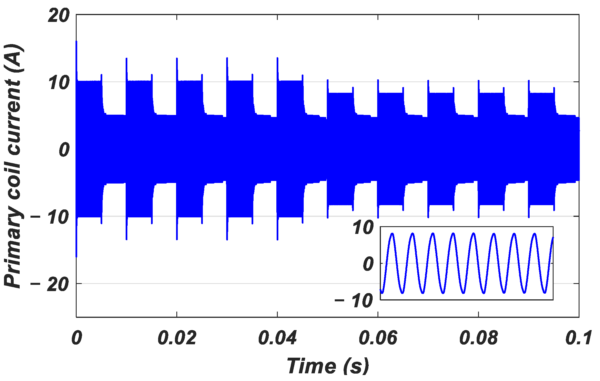
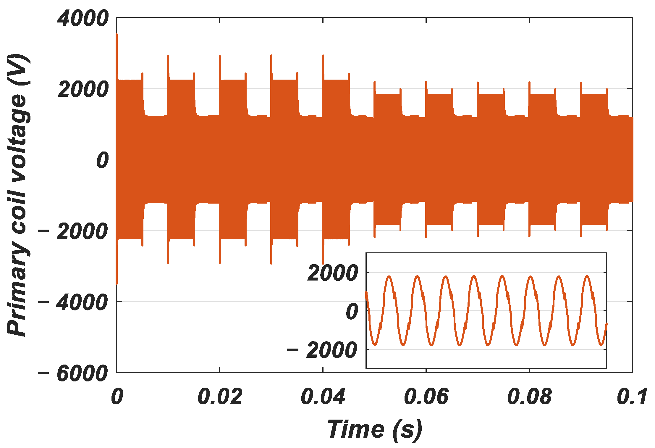
Figure 18 and
Figure 19 show the current in the primary coil and the voltage at the same coil terminals. We can see that the current is sinusoidal due to the resonance because the primary coil associated with the compensation capacitor acts as a bandpass filter at the resonance frequency of 85 kHz. In a magnetic resonance WPT charging system, the voltage across the coils can reach 2000 V even if the input voltage VDC = 200 V, and this is due to the following: At a resonant frequency, the circuit’s frequency becomes almost purely resistive, and the voltage across the coils is amplified by the circuit’s quality factor. This is also due to the series–series topology of the compensation capacitors, which present high voltages [
48].
Figure 20 and
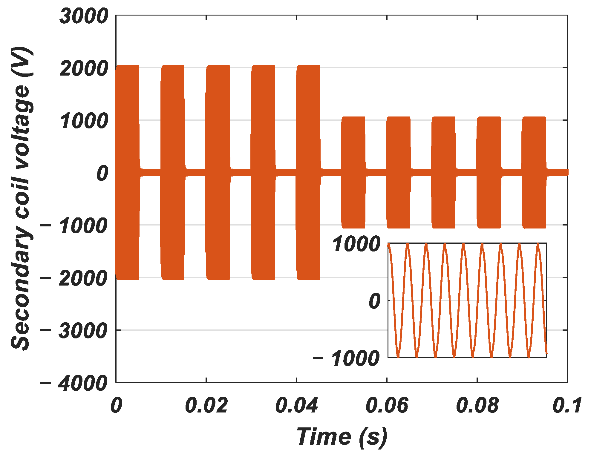
Figure 21 illustrate the voltage and current signals in the secondary coil of the WPT magnetic resonance system of 85 kHz, in compliance with SAE J2954. The voltage has a characteristic sinusoidal shape with an amplitude of 2000 V, as explained earlier for the primary coil, and a frequency corresponding to the system’s resonance, while the current displays a sinusoidal shape that gradually stabilizes during the charging phases. The two signals are quasi-synchronous with φ < 5°, reflecting the optimization of the S-S topology for efficient energy transfer.
Figure 22 and
Figure 23 show the electrical characteristics of the DC bus feeding the inverter on the primary side of the WPT system.
Figure 22 shows the evolution of the DC bus’s input current
, highlighting the fluctuations associated with inverter switching and controller phase shifting. Periodic peaks are observed, corresponding to the transitions of the MCM stages, with gradual stabilization.
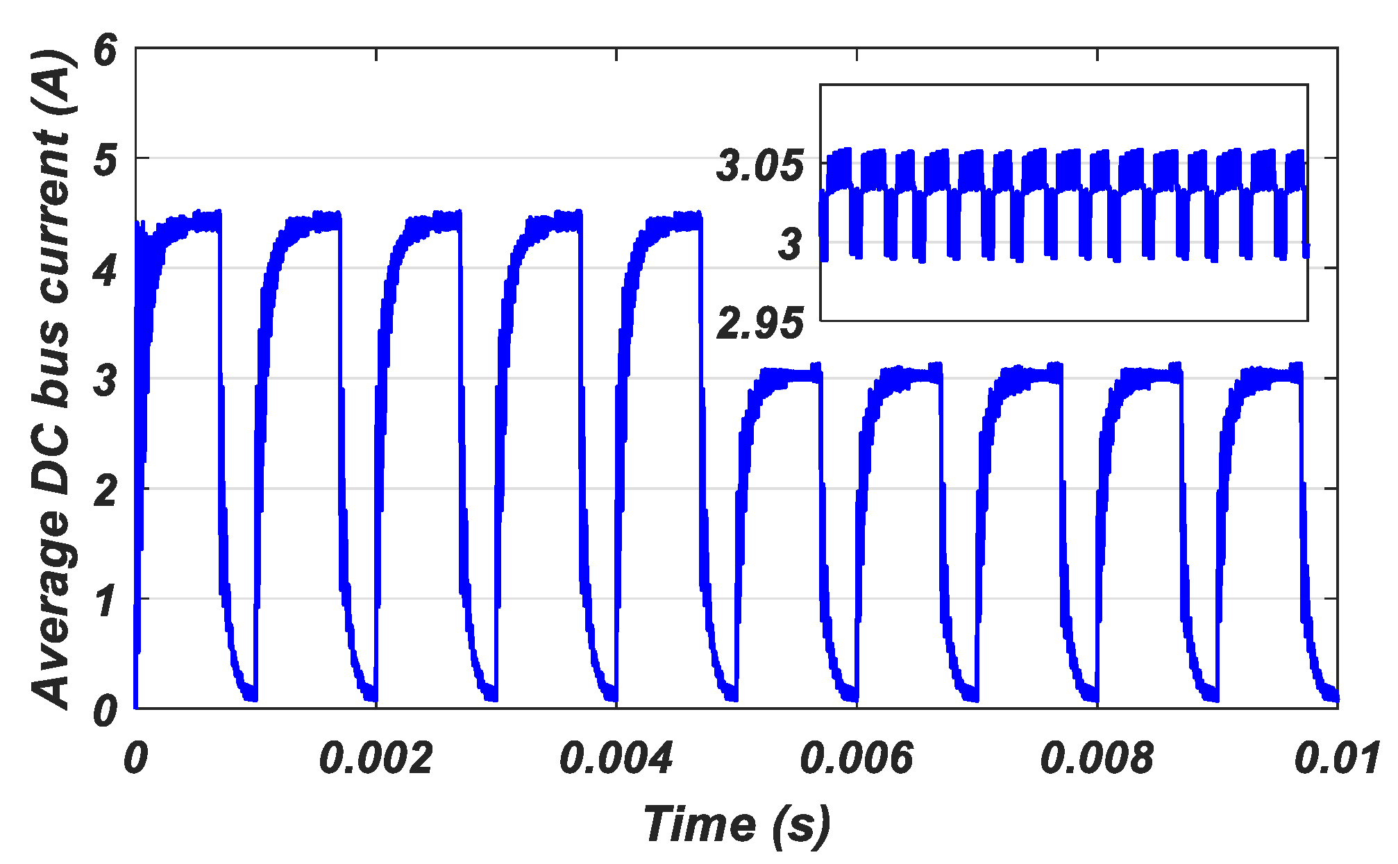
Figure 23 illustrates the average DC bus current
.
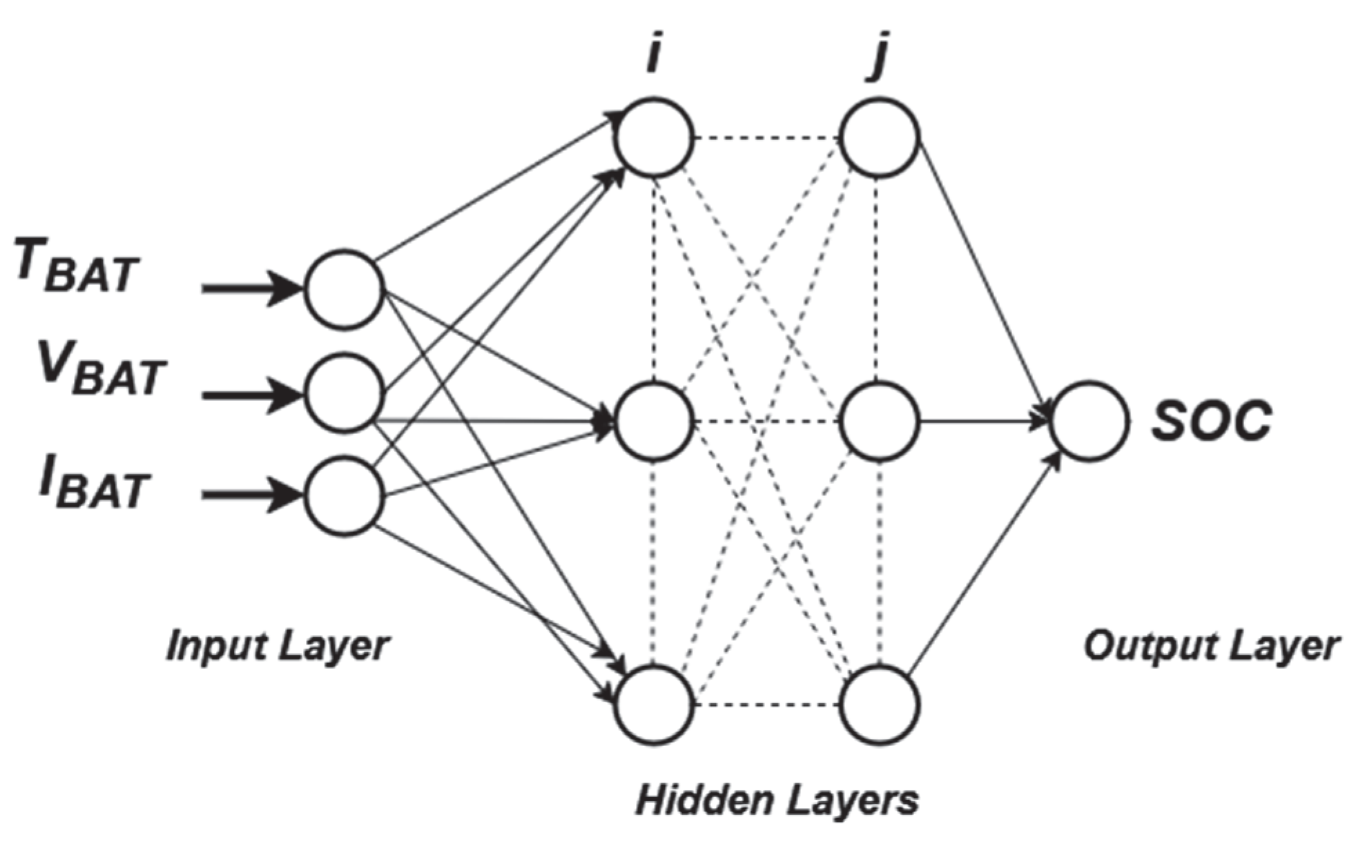
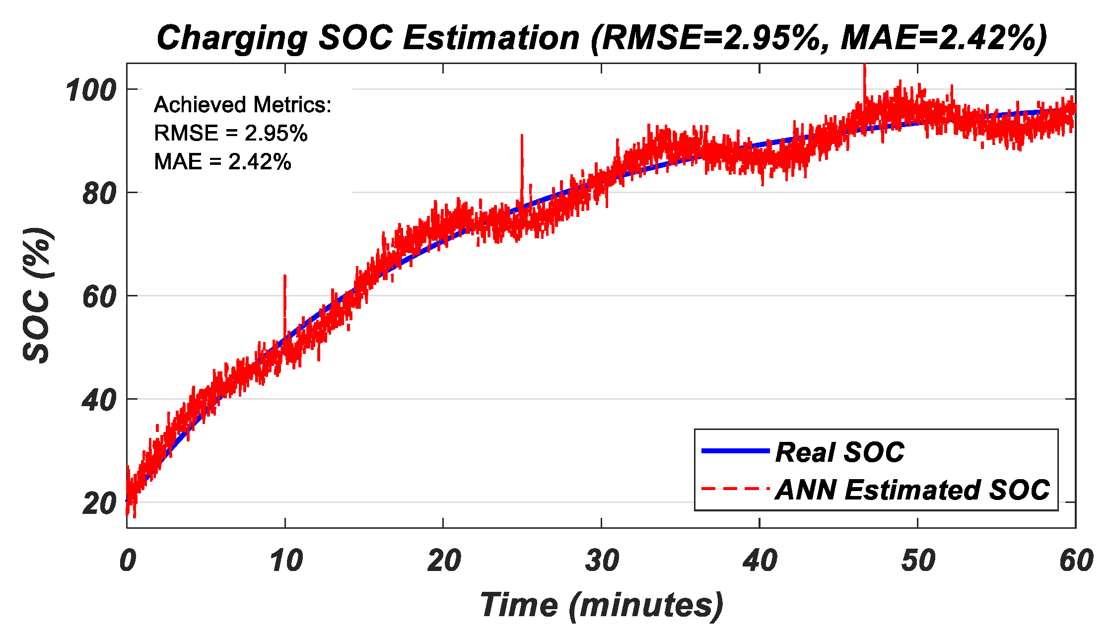
The use of an ANN-based SOC estimator is emerging as a viable alternative to the conventional methods (e.g., coulomb counting, a Kalman filter) due to its ability to capture complex battery nonlinearities (e.g., aging, temperature, hysteresis) without relying on precise electrochemical models. Unlike the traditional approaches, the ANN self-adjusts in real time by learning from historical data, thus eliminating the cumulative errors and drifts common in the coulombic methods.
Figure 24 shows a comparison between the real SOC and the SOC estimated using the ANN, revealing minimal residual error (<3% RMSE), confirming the reliability of this approach. Furthermore, this low-cost solution does not require costly additional sensors, as it exploits measurements that are already available, while offering adaptive accuracy even under dynamic conditions. These advantages make it ideal for on-board systems in EVs, where accuracy and cost-effectiveness are critical.
Precise estimation of the SOC using an ANN opens the way to dynamic control of the PCM-MCM hybrid method, where transitions between the current stages are driven by the actual SOC rather than fixed time intervals. Unlike the traditional time-based approaches (e.g., 10 min at 2 C, then switch to 1 C), the ANN enables real-time detection of the optimal switching point between load stages (e.g., switching from 2 C to 1 C at a precise 70% SOC, not after an arbitrary delay). This adaptability improves both the energy efficiency by avoiding unnecessary overcharging/stress and the battery life by adjusting the currents as soon as the electrochemical state permits.
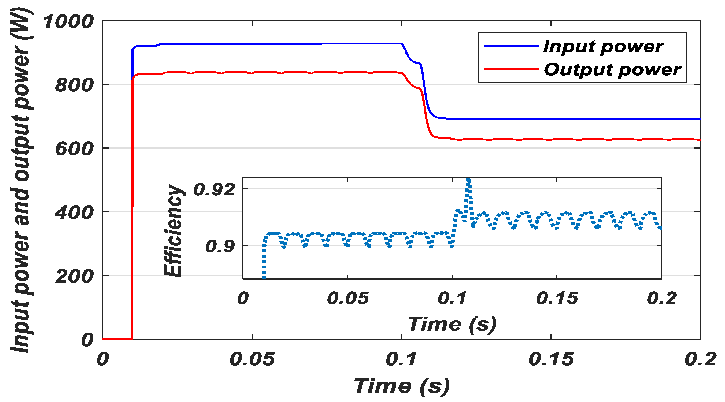
Figure 25 shows the input power transmitted from the primary side and the output power delivered to the battery profiles of the WPT system, highlighting a constant output power proportional to the input power, confirming the stability of the energy transmission. The system’s average efficiency is around 91%, in line with the theoretical expectations for magnetic resonance topologies around 85 kHz. This efficiency remains constant as long as operating conditions such as the mutual inductance, coupling coefficient, and air gap are kept stable. Any variation in these parameters—for example, vehicle displacement modifying the air gap—could alter the efficiency, underlining the importance of precise alignment and adaptive control to guarantee the optimum performance in real-life conditions.
The simulation results presented demonstrate the potential of the MCM-PCM hybrid strategy to improve the efficiency, ensure fast charging, and preserve the batteries in a WPT charger for EVs. However, to confirm this performance and assess the robustness of the system in the face of real constraints, in-depth experimental validation is required. The following section therefore presents the test protocol implemented, including characterization of the chosen hardware, assessment of the robustness of the method, and verification of the controller’s stability under different operating conditions.
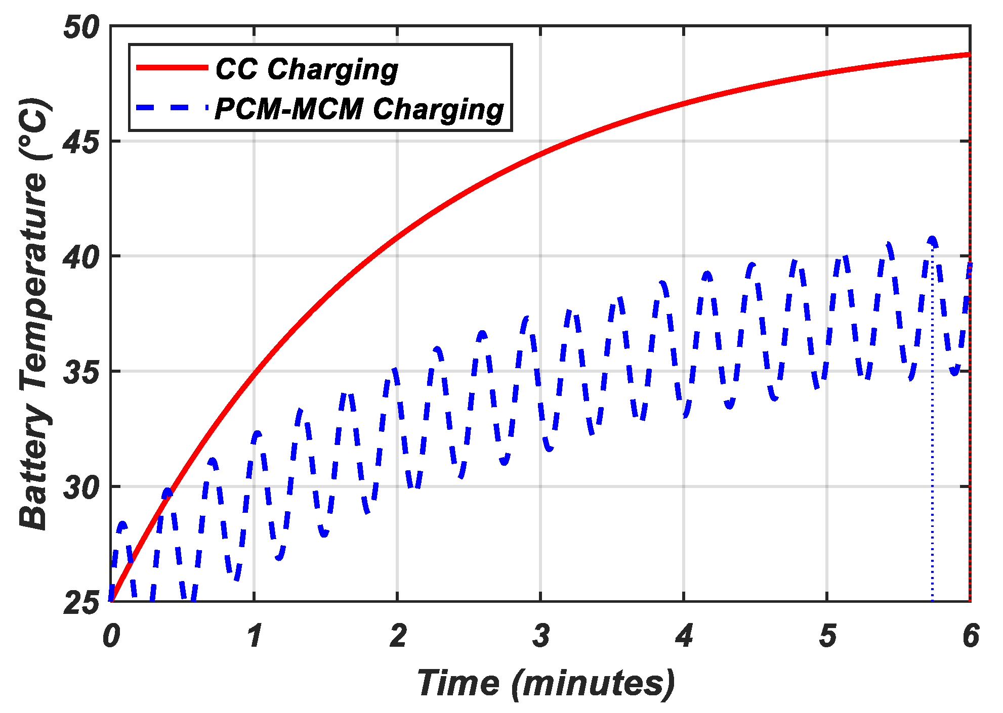
The comparative analysis of the CC mode and the proposed method of charging reveals distinct thermal behaviors: CC charging exhibits a monotonic temperature rise due to sustained joule heating and polarization losses, whereas PCM-MCM introduces periodic cooling during the pulse-off phases, reducing the peak temperatures by 8 °C through convective dissipation and lowered ionic gradients. Our hybrid MCM-PCM strategy optimizes this further by combining multi-stage current limiting (e.g., 2 C only for a 0–50% SOC) with the PCM’s active thermal regulation.
Figure 26 illustrates these regimes, with the hybrid method’s oscillatory profile demonstrating real-time heat management and the hybrid method’s superior equilibrium.
6. Experimental Validation
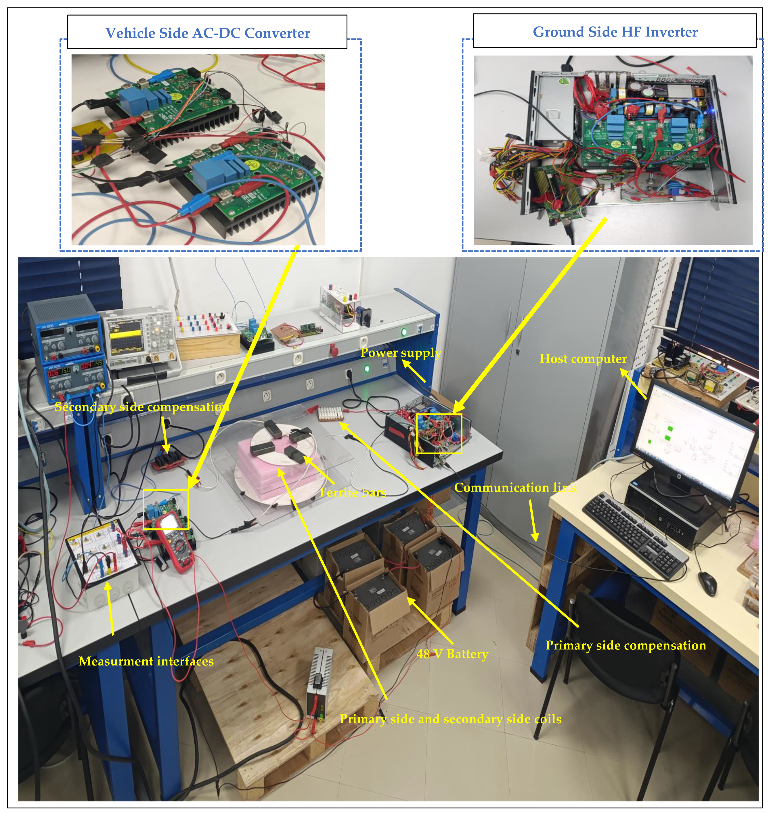
This section presents the experimental results for the MCM-PCM hybrid charging system integrated with a WPT magnetic resonance wireless charger, aiming to validate the system’s energy efficiency in line with the simulations and the performance of PI control optimized by the MA from the primary side. The complete test bench in the ASE laboratory is shown in
Figure 27.
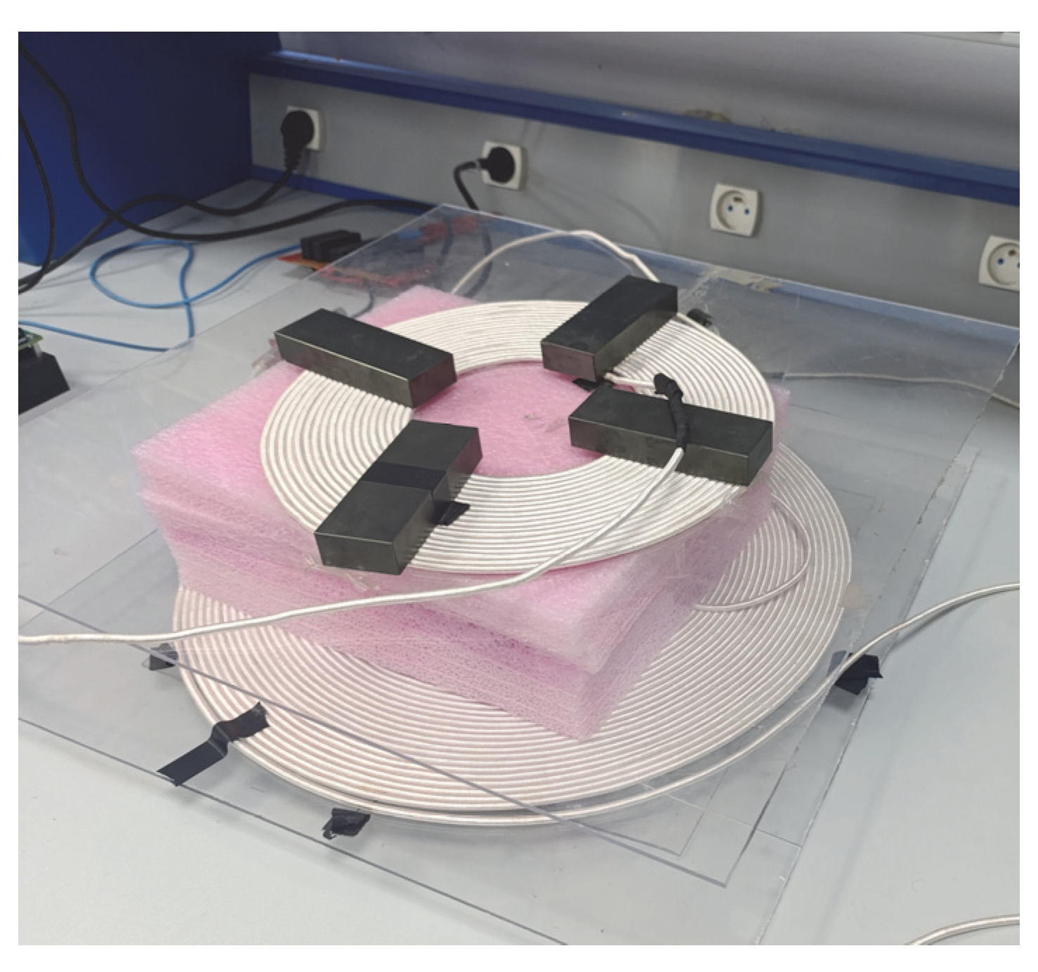
For experimental validation of our 85 kHz magnetic resonance WPT system in compliance with SAE J2954, the primary and secondary coils were made of 1050-strand twisted Litz wire, as shown in
Figure 28, a technically justified choice to meet three major high-frequency challenges. Firstly, the multi-strand configuration of the Litz wire effectively reduces the skin effect at 85 kHz, as the depth of the current’s penetration into the copper is only ~0.23 mm, making the 1050 fine, 0.1 mm diameter, individually insulated strands ideal for minimizing the AC resistance, which is 40% lower than that in a solid wire. Secondly, this design maximizes the quality factor Q > 200 by reducing the proximity losses between conductors, essential for maintaining superior efficiency. Thirdly, the improved surface-to-volume ratio enables better thermal management, keeping the coil temperatures < 50 °C at a high transfer power, which is a key safety criterion for automotive applications. The experimental measurements confirmed stable resonant operation in all charging modes with an impedance variation <5% under a load, validating the Litz 1050-strand wire as optimal for reconciling high efficiency and durability. The twisted strands also reduce the inter-wire capacitance that could detune the resonance at 85 kHz. Ferrite bars were added to effectively channel the magnetic flux, reducing the field leakage and improving the coupling between the primary and secondary coils. Their high magnetic permeability concentrates the field lines at 85 kHz, increasing the energy transfer efficiency while minimizing the electromagnetic interference. The Mn-Zn ferrite cores were sourced from TDK Corporation [
49].
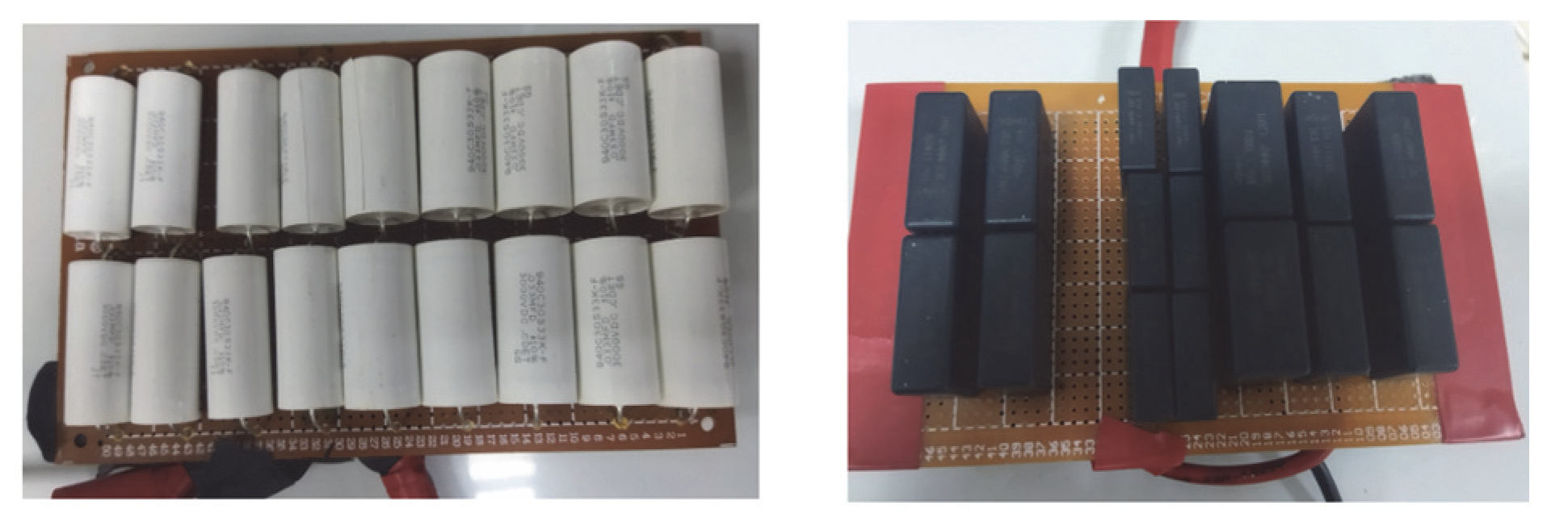
Figure 29 shows the compensation capacitors on the primary and secondary sides, which are essential for the magnetic resonance operation of the WPT charger. The capacitors in this test are S-S-type and are precisely calculated to compensate for the inductive reactance of the coils at a working frequency of 85 kHz, thus creating a resonant LC circuit.
SiC (silicon carbide) and GaN (gallium nitride) transistors represent the best technological choice for power converters in high-frequency WPT chargers thanks to their low switching losses and high efficiency even at high powers. Compared with traditional silicon MOSFETs, they offer better thermal management and a superior performance in high-frequency applications. For these tests, we opted for GaN MOSFETs, as recommended by Wolfspeed, Inc. (Durham, NC, USA), because of their switching speed and ability to maintain the optimum efficiency at 85 kHz, making them ideal components for WPT systems demanding high performance and reliability.
The system has a low coupling coefficient and mutual inductance due to the SAE J2954 standard, which requires a nominal distance of 125 mm between the two coils. In extreme cases, this air gap can be increased to 250 mm. A TI C2000 f28335 (Texas Instruments, Dallas, TX, USA) control board is utilized to operate the system. Along with the data acquisition and measurement cards, a 48 V battery is used as the load, as shown in
Figure 27.
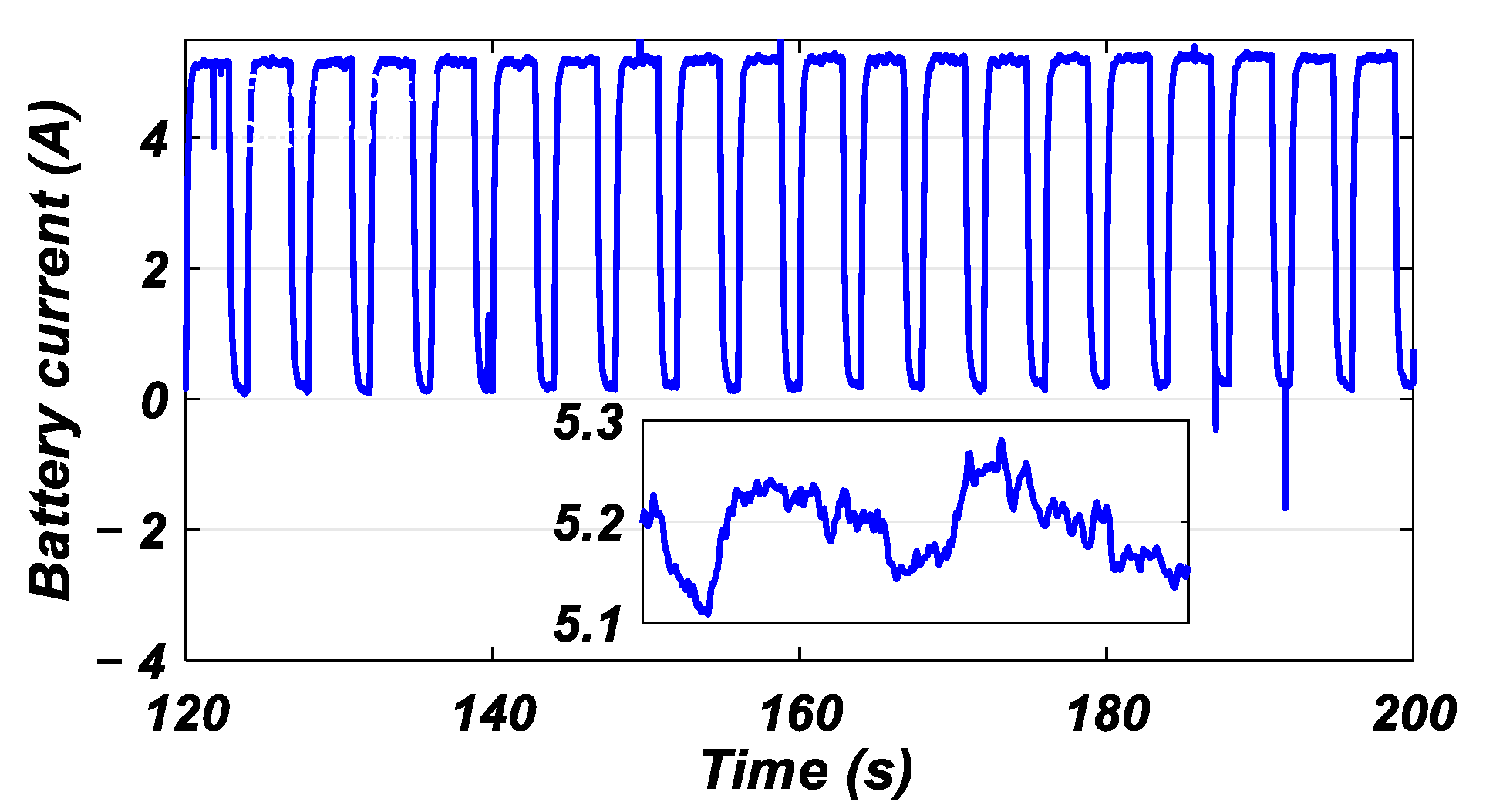
Figure 30 illustrates the behavior of the battery current during the charging test using the PCM applied in an open loop without regulation. Significant deviation between the reference and the measurement is seen: the reference is set at 5 A, but the actual current oscillates around 5.2 A (average error: +4%). These oscillations reflect the intrinsic instability of the open-loop PCM due to variations in the battery impedance during on–off phases and the converter response times due to the resonance in WPT systems. A control loop would be required to correct the static error with an average deviation of 0.2 A to reduce the oscillations around the reference value.
Following the experimental validation, we assessed the robustness of the MA-optimized PI controller in two distinct scenarios: (1) an ideal case, as shown in
Figure 26, where the coils are perfectly aligned with the air gap fixed at 120 mm, and (2) a compromised case, as shown in
Figure 31, with the air gap increased to 160 mm and misalignment Δx = Δy = 10 cm. The aim of these tests is to verify the system’s tolerance to variations in magnetic coupling, as are common in real-world wireless charging applications.
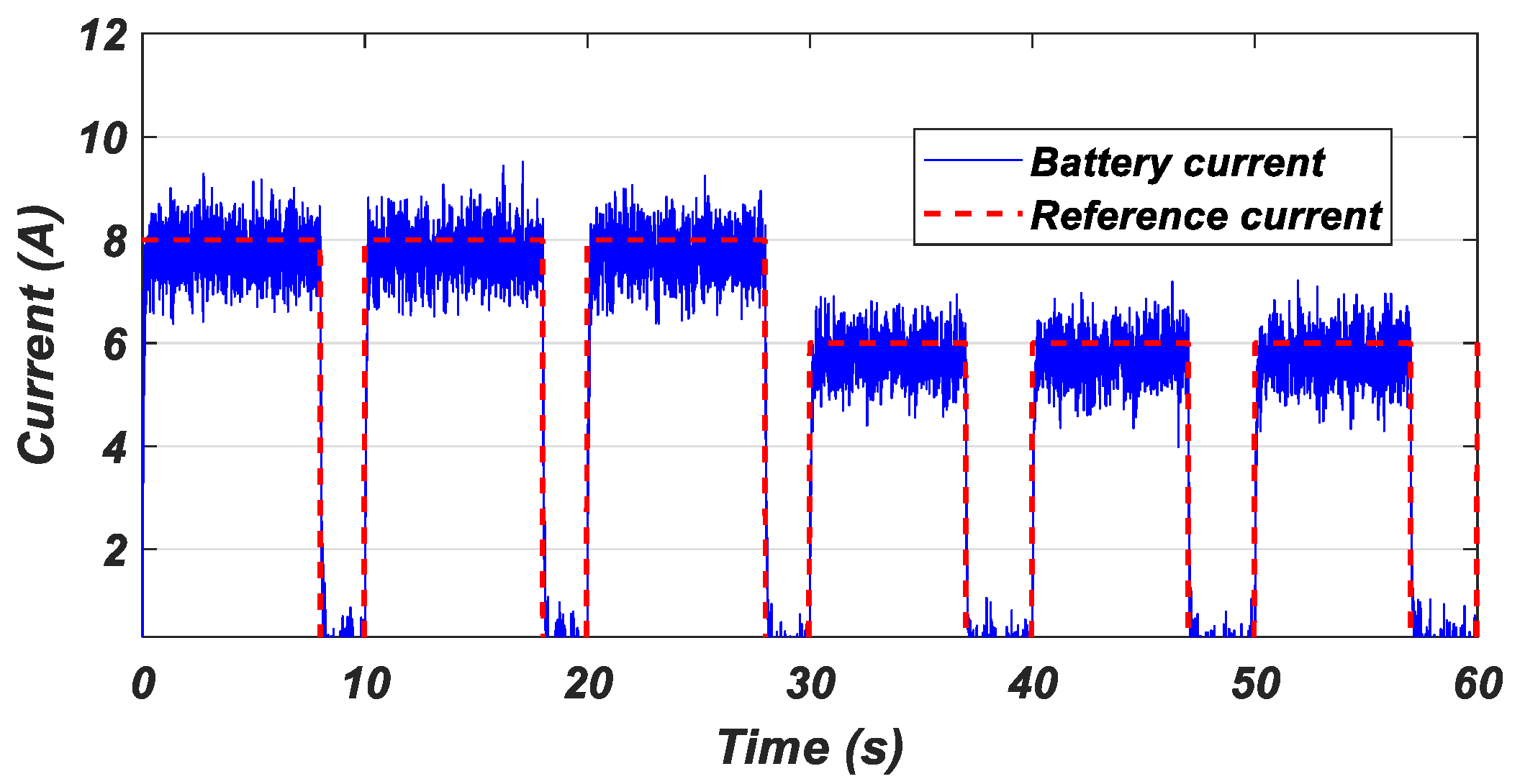
Figure 32 shows the results for case 1, where the charge current perfectly follows the reference without any overshoot, confirming the robustness and reliability of the proposed control method. This precision demonstrates the effectiveness of the MA-based PI controller in regulating the system despite dynamic variations in the magnetic coupling, guaranteeing exceptional stability under nominal conditions of a fixed air gap and perfect alignment. The absence of oscillations or tracking errors validates the controller’s ability to maintain the optimum performance with a response time <100 ms, essential for demanding industrial applications such as fast charging for EVs. These results underline the key advantage of our approach.
Figure 33 shows the performance of the control strategy in case 2, characterized by a coil misalignment of Δx = Δy = 10 cm and an air gap extended to 160 mm, conditions representative of the challenges encountered in real-life environments. Despite these disturbances, the MA-optimized controller maintains robust reference current tracking, with a maximum error of less than 5% and no major instabilities. These results highlight the system’s ability to adapt to variations in the magnetic coupling, preserving WPT in this degraded scenario even with low efficiency. This resilience confirms the applicability of the method to non-ideal wireless charging infrastructures, where positioning imperfections and increased distances are frequent.
In the following, this study will focus on a case of perfectly aligned coils with a normalized air gap of 120 mm, in accordance with the SAE J2954 standard. This configuration, essential for practical wireless charging applications in EVs, enables the system’s performance to be assessed under realistic conditions, particularly in terms of energy efficiency.
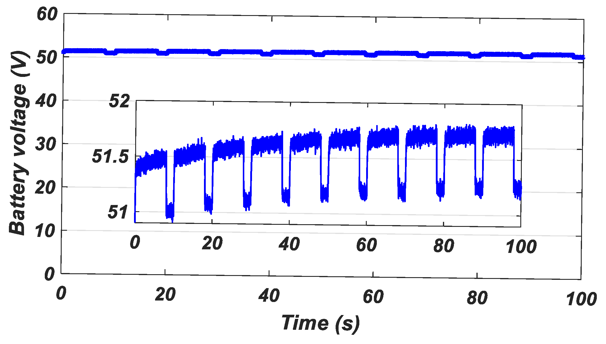
Figure 34 illustrates the evolution of the battery voltage when applying the hybrid MCM-PCM combination charging method. This graph shows no overvoltage as a result of dynamic current adaptation; high stability in the nominal voltage range; and minimal oscillations during transitions, confirming the effectiveness of the hybrid strategy in limiting electrochemical stress. These results validate the method’s ability to reconcile fast charging and battery preservation while respecting the constraints of the WPT system.
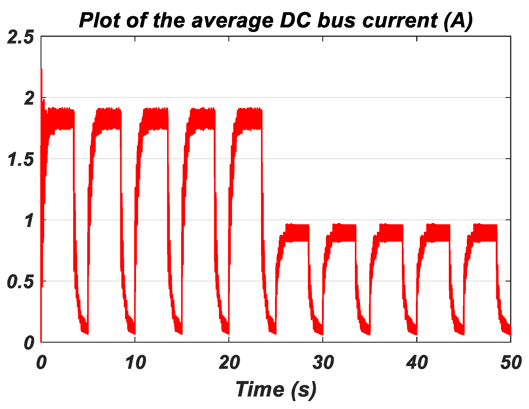
Figure 35 shows the average DC bus current as a function of time, highlighting its close correlation with variations in the battery current. It can be seen that the DC bus’s current closely follows the fluctuations in the battery charge current, reflecting the dynamics of the energy transfer between the WPT system and the battery. This match confirms the controller’s effectiveness in regulating the power in real time, particularly during transitions between different operating modes. The DC bus current’s peaks and troughs correspond to the battery current adjustments imposed by the MCM-PCM hybrid charging strategy, validating the system’s stability even under variable demand profiles.
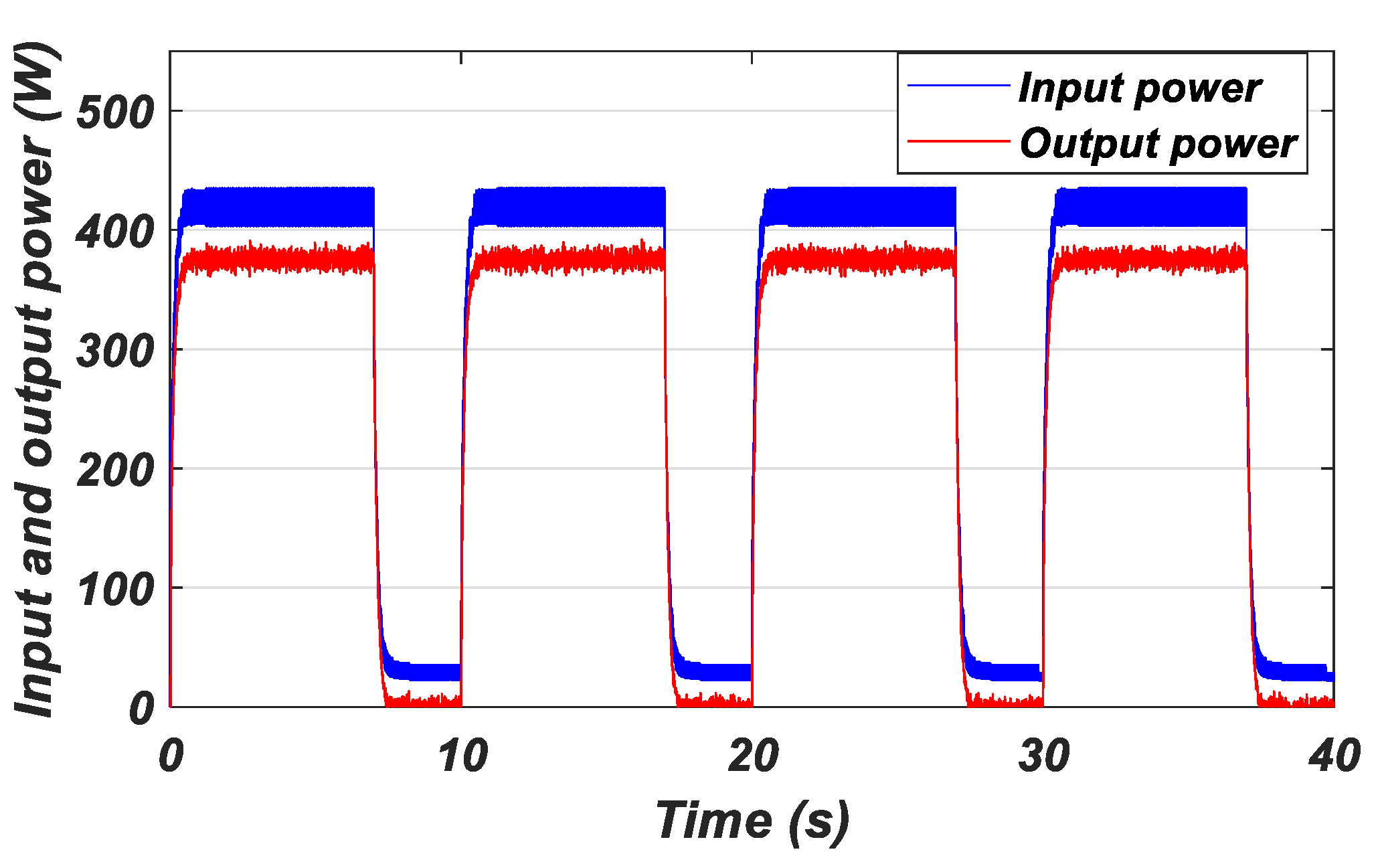
Figure 36 shows the input DC bus and output battery power profiles in the proposed hybrid charging system using a S-S compensation topology. The results show an average efficiency of 90%, confirming the suitability of this approach for high-power applications. The DC bus’s input power shows controlled variations linked to the transitions between MCM steps (dynamically adjusted constant currents) and PCM sequences (fixed-frequency pulses, e.g., 100 Hz, duty cycle = 70%). The peaks also correspond to changes in the charging mode. The battery’s output power remains stable thanks to the active regulation enabled by S-S compensation and the MA controller, which guarantees wireless energy transfer at a constant frequency of 85 kHz and minimizes the losses through optimized magnetic resonance with a high Q factor.
The results show that the MA controller maintains an efficiency of over 90% in the aligned case while preserving remarkable stability with less than 5% variation in the current in the misaligned case, thanks to its dynamic adaptation of the PI parameters. This robustness confirms its potential for WPT infrastructures in non-ideal conditions, such as public charging stations, where the vehicle positioning may vary. In addition to this, it should be noted that the superiority of the hybrid method over CC-CV is confirmed in terms of its speed and battery conservation.
7. Discussion
Our hybrid MCM and PCM approach, combined with a MA for adjusting the PI controller gains, fills an important gap in the literature. While most studies have focused either on fast charging or on preserving the battery’s SOH in wired chargers, the CC-CV mode of charging in WPT systems has always been the focus, our method integrates these two objectives synergistically. Accurate SOC estimation using neural networks enables dynamic adaptation of charging parameters such as the frequency, duty cycle, and amplitude, guaranteeing fast charging without compromising the battery’s longevity. This represents a major advance for WPT applications, where the balance between performance and durability remains a critical challenge. In
Table 3, we provide a comparative analysis of the different battery charging methods for WPT systems, highlighting the advantages of our proposed hybrid approach. Unlike conventional CC-CV methods, the PCM, and the MCM, which rely on fixed parameters or partial optimizations, our hybrid method introduces an ANN-based SOC estimator combined with a metaheuristic-optimized adaptive PI controller, enabling intelligent real-time adjustments. By incorporating tuning capabilities for the resonant frequency, our solution achieves full SAE J2954 compliance while optimizing both the charging efficiency and the battery’s lifespan. This AI-driven approach overcomes the limitations of the existing methods by dynamically adapting to system variations, making it the most advanced and battery-conscious charging strategy for modern WPT applications.
By optimizing the battery life, our proposed approach reduces the need for frequent replacement of the battery packs, thus limiting the mass production of batteries and its destructive impact on the environment, such as through the extraction of lithium, cobalt, etc. Widespread adoption of this technology could reduce the demand for critical resources, depending on the deployment scenarios. Furthermore, by coupling these chargers with renewable energies (solar, wind), we are paving the way for 100% green EVs, from energy generation to consumption. This integration promotes a circular economy, aligned with the United Nations’ Sustainable Development Goals (SDGs).
Beyond personal vehicles, our MCM-PCM hybrid system could revolutionize other areas of mobility and intelligent transport. It opens up promising prospects for autonomous transport, enabling fully automated wireless charging of smart buses and cars without the need for human intervention. Applications for drones and submarines are also conceivable, with submerged or aerial WPT terminals enabling autonomous, continuous recharging. Equally, this technology could greatly benefit people with reduced mobility by integrating wireless charging solutions into wheelchairs and urban infrastructures. To realize this vision, it will be essential to conduct pilot tests in collaboration with industrial partners while developing international standards specific to hybrid chargers. At the same time, the introduction of tax incentives could accelerate the adoption of these technologies, positioning intelligent WPT as a key element of tomorrow’s sustainable mobility.
The implementation of pulsed charging in WPT systems raises important considerations regarding electromagnetic interference (EMI) that warrant careful examination. While the current study focused on the charging methodology’s core performance metrics, the EMI characteristics of such systems represent a critical area for future investigation. Specifically, the spectral properties of pulsed power transfer under varying duty cycles, the potential for harmonic generation, and the compliance with international EMI standards (such as IEC 61000-3-11 [
52]) require systematic analysis. These factors are particularly relevant to automotive WPT applications where electromagnetic compatibility with the vehicle electronics and surrounding environments is paramount. Future work should address these EMI considerations through both simulations and experimental characterization to fully validate this technology’s suitability for real-world deployment.
Despite the fact that the proposed method promises improvements in terms of the optimal charging modes for fast charging and battery protection, limitations still persist and are recommendations for future investigations:
A lack of standardization, with no established protocol for the transition criteria between the MCM and the PCM;
Determination of the optimum pulse parameters (frequency, duty cycle) adapted to all battery chemistries;
Validation under real-life conditions is limited, as laboratory tests do not consider the variability in power grids and the impact of battery aging on the long-term efficiency.
These limitations provide research gaps and the motivation to contribute to healthy and efficient charging of batteries using WPT technology.


 ,
, 


