
PMSM Position Sensorless Control Based on Improved Second-Order SOIFO


Abstract
1. Introduction
2. Analysis of Proposed Sensorless PMSM Control
2.1. PMSM Mathematical Model
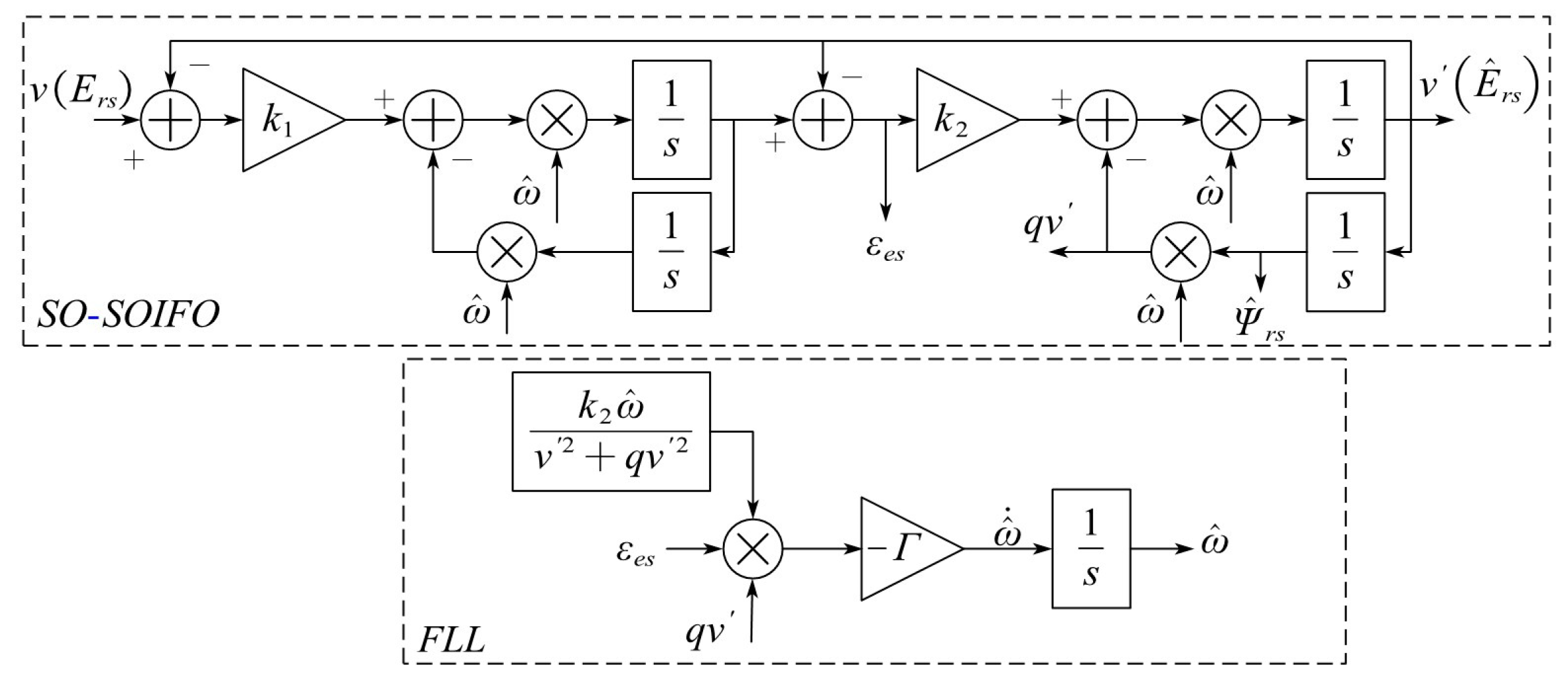
2.2. Second-Order SOIFO
2.3. Improved Second-Order SOIFO
2.3.1. Analysis of FLL
2.3.2. Analysis of DFLL
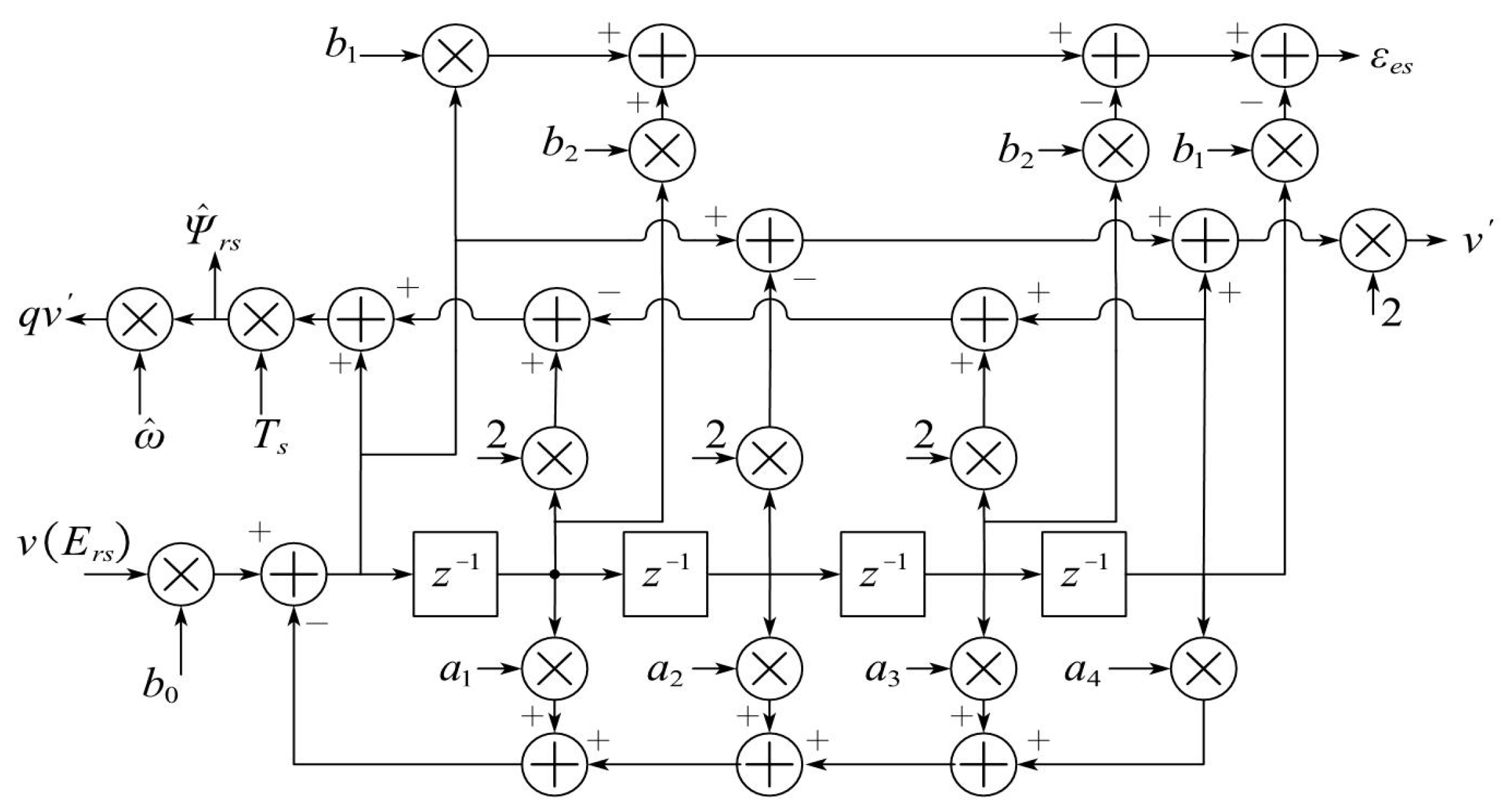
2.4. Discretization Method
3. Simulation Analysis
3.1. Simulation Parameters
3.2. Simulation Result
3.2.1. Simulation of Motor Operation Under Sudden Speed Variations
3.2.2. Simulation of Motor Operation Under Load Variations
3.2.3. Simulation of Motor Operation over a Wide Speed Range
3.2.4. Simulation of the Motor Operation with Parameter Deviation or DC Bias
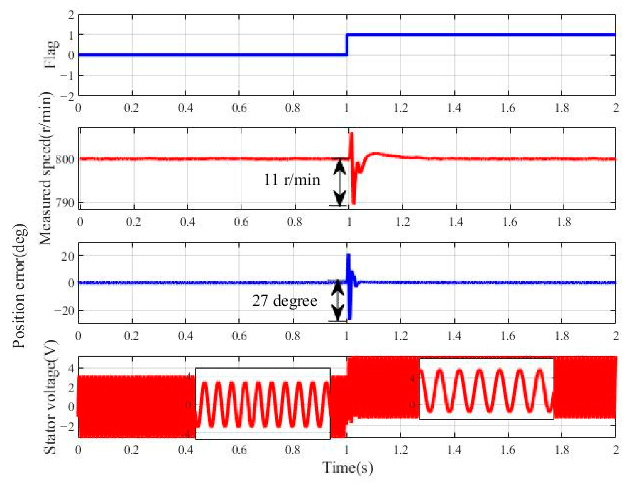
- Simulation of the motor operation with a voltage DC biasUnder actual experimental conditions, the acquired voltage signals may contain a DC bias. To evaluate the robustness of the proposed method, the speed command is set to 800 r/min with no load and a 2 V DC offset is imposed on the stator voltage at 1 s. In the Figure 9, represents 0 V, and represents +2 V. As shown in Figure 9, after the stator voltage increases, the maximum speed drop is approximately 11 r/min, and the maximum position error reaches around 27°. The system then quickly recovers to a steady state, demonstrating that the proposed scheme has excellent performance in suppressing DC voltage bias.
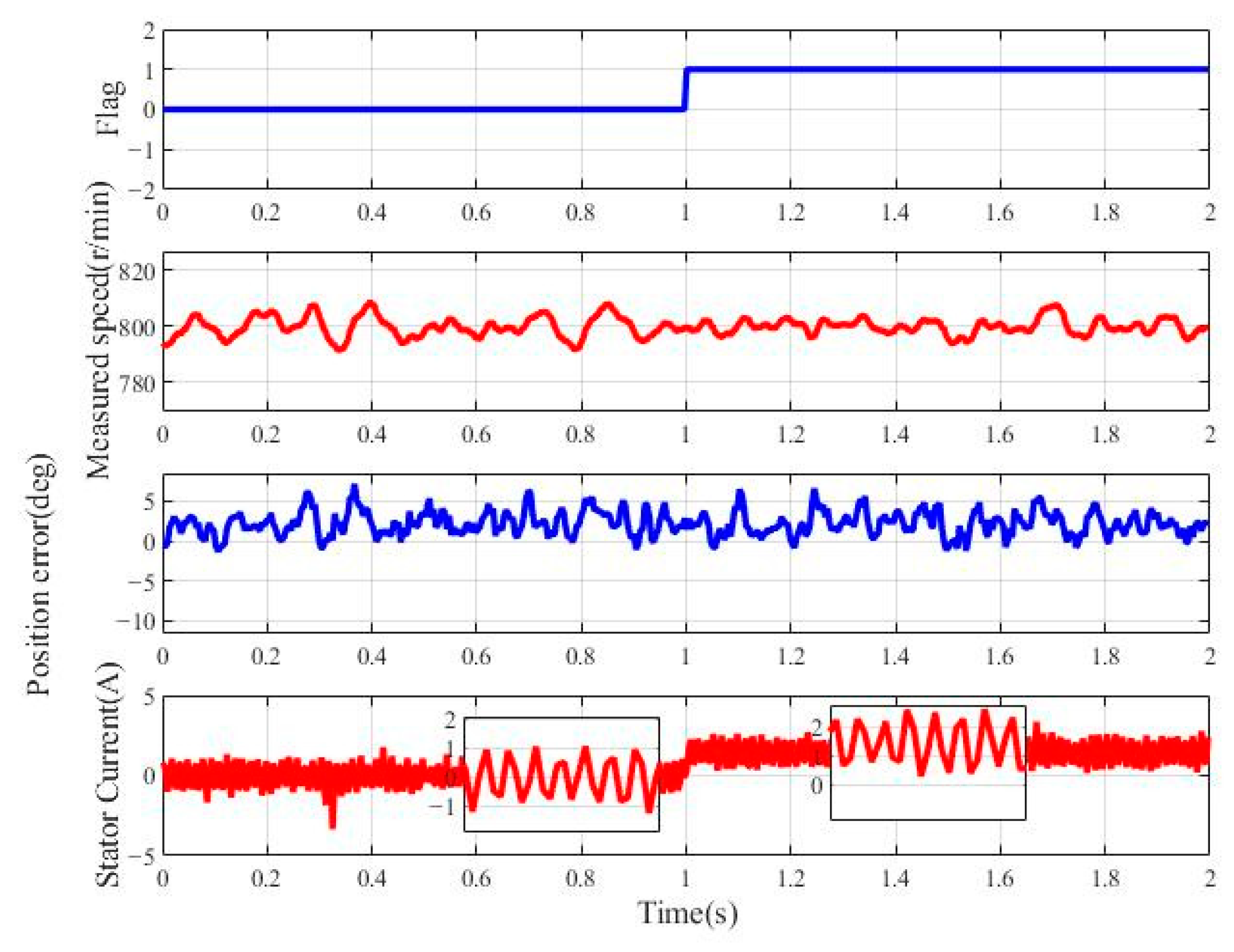
- Simulation of the motor operation with a current DC biasUnder actual experimental conditions, the acquired current signals may contain a DC bias. To assess the robustness of the proposed method, the speed command is set to 800 r/min with no load and a 1.5 A DC bias is imposed on the stator current at 1 s. In Figure 10, represents 0 A, and represents +1.5 A. As shown in Figure 10, after imposing the DC bias on the stator current , the maximum measured speed drop is approximately 3 r/min, and the maximum position error is around 6°. The system then quickly recovers to a steady state, demonstrating that the proposed scheme has excellent performance in suppressing current DC bias.
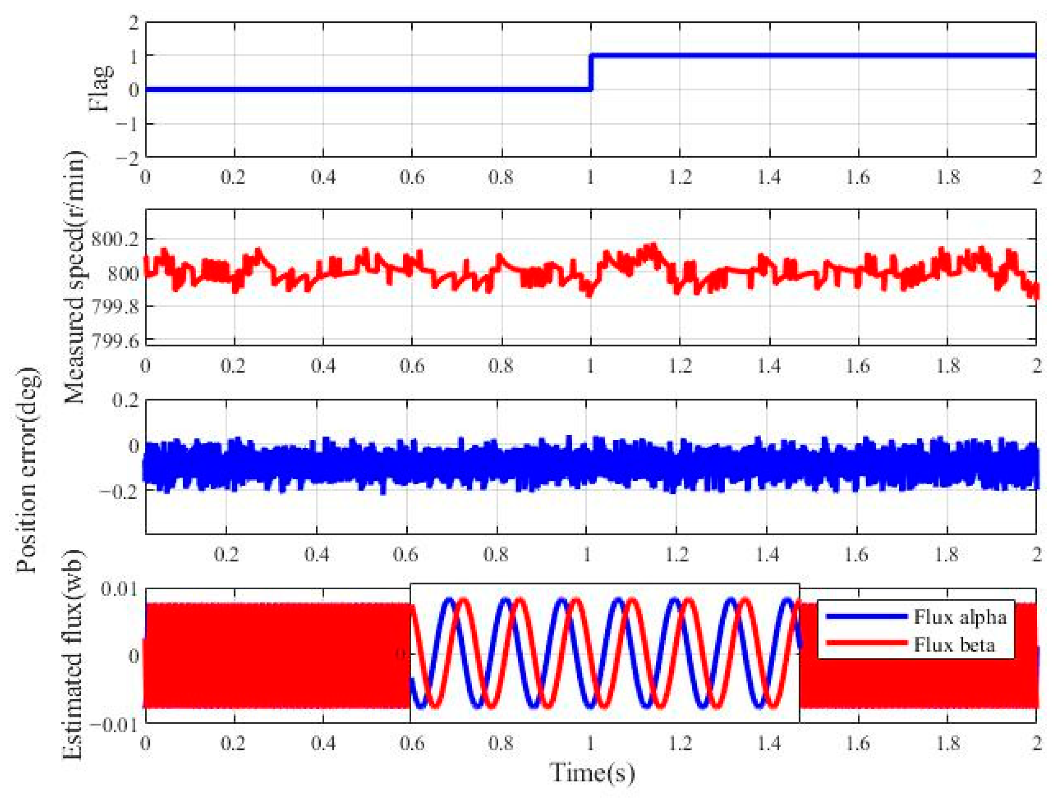
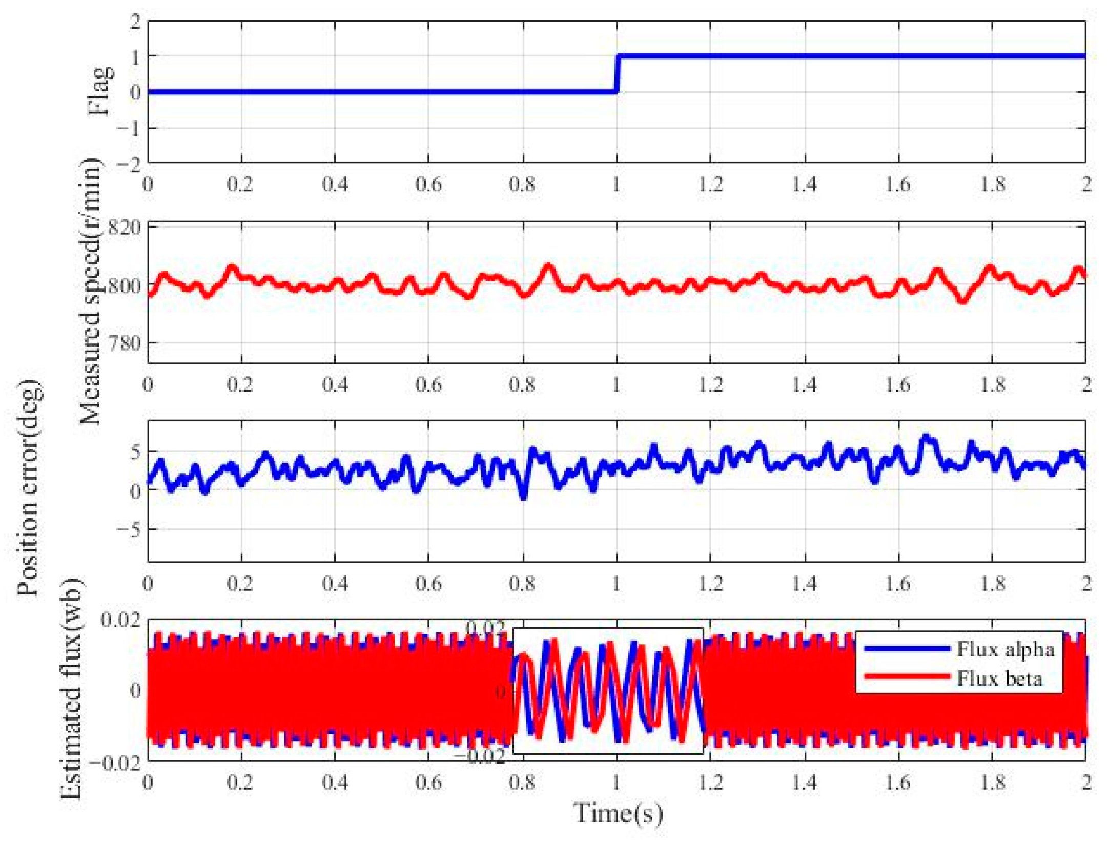
- Simulation of the motor operation with stator resistance deviationUnder actual experimental conditions, the resistance value used in the control algorithm may have measurement errors. To evaluate the robustness of the proposed method, the speed command is set to 800 r/min with no load and the stator resistance is increased to 1.5 times its original value at 1 s. In Figure 11, represents , and represents . As shown in Figure 11, after the stator resistance is increased by 50%, the estimated rotor flux linkage remains almost unchanged, the actual motor speed remains unaffected, and the position error remains stable. Therefore, the proposed scheme has excellent performance in suppressing the resistance deviation.
- Simulation of the motor operation with stator inductance deviationUnder actual experimental conditions, the stator inductance used in the control algorithm may have measurement errors. To evaluate the robustness of the proposed method, the speed command is set to 800 r/min with no load, and the stator inductance is increased to 1.5 times its original value at 1 s. In Figure 12, represents , and represents . As shown in Figure 12, after the stator inductance is increased by 50%, the estimated flux linkage remains almost unchanged, the actual motor speed is not affected, and the position error remains the same. Therefore, the proposed scheme has excellent performance in suppressing inductance measurement errors.
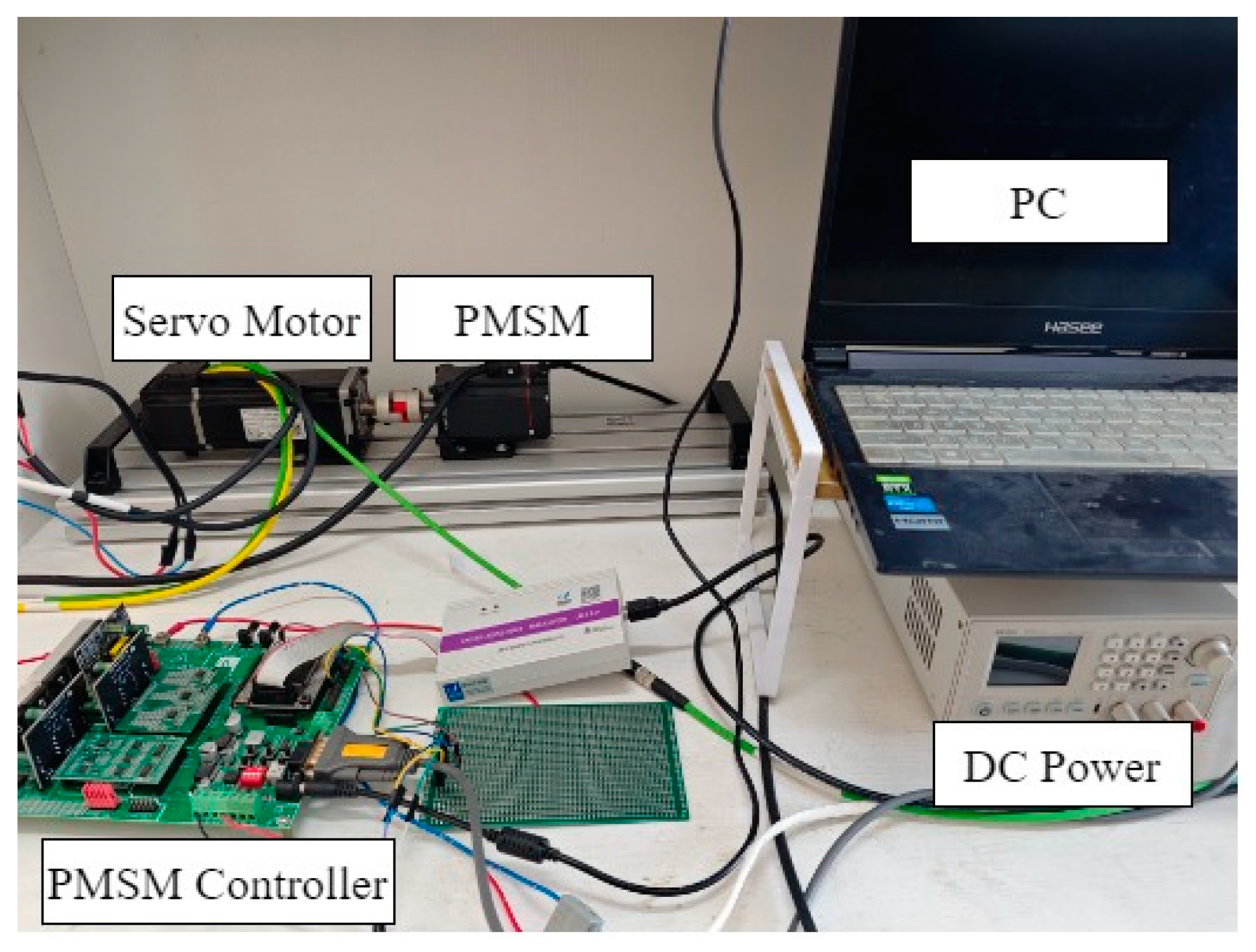
4. Experimental Analysis
4.1. Experiment Parameters
4.2. Experimental Results
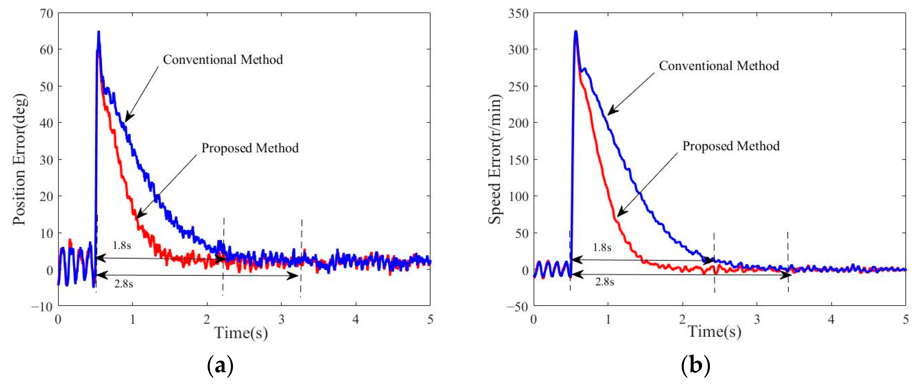
4.2.1. Experimental Verification of Motor Operation Under Sudden Speed Variations
4.2.2. Experimental Verification of Motor Operation Under Load Variations
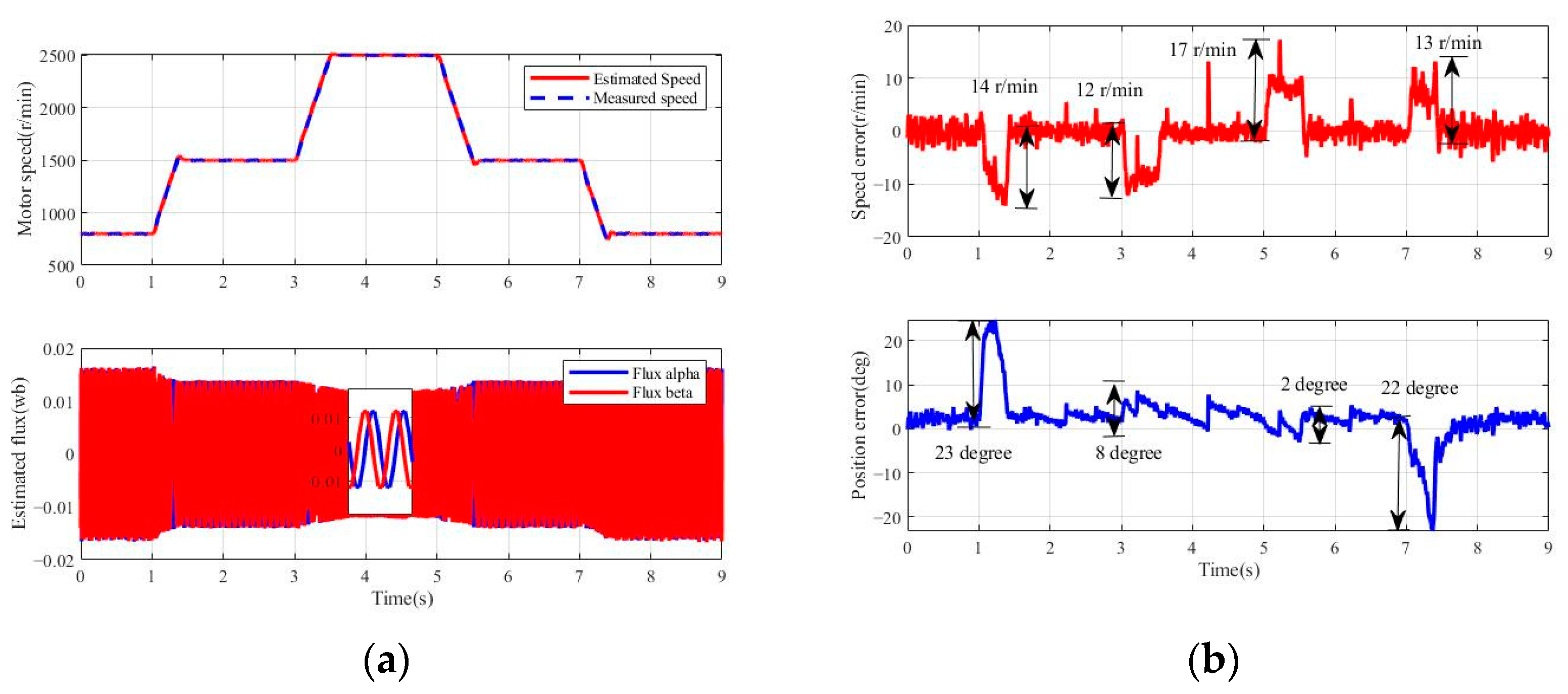
4.2.3. Experimental Verification of Motor Operation over a Wide Speed Range
4.2.4. Experiment of the Motor Operation with Parameter Deviation
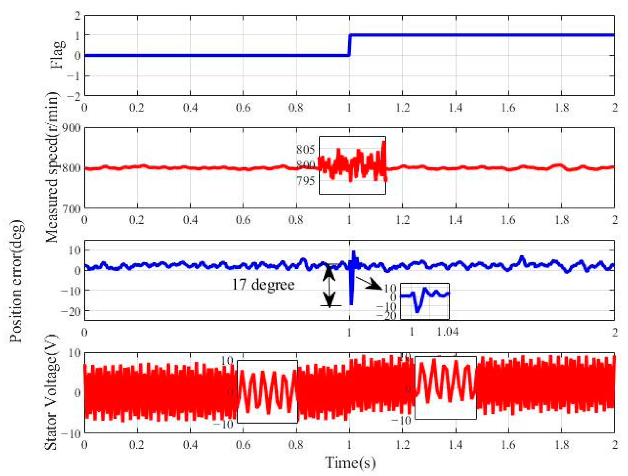
- Experiment of the motor operation with a voltage DC biasUnder actual experimental conditions, the acquired voltage signals may contain a DC bias. Therefore, the speed command is set to 800 r/min with no load and a 2 V DC offset is imposed on the stator voltage at 1s. In Figure 17, represents 0 V, and represents +2 V. As shown in Figure 17, after the stator voltage increases, the actual motor speed is not affected, and the maximum position error is around 17°. The system then quickly recovers to a steady state, demonstrating that the proposed scheme has excellent performance in suppressing DC voltage bias.
- Experiment of the motor operation with a current DC biasUnder actual experimental conditions, the acquired current signals may contain a DC bias. Therefore, the speed command is set to 800 r/min with no load and a 1.5 A DC bias is imposed on the stator current at 1s. In Figure 18, represents 0 A and represents +1.5 A. As shown in Figure 18, after imposing the DC bias on the stator current , the actual motor speed is not affected, and the position error remains the same. Therefore, the proposed scheme has excellent performance in suppressing the current DC bias.
- Experiment of the motor operation with stator resistance deviationUnder actual experimental conditions, the resistance value used in the control algorithm may have measurement errors. Therefore, the speed command is set to 800 r/min with no load and the stator resistance is increased to 1.5 times its original value at 1 s. In Figure 19, represents , and represents . As shown in Figure 19, after the stator resistance is increased by 50%, the estimated rotor flux linkage remains almost unchanged, the actual motor speed is not affected, and the position error remains the same. Therefore, the proposed scheme has excellent performance in suppressing the resistance deviation.
- Experiment of the motor operation with stator inductance deviationUnder actual experimental conditions, the stator inductance used in the control algorithm may have measurement errors. Therefore, the speed command is set to 800 r/min with no load, and the stator inductance is increased to 1.5 times its original value at 1 s. In Figure 20, represents , and represents . As shown in Figure 20, after the stator inductance is increased by 50%, the estimated flux linkage remains almost unchanged, the actual motor speed is not affected, and the position error remains the same. Therefore, the proposed scheme has excellent performance in suppressing inductance measurement errors.
5. Conclusions
Author Contributions
Funding
Data Availability Statement
Conflicts of Interest
References
- Xing, J.; Zhang, J.; Zhuang, X.; Xu, Y. Online Inductance Identification of Permanent Magnet Synchronous Motors Independent of Rotor Position Information. World Electr. Veh. J. 2024, 15, 35. [Google Scholar] [CrossRef]
- Ferdiansyah, I.; Hanamoto, T. FPGA-Based High-Frequency Voltage Injection Position Sensorless Control with Novel Rotor Posit-ion Estimation Extraction for Permanent Magnet Synchronous Motor. World Electr. Veh. J. 2024, 15, 506. [Google Scholar] [CrossRef]
- Liang, D.; Li, J.; Qu, R.; Kong, W. Adaptive Second-Order Sliding-Mode Observer for PMSM Position Sensorless Control Considering VSI Nonlinearity. IEEE Trans. Power Electron. 2017, 33, 8994–9004. [Google Scholar] [CrossRef]
- Xu, Y.; Lin, C.; Xing, J. Transient response characteristics improvement of permanent magnet synchronous motor based on enhanced linear active disturbance rejection sensorless control. IEEE Trans. Power Electron. 2023, 38, 4378–4390. [Google Scholar] [CrossRef]
- Qu, L.; Qiao, W.; Qu, L. An enhanced linear active disturbance rejection rotor position sensorless control for perma-nent magnet synchronous motors. IEEE Trans. Power Electron. 2020, 35, 6175–6184. [Google Scholar] [CrossRef]
- Rafaq, M.S.; Mwasilu, F.; Kim, J.; Choi, H.H.; Jung, J.-W. Online parameter identification for model-based sensorless control of interior permanent magnet synchronous machine. IEEE Trans. Power Electron. 2017, 32, 4631–4643. [Google Scholar] [CrossRef]
- Du, B.; Wu, S.; Han, S.; Cui, S. Application of linear active disturbance rejection controller for sensorless control of internal permanentmagnet synchronous motor. IEEE Trans. Ind. Electron. 2016, 63, 3019–3027. [Google Scholar] [CrossRef]
- Liu, J.; Zhang, Y. Performance improvement of nonlinear flux observer for sensorless control of PMSM. IEEE Trans. Ind. Electron. 2023, 70, 12014–12023. [Google Scholar] [CrossRef]
- Lin, Q.; Liu, L.; Liang, D. Hybrid active flux observer to suppress position estimation error for sensorless IPMSM drives. IEEE Trans. Power Electron. 2023, 38, 872–886. [Google Scholar] [CrossRef]
- Woldegiorgis, A.T.; Ge, X.; Wang, H.; Zuo, Y. An active flux estimation in the estimated reference frame for sensorless control of IPMSM. IEEE Trans. Ind. Electron. 2022, 37, 9047–9060. [Google Scholar] [CrossRef]
- Ye, S.; Yao, X. A modified flux sliding-mode observer for the sensorless control of PMSMs with online stator resistance and inductance estimation. IEEE Trans. Power Electron. 2020, 35, 8652–8662. [Google Scholar] [CrossRef]
- Stojic, D.; Milinkovic, M.; Veinovic, S.; Klasnic, I. Improved stator flux estimator for speed sensorless induction motor drives. IEEE Trans. Power Electron. 2015, 30, 2363–2371. [Google Scholar] [CrossRef]
- Wang, Y.; Deng, Z. An integration algorithm for stator flux estimation of a direct-torque-controlled electrical excitation flux-switching generator. IEEE Trans. Energy Convers. 2012, 27, 411–420. [Google Scholar] [CrossRef]
- Jiang, Y.; Xu, W.; Mu, C.; Zhu, J.; Dian, R. An improved third-order generalized integral flux observer for sensorless drive of PMSMs. IEEE Trans. Ind. Electron. 2019, 66, 9149–9160. [Google Scholar] [CrossRef]
- Xin, Z.; Zhao, R.; Blaabjerg, F.; Zhang, L.; Loh, P.C. An improved flux observer for field-oriented control of induction motors based on dual second-order generalized integrator frequency-locked loop. IEEE J. Emerg. Sel. Top. Power Electron. 2017, 5, 513–525. [Google Scholar] [CrossRef]
- Xu, W.; Jiang, Y.; Mu, C.; Blaabjerg, F. Improved Nonlinear Flux Observer-Based Second-Order SOIFO for PMSM Sensorless Control. IEEE Trans. Power Electron. 2019, 34, 565–579. [Google Scholar] [CrossRef]
- Ciobotaru, M.; Teodorescu, R.; Blaabjerg, F. A New Single-Phase PLL Structure Based on Second Order Generalized Integrator. In Proceedings of the 2006 37th IEEE Power Electronics Specialists Conference (PESC), Jeju, Republic of Korea, 18–22 June 2006. [Google Scholar] [CrossRef]


| Parameters | Value |
|---|---|
| Rated voltage | 48 V |
| Rated speed | 3000 r/min |
| Rated current | 11 A |
| Rated torque | 1.27 N·m |
| Rotational inertia | 5.8 × 10⁻⁵ kg·m2 |
| Stator resistance | 0.48 Ω |
| Stator inductance | 0.56 mH |
| Pole-pair number | 5 |
| Flux linkage of permanent magnet | 0.0142 Wb |
Disclaimer/Publisher’s Note: The statements, opinions and data contained in all publications are solely those of the individual author(s) and contributor(s) and not of MDPI and/or the editor(s). MDPI and/or the editor(s) disclaim responsibility for any injury to people or property resulting from any ideas, methods, instructions or products referred to in the content. |
© 2025 by the authors. Published by MDPI on behalf of the World Electric Vehicle Association. Licensee MDPI, Basel, Switzerland. This article is an open access article distributed under the terms and conditions of the Creative Commons Attribution (CC BY) license (https://creativecommons.org/licenses/by/4.0/).
Share and Cite
Song, G.; Ni, H.; Wang, W.; Yan, W. PMSM Position Sensorless Control Based on Improved Second-Order SOIFO. World Electr. Veh. J. 2025, 16, 182. https://doi.org/10.3390/wevj16030182
Song G, Ni H, Wang W, Yan W. PMSM Position Sensorless Control Based on Improved Second-Order SOIFO. World Electric Vehicle Journal. 2025; 16(3):182. https://doi.org/10.3390/wevj16030182
Chicago/Turabian StyleSong, Ge, Hongyu Ni, Wenyuan Wang, and Wenxu Yan. 2025. "PMSM Position Sensorless Control Based on Improved Second-Order SOIFO" World Electric Vehicle Journal 16, no. 3: 182. https://doi.org/10.3390/wevj16030182
APA StyleSong, G., Ni, H., Wang, W., & Yan, W. (2025). PMSM Position Sensorless Control Based on Improved Second-Order SOIFO. World Electric Vehicle Journal, 16(3), 182. https://doi.org/10.3390/wevj16030182