Article

Anti-Lock Braking System Performance Optimization Based on Fitted-Curve Road-Surface Recognition and Sliding-Mode Variable-Structure Control

1
Department of Vehicle Engineering, School of Automobile and Traffic Engineering, Jiangsu University, Zhenjiang 212013, China
2
Department of Vehicle Engineering, Automotive Engineering Research Institute, Jiangsu University, Zhenjiang 212013, China
3
Jiangsu Chaoli Electric Manufacture Co., Ltd., No. 1, Xingyuan East Road, Industrial Zone, Fangxian Town, Danyang 212321, China
*
Author to whom correspondence should be addressed.
World Electr. Veh. J. 2025, 16(3), 156; https://doi.org/10.3390/wevj16030156
Submission received: 15 January 2025 / Revised: 4 March 2025 / Accepted: 5 March 2025 / Published: 6 March 2025

Abstract

:
This paper conducts an in-depth study on anti-lock braking technology in electronic hydraulic braking systems, focusing on a road-surface recognition algorithm based on fitted curves and a slip-rate control method based on sliding-mode variable structure. Firstly, a road-surface recognition algorithm using fitted curves is proposed, which extracts characteristic information by fitting the μ-λ curve, achieving the accurate identification of different road-surface conditions and providing optimal slip rates for subsequent braking control. Secondly, a slip-rate control strategy based on sliding-mode variable structure is designed to achieve optimal slip-rate control during vehicle braking, ensuring braking stability and safety under varying road conditions. Through theoretical analysis and simulation experiments, the results show that the proposed road-surface recognition algorithm can effectively identify various typical road surfaces (such as dry, wet, and icy/snowy surfaces) with high accuracy. The sliding-mode variable-structure control strategy can achieve good slip-rate control under different road conditions, effectively improving vehicle braking performance. This study provides an efficient and reliable technical solution for anti-lock braking control in electronic hydraulic braking systems, with significant theoretical and practical implications for enhancing vehicle braking safety.

1. Introduction

In recent years, with the flourishing development of the automotive industry, vehicle driving safety has become one of the core issues of concern in the industry. As a key component in ensuring vehicle driving safety, the improvement of braking system performance plays a crucial role in preventing traffic accidents [1]. The electronic hydraulic brake (EHB) system, as an advanced braking system, has been widely applied in modern vehicles [2].
The EHB system achieves rapid and accurate pressure build-up through motor-driven active pressure control, decoupling the brake pedal from the master cylinder, and can quickly and accurately provide the braking pressure desired by the driver [3]. This feature provides the foundation for implementing vehicle anti-lock braking, body stability, and other functions, while meeting the requirements for vehicle intelligence and electrification. Due to its low complexity and high integration, the EHB system has become the mainstream trend in current vehicle-braking-system development [3,4].
ABS is an important component of the EHB system. It can prevent wheel lock-up during braking, maintaining adhesion between the wheels and the road surface, thereby ensuring vehicle stability and controllability [5]. Traditional ABS control algorithms, such as logic threshold control, mainly rely on extensive experimental data to tune the controller. However, this approach has limited adaptability in complex road conditions [6].
Currently, control methods based on optimal slip rate mainly include PID control, sliding-mode variable-structure control, optimal control, and neural network control [7]. Among these, sliding-mode variable-structure control has shown great potential in ABS control due to its strong robustness against system parameter variations and external disturbances [8].
ABS based on classical PID control [9,10,11,12] has significant limitations. Its control principle is based on linear system theory and is only applicable to linear feedback systems. In the actual vehicle braking process, the dynamics of the vehicle will change nonlinearly with the driving conditions, road-surface conditions and changes in vehicle load. For example, under different road conditions, the friction between the tires and the road surface shows a complex nonlinear relationship, which makes it difficult for the classical PID control to adapt to these nonlinear changes, and the optimal control of the braking system cannot be achieved.
In order to improve the performance of the braking system, it is crucial to make full use of the adhesion between the tires and the road surface. The adhesion between the tires and the road surface is an important factor in determining the braking effect of the vehicle, and only when the adhesion between the tires and the road surface is fully utilized can the vehicle achieve the shortest braking distance and the best braking stability. Thus, the method of tracking the optimal slip rate [13,14,15] came into being. This method aims to accurately confirm the optimal slip rate of the vehicle under different road conditions through various technical means. The optimal slip rate is the slip rate at which the tires are at their best grip. To realize the tracking of the optimal slip rate, researchers have proposed a variety of slip-rate control methods. These methods are usually based on modern control theories, such as adaptive control, sliding-mode variable-structure control, etc., which can dynamically adjust the braking pressure according to the real-time state of the vehicle and road conditions, so as to keep the wheel slip rate within the optimal range. The advantage of these methods is that they have a certain degree of anti-interference ability, and can overcome to a certain extent the influence of road-surface unevenness, vehicle load changes and other disturbing factors on braking performance. However, when facing extreme weather conditions, these methods still reveal certain defects. For example, under severe weather such as heavy rain, heavy snow, or ice, the friction coefficient of the road surface will drop sharply, and the change rule becomes more complicated. At this time, the traditional slip-rate control method may not be able to accurately track the optimal slip rate, leading to a decline in braking performance, and even the risk of vehicle loss of control.
In order to solve this problem, some research [16,17,18] is committed to obtaining the optimal slip rate in real time by detecting the road-surface condition. This method [19,20,21,22,23] usually monitors and analyses the road-surface condition in real time with the help of various sensors, such as radar, camera, and laser sensors. Based on the detected road-surface information, such as road-surface roughness, humidity, degree of ice and snow cover, etc., the optimal slip rate under the current road-surface conditions is calculated by combining with the vehicle dynamics model. However, this method, based on road-surface detection, also has certain limitations. Firstly, the detection accuracy and clarity of sensors such as radar can be affected by adverse weather conditions. In heavy rain, dense fog, and other weather, the radar signal is easily interfered with, resulting in a decrease in detection accuracy and the inability to accurately obtain road-surface information. Second, the additional sensors not only increase the cost and complexity of the system, but also may cause problems such as sensor failure or data fusion errors, affecting the reliability and stability of the system.
A fitted curve is a set of data points processed through certain mathematical methods to obtain a curve that reflects the trend of the distribution of those data points as accurately as possible. The principle is to find a function expression based on the statistical properties of the data and a mathematical model that makes the value of the function at a given data point as close as possible to the actual data. In the study of tire characteristics of vehicles, the relationship curves of longitudinal force, transverse force, adhesion coefficient, etc., of tires and slip rate can be obtained by fitting the experimental data, which provides an important basis for the analysis of vehicle dynamics and the design of control system. For example, in the study of tire adhesion characteristics under different road conditions, through the fitting of the adhesion coefficient—the slip rate curve—you can clearly see how the tire adhesion coefficient changes with the slip rate in dry, wet, icy and other different road-surface conditions, so as to provide a reference for the adjustment of the parameters of the vehicle braking and drive-control system. The slip rate is the degree of relative movement that occurs between the tire and the ground when the tire exerts traction or braking force. The goal of slip-rate control is to keep the wheels within a suitable slip-rate range during braking in order to obtain optimum tire–ground adhesion. During braking, if the wheels are locked (slip rate of 100%), the friction between the tire and the ground will change from a large dynamic friction to a small sliding friction, the braking distance will be significantly increased, and the vehicle will easily lose directional control.
This paper aims to conduct an in-depth study on the application of road-surface recognition algorithms based on fitted curves and slip-rate control based on sliding-mode variable structure in EHB system anti-lock braking. Through theoretical analysis and simulation research, we explore how to combine these two technologies to achieve effective control of vehicle anti-lock braking under different road conditions, providing new theoretical and technical support for improving vehicle braking safety [24].
The main innovations and contributions of this study include:
(1) Proposing a road-surface recognition algorithm based on fitted curves, capable of accurately identifying multiple road conditions;
(2) Designing a slip-rate control strategy based on sliding-mode variable structure, achieving precise control of vehicle slip rate;
(3) Verifying the effectiveness and robustness of the proposed method under different road conditions through simulation.

2. Methodology

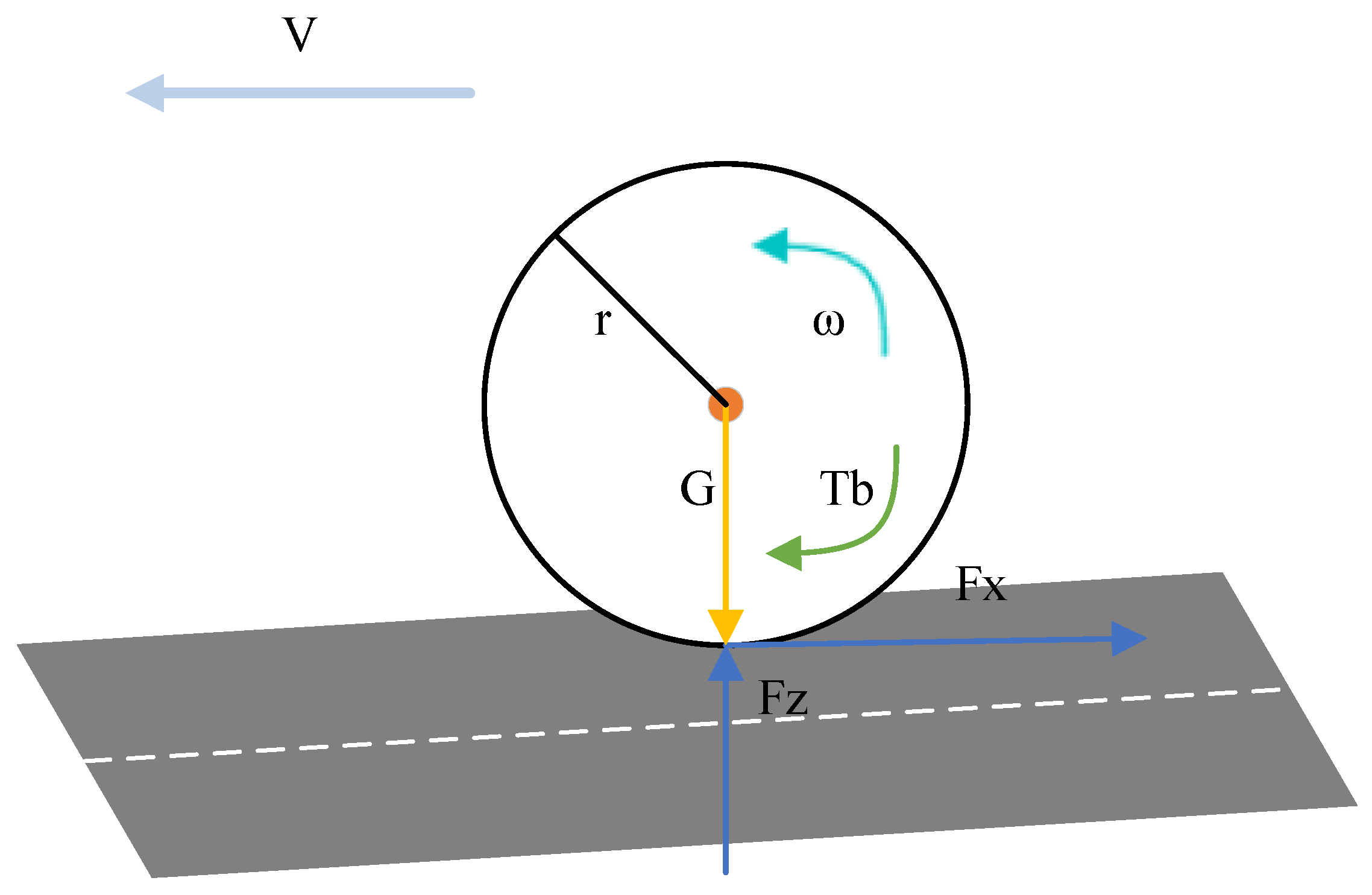
2.1. Single-Wheel Braking Model

Vehicle Dynamics Modeling [25]: This paper adopts a single-wheel model [26]. According to the needs of the study, the single-wheel model can be easily extended and improved by adding more physical factors and constraints to make it closer to the operation of real vehicles. As shown in Figure 1, where T b is the braking torque on a single wheel, F Z is the vertical force transmitted from the vehicle to the ground through the tire, F x is the longitudinal braking force on the tire from the ground during vehicle braking, G is the gravitational force on the vehicle, ω is the angular velocity of the wheel, r is the wheel radius (not considering the inner and outer diameters of the tire here), V is the vehicle speed, and m is the mass on each wheel.
To study the anti-lock braking problem, the following assumptions are made to simplify the issue:
Assumption 1: This paper does not consider tire deformation or the standing-wave phenomenon caused by high-speed driving.
Assumption 2: The road in this paper does not consider slopes or curves.
Assumption 3: The vehicle weight is evenly distributed on the left and right tires.
Assumption 4: Air resistance and rolling resistance are ignored.
The vehicle dynamics model is established as follows:
F x = m V ˙
The tire rotational dynamics are established as follows:
ω i ˙ I = r T b
where I is the moment of inertia of the tire. The controlled wheel speed can be expressed as ω i , where i = front left wheel (FL), front right wheel (FR), rear left wheel (RL), and rear right wheel (RR).

2.2. Slip-Rate Model

During vehicle travel, the road conditions encountered by the left and right tires may differ, leading to different slip rates during braking. Since the electronic hydraulic braking system can control different brake actuators on the left and right sides simultaneously through switching valves, when the slip rates of the left and right tires differ, the yaw moment generated by braking will be applied to the vehicle body and affect the vehicle’s trajectory. Therefore, the tire with the smaller slip rate on the same side is selected as the controlled object.
During emergency braking, as the braking intensity increases and the road adhesion coefficient decreases, insufficient braking force is provided, causing the wheels to transition from rolling to sliding. The degree of wheel slip is represented by the slip rate [27], which is calculated as:
λ = V ω i r V
where λ is the wheel slip rate.

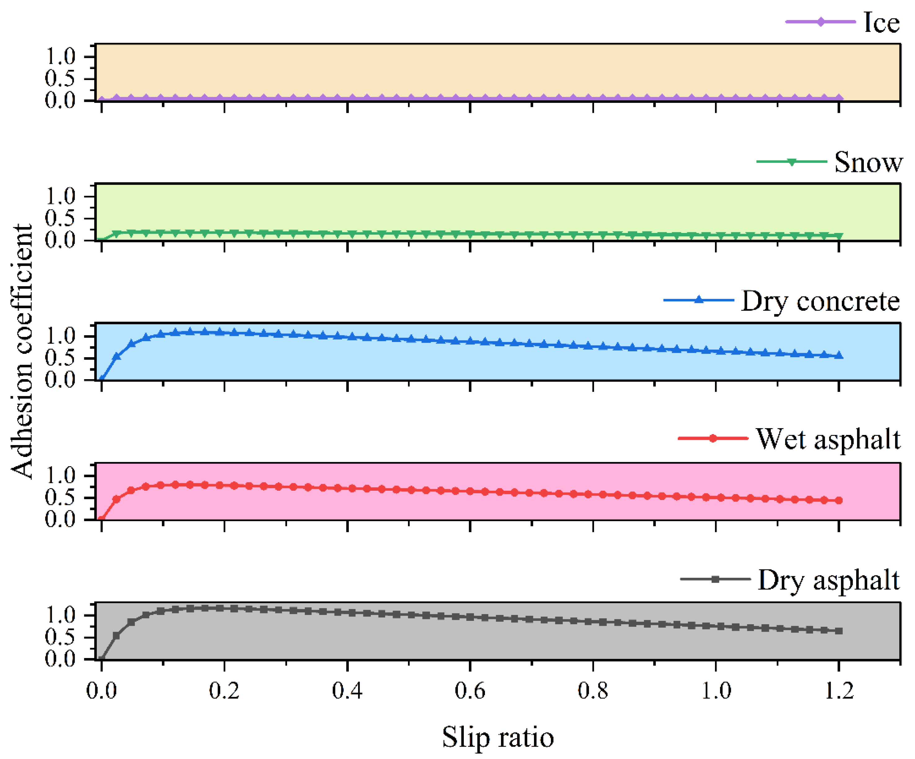
2.3. Burckhardt Tire Model

This paper adopts the Burckhardt tire model [28], which is a semi-empirical tire model that combines linear and exponential functions to fit tire mechanical performance data. The model is capable of providing a relatively accurate description of the friction characteristics between tires and road surfaces by means of specific formulas and parameters. It provides relatively reliable simulation results under different road conditions such as dry asphalt, wet asphalt, dry cobbles, wet cobbles, snow and ice. The small number of parameters used to describe the longitudinal and transverse tire interactions reduces the complexity and computational cost of the model, while the variation in its parameters can be physically characterized, retaining a semi-empirical nature.
The longitudinal adhesion-coefficient relationship between the tire and road surface is derived from this model as:
μ λ = c 1 1 e c 2 λ c 3 λ
where c 1 , c 2 , and c 3 are fitting parameters related to the road-surface type, obtained from experimental results. Their values are shown in Table 1:
By substituting the data from Table 1 into Equation (4), we obtain the standard road-surface μ λ curves shown in Figure 2. These will be used later in road-surface information recognition.

2.4. Calculation of Wheel Utilization Adhesion Coefficient

The wheel utilization adhesion coefficient is calculated as:
μ = F x F z
The braking system used here is an electro-hydraulic brake system. When the vehicle is braking, the longitudinal force on the wheel can be obtained from the wheel speed and the braking force generated by the permanent magnet synchronous motor:
F x = T b + I ω ˙ r
For a braking vehicle, the vertical loads on the front and rear wheels differ, so the following equation is introduced:
F = 1 l m c h c q g + m u f + m u r + I f r 2 + I r r 2 h u q g
where m c , m u f , m u r are the sprung mass, front-axle unsprung mass, and rear-axle unsprung mass, respectively; h c is the height of the sprung-mass center of gravity; I f and I r are the moments of inertia of the front and rear axles; r is the wheel radius; h u is the height of the unsprung-mass center of gravity; q is the braking intensity; and l is the vehicle axle length.
Thus, the front and rear-wheel loads are:
F Z f 1 = m g l b 2 l + F 2 F Z r 1 = m g l a 2 l F 2
where l a is the length from the anterior axis to the center of gravity and l b is the length from the posterior axis to the center of gravity.
From Equation (8), it can be seen that the front wheels carry a larger vertical load, and the front wheels should be held later than the rear wheels, so the tires in the paper use the front wheels of the vehicle as the object of study.

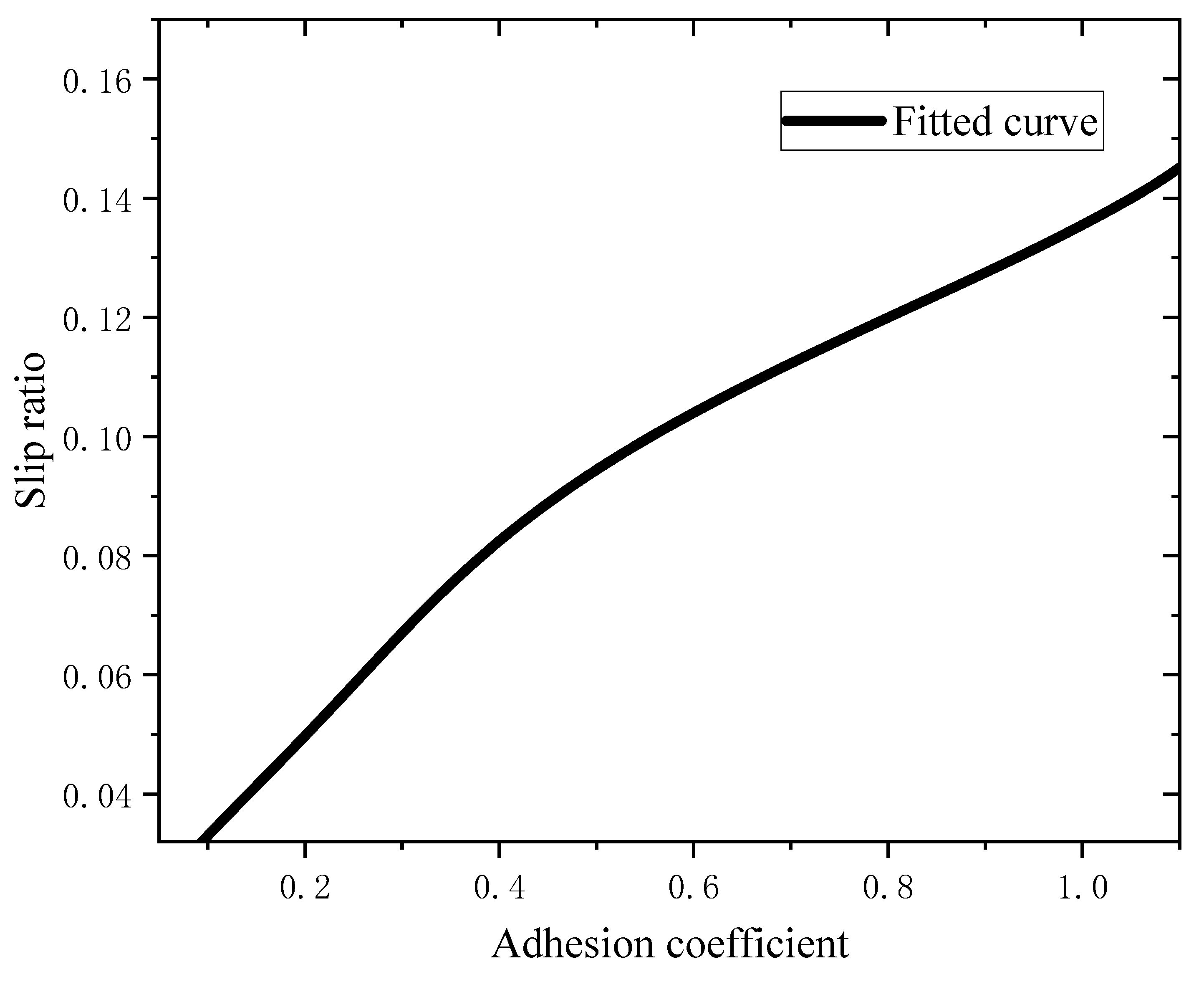
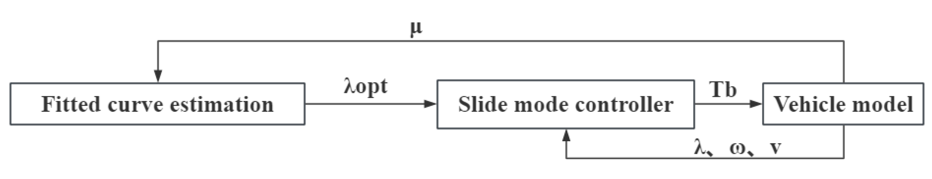
2.5. Road-Surface Recognition Algorithm Design

Mathematical analysis of Equation (4) yields the optimal slip rate λ o p t and peak adhesion coefficient μ m a x for the road surface:
λ o p t = 1 c 2 l n c 1 c 2 c 3
μ m a x = c 1 + c 3 c 2 1     l n c 1 c 2 c 3
The results are shown in Table 2.
The Fourier equation is able to approximate various complex periodic and non-periodic functions with high accuracy in the form of linear combinations of trigonometric functions. The complex nonlinear relationship between ground adhesion and slip rate is effectively fitted by the Fourier equation, which can capture the subtle changes and features in the data. Meanwhile, Fourier analysis has a deep mathematical theoretical foundation, and its properties such as convergence and uniqueness have been rigorously proved mathematically. Based on the λ o p t and μ m a x for each road-surface type, a Fourier equation is used to fit a curve that meets the conditions:
  f x = a 0 + a 1 cos x × w + b 1 sin x × w + a 2 cos 2 x × w + b 2 sin 2 x × w
Using extreme value calculation, we obtain:
a 0 = 0.526 , a 1 = 0.4604 , a 2 = 0.0656 , b 1 = 0.3061 , b 2 = 0.115 , w = 24.3301
Substituting these data into the μ-λ relationship yields the following fitted curve:
  μ λ = 0.526 0.4604 cos λ × 24.3301 0.3061 sin λ × 24.3301   0.0656 cos 2 λ × 24.3301 + 0.1115 sin 2 λ × 24.3301
where 0.032     λ   <   0.17 .
In Figure 3 is the required fitted curve.
This method of fitting curves based on the relationship between the maximum utilization adhesion coefficient and optimal slip rate has the following advantages compared to traditional curve models with slip rate as the horizontal coordinate:
(1) It provides a theoretical basis for obtaining the slip ratio even when the adhesion coefficient is zero;
(2) It allows for direct estimation of the optimal slip ratio when the adhesion coefficient is known;
(3) The method is effective throughout the entire braking process and does not require complex fitting algorithms;
(4) It effectively utilizes the curve model characteristics on different road surfaces.
Therefore, the road-surface information recognition algorithm designed in this paper is simple, clear, and easy to implement. It can quickly adjust the slip rate based on the real-time wheel utilization adhesion coefficient.

2.6. Slip-Rate Control Based on Sliding-Mode Control

Sliding-mode variable-structure control algorithms are widely favored in nonlinear system control due to their fast response and good stability. This section will design a slip-rate controller based on an integral sliding surface to make the vehicle’s actual slip rate quickly and accurately follow the target slip rate [29,30,31].
First, Equation (3) is introduced for the slip rate.
Differentiating the slip rate yields:
λ ˙ = v ˙ ω r v 2 ω ˙ r v
Select the system-state variables as:
z 1 = λ λ * z 2 = t z 1 d t = t ( λ λ * ) d t
where λ is the ideal slip rate and λ * is the actual slip rate.
Select the sliding surface as:
s = z 1 + d z 2
where s is the sliding-surface function of the vehicle wheel, and d is a positive constant.
Differentiating the above equation yields:
s ˙ = λ ˙ λ * ˙ + d λ λ *
When the system operates stably on the sliding surface, s ˙ = 0 , and from the above equation, we obtain:
λ ˙ = λ * ˙ d λ     λ *
Substituting Equation (15) into the above equation, we obtain:
v ˙ ω r v 2 ω ˙ r v = λ * ˙ d λ     λ *
Introduce the exponential approach law:
s ˙ = ε s g n s k s ε , k > 0
where   ε   and k are both positive.
Substituting Equation (21) into Equation (2), we obtain:
  T b = F x r I ω v ˙ v     v λ * r + d λ λ * v r     v r ε s g n s + k s
Lyapunov function is an important tool for determining the stability of a system. For the system in this paper, the stability of the system at the equilibrium point or near a specific trajectory can be directly judged by constructing a suitable Lyapunov function. If we can find a positive definite Lyapunov function whose derivative is negative definite or semi-negative definite along the trajectory of the system, then we can judge that the system is stable. To ensure that the system can reach the sliding surface from any initial state, define the Lyapunov function as:
V = 1 2 s 2
Differentiating the above equation yields:
V ˙ = s s ˙
Substituting s ˙ , we obtain:
V ˙ = ε s k s 2 0
From the Lyapunov stability criterion, the exponential convergence law sliding-mode controller has asymptotic stability, and the error converges to zero in finite time.

3. Results and Discussion

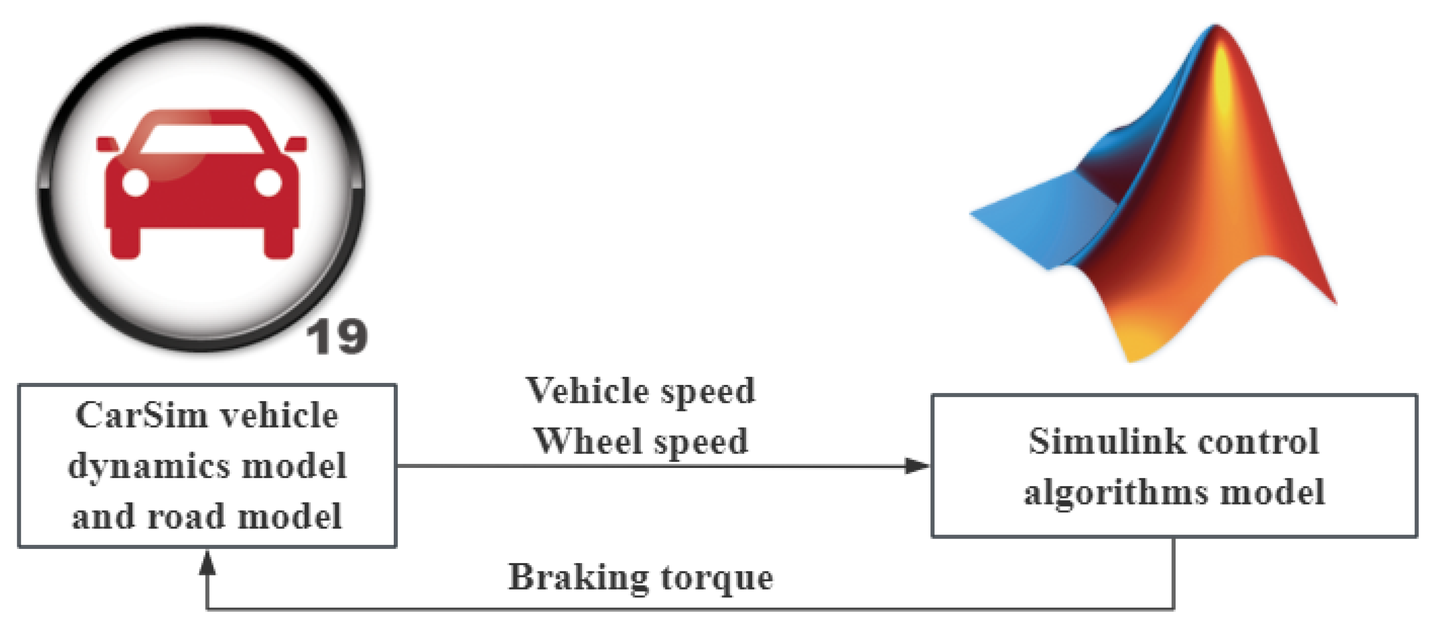
3.1. Simulation Model and Parameter Settings

To verify the effectiveness of the proposed road-surface recognition algorithm and sliding-mode control strategy, we established a joint simulation model based on MATLAB2023a/Simulink and CarSim. Here, the classic C-type vehicle in CarSim is used, while the road is set to be straight and the road-surface adhesion coefficient is variable. Through the simulation interface in Simulink, the vehicle parameters from CarSim are received, the road surface is calculated using the adhesion coefficient, and the fitted curve is used to identify the highest slip rate of the road surface, and then the braking torque of the control wheels is controlled by the slip-film algorithm to control the slip rate to reach the optimal slip rate. Its structure is shown in Figure 4. The co-simulation architecture of CarSim and MATLAB/Simulink is shown in Figure 5.
The main simulation parameters are set as Table 3:

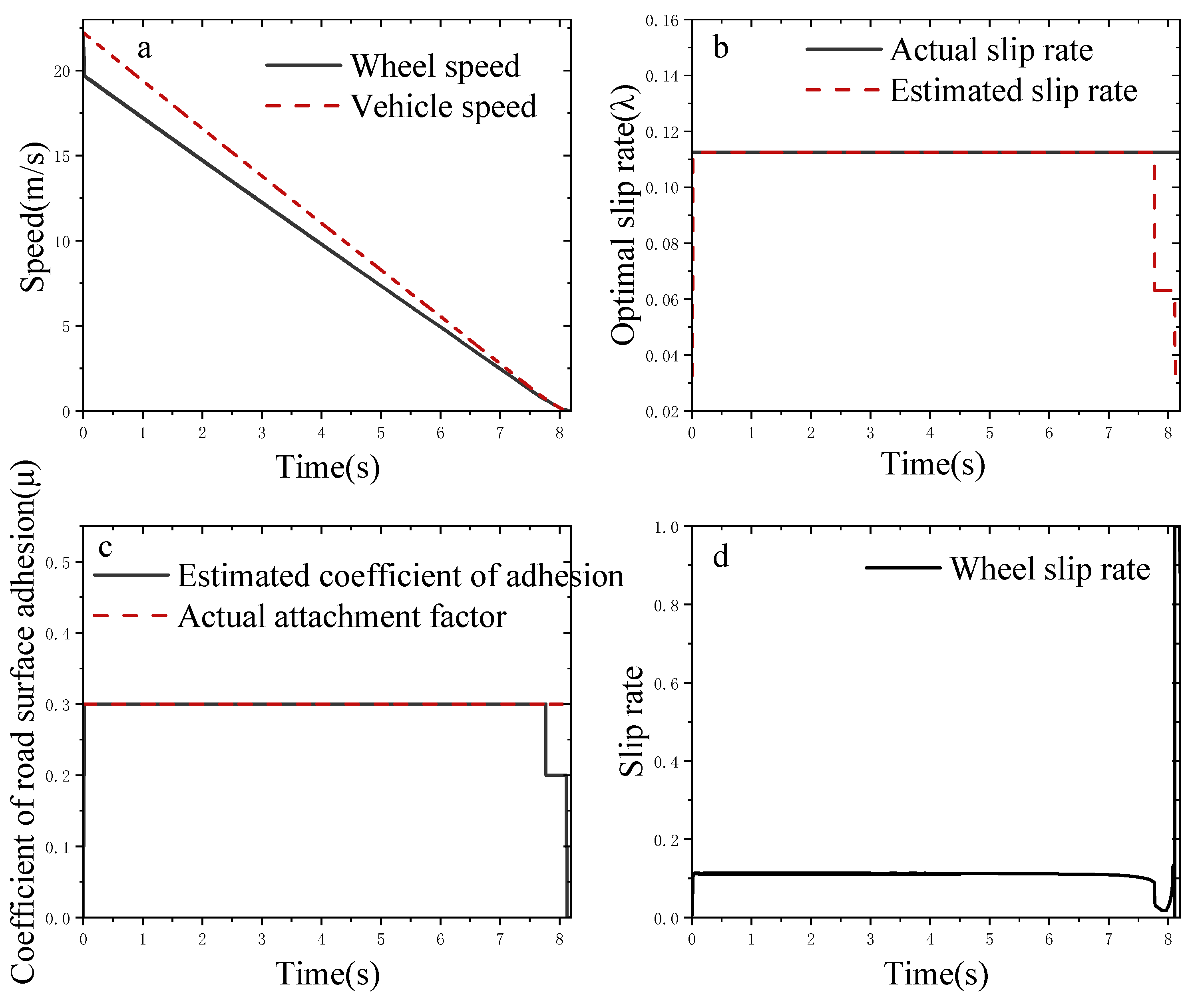
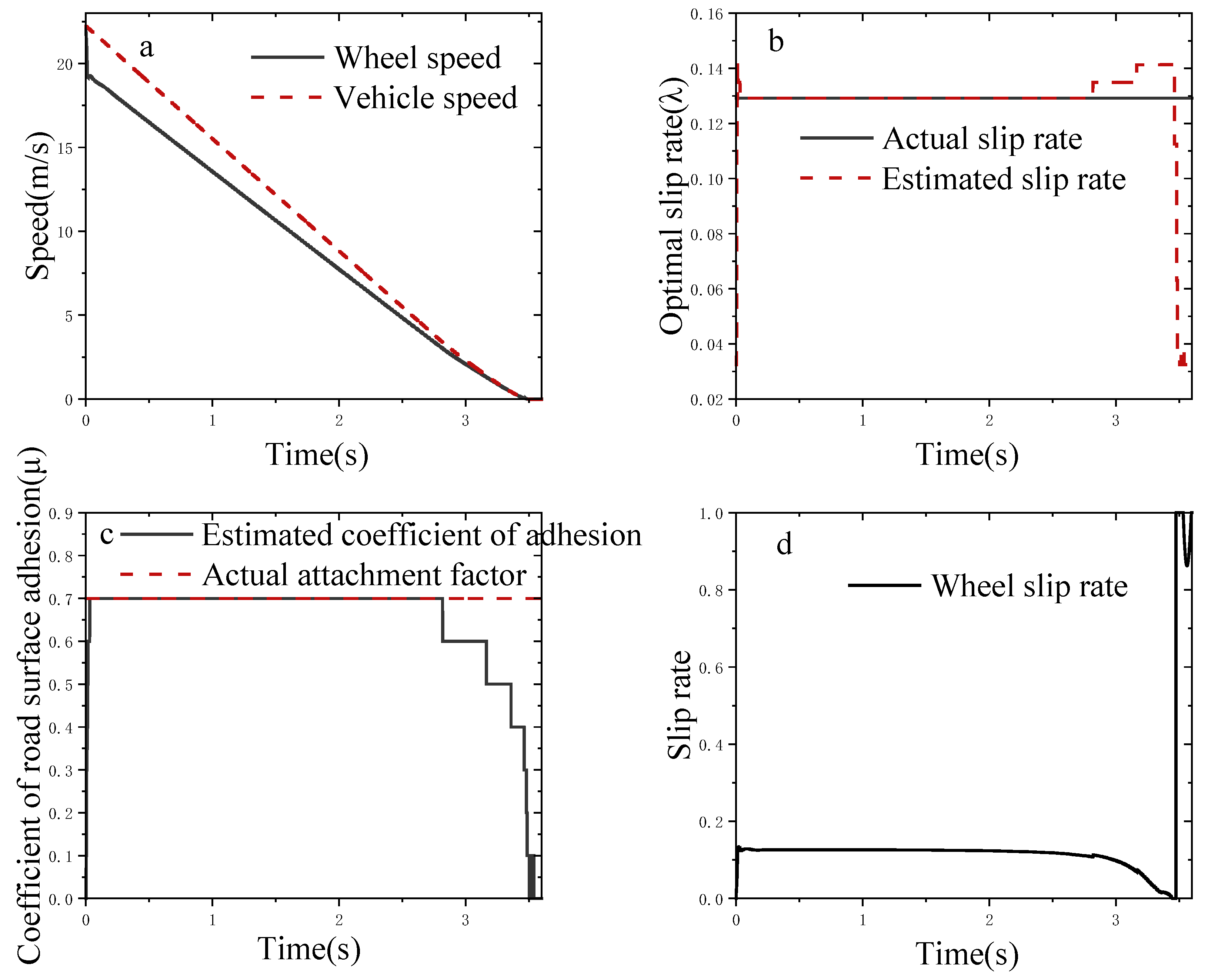
3.2. Simulation Analysis on a Single Road Surface

Simulations were conducted on a road with μ = 0.3, with a target braking intensity of q = 0.5 and an initial vehicle speed of 22.2 m/s. The simulation results are shown in the following figure:
From Figure 6, it can be observed that the vehicle speed is always greater than the wheel speed, and the wheels do not lock up before the vehicle stops. The vehicle and wheel speeds tend to equalize. The road-surface information recognition quickly determines the road adhesion coefficient and optimal slip rate, with the road adhesion coefficient being 0.3 and the wheel slip rate being 0.11. Under these conditions, the road adhesion coefficient does not meet the driver’s braking demand. It can be seen that the anti-lock braking system based on sliding-mode control can effectively control the slip rate around the target slip rate. Near the end of braking, as the wheel speed approaches the vehicle speed and both are close to 0 km/h, the road-surface information cannot accurately identify the road adhesion coefficient and calculate the optimal slip rate. However, considering practical situations, the ABS generally stops when the vehicle speed is below 1.38 m/s, so the designed control strategy can effectively identify the road surface and follow the slip rate.
Simulations were also conducted on a road with μ = 0.7 and target braking intensity q = 0.5. From Figure 7, it can be seen that in the early stage, there is a large fluctuation in the road-surface information recognition of the road adhesion coefficient, but it quickly stabilizes and rapidly estimates the road adhesion coefficient of 0.7 and slip rate of 0.13. Since the target braking intensity is less than the road adhesion coefficient, the road can provide sufficient adhesion for the wheels.

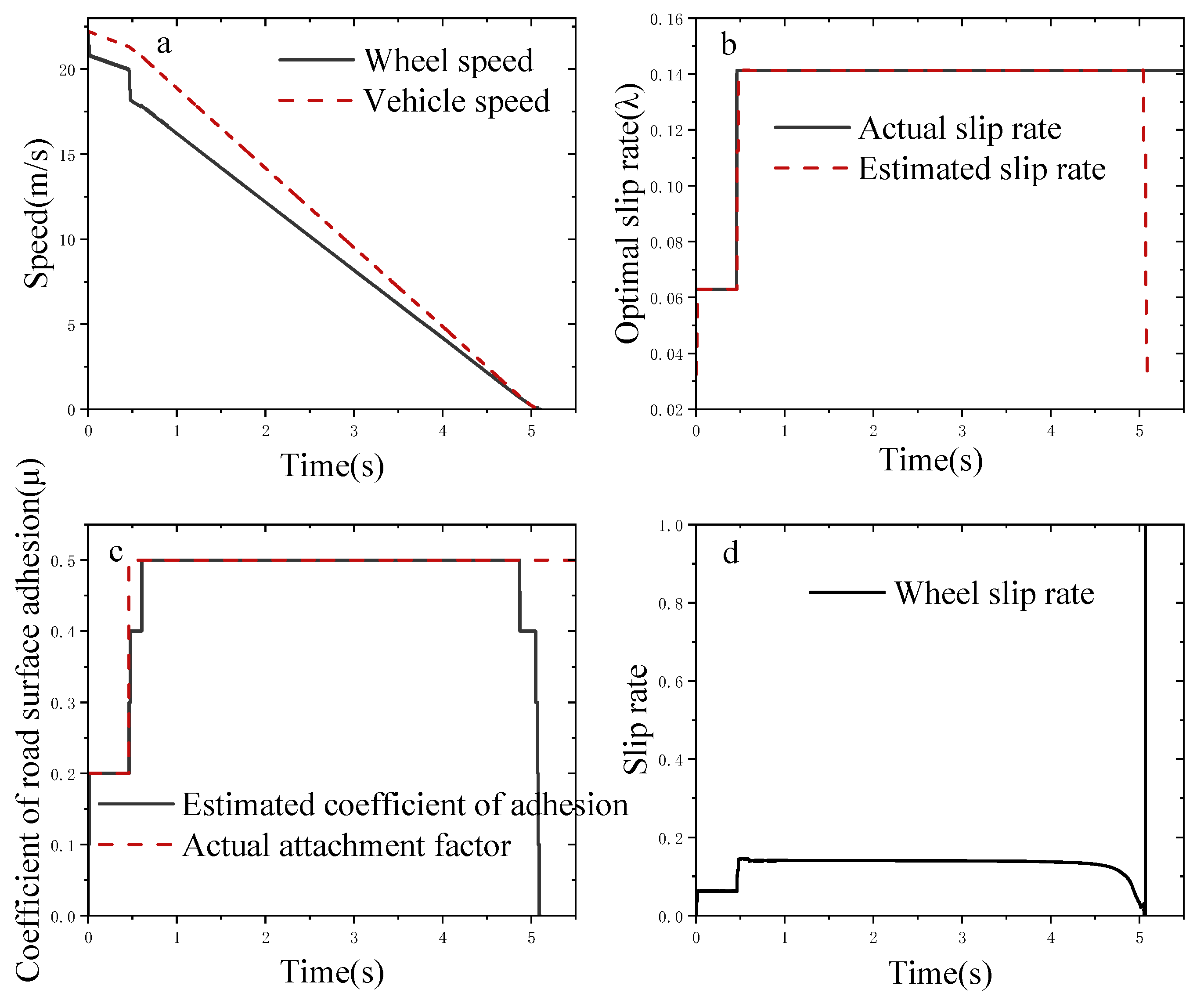
3.3. Simulation Analysis on Changing Adhesion Coefficient Road Surface

Simulations were conducted with a target braking intensity of 0.5, an initial speed of 80 km/h, and two road segments: the first segment with an adhesion coefficient of 0.2, and the second segment with an adhesion coefficient of 0.5. From Figure 8, it can be observed that when entering the first road segment, the adhesion coefficient is less than the braking intensity, so ABS intervenes, and the sliding-mode controller controls the slip rate to maintain it around the target slip rate. When entering the second road segment, the road adhesion coefficient equals the braking intensity, and the wheels do not lock up.

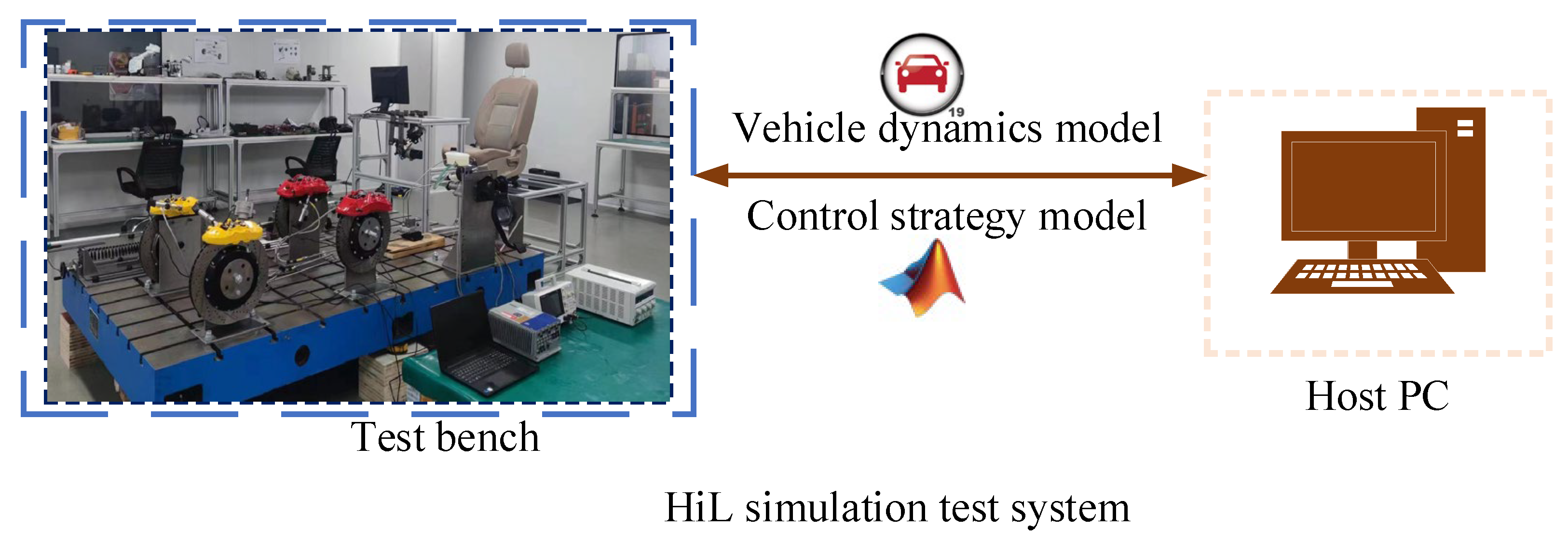
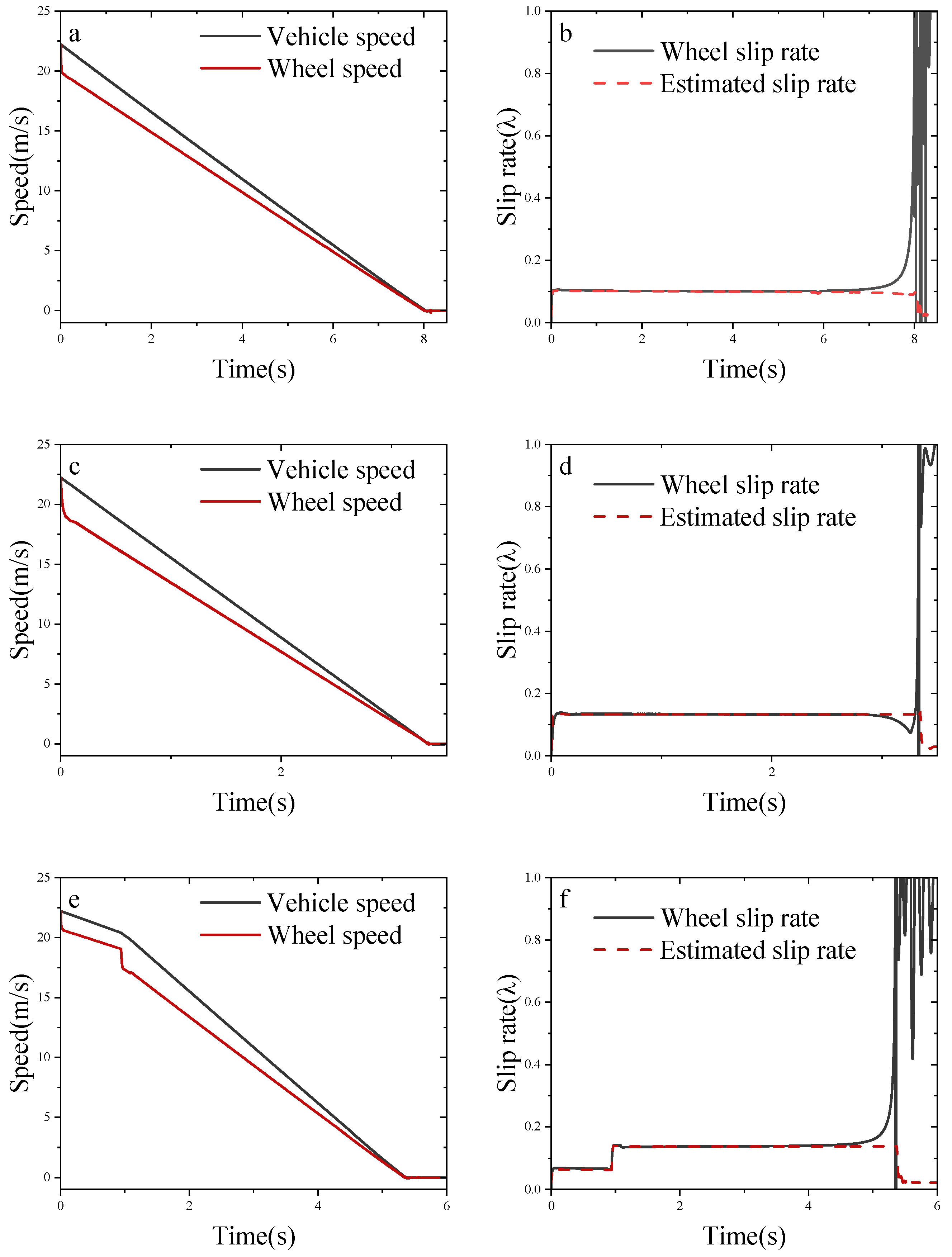
3.4. HiL Simulation Test Results

Build a test bench as shown in Figure 9 as a way to confirm the correctness of the simulation. The tests were conducted using the same conditions as in the joint simulation. For example, the road attachment coefficients were 0.3, 0.7 and 0.2 to 0.5.
From Figure 10, it can be obtained that the slip-mode controller proposed in this paper can control the wheel slip rate following the target slip rate well. When the vehicle is close to stopping, because the speed is too low for the ABS to stop acting, the wheel slip rate will rise to 1. The result of estimating the slip rate is also the same as the previous simulation. The fitted curve and control method proposed in this paper can thus be verified.

4. Discussion

In this paper, the road-surface recognition algorithm and slip-rate control algorithm play a key role in ABS, but there are still some limitations and weaknesses. Firstly, the road-surface recognition can identify the peak adhesion coefficient of the road surface when braking, but it cannot know the road-surface information in advance when not braking. At the same time, when encountering extreme weather, it may affect the sensitivity of the sensors resulting in the inability to accurately identify the road-surface conditions. In the future, the fusion of multi-source sensors can be developed, such as using LIDAR to extract road-surface features for the acquisition of road-surface information, fusing with this paper’s road surface recognition algorithm to improve the algorithm’s ability to recognize complex road-surface conditions and different road-surface materials. Secondly, in terms of the slip-rate control algorithm, it does not take into account the situation of emergency braking when turning at high speed, which is not able to control the slip rate effectively. In the future, a unified vehicle dynamics architecture can be established to achieve synergy between vehicle systems.

5. Conclusions

This paper conducted an in-depth study on the anti-lock braking problem in electronic hydraulic braking systems, focusing on a road-surface recognition algorithm based on fitted curves and a slip-rate control method based on sliding-mode variable structure. The main achievements are as follows:
(1) Proposed a road-surface recognition algorithm based on fitted curves, which can accurately identify the adhesion coefficients of various typical road surfaces, including dry, wet, and icy/snowy surfaces. Through the fitting process of the μ-λ curve, the algorithm demonstrates excellent recognition accuracy and adaptability.
(2) Designed a slip-rate control strategy based on sliding-mode variable structure, fully utilizing the strong robustness of sliding-mode control against system parameter variations and external disturbances. Simulation results show that this control strategy can make the vehicle’s slip rate quickly and accurately converge to the vicinity of the desired optimal slip rate, exhibiting good control effects under different road conditions.
(3) Verified the effectiveness and robustness of the proposed method through simulation analysis on single road surfaces and changing-adhesion-coefficient road surfaces. The results show that the system can maintain stable braking performance under complex road conditions, effectively improving vehicle braking safety.
This study provides an efficient and reliable technical solution for anti-lock braking control in electronic hydraulic braking systems, with significant theoretical and practical implications for enhancing vehicle braking safety. Future research directions may include:
(1) Considering more complex vehicle dynamics models, such as incorporating the effects of lateral forces.
(2) Exploring the combination of machine learning techniques with sliding-mode control to further improve the system’s adaptive capabilities.
(3) Conducting real vehicle tests to verify the performance of the proposed method under actual road conditions.

Author Contributions

Conceptualization, H.Z. and R.W.; methodology, W.L. (Wenguang Liu); software, R.D.; validation, Z.G. and Q.Y.; formal analysis, X.M.; investigation, D.S.; resources, W.L. (Wei Liu); data curation, H.Z.; writing—original draft preparation, H.Z.; writing—review and editing, H.Z.; visualization, H.Z.; supervision, H.Z.; project administration, H.Z.; funding acquisition, H.Z. All authors have read and agreed to the published version of the manuscript.

Funding

This research received no external funding.

Institutional Review Board Statement

Not applicable.

Informed Consent Statement

Not applicable.

Data Availability Statement

The original contributions presented in this study are included in the article. Further inquiries can be directed to the corresponding author.

Conflicts of Interest

Z.G. is employee of Jiangsu Chaoli Electric Co., Ltd. The remaining authors declare that the research was conducted in the absence of any commercial or financial relationships that could be construed as a potential conflict of interest.

References

  1. Zhao, X.; Xiong, L.; Zhuo, G.; Tian, W.; Li, J.; Shu, Q.; Zhao, X.; Xu, G. A Review of One-Box Electro-Hydraulic Braking System: Architecture, Control, and Application. Sustainability 2024, 16, 1049. [Google Scholar] [CrossRef]
  2. Li, M.; Wang, H.; Chen, Y. Advanced braking systems in modern vehicles: A comprehensive review. IEEE Trans. Veh. Technol. 2019, 68, 4074–4093. [Google Scholar]
  3. Kim, S.; Lee, J.; Yi, K. Development of an electronic hydraulic brake system for improved braking performance. SAE Int. J. Passeng. Cars Mech. Syst. 2018, 11, 241–253. [Google Scholar]
  4. Robert Bosch GmbH. Automotive Handbook, 10th ed.; Wiley: Hoboken, NJ, USA, 2018. [Google Scholar]
  5. Rajamani, R. Vehicle Dynamics and Control, 2nd ed.; Springer: Berlin/Heidelberg, Germany, 2012. [Google Scholar]
  6. Mauer, G.F. A fuzzy logic controller for an ABS braking system. IEEE Trans. Fuzzy Syst. 1995, 3, 381–388. [Google Scholar] [CrossRef]
  7. Wang, J.; Song, J.; Che, H. A review of ABS control algorithms: From logic threshold to intelligent control. Veh. Syst. Dyn. 2018, 56, 1129–1151. [Google Scholar]
  8. Unsal, C.; Kachroo, P. Sliding mode measurement feedback control for antilock braking systems. IEEE Trans. Control Syst. Technol. 1999, 7, 271–281. [Google Scholar] [CrossRef]
  9. Siddique, M.A.A.; Kim, W.-S.; Kim, Y.-S.; Kim, T.-J.; Choi, C.-H.; Lee, H.-J.; Chung, S.-O.; Kim, Y.-J. Effects of temperatures and viscosity of the hydraulic oils on the proportional valve for a Rice transplanter based on PID control algorithm. Agriculture 2020, 10, 73. [Google Scholar] [CrossRef]
  10. Xu, F.; Liang, X.; Chen, M.; Liu, W. Robust self-learning PID control of an aircraft anti-skid braking system. Mathematics 2022, 10, 1290. [Google Scholar] [CrossRef]
  11. Chen, J.; Wang, G.; Zhao, C.; Song, J. A PID control strategy research of vehicle ABS braking based on slip. In Proceedings of the 5th International Conference on Traffic Engineering and Transportation System (ICTETS 2021), Chongqing, China, 24–26 September 2021; p. 39. [Google Scholar]
  12. Quan, V.H.; Long, L.T.; Ngoc, N.A.; Tien, N.M. A comparison of the performance of anti-lock braking system (ABS) using fuzzy and PID controllers. In Proceedings of the 6th International Conference on Green Technology and Sustainable Development (GTSD), Nha Trang City, Vietnam, 29–30 July 2022; pp. 243–248. [Google Scholar]
  13. Chen, S.; Zhang, X.; Wang, J. Sliding mode control of vehicle equipped with brake-by-wire system considering braking comfort. Shock Vib. 2020, 2020, 5602917. [Google Scholar] [CrossRef]
  14. Jeong, Y. Path tracking control for four-wheel-steering autonomous vehicles based on adaptive sliding mode control with control allocation. In Proceedings of the 21st International Conference on Control, Automation and Systems (ICCAS), Jeju, Republic of Korea, 12–15 October 2021; pp. 1741–1746. [Google Scholar]
  15. Hongbo, W.; Boyang, Z.; Jinfang, H.; Jiahao, X.; Linfeng, Z.; Xianjun, Y. Road surface recognition based slip rate and stability control of distributed drive electric vehicles under different conditions. Proc. Inst. Mech. Eng. Part D J. Automob. Eng. 2023, 237, 2511–2526. [Google Scholar] [CrossRef]
  16. Ho, C.C.; Ulfitria, R.U.S. Automatic anti-lock brake system for anti-rollover control of autonomous heavy-duty truck. In Proceedings of the 2022 IEEE International Conference on Consumer Electronics, Taipei, Taiwan, 6 July 2022; pp. 181–182. [Google Scholar]
  17. El-Fatah, S.A.; Sharkawy, A.-N.; Ghazaly, N.; Moaaz, A. A comparative study of different control methods for anti-lock braking system (ABS). SVU-Int. J. Eng. Sci. Appl. 2021, 2, 27–34. [Google Scholar] [CrossRef]
  18. Han, K.; Lee, B.; Choi, S.B. Development of an antilock brake system for electric vehicles without wheel slip and road friction information. IEEE Trans. Veh. Technol. 2019, 68, 5506–5517. [Google Scholar] [CrossRef]
  19. Kang, Y.; Cheng, S.; Guo, L.; Zheng, C.; Zhao, J. An Adaptive Multi-Layer Anti-Lock Braking Control Method Based on Fuzzy Logic. IEEE Access 2024, 12, 149468–149480. [Google Scholar] [CrossRef]
  20. Guo, H.; Zhao, X.; Liu, J.; Dai, Q.; Liu, H.; Chen, H. A fusion estimation of the peak tire–road friction coefficient based on road images and dynamic information. Mech. Syst. Signal Process. 2023, 189, 110029. [Google Scholar] [CrossRef]
  21. Yan, J.; Kong, H.; Man, Z. Recurrent neural network-based nonlinear optimization for braking control of electric vehicles. Energies 2022, 15, 9486. [Google Scholar] [CrossRef]
  22. Hamou, A.A.; Khaled, M.; Cylia, A.; Billel, N. Comparative study of the intelligent techniques (fuzzy logic and neural network) of the ABS system. In Proceedings of the 19th International Multi-Conference on Systems, Signals & Devices (SSD), Sétif, Algeria, 6–10 May 2022; pp. 1497–1503. [Google Scholar]
  23. Li, M.; Li, S.; Ahn, C.K.; Xiang, Z. Adaptive fuzzy event-triggered command-filtered control for nonlinear time-delay systems. IEEE Trans. Fuzzy Syst. 2022, 30, 1025–1035. [Google Scholar] [CrossRef]
  24. Liu, Y.; Sun, J.; Li, L. A review on development of electronic hydraulic brake system. Automot. Eng. 2019, 41, 881–893. [Google Scholar]
  25. Cao, W. Modeling and simulation of the anti-lock braking system based on MATLAB/Simulink. J. Phys. Conf. Ser. 2021, 1941, 012075. [Google Scholar] [CrossRef]
  26. Zhang, W. Automotive Theory; Machinery Industry Press: Beijing, China, 2005. [Google Scholar]
  27. Unguritu, M.G.; Nichitelea, T.C. Design and Assessment of an Anti-lock Braking System Controller. Rom. J. Inf. Sci. Technol. 2023, 26, 21–32. [Google Scholar] [CrossRef]
  28. Kiencke, U.; Nielsen, L. Automotive Control Systems; Springer: Berlin/Heidelberg, Germany, 2005. [Google Scholar]
  29. Liu, Y.; Pei, X.; Guo, X. Redundancy Control of Anti-lock Braking System Based on Electro-hydraulic Braking System. SAE Int. J. Veh. Dyn. Stab. NVH 2023, 7, 53–67. [Google Scholar] [CrossRef]
  30. Yang, F.; Chen, X.; Guo, D.; Hu, M.; Liao, Z.; Fu, Z.; Gong, Q. Electric-hydraulic Compound Control Anti-lock Braking System. Int. J. Automot. Technol. 2022, 23, 1593–1608. [Google Scholar] [CrossRef]
  31. Jennan, N.; Mellouli, E.M. Anti-Lock Braking System Control using Backstepping Method Based Fuzzy Logic. Sens. Transducers 2023, 261, 10–14. [Google Scholar]
Figure 1. Single-wheel model.
Wevj 16 00156 g001
Figure 2. Standard road-surface μ λ curves.
Wevj 16 00156 g002
Figure 3. Fitted μ m a x - λ o p t t curve.
Wevj 16 00156 g003
Figure 4. Slip-rate sliding-mode control based on fitted curves.
Wevj 16 00156 g004
Figure 5. CarSim and MATLAB/Simulink co-simulation architecture.
Wevj 16 00156 g005
Figure 6. A simulation of a road-surface adhesion coefficient of 0.3: (a) comparison of vehicle speed and wheel speed; (b): comparison of actual slip rate and estimated slip rate; (c): actual road-surface adhesion coefficient and calculated adhesion coefficient; (d): actual wheel slip rate.
Wevj 16 00156 g006
Figure 7. A simulation of a road-surface adhesion coefficient of 0.7: (a) comparison of vehicle speed and wheel speed; (b): comparison of actual slip rate and estimated slip rate; (c): actual road-surface adhesion coefficient and calculated adhesion coefficient; (d): actual wheel slip rate.
Wevj 16 00156 g007
Figure 8. A simulation of a road-surface adhesion coefficient of 0.2–0.5: (a) comparison of vehicle speed and wheel speed; (b): comparison of actual slip rate and estimated slip rate; (c): actual road-surface adhesion coefficient and calculated adhesion coefficient; (d): actual wheel slip rate.
Wevj 16 00156 g008
Figure 9. HiL simulation test system.
Wevj 16 00156 g009
Figure 10. (a): Road-surface adhesion coefficient of 0.3, comparison of vehicle speed and wheel speed; (b): road-surface adhesion coefficient of 0.3, comparison of estimated slip rate and wheel slip rate; (c): road-surface adhesion coefficient of 0.7, comparison of vehicle speed and wheel speed; (d): road-surface adhesion coefficient of 0.7, comparison of estimated slip rate and wheel slip rate; (e): road-surface adhesion coefficient of 0.2–0.5, comparison of vehicle speed and wheel speed; (f): road-surface adhesion coefficient of 0.2–0.5, comparison of estimated slip rate and wheel slip rate.
Wevj 16 00156 g010
Table 1. Fitting parameters for standard road surfaces.
Road Type c 1 c 2 c 3
Dry Asphalt1.280123.990.52
Wet Asphalt0.85733.8220.347
Dry Concrete1.197325.1680.5373
Snow0.194694.1290.0646
Ice0.05306.390
Table 2. Peak adhesion coefficients and optimal slip rates for standard road surfaces.
Road SurfacesDry AsphaltDry ConcreteWet AsphaltSnowIce
Parameter
μ m a x 1.1711.0890.8000.1900.050
λ o p t 0.1700.1600.1310.0600.032
Table 3. Detailed parameters.
Parameter NameValue
Vehicle weight/kg m 1412
Sprung mass/kg m c 1270
Wheel rotational inertia/kg·m2  I 0.9
Height of sprung mass center of gravity/m h c 0.54
Front and rear tire mass/kg m u f   m u r 71
Distance from center of gravity to front axle/m l a 1.015
Distance from center of gravity to rear axle/m l b 1.895
Distance between front and rear axles/m l 2.91
Disclaimer/Publisher’s Note: The statements, opinions and data contained in all publications are solely those of the individual author(s) and contributor(s) and not of MDPI and/or the editor(s). MDPI and/or the editor(s) disclaim responsibility for any injury to people or property resulting from any ideas, methods, instructions or products referred to in the content.

