Article

Application Layer Software Design of Vehicle Comfort Braking Based on Brake-by-Wire System

School of Mechanical and Automotive Engineering, Shanghai University of Engineering Science, Shanghai 201620, China
*
Author to whom correspondence should be addressed.
World Electr. Veh. J. 2023, 14(8), 220; https://doi.org/10.3390/wevj14080220
Submission received: 5 July 2023 / Revised: 9 August 2023 / Accepted: 11 August 2023 / Published: 15 August 2023

Abstract

:
With the development of the brake-by-wire system, more and more advanced driver assistance systems have been applied to automobiles. The brake-by-wire system can collect the driver’s braking intention through the displacement sensor and thus realize accurate braking by the motor. Based on the brake-by-wire system, we design an algorithm that can realize the vehicle Comfort Stop Technology (CST) in this paper. The CST can control the drop and rise of brake fluid pressure during the braking stop of the vehicle, and therefore reduce the sharp feeling of front and back pitching during the braking stop. Finally, through real car verification, the functional algorithm designed in this paper can improve the nodding feeling of the vehicle by reducing the deceleration of the vehicle during braking.

1. Introduction

The development of vehicle electrification and intelligence has promoted the development and research of many vehicle active control functions [1,2]. Although traditional hydraulic braking technology is very mature, with the improvement of braking performance requirements, some functions such as Hill-Start Assist Control (HAC), Electronic Stability Control (ESC), and Automatic Emergency Braking System (AEB) have been integrated into the braking system, and the traditional braking system is no longer suitable for the realization of these functions. As one of the key components to realizing the intelligent driving assistance function, the brake-by-wire system can not only realize the decoupling of pedal force and braking force but also has a fast braking response speed of 100 ms–200 ms [3,4]. The brake-by-wire system provides better control of pedal stiffness, vehicle stability, and brake force distribution than a conventional hydraulic or electrohydraulic system [5]. At the same time, as an important part of intelligent networked electric vehicles, the wire-controlled dynamic system is the key to determining vehicle performance and braking energy recovery efficiency. The wire-controlled dynamic system has undergone great changes in structure and control methods, which greatly improves vehicle safety and energy recovery efficiency, and integrates more functions [6]. Ji [7] established the pedal simulator simulation model and then adjusted the simulator parameters to evaluate the pedal simulator and braking sensation of the linear control dynamic system. Laaleh Durali [8] designed a braking system for a cam-driven mechanism that maximizes the characteristics of the motor torque by combining electrical and hydraulic components, which can be fitted to each wheel and can be independently controlled for individual wheels, resulting in better stability of the vehicle during rapid acceleration or emergency braking. Ma [9] proposed a novel structure of a combined braking system based on regenerative braking energy, built a simulation model through Simulink to analyze the dynamic parameters such as the initial braking speed and the maximum braking pressure of the vehicle, and concluded that the initial braking speed of the vehicle is the key to affecting the total efficiency of braking energy recovery. The precise control of the hydraulic pressure of the wheel cylinder is a key technology of the linear control system. Zhao [10] designed a solenoid valve spool position control method based on sliding mode variable structure, and the algorithm was verified by simulation and hardware-in-the-loop experiment. The simulation results show that the brake cylinder pressure can be estimated accurately, and the pressure control algorithm can follow the control target value accurately. At the same time, the brake-by-wire system can realize many active control functions. Seo [11] proposed a wheel cylinder fluid pressure control algorithm for the control of the vehicle’s electronic stability system. The brake fluid pressure of each wheel is controlled separately through the on–off solenoid valve to ensure the stability of the vehicle under various working conditions. Bao [12] designed a vehicle dynamics model, a model related to the rate of change in braking pressure and braking smoothness, and analyzed the effect of the rate of change in pressure between the single brake chamber of the front and rear axles and the coaxial same-side brake chamber on the braking smoothness of commercial vehicles through simulation and comparison. Seina Kosak [13] linearized the vehicle braking system and then designed a driver braking control model based on LQ control theory, which could make the vehicle stop within the target distance under certain ride comfort conditions. Wu [14] established a vehicle-following braking comfort model, which could calculate appropriate deceleration based on the distance between front and rear vehicles and the speed of the controlled vehicle, so as to achieve a comfortable braking stop feeling. With the development of new energy vehicles, vehicles driven by wheel motors have attracted more and more attention. The introduction of wheel motors will change the proportion of unsprung mass, affecting the ride comfort of vehicles. Jin [15] proposed a proportional–integral–derivative control system for semi-active air suspension. It proved that the control strategy could improve the ride comfort of vehicles driven by wheel hub motors through simulation and real vehicle tests. Zhao [16] proposed a comfort-based braking force distribution algorithm by considering the driver’s braking demand and the motor’s maximum braking torque and proved through experiments that the braking force distribution strategy can effectively improve the braking comfort of electric vehicles. In order to further improve the safety and comfort of brake-by-wire and give full play to the key role of wire control chassis in the field of intelligent driving, we built the Comfort Stop Technology (CST) model through Matlab/Simulink software on the basis of the brake-by-wire system in this paper, then converted it into C code and wrote it into the controller of the brake by wire system, and finally carried out the parameter calibration of the CST. In this way, the vehicle comfort braking function can be realized at a smaller cost, the algorithm parameters can be quickly adjusted according to different models, and the embedded software is written into the controller of the brake-by-wire system, which is convenient for secondary development. It is found that CST can control the deceleration of the vehicle by adjusting the brake fluid pressure reasonably, to achieve the purpose of comfortable parking.

2. Basic Principle of Brake-by-Wire System

The brake-by-wire system is developed based on traditional vacuum boosters and hydraulic brakes. The functional principle of the line control dynamic system is that the vacuum booster is replaced by a permanent magnet synchronous motor, the pedal displacement sensor collects the driver’s braking intention, the pedal displacement information is transmitted to the electronic control unit, and then the corresponding brake fluid pressure is analyzed by the control algorithm to realize the motor power and the decoupling of pedal force and wheel cylinder pressure [17,18]. Because the final brake pressure is assisted by the motor, which enables the line control system to achieve a variety of ADAS functions, line control technology has become the basis of autonomous driving. The brake-by-wire system is mainly composed of a pedal sensation simulator, brushless housing, permanent magnet synchronous motor, transmission assembly, master cylinder, and brake fluid oil pot [19]. The corresponding brake-by-wire system structure is established in Figure 1.

3. Basic Principle of Comfort Stop Technology

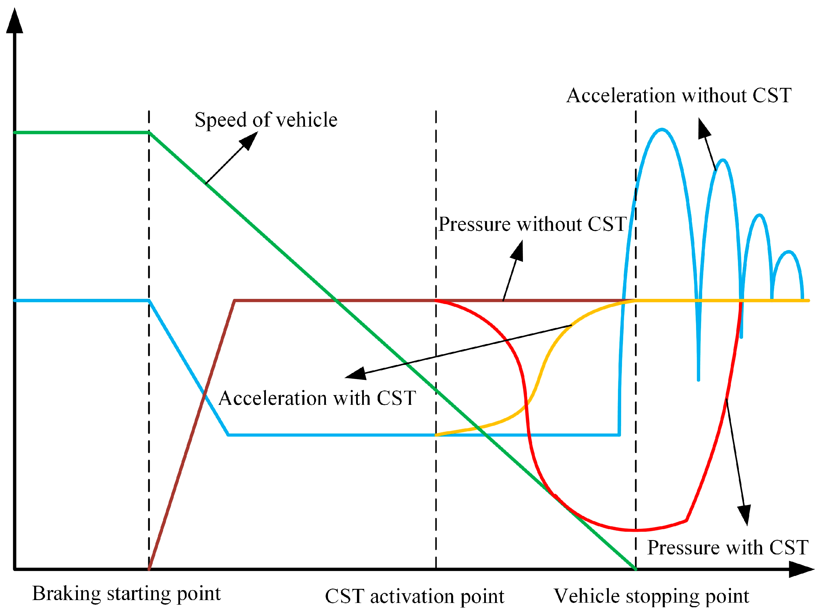
When a vehicle brakes, especially emergency braking, the instantaneous inertia of the vehicle will cause passengers intense discomfort, so the study of the vehicle comfort in the braking process is of great significance to improve the performance of the vehicle [20,21]. CST is needed to improve the driving experience during braking and reduce the angle and frequency of the front and rear pitch of the vehicle. Under the premise of ensuring the vehicle’s safety, CST can relieve the pressure of the brake fluid and control the recovery to change the vehicle’s deceleration when stopping. The variables during a CST operation are shown in Figure 2.
The brake-by-wire system will relieve pressure on the premise that the vehicle is safe. The corresponding minimum pressure relief value needs to be determined by the real vehicle calibration [22], to ensure that the vehicle will not have insufficient braking after relieving pressure on the sloping road, resulting in dangerous situations such as sliding slopes. After the vehicle stops statically, the brake pressure will return to the target fluid pressure according to a particular slope to solve the problem of sharp front and back pitching when the vehicle stops.

4. CST Software Module Design

In this paper, the CST module was set up based on Matlab/Simulink software, and the function modules and Stateflow state machine were automatically converted into C code to be embedded in the engineering code package of the brake-by-wire system. The Tasking tool compiled the embedded integrated software and burned it into the main control chip of the brake-by-wire system. The overall architecture of CST software designed in this paper is shown in Figure 3.
The role of the brake software module in the brake-by-wire system is to parse the driver’s braking intent and convert it into the target brake fluid pressure. In Figure 3, the brake software module input signals include the EHB fault state signal and input target fluid pressure signal; CAN bus input signals refer to the signals sent by the vehicle CAN network to the brake-by-wire system, including vehicle acceleration, road slope, gear signal, front-wheel Angle, ABS status, and speed signal.
The CST module consists of three parts: the function enable judgment module, the function status judgment module, and the target liquid pressure control module. In the entire software architecture of the brake-by-wire system, the CST module is between the brake software module (BSM) and the liquid pressure control module (PCM). The CST module will control the total brake pressure analyzed by the brake software module. The processed target fluid pressure is then fed to the fluid pressure control module to change its output motor torque value.
The liquid pressure control logic in the CST module is as follows:
Set P b _ d r i v e r = f ( α ) , where P b _ d r i v e r is the driver’s target fluid pressure; the calculation formula is shown in Equation (1):
P p _ min = 2 G R sin θ π μ ( d 1 2 r 1 + d 2 2 r 2 )
where G is the gravity of the vehicle; R is the radius of the wheel; θ is the slope; μ is the friction coefficient between the brake friction liner and the brake disc; d 1 , d 2 is the equivalent cylinder diameter of the front and rear brake wheel cylinders; and r 1 , r 2 is the distance from the center of the front and rear brake wheel cylinders.
The actual output target liquid pressure formula is:
P b 0 = δ P p _ min ( θ ) + 1 2 [ P b _ d r i v e r ( α ) P p _ min ( θ ) ]
where P b 0 is the target fluid pressure of the temporary parking state when the slope is not sliding; δ is the safety factor, δ >1.
When the speed is not 0, it is judged that slope slip occurs, the number of slope slips is 1, and the normal braking mode is immediately switched. The next time the vehicle enters temporary parking mode, the actual output target fluid pressure is:
P b 1 = δ P p _ min ( θ ) + 3 4 [ P b _ d r i v e r ( α ) P p _ min ( θ ) ]
where A is the target liquid pressure of the temporary parking state during slope sliding for one time.
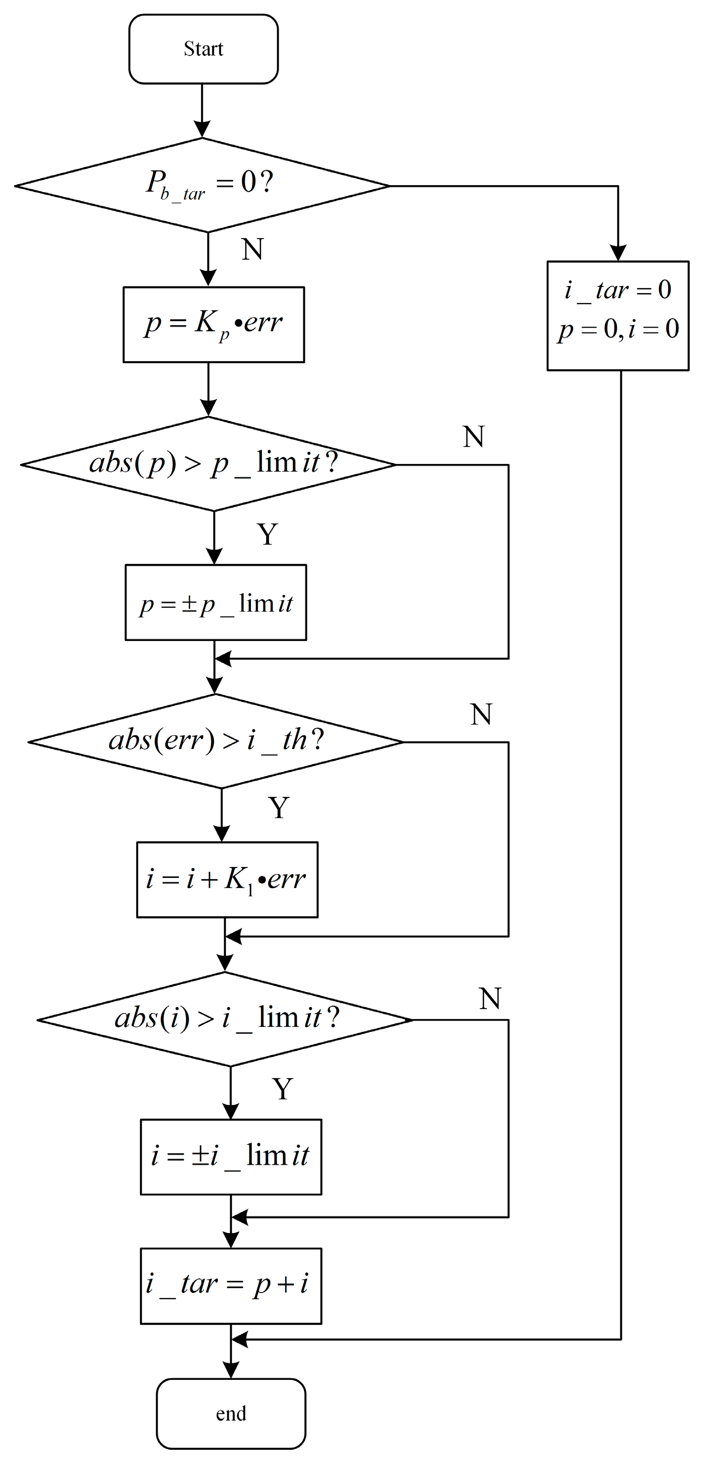
The corresponding flow of the liquid pressure control algorithm is shown in Figure 4.
In Figure 4, the scale coefficient K p , the scale threshold p _ lim i t , the integral separation threshold i _ t h , and the integral threshold i _ lim i t need to undergo parameter tuning. P b _ t a r is the target fluid pressure, e r r is the difference between actual hydraulic pressure and target value, i _ t a r is the actual liquid pressure resolved, and K 1 is the Scale factor.

4.1. The Design of Function Enable Judgment Module

4.1.1. Signal Processing Module

Before enabling the CST input signal, it is necessary to perform signal processing on the corresponding signal. Low-pass filtering is mainly performed on the road slope collected by the sensor when the vehicle is running to improve the processing accuracy of the subsequent module [23,24]. The basic theoretical formula of low-pass filtering is:
y ( t ) = y ( t 1 ) + K × [ u ( t ) y ( t 1 ) ]
where K is the filter coefficient, generally between 0 and 1, u is the input signal, and y is the output signal. In this paper, the filter model architecture for the input slope signal is shown in Figure 5, wherein the input of filter module 1 is the initial slope signal and filter coefficient 1, which is obtained from the one-dimensional table of the vehicle speed. The slope signal of the second segment is finally output, and the corresponding filter module 1 is shown in Figure 6. The input of filtering module 2 is the second stage slope signal and filtering coefficient 2, which is obtained by looking up the difference between the final output slope and the initial slope, and the output is the final filtered slope signal, as shown in Figure 7.

4.1.2. Signal Processing Module

When CST is activated, the brake fluid pressure drops from the initial target brake fluid pressure to the minimum target value, then rises to the original initial fluid pressure at a calibrated rate of return, and the whole process of change will be completed within 2 s. When the vehicle activates the Anti-lock Braking System (ABS) or Electronic Brakeforce Distribution (EBD), the brake fluid pressure fluctuates up to a maximum of about 200 bar. It will affect the driving stability and comfort of the vehicle [25]. Therefore, it is necessary to judge the enabling conditions of CST according to the brake module and bus signal of the brake-by-wire system. The signals that need to be collected include front wheel angle, lateral acceleration, longitudinal acceleration, road slope, gear signal, input target liquid pressure, EBD state, ABS state, EHB fault state, vehicle ignition signal, and speed signal. When the above signal values are within the range of calibration values, the brake-by-wire system detects that ABS and EBD are not activated, and the sign bit of the vehicle speed is on. It determines that the enable bit of the CST function is on. Otherwise, the CST function is disabled.

4.2. The Design of CST Function Status Judgment Module

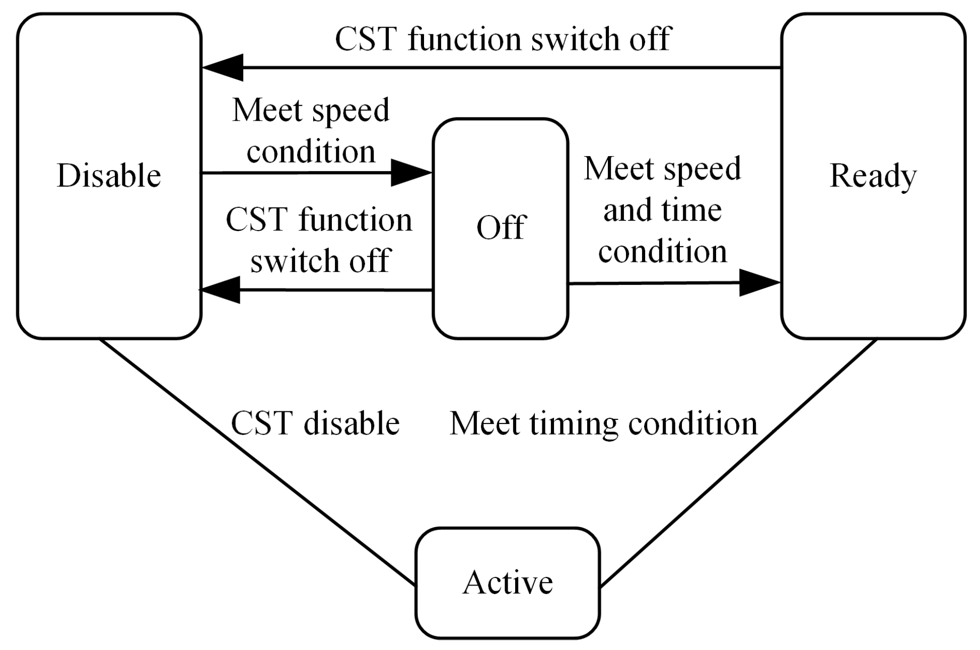
The primary function of the CST function status judgment module is to judge the current functional status of the CST according to the function status, the time threshold when the vehicle enters the static state, and the speed signal. The CST function status can be Disable, Off, Ready, and Active. The status judgment module designed in this paper is established in Figure 8.

4.3. The Design of Target Liquid Pressure Control Module

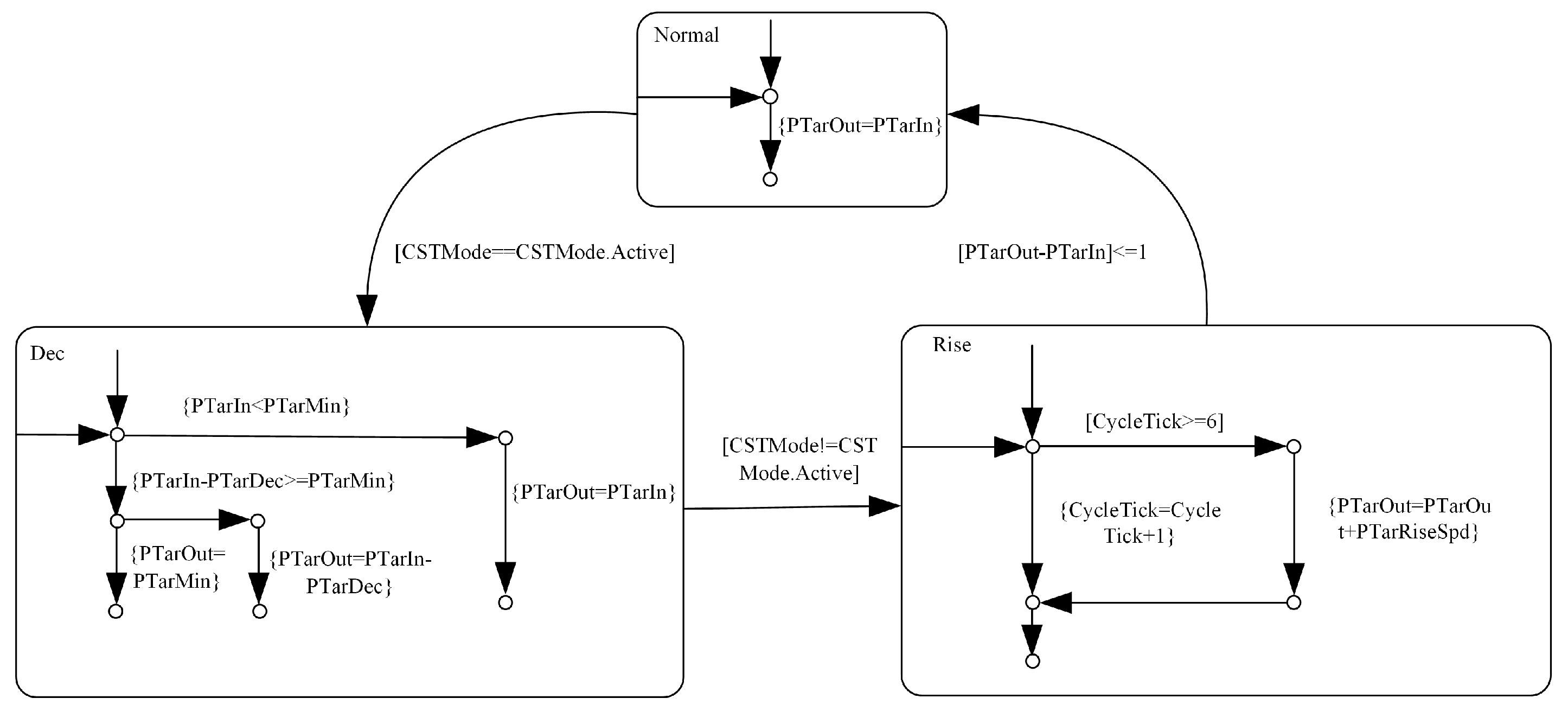
The target liquid pressure control module is the core module of CST to realize the final function. The input signals include the CST function status signal, input target liquid pressure, pressure relief value, pressure recovery rate, and target minimum pressure relief value signal. In order to improve the universality and flexibility of the software for various types of vehicles, the software inputs the pressure relief value to the target liquid pressure control module as a table lookup process, mainly according to the speed and input target liquid pressure signal to obtain the corresponding pressure relief value. In order to ensure the comfort of vehicle braking, the slope of the pressure relief curve after calibration is gradually reduced [26]. At the same time, when the road surface has a corresponding slope, if the target minimum pressure relief value is not treated at this time, insufficient brake fluid pressure will lead to slope risk [27], so the minimum pressure relief value compensation strategy is designed in the software. That is, the corresponding liquid pressure compensation value is checked according to the slope information, and the corresponding table value is determined by the real vehicle calibration. According to whether CST is in the Active state and the difference between the input target liquid pressure and the output target liquid pressure of CST, the target liquid pressure control module will complete the jump between the three state machines of target liquid pressure relief, boost, and normal output. The corresponding state machine process is shown in Figure 9.
When CST is in a Normal state, the target liquid pressure will not be processed, and the output target liquid pressure of CST is equal to the input value. When CSTMode is activated, the liquid pressure control mode enters the Dec state. At this time, the target liquid pressure entered by CST will be compared with the set minimum target value first. When the input target liquid pressure is lower than the minimum target value, CST will not perform pressure relief action. The specific pressure relief value is determined by the calibration value. When CSTMode exits the activation state, the liquid pressure begins to rise until the difference between the CST output target value and the input value is less than 1 bar, and the liquid pressure control mode returns to a Normal state.
In Figure 9, P T a r O u t , P T a r I n is the target fluid pressure resolved by the CST and the pressure value of the input CST, P T a r M i n is the minimum target pressure threshold at CST activation, P T a r D e c is the pressure relief value at CST activation, C S T M ode is the CST working mode, C y c l e T i c k is the Cycle count, and P T a r R i s e S p d is the rate of pressure recovery after CST exits the activation mode.

5. Real Vehicle Verification

In order to verify whether the designed software can effectively improve the driving experience of the vehicle when braking, the CST model built in this paper is converted into C code and burned into the central controller of the brake-by-wire system, and the software function is tested through the real car road test.
The equipment needed for the real car test includes:
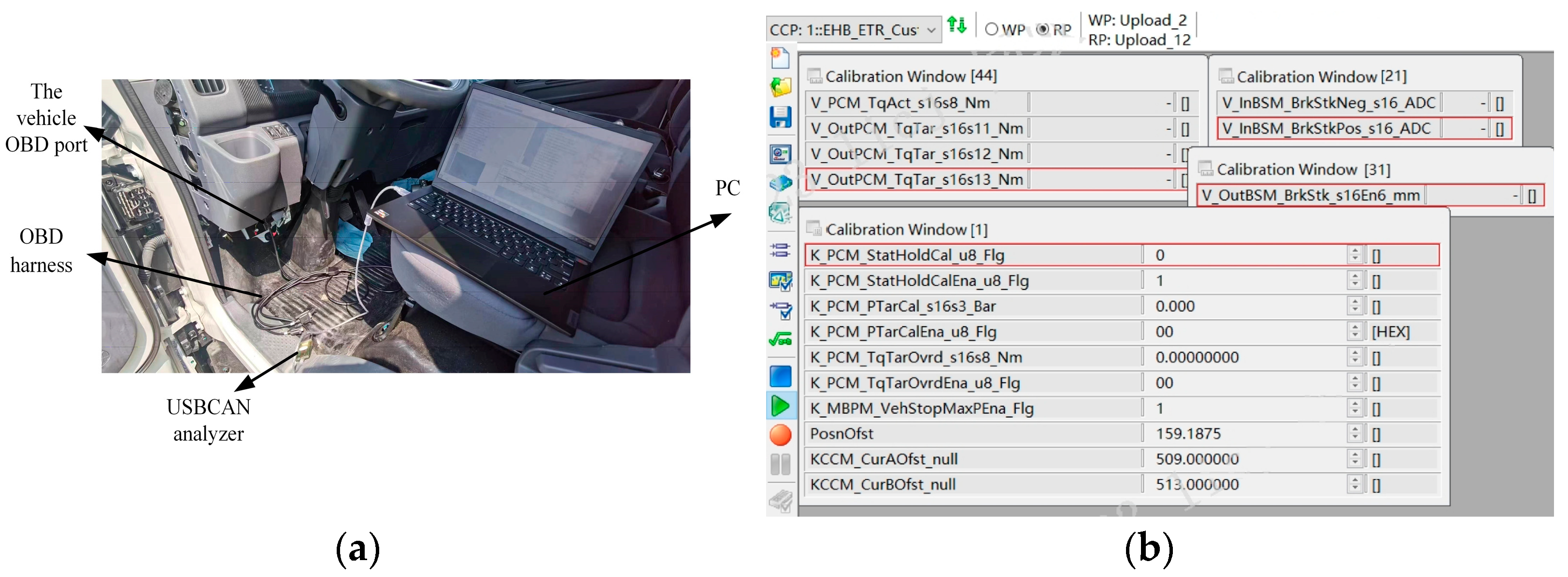
(1) The automotive OBD connection line (responsible for the CAN communication connection between the vehicle and the external controller).
(2) The USBCAN box analyzer (responsible for the configuration of the CAN communication signal forwarding and baud rate configuration).
(3) The PC (for calibrating parameters in the software, the opening or closing of the relevant function marker, and the recording and playback of the driving parameters).
The connection of each device in the experiment is shown in Figure 10a. After the connection of the experimental equipment, it is necessary to carry out real vehicle calibration of the software parameters through INCA. INCA can realize real-time monitoring of the internal data of the automobile braking system and realize different braking responses of the linear control dynamic system by changing the corresponding calibration parameters. The INCA interface is shown in Figure 10b.
The test vehicle of this paper is a miniature pure electric car owned by Chery. The specific parameters of the vehicle are shown in Table 1.
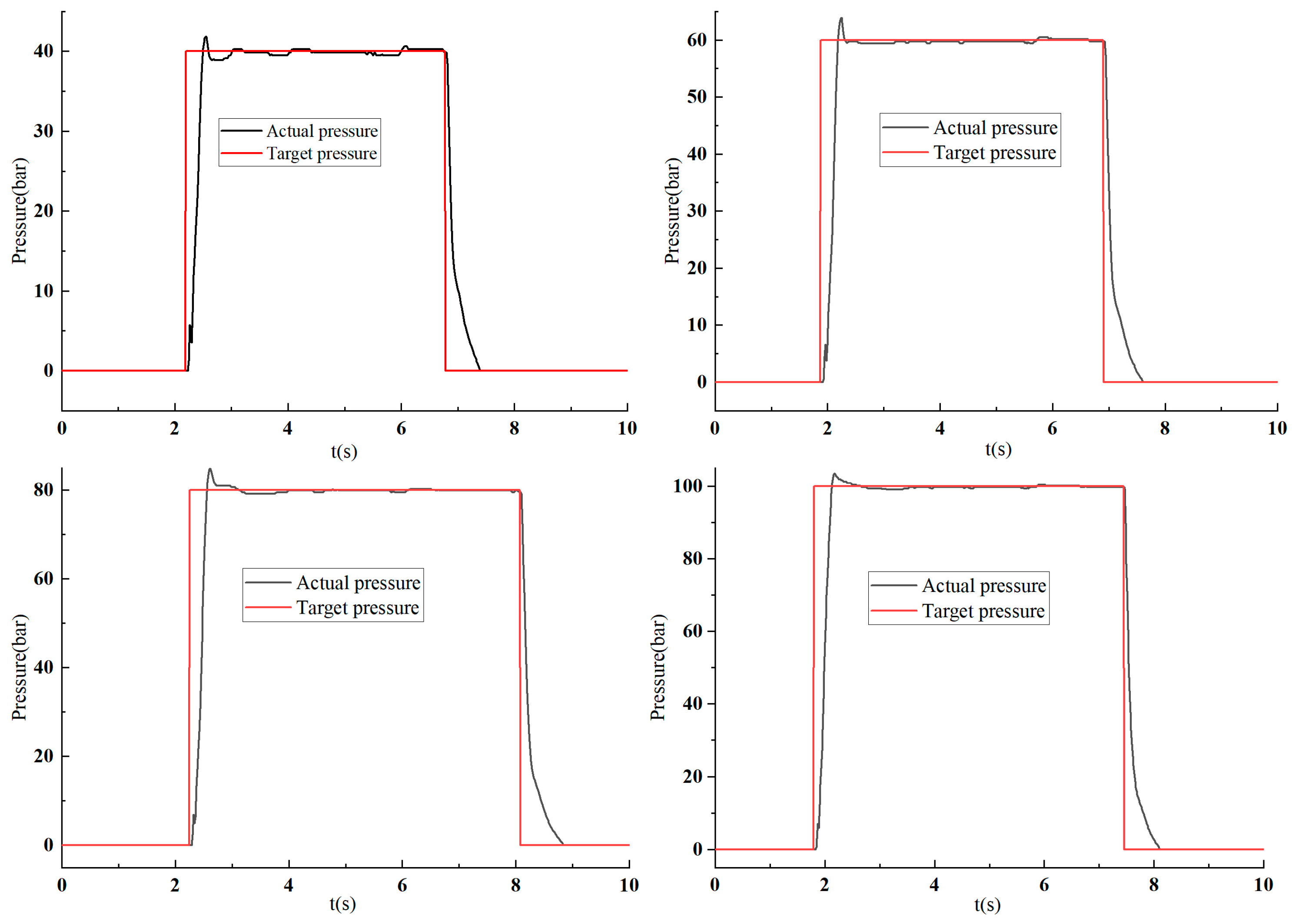
Before calibrating CST parameters, it is necessary to calibrate the essential braking response of the brake-by-wire system to the best condition to improve the braking performance of the vehicle. By sending step pressure-building commands through INCA, the pressure-building response of the brake-by-wire system with different target liquid pressure can be obtained. The liquid pressure response is shown in Figure 11.
According to the above data analysis, when the step target liquid pressure is 40 to 100 bar, the actual liquid pressure overshoot is kept within 10%, and the pressure-building time is 180 to 200 ms. The response data under each target value are shown in Table 2.

5.1. Real Vehicle Test of Slope Filtering

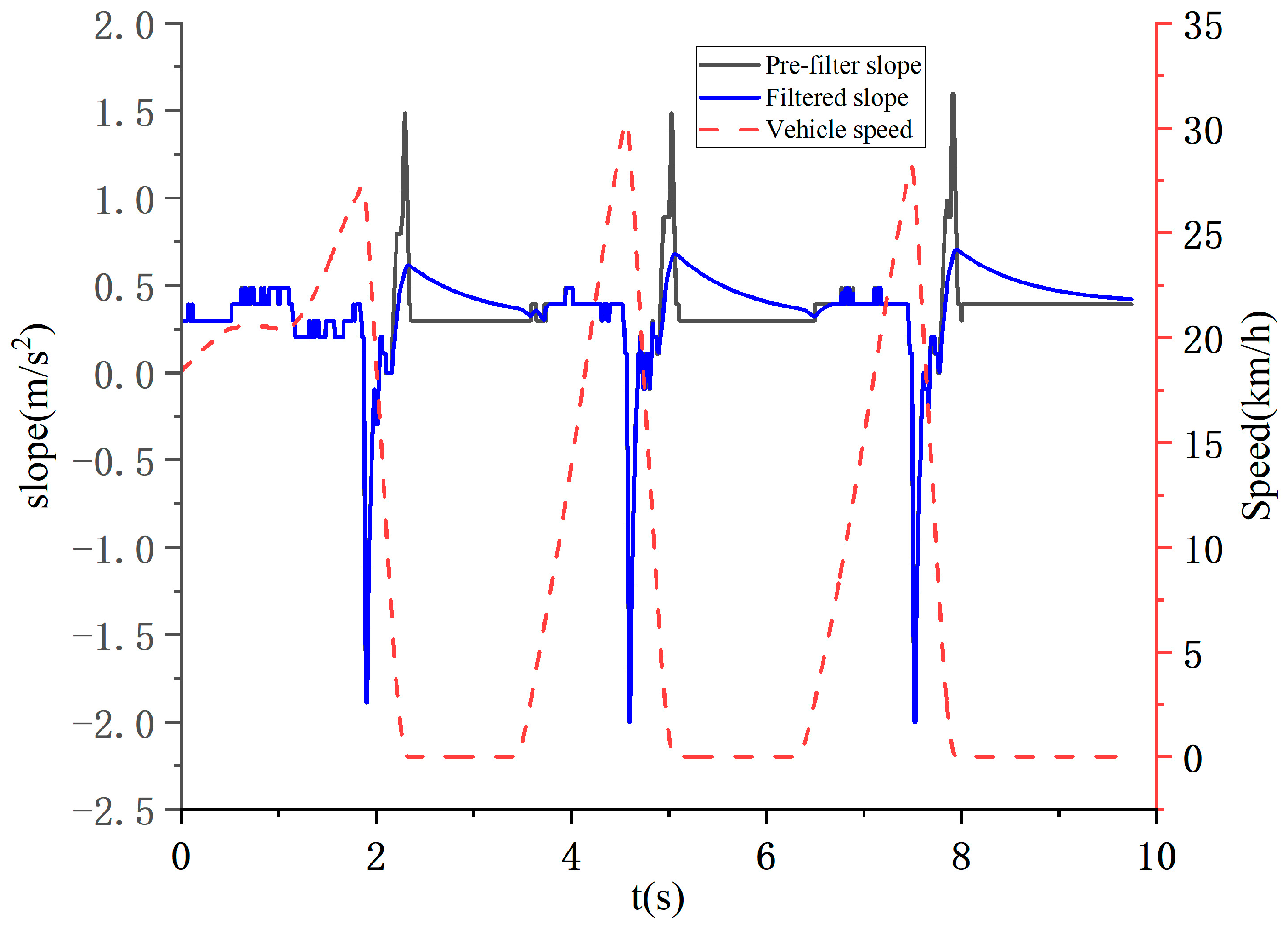
The slope data preprocessing module filters the slope data entered into the CST, enabling the judgment module to improve the data accuracy. In order to facilitate the construction of algorithmic models for the use of slope signals, in this paper, the slope signal is equivalently converted into gravity acceleration units. The slope signal will directly affect the minimum liquid pressure value of the vehicle in the process of pressure relief [28]. In this paper, the filtering coefficient is looked up according to the vehicle speed, and the theoretical design is as follows: as the speed increases, the gradient changes more greatly at the same time. According to the filtering model designed in this paper, the filtering coefficient needs to be increased through calibration to reduce the filtering intensity. The test results of the real vehicle are shown in Figure 12.
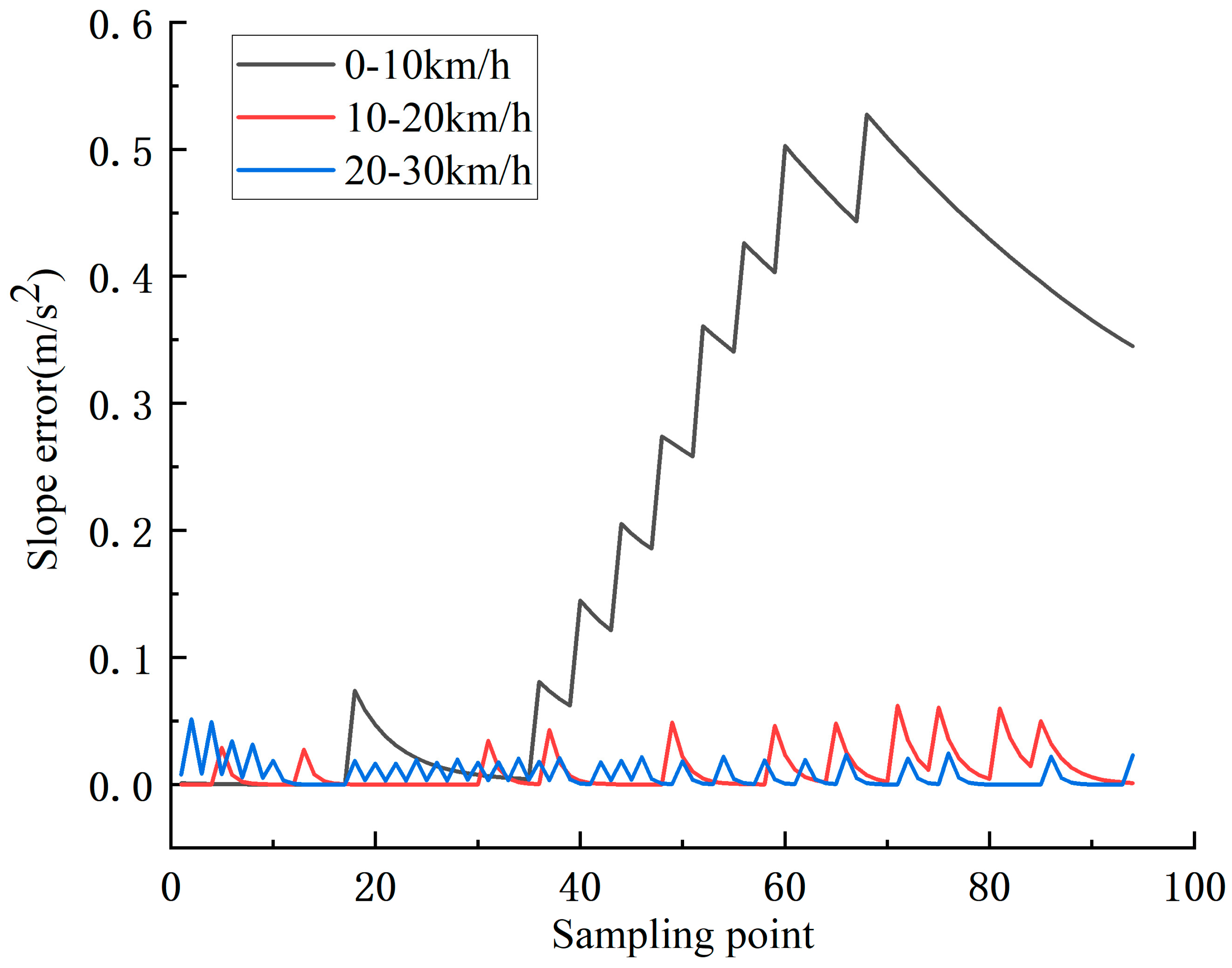
As can be seen from Figure 12, with the increase in vehicle speed, the filtering effect is weak even if the slope of the input filter module changes greatly. On the contrary, with the decrease in the speed, the change in the actual slope at the same time also decreases, and the filtering effect should be strengthened at this time. The slope-filtering algorithm designed in this paper can effectively pre-process slope signals. In order to further reflect the filtering effect, this paper extracted nearly 100 sampling points before and after slope filtering at the three-speed segments of 20–30 km/h, 10–20 km/h, and 0–10 km/h, respectively. It can be seen from Figure 13 that the filtering effect is strongest at the lower speed.

5.2. Motor Torque Response

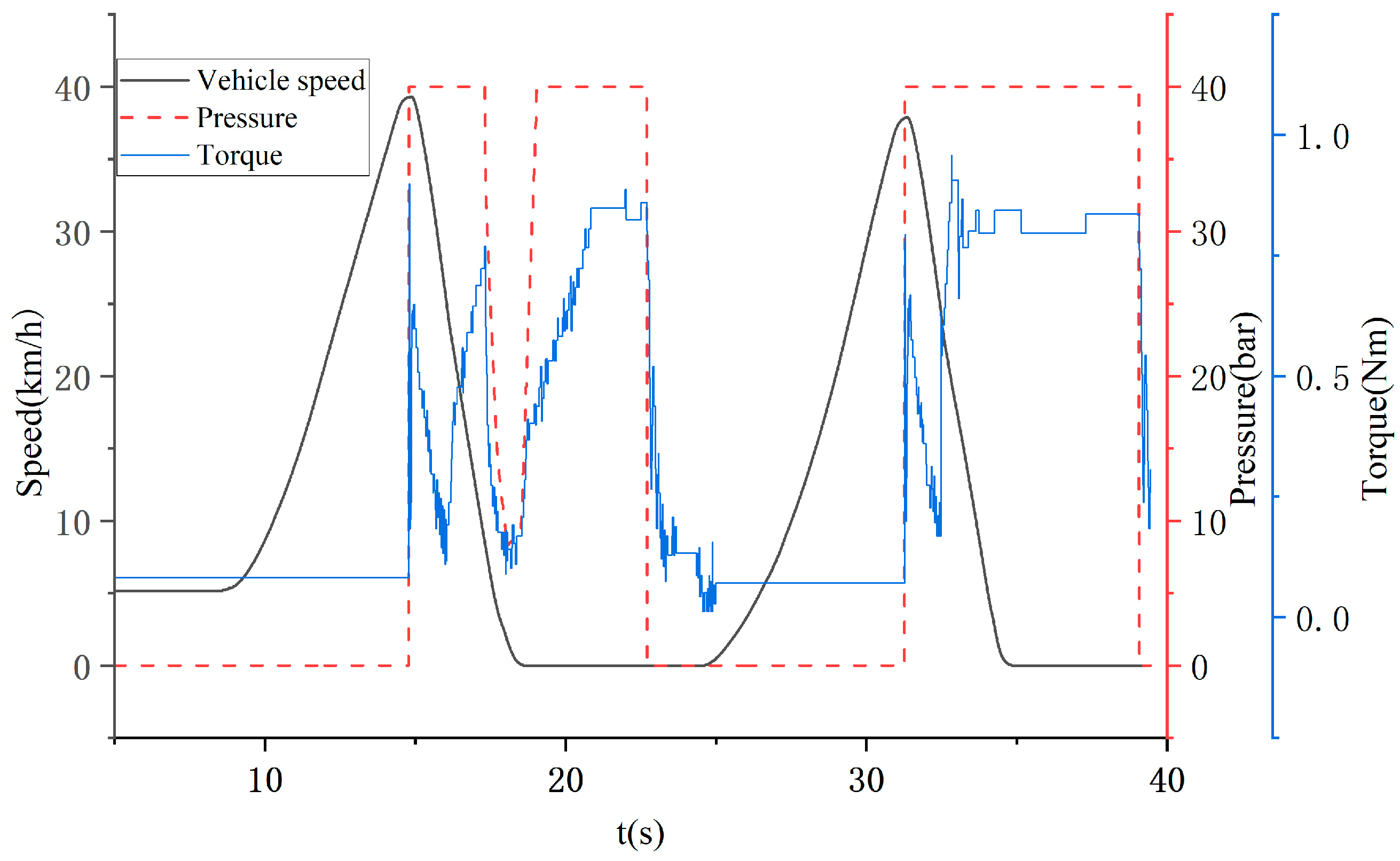
The brake-by-wire system differs from the traditional vacuum booster brake by motor help, so all the hydraulic pressure control algorithms in the controller will eventually be transformed into the control of the motor torque to determine the real-time change in the brake fluid pressure [29,30]. In order to compare the difference in the motor response under the normal state and CST activation state, the torque output under fluid pressure change under the two states was recorded through a real vehicle test, as shown in Figure 14.
In the real car test, the CST-enabled position is turned on and off, respectively, the vehicle is accelerated to 40 km/h, and the brake pedal is pressed at a constant speed. It can be seen from the data that when CST is activated, the motor torque decreases at the moment of pressure relief due to the target liquid pressure relief. Then, the motor torque begins to increase steadily to a fixed value, and the braking pressure is also maintained at the initial target braking pressure to ensure driving safety.

5.3. Brake Fluid Pressure Control

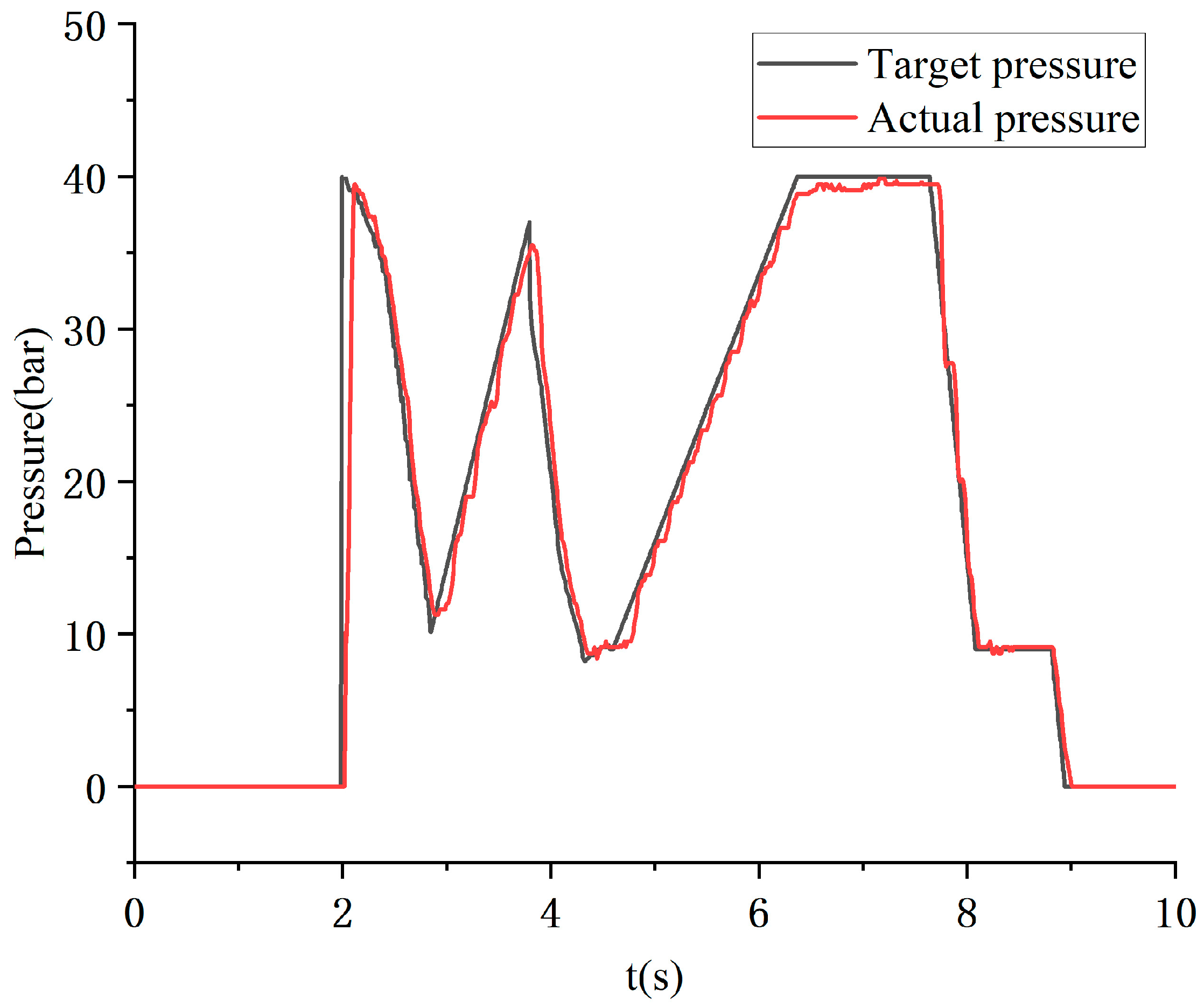
The anti-integral saturation PID control algorithm is used to control the hydraulic pressure of the brake-by-wire system [31] and the response time of the target 100 bar can be kept within 200 ms. Figure 15 shows the curves of the target and actual pressure in the liquid pressure control module when CST is activated.
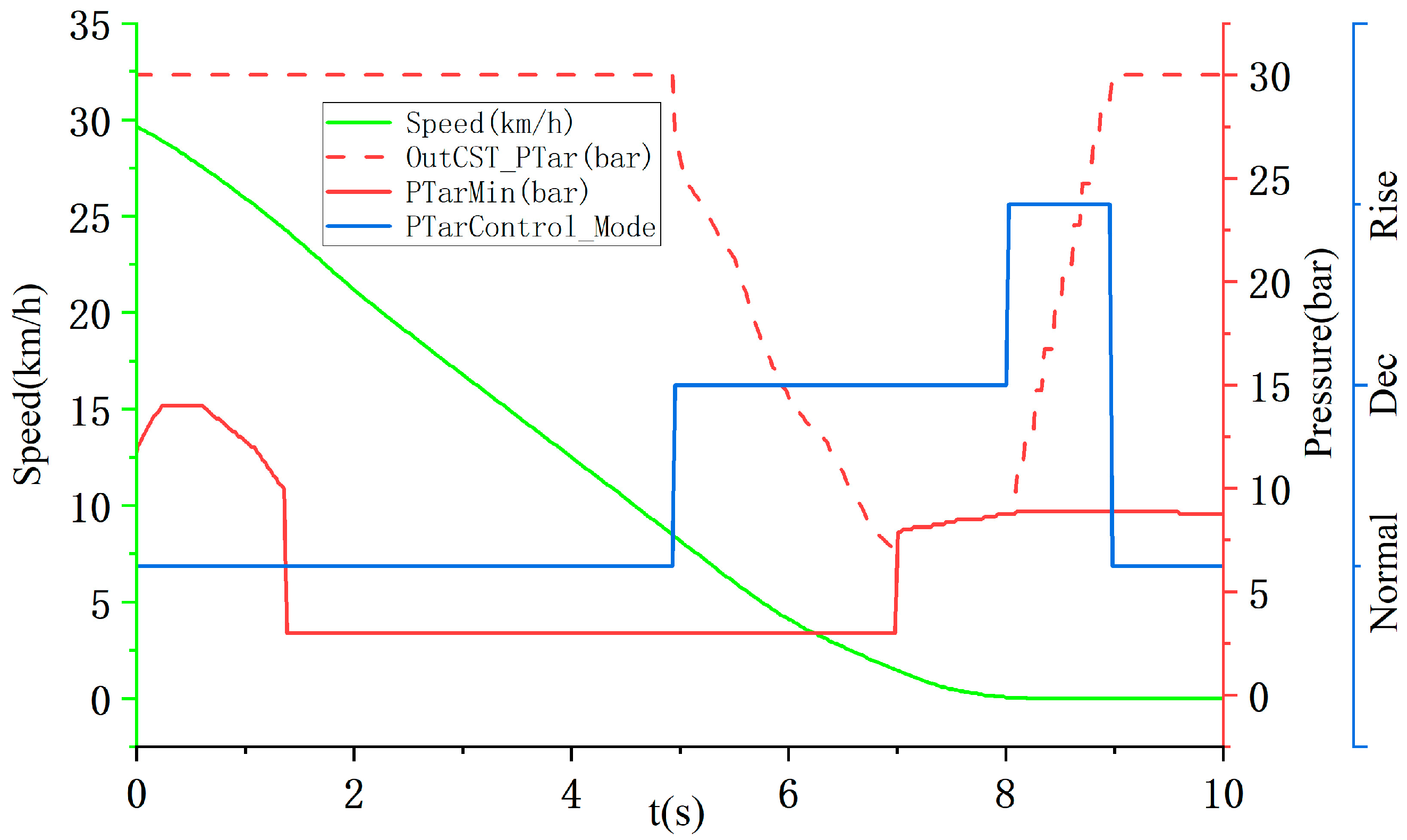
The vehicle can realize the braking stop without obvious nodding motion and ultimately depends on the brake fluid pressure control at the moment before stopping. In the test, the test vehicle will accelerate to 30 km/h, and then the driver starts to press the pedal to evenly slow down the vehicle to stop, so as to simulate the braking scene of normal travel and driving. The driving data recorded by the USBCAN analyzer is shown in Figure 16.
It can be seen from the test data that when the vehicle speed is 8 km/h, the CST liquid pressure control mode switches from Normal to Dec, the target liquid pressure output of CST starts to drop from 30 bar, and the final pressure relief value PTarMin is 7 bar. It can be seen from the previous calibration data that the standard quantity of minimum pressure relief value at this time is 3 bar. Since CST recognizes that the slope at this time exceeds the minimum slope threshold, the compensated pressure is 4 bar by checking the table of slope-compensation liquid pressure. When the control mode changes to Rise, CST’s output target liquid pressure rises and gradually increases to the initial target liquid pressure. In addition, from the perspective of subjective driving experience, this braking pressure control method can effectively improve the vehicle’s front and rear pitching.
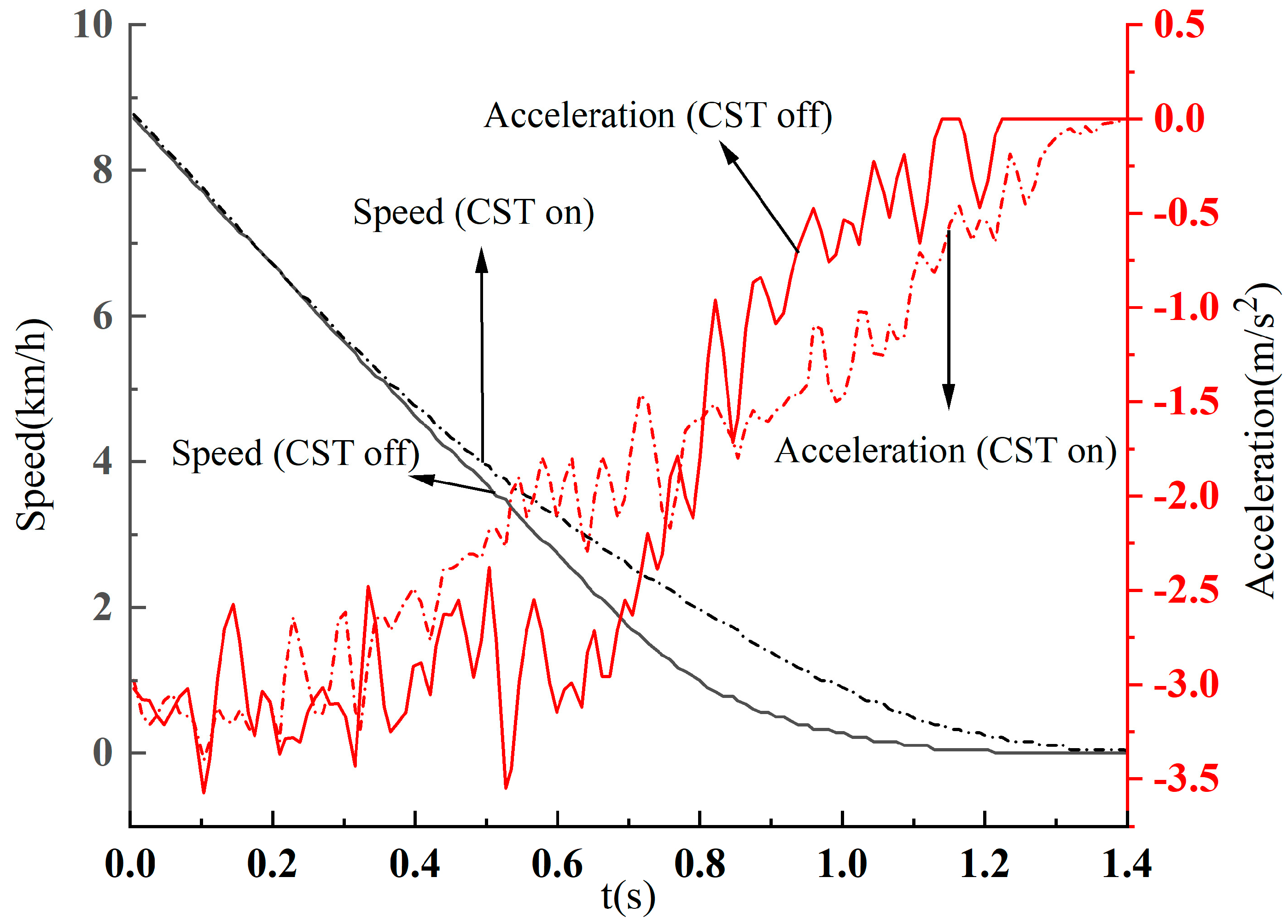
To further reflect the changes in the vehicle status after the CST function is turned on, we conducted the following tests under the same road conditions: the vehicle was accelerated to 30 km/h, and 30 bar liquid pressure was sent to the brake system until the vehicle stopped. From the subjective feelings of driving, it can be obviously felt that after opening CST, the vehicle can slow down to 0 more smoothly; when the CST function is not turned on, we will have a strong feeling of front and back pitching at the moment the vehicle stops. Then, record the driving speed data with the CST function on and off, as shown in Figure 17.
As can be seen from Figure 16, the CST function is activated when the vehicle speed is reduced to 8–9 km/h. Therefore, we show the speed change from the CST function activation to the vehicle stop in Figure 17. It can be seen that when the CST function is turned on, the slope of the overall speed drops more slowly, and the acceleration more gently approaches 0, thus providing a more comfortable feeling of longitudinal parking. Similarly, we can see that after the CST function is turned on, the stopping distance will become longer, but the CST function will only be activated at a lower speed, and when the speed drops to 0, the parking distance will become longer. The actual brake fluid pressure will immediately return to the initial target value to ensure sufficient braking force. Finally, we conducted integral processing on the speed curve in Figure 17, and the distance can be obtained. After CST is activated, the total advance from the stop of the vehicle is 1.119 m. After the CST function is turned off, the vehicle travels 0.986 m under the same conditions; that is, the intervention of the CST function will extend the braking distance of the vehicle by 0.133 m. After considering the results of service braking comfort, we consider that this extra braking distance is within the acceptable range.

6. Conclusions

This paper designs an algorithm that can reduce the pitch feeling in the moment before stopping. When the vehicle speed is about to become 0, the brake fluid pressure is quickly adjusted through the brake-by-wire system so that the deceleration of the car tends to be smooth to achieve the purpose of comfortable stopping, and the results of the research in this paper have a good reference significance for the active control of automobiles. The main content and innovation of this paper are as follows:
(1) The vehicle comfort braking algorithm model is built based on the brake-by-wire system, and the model C code is integrated into the total controller of the brake-by-wire system. In this way, the advantages of the hydraulic pressure response of the brake-by-wire system are that it is fast and easy to adjust, can be fully utilized, and the initial target pressure can be quickly maintained after the pressure relief is completed, which improves the braking comfort and ensures driving safety.
(2) The comfort braking algorithm designed in this paper can adjust the braking deceleration according to the feelings of different models and drivers. It can quickly generate embedded software and write it into the braking system by checking the table for calibration.

Author Contributions

Conceptualization, J.L. and T.Z.; methodology, J.L.; software, B.H.; validation, B.H.; formal analysis, Y.Z.; investigation, J.L.; resources, B.H.; writing—original draft preparation, J.L.; writing—review and editing, Y.Z.; visualization, B.H.; supervision, T.Z.; All authors have read and agreed to the published version of the manuscript.

Funding

This research was funded by the National Key R&D Program of China, grant number “2021YFA1500900”.

Data Availability Statement

Not applicable.

Conflicts of Interest

The authors declare no conflict of interest.

References

  1. Zhao, Y.; Zhang, C. Electronic Stability Control for Improving Stability for an Eight in-Wheel Motor-Independent Drive Electric Vehicle. Shock. Vib. 2019, 2019, 8585670. [Google Scholar] [CrossRef] [Green Version]
  2. Li, Y.; Deng, H.; Xu, X.; Wang, W. Modelling and testing of in-wheel motor drive intelligent electric vehicles based on co-simulation with Carsim/Simulink. IET Intell. Transp. Syst. 2019, 13, 115–123. [Google Scholar] [CrossRef]
  3. Hu, C.; Pan, G.; Kong, L.; Yu, J. Research of Brake by Wire System. J. Phys. Conf. Ser. 2023, 2479, 012051. [Google Scholar] [CrossRef]
  4. Li, D.; Tan, C.; Ge, W.; Cui, J.; Gu, C.; Chi, X. Review of Brake-by-Wire System and Control Technology. Actuators 2022, 11, 80. [Google Scholar] [CrossRef]
  5. Xiang, W.; Richardson, P.C.; Zhao, C.; Mohammad, S. Automobile Brake-by-Wire Control System Design and Analysis. IEEE Trans. Veh. Technol. 2008, 57, 138–145. [Google Scholar] [CrossRef]
  6. Meng, B.; Yang, F.; Liu, J.; Wang, Y. A Survey of Brake-by-Wire System for Intelligent Connected Electric Vehicles. IEEE Access 2020, 8, 225424–225436. [Google Scholar] [CrossRef]
  7. Ji, F.; Zhou, X.; Zhu, W. Pedal simulator and braking feel evaluation in brake by wire system. J. Beijing Univ. Aeronaut. Astronaut. 2015, 41, 989–994. [Google Scholar]
  8. Durali, L.; Khajepour, A.; Jeon, S. Design and optimization of a cam-actuated electrohydraulic brake system. Proc. Inst. Mech. Eng. J. Automob. Eng. 2018, 232, 909–920. [Google Scholar] [CrossRef]
  9. Ma, B.; Lin, M.; Chen, Y.; Wang, L.X. Investigation of energy efficiency for electro-hydraulic composite braking system which is based on the regenerated energy. Adv. Mech. Eng. 2016, 8, 1687814016666449. [Google Scholar] [CrossRef] [Green Version]
  10. Zhao, X.; Xu, B.W.; Gang, L. Pressure Estimation and Pressure Control of Hydraulic Control Unit in Electric-Wheel Vehicle. Math. Probl. Eng. 2020, 2020, 6576297. [Google Scholar]
  11. Seo, M.; Yoo, C.; Park, S.S.; Nam, K. Development of Wheel Pressure Control Algorithm for Electronic Stability Control (ESC) System of Commercial Trucks. Sensors 2018, 18, 2317. [Google Scholar] [CrossRef] [PubMed] [Green Version]
  12. Bao, H.; Li, G.; Du, S.; Liu, Y.; Yumei, L. Research on the Influence of Commercial Vehicle Electronic Control Pneumatic Braking Pressure Change Rate on Braking Ride Comfort. Integr. Ferroelectr. 2021, 217, 265–278. [Google Scholar] [CrossRef]
  13. Kosaki, S.; Ejiri, A.; Oya, M. Development of driver braking control model based on ride comfort index. Artif. Life Robot. 2021, 26, 347–353. [Google Scholar] [CrossRef]
  14. Zhaohui, W.; Yanfei, L.; Gang, P. A Smart Car Control Model for Brake Comfort Based on Car Following. IEEE Trans. Intell. Transp. Syst. 2009, 10, 42–46. [Google Scholar] [CrossRef]
  15. Jin, L.; Yu, Y.; Fu, Y. Study on the ride comfort of vehicles driven by in-wheel motors. Adv. Mech. Eng. 2016, 8, 1687814016633622. [Google Scholar] [CrossRef] [Green Version]
  16. Lingying, Z.; Min, Y.; Xinxin, X. Intelligent optimization of EV comfort based on a cooperative braking system. Proc. Inst. Mech. Eng. 2021, 235, 2904–2916. [Google Scholar]
  17. Zhang, J.; Sun, W.; Liu, Z.; Zeng, M. Comfort braking control for brake-by-wire vehicles. Mech. Syst. Signal Process. 2019, 133, 106255. [Google Scholar] [CrossRef]
  18. Huang, S.; Zhou, C.; Yang, L.; Qin, Y.; Huang, X.; Hu, B. Transient fault tolerant control for vehicle brake-by-wire systems. Reliab. Eng. Syst. Saf. 2016, 149, 148–163. [Google Scholar] [CrossRef]
  19. Gong, X.; Ge, W.; Yan, J.; Zhang, Y.; Gongye, X. Review on the Development, Control Method and Application Prospect of Brake-by-Wire Actuator. Actuators 2020, 9, 15. [Google Scholar] [CrossRef] [Green Version]
  20. Shuai, C.; Xilong, Z.; Jizhong, W. Sliding Mode Control of Vehicle Equipped with Brake-by-Wire System considering Braking Comfort. Shock. Vib. 2020, 2020, 5602917. [Google Scholar]
  21. Liu, X.; Song, J.; Yu, L.; Lu, Z.; Wang, J.; Abi, L. Study on ride comfort in post-braking phase based on brake-by-wire system. Proc. Inst. Mech. Eng. J. Automob. Eng. 2023, 237, 381–392. [Google Scholar] [CrossRef]
  22. Ribeiro, D.; Bragança, C.; Costa, C.; Jorge, P.; Silva, R.; Arêde, A.; Calçada, R. Calibration of the numerical model of a freight railway vehicle based on experimental modal parameters. Structures 2022, 38, 108–122. [Google Scholar] [CrossRef]
  23. Wu, W.; Kurachi, R.; Zeng, G.; Matsubara, Y.; Takada, H.; Li, R.; Li, K. IDH-CAN: A Hardware-Based ID Hopping CAN Mechanism With Enhanced Security for Automotive Real-Time Applications. IEEE Access 2018, 6, 54607–54623. [Google Scholar] [CrossRef]
  24. Chinchul, C.; Wootaik, L. Extended Digital Programmable Low-Pass Filter for Direct Noise Filtering of Three-Phase Variables in Low-Cost AC Drives. Energies 2022, 15, 2096. [Google Scholar]
  25. Han, W.; Xiong, L.; Yu, Z. Braking pressure control in electro-hydraulic brake system based on pressure estimation with nonlinearities and uncertainties. Mech. Syst. Signal Process. 2019, 131, 703–727. [Google Scholar] [CrossRef]
  26. Biaofei, S.; Lu, X.; Zhuoping, Y. Pressure Estimation of the Electro-Hydraulic Brake System Based on Signal Fusion. Actuators 2021, 10, 240. [Google Scholar]
  27. Peng, P.; Wang, H.; Pi, D.; Wang, E.; Yin, G. Two-layer mass-adaptive hill start assist control method for commercial vehicles. Proc. Inst. Mech. Eng. J. Automob. Eng. 2020, 234, 438–448. [Google Scholar] [CrossRef]
  28. Jin, L.; Zhang, R.; Tang, B.; Guo, H. A Fuzzy-PID Scheme for Low Speed Control of a Vehicle While Going on a Downhill Road. Energies 2020, 13, 2795. [Google Scholar] [CrossRef]
  29. Sun, Z.; Liu, C.; Li, M.; Zhao, J.; Xu, Y. Application of anti integral saturation cascade PID control algorithm in superheated steam temperature control. J. Phys. Conf. Ser. 2021, 2087, 012038. [Google Scholar] [CrossRef]
  30. Wang, C.; Zhao, W.; Li, W. Braking sense consistency strategy of electro-hydraulic composite braking system. Mech. Syst. Signal Process. 2018, 109, 196–219. [Google Scholar] [CrossRef]
  31. Chen, Q.; Shao, H.; Liu, Y.; Xiao, Y.; Wang, N.; Shu, Q. Hydraulic-pressure-following control of an electronic hydraulic brake system based on a fuzzy proportional and integral controller. Eng. Appl. Comput. Fluid Mech. 2020, 14, 1228–1236. [Google Scholar] [CrossRef]
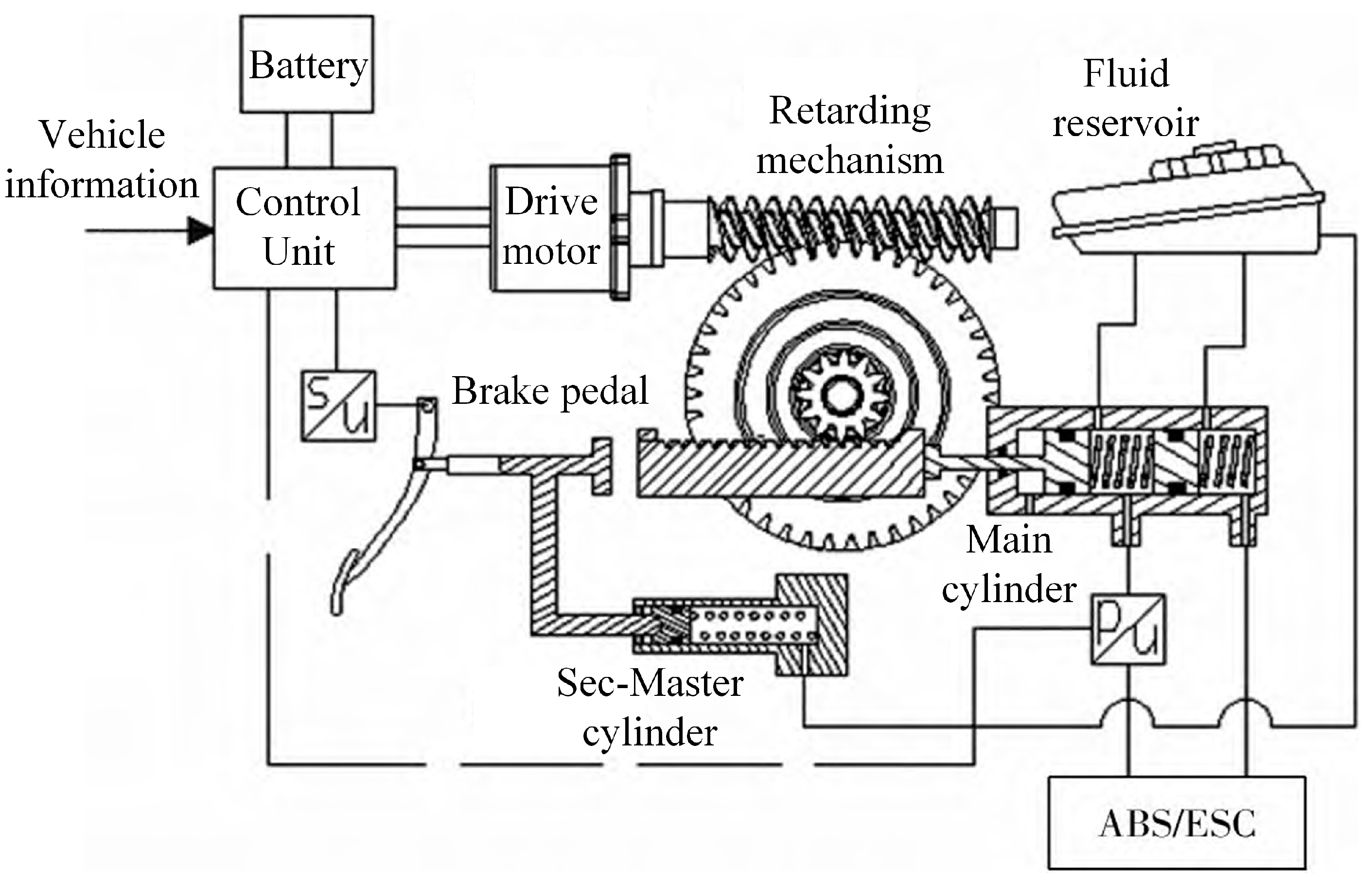
Figure 1. Brake-by wire system structure diagram.
Wevj 14 00220 g001
Figure 2. CST working principle diagram.
Wevj 14 00220 g002
Figure 3. CST software overall architecture.
Wevj 14 00220 g003
Figure 4. Flow chart of hydraulic pressure control algorithm.
Wevj 14 00220 g004
Figure 5. Slope signal filtering module.
Wevj 14 00220 g005
Figure 6. Filter module 1.
Wevj 14 00220 g006
Figure 7. Filter module 2.
Wevj 14 00220 g007
Figure 8. CST function status judgment.
Wevj 14 00220 g008
Figure 9. The jump logic of CST liquid pressure control state.
Wevj 14 00220 g009
Figure 10. Device connection and calibration interface. (a) The connection of each device in the experiment; (b) The INCA interface.
Wevj 14 00220 g010
Figure 11. Pressure response of each stage.
Wevj 14 00220 g011
Figure 12. Slope filtering and speed change map.
Wevj 14 00220 g012
Figure 13. Slope-filtering error at different speed segments.
Wevj 14 00220 g013
Figure 14. Motor torque response under normal and CST activation.
Wevj 14 00220 g014
Figure 15. Hydraulic pressure response.
Wevj 14 00220 g015
Figure 16. Signal response in each CST functional state.
Wevj 14 00220 g016
Figure 17. Speed and acceleration comparison with and without CST function.
Wevj 14 00220 g017
Table 1. Test vehicle parameters.
Parameter NameNumerical ValueParameter NameNumerical Value
G (vehicle quality)1015 kgTotal motor torque120 Nm
Wheelbase2160 mmR (tire radius)0.275 m
Front wheelbase1450 mmCentroid height0.56 m
Rear wheelbase1430 mmMoment of inertia 1470   kg · m 2
μ 0.4 d 1 ,   d 2 51.1 mm, 34 mm
r 1 ,   r 2 27 mm, 24 mm
Table 2. Step response of liquid pressure.
Target Fluid Pressure (bar)406080100
Actual maximum response value (bar)41.8863.8884.87103.50
Percentage overshoot4.70%6.47%6.09%3.50%
Response time (ms)181180180190
Disclaimer/Publisher’s Note: The statements, opinions and data contained in all publications are solely those of the individual author(s) and contributor(s) and not of MDPI and/or the editor(s). MDPI and/or the editor(s) disclaim responsibility for any injury to people or property resulting from any ideas, methods, instructions or products referred to in the content.