Abstract
The braking system is one of the most important components of a vehicle. In general, the brakes will generate heat due to the braking process. The heat generated must be released into the environment to maintain braking performance at optimal conditions. In extreme conditions, braking will fail. The braking system can be developed as a braking support system is a non-contact braking system. One form of the non-contact braking system is the eddy current brake (ECB). ECB is an electric braking system with the principle of eddy current. In the ECB, overheating will result in decreased performance. The approach that can be taken to determine braking performance during heat generation is the modeling process using FEM. This study uses FEM to analyze the heat generated during braking. In addition to using FEM, research was carried out using experiments as a comparison. Analysis of heat generation in braking is needed to determine whether braking with ECB can be a backup and its potential as a substitute for friction brakes. The results show that the ECB heat generation event that affects the temperature rise reduces the braking torque performance. Research indicates that when overheating occurs, braking performance will decrease by up to 10% when the disk surface temperature rises more than 20 °C. It shows the importance of managing heat that occurs in the ECB.
1. Introduction
Brakes are devices to slow down a moving vehicle. When the brakes are used, the kinetic and potential energy will be absorbed and converted into heat energy through friction [1]. The energy absorbed in the braking process must be released into the environment. Repeated use of the brakes causes the brake components to generate heat higher than their ability to dissipate heat. Excessive heat that occurs in the braking components will reduce brake performance. In addition, excessive heat in the braking system can reduce the life of the brake components. One way that can be done to increase the service life of brake components is to combine braking methods. The method commonly used is mechanical braking, supported by engine braking, to produce good braking and prolong the life of the braking components [2].
Previous research has shown the risk of failure in brakes; it is known that the disc brakes used can be damaged at certain times. In addition to the discs used, frequent breakdowns are commonly found in brake shoes [3]. Failure of the braking system will increase the risk of an accident in the vehicle. The selection of good braking system design and properties can reduce the risk of accidents [4]. One of the causes of brake damage is too heavy a load received by the brakes [5]. Some analyzes have been carried out regarding the causes of accidents; these studies always state that the failure of the braking system is one of the main factors [4,5,6,7,8,9].
The development of transportation technology has led to the use of electric and hybrid vehicles. The use of electric vehicles has better energy efficiency and is environmentally friendly. Electric vehicles have the disadvantage that there is no engine braking. One way that can be used as a substitute for engine braking on electric vehicles is to use regenerative braking. In addition to being used as braking support, regenerative brakes can generate electricity [10,11]. The electricity generated will then be stored in batteries for reuse, in addition to using regenerative braking. Table 1 provides an overview of the performance ratio of the existing braking system. Eddy current brake (ECB) has a better performance ratio than the active area, where the ECB has a value of 13.89 and a friction disc brake of 5.95 when used on a vehicle weighing 200 kg. The use of the ECB will be ideal as an alternative braking system because, in addition to having a large torque ratio, the ECB also has a fairly good temperature resistance. ECB is a braking system using the eddy current principle. Eddy current is an induced current formed in the conductor to produce a braking force. In general, the main components of the ECB consist of a magnetic field source and a conductor. In its development, ECB can be combined with regenerative braking to increase energy efficiency [12]. ECB applications are generally used to improve braking performance and reduce the risk of failure of the mechanical system. In addition, the use of ECB has the advantage that it can be used effectively at high speeds [13]. It is the reason that the ECB can be used in high-speed vehicles. Current developments also show the potential for its application in light vehicles such as cars and motorcycles [14,15]. An eddy current brake will be suitable for light vehicles such as motorcycles and cars with light weight. It is because most of the backup braking used on vehicles is combined with regenerative braking. On the other hand, regenerative braking will be suitable for vehicles with a fairly large weight because the braking performance will depend on the energy generated by the vehicle’s weight.

Table 1.
Comparison of braking system properties.
Few researchers have conducted scientific studies that summarize the development of eddy currents, especially in studying the analysis of heat generated by the braking process. Only a review journal discusses the ECB, Ananth [16], which generally discusses the ECB system. Singh, 2014 [17] conducted a journal review with the theme of ECB system design for various uses. Thompson, 2009 [18] conducted a journal review regarding the application of NdFeB permanent magnets in various system applications, one of which is ECB. Waloyo, 2019 [19] conducted a study on the development of the ECB design. There are several discussions put forward by the authors, including journals that discuss the effect of using rotor materials (Alumunium, Cu, or ferromagnetic metals) on braking torque [20], giving grooves on the surface of the rotor [21], adding permanent magnets to the stator to increase the magnetic field’s magnitude [22] adding a back iron structure to increase magnetic conductivity [23] or a ferrous metal construction coated with a non-ferrous metal [24], and a Halbach permanent magnet configuration on permanent magnet ECB [25,26,27,28]. Research on the heat in the ECB is still quite limited. The majority of research conducted is on linear and radial designs. Existing research mostly suspects that the magnetic part is the part that needs to be considered for heat generation. However, the results showed that the source of the magnetic field did not experience a significant influence, but the conductor part experienced an increase in heat [25,29]. This paper will explain the discussion about the heat generation process that occurs at the ECB. For example, how the temperature on the ECB surface disk affects the resulting braking performance and how when there is airflow during the braking process. With this discussion, it is hoped that it will help the development of the ECB to be applied and developed further.
2. Materials and Methods
2.1. Basic Theory
Eddy currents are induced currents that arise due to changes in the magnetic field in a conductor. Eddy currents can appear in a stationary conductor affected by a changing magnetic field or when an object moves across a fixed magnetic field. The magnitude of the magnetic field produced by the induced current is proportional to the magnitude of the induced current that forms the loop. Solid objects will produce a stronger magnetic field than sheets because the current that forms the loop is larger. A magnetic field that induces a material will form two loops of induced current. The two loops will produce different magnetic fields. The magnetic field’s beginning will produce an induced magnetic field in the direction of the main magnetic field so that there is a repulsion between the two. While in the end, it will produce a magnetic field that attracts the main magnetic field and make a braking force. The two forces formed will produce a force opposite to the direction of the magnetic field movement. Smythe, 1942 [30], was the first researcher to study eddy currents on a disk.
The skin effect strongly influences the calculation of braking torque on the ECB. Where with increasing speed, the effect of skin effect increases. Sharif, 2009 [31] explained that the skin effect variable must be added to the calculation of braking torque. Sharif, 2012 [32] reviewed the ECB’s performance on the braking application. The skin effect has a different effect on the thickness of the conductor. Schieber, 1972 [33] conducted a study on ECB on thin plates and found that the effect of the skin effect was not too significant. Singh, 1977 [34] conducted a study on thick plates and looked at the effect on the skin effect. In thick conductors, the skin effect significantly affects the braking torque produced at high speeds.
The main magnetic field on the ECB is the source of energy used in operation. The magnetic field can be generated from a permanent magnet or using a coil that is energized. The magnetic field produced by a permanent magnet is constant over time. The braking torque can be controlled by adjusting the air gap or providing a magnetic field barrier. An electric coil generates the magnetic field. The magnetic flux the winding produces depends on the amount of electric current that flows. The amount of torque is regulated by changing the amount of current flowing. The greater the electric power provided, the greater the magnetic field produced. Setting the frequency and shape of the current signal also affects the performance. Using AC power will increase the braking torque [35]. Setting the speed and torque on the variation of the signal step sine and square [36,37]. Difficulty setting at low speed. Circuits can be made in parallel and series. By adjusting the circuit, the required performance is obtained [20,38]. Another application of eddy current brake combines a power generation unit or generator and a braking unit in one unit. There is a generator and eddy current brake in the existing components simultaneously. The resulting braking force can be multiplied simultaneously using the generator and braking system. To be used properly, the electric current generated by the generator is first processed by the control unit. By using the settings, the amount of braking torque provided by the unit can also be adjusted. Using ECB becomes a burden because it requires a lot of electrical energy. To reduce this, using its energy generators can overcome this [39,40,41,42].
ECB is a braking method that does not require physical contact in the braking process. ECB works by arranging a magnetic flux source, such as a permanent magnet or an electromagnet with a conducting disc connected to a rotating machine [43]. The braking torque of the ECB can also be calculated quite accurately in the low and high-speed ranges. The electromagnetic field influences the resulting braking torque. The following equation can determine the braking torque.
Equation (1) shows that disc thickness (), angular velocity (), electromagnetic radius (r), axis distance with ECB placement (m), flux density (), and radius (a) will affect the performance of the ECB [44,45,46]. The ECB operates by utilizing the eddy currents generated by magnetic induction. The ECB’s magnetic field source can come from a permanent magnet or an electric current. The magnetic field density is calculated from the magnetic field flux in each unit area. The resistivity or electrical conductivity of a material is a characteristic property of a material. The electrical resistance of a material is highly dependent on the temperature of the material. The resistivity of the material (σ) can be calculated by Equation (2).
where resistivities at zero degrees Celsius and change in conductivity per Celcius (). The formula to calculate the eddy current in Equation (2) only applies to thin disks. The induced current density depends on the magnitude of the main magnetic field that passes through the conductor. Another influential factor is the influence of the frequency of changes in the magnetic field on the conductor’s surface. The high frequency of changes in the magnetic field will cause a skin effect [47].
The skin effect will affect the torque generated after exceeding the critical speed. After going through the critical speed, there will be a decrease in braking torque. The skin effect is the concentration of electrons on the skin surface of a conductor due to the high frequency of changes in electrical polarity. The high frequency increases the effect of the skin effect so that the eddy current that is formed is only on the surface. The effect of heat generated from the ECB can be analyzed using several calculations and considerations. The first step that needs to be done is to analyze the air gap resistance (Rg) and the material (R) used.
where l is the length of the reluctant, s is the area of the reluctant and permeability. When the ECB is used for a long time, the temperature of the stator will increase. The value of magnetic permeability and electrical conductivity will decrease with increasing temperature. The value of the permeability decreases will increase the surface resistance of the conductor plate. An increase in the conductivity value will improve braking performance due to an increase in the eddy current density. In the process, when the conductivity value continues to increase, it will decrease torque due to the skin effect.
2.2. Research Process
The research process was carried out using the finite element method (FEM) to approach the simulation process. The simulation begins with determining the design of the unipolar axial ECB used and determining the pattern of heat generated. The simulation process is compared with the experimental process to compare research results. In the process, in addition to being used, as a result of validation, the experimental process aims to obtain initial heat generation data that will be included in the simulation properties. Several parameters of the simulation process can be seen in Table 2.
Table 2.
Properties of the simulation process carried out.
The simulation is carried out to observe the heat distribution process on the surface of the conductor plate used in the ECB, which is then carried out by analyzing the characteristics of the heat while driving. In the process, it is assumed that the disc’s rotational speed is constant but has different airflow speeds, namely 10, 20, 40, 60, and 80 km/h for each test. The airflow speed is a forced cooling process during the braking process. The ECB design and domain used can be seen in Figure 1. The modeling is done using Ansys electronics software to analyze the performance of the ECB, and Ansys is fluent in analyzing the heat phenomenon that occurs.

Figure 1.
ECB design used in the modeling process.
In addition to carrying out the simulation process, the experimental process is carried out to obtain verification data as a comparison of the simulation process that has been carried out. The experimental process carried out is to use a design, as shown in Figure 2.

Figure 2.
ECB experimental design carried out: (a) experimental test scheme, (b) test equipment used.
3. Results and Discussion
A strong magnetic field will affect braking performance. In addition to the strength of the magnetic field, the use of conductor material properties will affect braking performance. When the surface temperature of the conductor material is changed, the braking performance will also change. Using modeling will facilitate knowing the effect of temperature during the braking process by defining heat during the braking process. The analysis process uses the finite element method and Maxwell analysis. This study aims to analyze heat generation in the ECB braking process. The analysis process is carried out using the finite element method using the model in Figure 3a. The modeling process begins by using the analysis of heat generation carried out on the active region on the surface of the rotor disk used. Figure 3b shows the active region, which is an area that experiences a particular magnetic field effect.

Figure 3.
Eddy current brake: (a). domain on FEM, (b). Active region position.
3.1. Heat Generation That Occurs in the ECB
The temperature on the ECB increases with braking time. The temperature is relatively high in the winding and active areas. It is expected because the winding part is forced to flow to produce a magnetic field. At the same time, the active region is a component induced by eddy currents that produce braking force. Figure 4 shows the characteristics of the ECB heat increase that occurs during the braking process. When braking is applied and receives airflow, heat is released. It results in relatively less heat generation after 15 s. At the beginning of the braking process, the temperature rise is relatively high because of the forced current flow that activates the electromagnet. After that, the heat generation occurs within 15–45 s, and the heat generated is still at the level of the heat release capability of the components used. A slowly rising heat indicates this. After 45 s, the heat begins not to be released into the environment, so it will increase the temperature.

Figure 4.
Heat generation process on braking.
At the same time, the event of heat generation in the functional or active area can be seen in Figure 5. The area produces a higher temperature than the heat generated in Figure 4. The data taken is the active area on the disc brake and coil section. These results were obtained through a simulation process compared with the experiment. In this case, the coil generates heat up to 77 °C for the experimental data, while the simulation data shows no different results, namely 75 °C. The heat that arises in the disc brake comes from the coil. It causes the disc brake in the active area to have a higher temperature than the side area. The temperature generated by the active disc brake area reached 57 °C during the experiment and 52 °C using simulation.
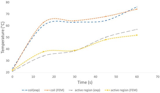
Figure 5.
Heat generation process on braking in active region and coil.
The simulation process is based on experimental data from heat generation on braking. The comparison between the experiment and the simulation results shows that the difference is not more than 10%, as shown in Table 3.
Table 3.
Error simulation and experiment.
The results showed that the braking process experienced a decrease in performance when the temperature was increased. When the temperature increases, the electrical conductivity value will decrease, which decreases braking performance. These phenomena correspond to what happened in Figure 6. Figure 6 shows a decrease in performance as the working temperature increases. At Equations (1)–(3), it is known that an increase in temperature results in a decrease in the conductivity of the conductor material used. The induced current’s value will decrease with a decrease in conductivity. The decreased induced current will result in a decrease in braking torque. Performance degradation coincides with temperature increases. In Figure 6, each change will generally decrease braking performance by up to 10% when increased by 5 Celsius. The decrease in temperature has the same characteristics as every increase in temperature. In addition to using experiments and simulations, mathematical methods are also used to strengthen the research conducted. Calculations were carried out using Equations (2) and (3), which were then substituted in Equation (1). The results obtained in experimental models, simulations, and mathematical calculations had the same trend. However, the experimental process showed slightly different results at a temperature of 35–40 °C. This phenomenon occurs due to the non-ideality of the testing process carried out. Of course, in this case, unexpected disturbances arise, so there is a difference in the temperature. However, the overall results show a slight difference or a small error.
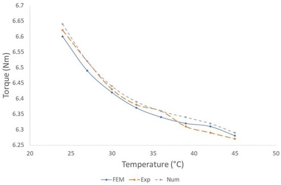
Figure 6.
Decreased braking torque when there is an increase in temperature to the ECB using a plain conductor disc.
The simulation process shows that the braking temperature is one of the critical factors that must be considered. It is understood that the generation of heat that occurs is expected during the energy conversion process. Using the heat generation analysis on the ECB, the optimal temperature will be obtained when the braking process is needed. The conductivity of the conductor material used also plays a high role. By looking at the phenomena that occur in Figure 4 and Figure 5, it is known that it is necessary to analyze the temperature regulation when implementing the ECB. Along with the ability to generate heat, in the future, it is necessary to increase the ability to release heat in the application of ECB.
3.2. ECB Heat Distribution Character
The braking process that takes place shows that when the hot braking process occurs, it tends to be dominant in the active area of the region. Several causes can cause this. For example, heat generated at the core winding or that occurs due to the emergence of eddy currents on the disc’s surface will spread to the inside and the edges of the disc used. Figure 7a shows that when the ECB is only turned on, the heat will tend to spread to the outside area. At the same time, Figure 7b shows the distribution of heat when the disc rotates. It follows the experiments carried out. In the experiments, the characteristics of the heat that arise are the same as those in the simulation process. Figure 8 shows a section of the visible area of the experimental process.

Figure 7.
Distribution of heat generated on the surface of the ECB disc: (a) Disc is at rest when the ECB is active, (b) Disc rotates when in use.

Figure 8.
Distribution of heat generated on the surface of the ECB disc: (a) Experiment, (b) Modeling.
When ECB is applied to a 2-wheeled electric vehicle, there will be a heat release caused by the airflow process that occurs during the driving process. It can be used as one of the considerations in designing the ECB. Figure 9 shows the heat release process during braking at various speeds. Based on Figure 9, the heat release that occurs at higher speeds shows the results of a smaller heat release area with a high concentration. Sequentially, the speeds applied in Figure 9a–d are 80 km/h, 60 km/h, 40 km/h, and 20 km/h. At a speed of 80 km/h, the heat release that occurs is seen to have more concentration in an area equal to the diameter of the disc used, while at other speeds, it tends to spread larger than the diameter of the disc. The process is carried out by adding air properties at a predetermined and equalized speed to make the heat release more visible. It is also done with the hope of equating the actual conditions at the time of its application. Data on the heat release results can be seen based on the decrease in temperature, as shown in Figure 10. Figure 10 shows a graph of the decrease in temperature either by simulation or experimental processes. The decrease in temperature with both processes shows the same trend with minor differences for each point of acquisition of the results. The initial temperature obtained at a speed of 10 km/h shows a temperature value of 79˚C. When the speed is increased gradually, the temperature decreases significantly until it reaches 47˚C at a speed of 80 km/h. The part that experiences heat generation is the part that is in the active region area. It is an appropriate trend because the active region absorbs energy to be converted into heat in the ongoing germination process [29,30].
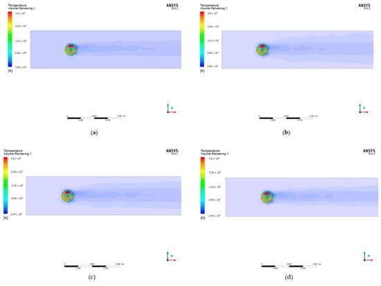
Figure 9.
The process of releasing heat that occurs at the speed of: (a) 80 km/h, (b) 60 km/h, (c) 40 km/h and (d) 20 km/h.

Figure 10.
Decrease in temperature when used to drive at various speeds.
4. Conclusions
The use of ECB in light vehicles needs to be adjusted according to need and consider safety aspects. One part that needs to be considered is the potential heat generated and how it affects the braking torque generated by the ECB. In general, heat is a natural phenomenon that occurs in the energy conversion process. In braking using the ECB, it is known that heat does affect braking torque. The modeling process shows that the hotter the ECB disc, the lower the braking performance, as seen from the torque value. The modeling process is carried out using FEM-based simulations and experimental processes. In addition, mathematical calculations are used to strengthen the results on one of the processed data. The results show that the ECB’s heat generation event that affects the temperature increase reduces the braking torque performance. Based on the experimental value, when the temperature is 25˚C, the braking torque is 6.63 Nm. This value decreased by 0.40 Nm to 6.23 Nm at 45˚C. It follows the actual situation because when it is hot, there will be a change in the properties of the conductor material used. However, with changes in light use, heat can still be released due to the speed of the vehicle moving. Therefore, when usage has been increased, it would be better if the ECB could be added with a cooling system, such as increasing the contact area with additional slots. In addition to the performance seen from the torque value, the research that has been carried out also provides prediction simulation results and thermal photos of the active area on the disc brake. The results show that the heat concentration in both the simulation and experimental processes is higher in the active area and closer to the center of the coil area.
Meanwhile, the phenomenon of heat release that occurs, which is reviewed based on the difference in speed, shows that the higher the concentration of heat release, the better and does not spread over a wider area compared with the lower speed. The heat on the surface of the ECB conductor influences the braking performance. The heat on the surface of the disc of the conductor used needs to be maintained to obtain stable performance at low and high speeds. It is sufficient to describe the process of heat generation in the axial type. In contrast, if we look at the heat generation in the ECB with other types, it has similar characteristics. The phenomenon of heat generation on the disc surface of the axial ECB conductor has never been described before. In the future, it is necessary to add a cooling system on the surface of the ECB axial disc. One thing that can be improved is to add grooving to the surface of the disk used.
Author Contributions
B.W.L., M.R.A.P. and M.N; methodology, D.D.D.P.T. and Z.A.; validation, M.N. and D.D.D.P.T.; investigation, B.W.L. and M.R.A.P.; writing—original draft preparation, M.R.A.P.; writing—review and editing, B.W.L.; visualization, I.I. and Z.A.; supervision, M.N. and D.D.D.P.T.; funding acquisition, M.N. All authors have read and agreed to the published version of the manuscript.
Funding
This research was funded by the ministry of education, culture, research and technology, no 018/E5/PG.02.00/2022 with contract no 054/E5/PG.02.00.PT/2022 and 469.1/UN27.22/PT.01.03/2022.
Data Availability Statement
Not applicable.
Conflicts of Interest
The authors declare no conflict of interest.
References
- Sawczuk, W.; Merkisz-Guranowska, A.; Ulbrich, D.; Kowalczyk, J.; Cañás, A.-M.R. Investigation and Modelling of the Weight Wear of Friction Pads of a Railway Disc Brake. Materials 2022, 15, 6312. [Google Scholar] [CrossRef] [PubMed]
- Zou, N.; Wang, Q.; Wang, W.; Zeng, X. Simulation Study of CVT Ratio Control for Engine Braking. In Proceedings of the 2009 International Conference on Measuring Technology and Mechatronics Automation, Zhangjiajie, China, 11–12 April 2009; pp. 367–370. [Google Scholar] [CrossRef]
- Putra, M.R.A.; Tjahjana, D.D.D.P. Fractures on braking component and relations to land-based transportation accident. Procedia Struct. Integr. 2020, 27, 147–154. [Google Scholar] [CrossRef]
- Pawar, N.M.; Khanuja, R.K.; Choudhary, P.; Velaga, N.R. Modelling braking behaviour and accident probability of drivers under increasing time pressure conditions. Accid. Anal. Prev. 2020, 136, 105401. [Google Scholar] [CrossRef] [PubMed]
- Popescu, F.D.; Radu, S.M.; Andraș, A.; Brînaș, I.; Budilică, D.I.; Popescu, V. Comparative Analysis of Mine Shaft Hoisting Systems’ Brake Temperature Using Finite Element Analysis (FEA). Materials 2022, 15, 3363. [Google Scholar] [CrossRef] [PubMed]
- Andras, A.; Brînaș, I.; Radu, S.M.; Popescu, F.D.; Popescu, V.; Budilică, D.I. Investigation of the Thermal Behaviour for the Disc-Pad Assembly of a Mine Hoist Brake Using COMSOL Multiphysics. Acta Tech. Napoc.-Ser. Appl. Math. Mech. Eng. 2021, 64, 227–234. [Google Scholar]
- Kamla, J.; Parry, T.; Dawson, A. Analysing truck harsh braking incidents to study roundabout accident risk. Accid. Anal. Prev. 2019, 122, 365–377. [Google Scholar] [CrossRef]
- Rainey, D.; Parenteau, M.A.; Kales, S.N. Sleep and Transportation Safety: Role of the Employer. Sleep Med. Clin. 2019, 14, 499–508. [Google Scholar] [CrossRef]
- Ghaleh, S.; Omidvari, M.; Nassiri, P.; Momeni, M.; Mohammadreza Miri Lavasani, S. Pattern of safety risk assessment in road fleet transportation of hazardous materials (oil materials). Saf. Sci. 2019, 116, 1–12. [Google Scholar] [CrossRef]
- Luo, N.; Jiang, J.; Yu, A. Research on the control strategy of the regenerative braking system. In Proceedings of the 2014 International Conference on Mechatronics and Control (ICMC), Jinzhou, China, 3–5 July 2014; pp. 2514–2517. [Google Scholar] [CrossRef]
- Kim, J.S.; Kim, S.M.; Jeong, J.H.; Jeong, S.C. Effect of regenerative braking energy on battery current balance in a parallel hybrid gasoline-electric vehicle under FTP-75 driving mode. Int. J. Automot. Technol. 2016, 17, 865–872. [Google Scholar] [CrossRef]
- Yazdanpanah, R.; Mirsalim, M. Hybrid Electromagnetic Brakes: Design and Performance Evaluation. IEEE Trans. Energy Convers. 2015, 30, 60–69. [Google Scholar] [CrossRef]
- Jee, I.H.; Nahm, S.Y.; Kang, S.J.; Ryu, K.-S. A Magnetic Brake for Small Wind Turbines. J. Magn. 2012, 17, 33–35. [Google Scholar] [CrossRef]
- Singh, A.K.; Ibraheem. Model Development of Eddy Current Brakes for Energy Absorbing System. In Proceedings of the 2015 International Conference on Recent Developments in Control, Automation and Power Engineering (RDCAPE), Noida, India, 12–13 March 2015. [Google Scholar]
- Luo, L.; Zhai, Q.; Li, W.; Qian, C.; Liu, H. Research on an integrated electromagnetic auxiliary disc brake device for motor vehicle. IEEJ Trans. Electr. Electron. Eng. 2017, 12, 434–439. [Google Scholar] [CrossRef]
- Anantha Krishna, G.L.; Sathish Kumar, K.M. Investigation on Eddy Current Braking Systems—A Review. Appl. Mech. Mater. 2014, 592, 1089–1093. [Google Scholar] [CrossRef]
- Singh, A.K.; Ibraheem; Sharma, A.K. Parameter identification of eddy current braking sytem for various applications. In Proceedings of the 2014 Innovative Applications of Computational Intelligence on Power, Energy and Controls with Their Impact on Humanity (CIPECH), Ghaziabad, India, 28–29 November 2014; pp. 191–195. [Google Scholar] [CrossRef]
- Thompson, M.T. Practical Issues in theUse of NdFeB Permanent Magnets in Maglev, Motors, Bearings, and Eddy Current Brakes. Proc. IEEE 2009, 97, 1758–1767. [Google Scholar] [CrossRef]
- Waloyo, H.; Ubaidillah, U.; Tjahjana, D.D.D.P.; Nizam, M.; Koga, T. Mini review on the design of axial type eddy current braking technology. Int. J. Power Electron. Drive Syst. 2019, 10, 2198. [Google Scholar] [CrossRef]
- Gulec, M.; Yolacan, E.; Aydin, M. Design, analysis and real time dynamic torque control of single-rotor–single-stator axial flux eddy current brake. IET Electr. Power Appl. 2016, 10, 869–876. [Google Scholar] [CrossRef]
- Garbiec, T.; Kowol, M.; Kołodziej, J. Design considerations of high-speed eddy-current brake. Arch. Electr. Eng. 2014, 63, 295–304. [Google Scholar] [CrossRef]
- Yazdanpanah, R.; Mirsalim, M. Analytical study of axial-flux hybrid excitation eddy current brakes. Int. J. Appl. Electromagn. Mech. 2015, 47, 885–896. [Google Scholar] [CrossRef]
- Sinmaz, A.; Gulbahce, M.O.; Kocabas, D.A. Design and finite element analysis of a radial-flux salient-pole eddy current brake. In Proceedings of the 2015 9th International Conference on Electrical and Electronics Engineering (ELECO), Bursa, Turkey, 26–28 November 2015; pp. 590–594. [Google Scholar] [CrossRef]
- Cho, S.; Liu, H.; Ahn, H.W.; Lee, J.; Lee, H.-W. Eddy Current Brake with a Two-Layer Structure: Calculation and Characterization of Braking Performance. IEEE Trans. Magn. 2017, 53, 5. [Google Scholar] [CrossRef]
- Jin, Y.; Kou, B.; Zhang, L.; Zhang, H.; Zhang, H. Magnetic and Thermal Analysis of a Halbach Permanent Magnet Eddy Current Brake. In Proceedings of the ICEMS 2016, 19th International Conference on Electrical Machines and Systems, Chiba, Japan, 13–16 November 2016. [Google Scholar]
- Park, M.-G.; Choi, J.-Y.; Shin, H.-J.; Jang, S.-M. Torque analysis and measurements of a permanent magnet type Eddy current brake with a Halbach magnet array based on analytical magnetic field calculations. J. Appl. Phys. 2014, 115, 17E707. [Google Scholar] [CrossRef]
- Jang, S.-M.; Lee, S.-H.; Jeong, S.-S. Characteristic analysis of eddy-current brake system using the linear Halbach array. IEEE Trans. Magn. 2002, 38, 2994–2996. [Google Scholar] [CrossRef]
- Jang, S.-M.; Jeong, S.-S.; Cha, S.-D. The application of linear Halbach array to eddy current rail brake system. IEEE Trans. Magn. 2001, 37, 2627–2629. [Google Scholar] [CrossRef]
- Ye, L.; Li, D.; Jiao, B. Three-dimensional electromagnetic analysis and design of permanent magnet retarder. Front. Mech. Eng. China 2010, 5, 438–441. [Google Scholar] [CrossRef]
- Smythe, W.R. On eddy currents in a rotating disk. Electr. Eng. 1942, 61, 681–684. [Google Scholar] [CrossRef]
- Sharif, S.; Sharif, K. Influence of Skin Effect on Torque of Cylindrical Eddy Current Brake. In Proceedings of the 2009 International Conference on Power Engineering, Energy and Electrical Drives, Lisbon, Portugal, 18–20 March 2009; pp. 535–539. [Google Scholar]
- Sharif, S.; Faiz, J.; Sharif, K. Performance analysis of a cylindrical eddy current brake. IET Electr. Power Appl. 2012, 6, 661. [Google Scholar] [CrossRef]
- Schieber, D. Unipolar induction braking of thin metal sheets. Proc. Inst. Electr. Eng. 1972, 119, 1499. [Google Scholar] [CrossRef]
- Singh, A. Theory of Eddy-Current Brakes With Thick Rotating Disc. Proc. Inst. Electr. Eng. 1977, 124, 373–376. [Google Scholar] [CrossRef]
- Karakoc, K.; Suleman, A.; Park, E.J. Analytical modeling of eddy current brakes with the application of time varying magnetic fields. Appl. Math. Model. 2016, 40, 1168–1179. [Google Scholar] [CrossRef]
- Gulbahce, M.O.; Nak, H.; Kocabas, D.A. Design of a mechanical load simulator having an excitation current controlled eddy current brake. In Proceedings of the 2013 3rd International Conference on Electric Power and Energy Conversion Systems, Istanbul, Turkey, 2–4 October 2013; pp. 1–5. [Google Scholar] [CrossRef]
- Karakoc, K.; Park, E.J.; Suleman, A. Improved braking torque generation capacity of an eddy current brake with time varying magnetic fields: A numerical study. Finite Elem. Anal. Des. 2012, 59, 66–75. [Google Scholar] [CrossRef]
- Cho, S.; Liu, H.C.; Lee, J.; Lee, C.M.; Go, S.C.; Ham, S.H.; Woo, J.H.; Lee, H.W. Design and Analysis of the Eddy Current Brake with the Winding Change. J. Magn. 2017, 22, 23–28. [Google Scholar] [CrossRef][Green Version]
- Cho, S.; Jeong, T.; Bae, J.; Yoo, C.; Lee, J. Analysis and Performance of the Self Excited Eddy Current Brake. J. Electr. Eng. Technol. 2017, 12, 459–465. [Google Scholar] [CrossRef][Green Version]
- Zhang, K.; Li, D.; Zheng, R.; Yin, W. Design and Performance of a Self-Excited and Liquid-Cooled Electromagnetic Retarder. IEEE Trans. Veh. Technol. 2015, 64, 13–20. [Google Scholar] [CrossRef]
- Bae, J.-N.; Kim, Y.-E.; Son, Y.-W.; Moon, H.-S.; Yoo, C.-H.; Lee, J. Self-Excited Induction Generator as an Auxiliary Brake for Heavy Vehicles and Its Analog Controller. IEEE Trans. Ind. Electron. 2015, 62, 3091–3100. [Google Scholar] [CrossRef]
- Zhang, K.; Li, D.; Du, X.; Zheng, R. Numerical Analysis and Experimentation of a Novel Self-Excited and Liquid-Cooled Eddy Current Retarder. IEEE Trans. Energy Convers. 2014, 29, 196–203. [Google Scholar] [CrossRef]
- Xiaojun, Y.; Ren, H.; Haijun, S. Calculation Method for Braking Torque of Self-excited Retarder. In Critical Issues in Transportation Systems Planning, Development, and Management; ASCE: Reston, VA, USA, 2009. [Google Scholar]
- Gulbahce, M.O.; Kocabas, D.A.; Habir, I. Finite elements analysis of a small power eddy current brake. In Proceedings of the 15th International Conference Mechatronika, Prague, Czech Republic, 5–7 December 2012. [Google Scholar]
- Rodrigues, O.; Taskar, O.; Sawardekar, S.; Clemente, H.; Dalvi, G. Design & Fabrication of Eddy Current Braking System. Int. Res. J. Eng. Technol. 2016, 3, 809–815. [Google Scholar]
- Gulec, M.; Aydin, M. Modelling and Analysis of a New Axial Flux Permanent Magnet Biased Eddy Current Brake. In Proceedings of the 22nd International Conference on Electrical Machines, ICEM 2016, Lausanne, Switzerland, 4–7 September 2016. [Google Scholar]
- Zagrodzki, P.; Truncone, S.A. Generation of hot spots in a wet multidisk clutch during short-term engagement. Wear 2003, 254, 474–491. [Google Scholar] [CrossRef]


Publisher’s Note: MDPI stays neutral with regard to jurisdictional claims in published maps and institutional affiliations. |
© 2022 by the authors. Licensee MDPI, Basel, Switzerland. This article is an open access article distributed under the terms and conditions of the Creative Commons Attribution (CC BY) license (https://creativecommons.org/licenses/by/4.0/).