1. Introduction
A single-wheeled travel mechanism is widely used in the traditional motor vehicle chassis system. Its theoretical technology is more mature, and it has simple control and flexible steering with high mobility, but the obstacle climbing performance is relatively poor. A single-tracked travel mechanism has a large ground contact area, and its ground pressure is smaller so that it is not easy to slip and sink on slippery and soft ground. A single-tracked travel mechanism has better obstacle climbing performance, but compared with that of single wheel, the mobility is poor and the steering is heavy [
1,
2].
There are a vast territory and a wide variety of terrains in China. Therefore, the traditional chassis system is difficult to pass through terrain such as swamp, hills and sandy terrain [
3]. In order to solve this problem, a wheel–track composite chassis system was designed, which also has two advantages of high mobility of wheel chassis and high passage of track chassis. It not only can improve the environmental adaptability of vehicles but also can expand the work scope of vehicles, which can make up for the defects of the traditional chassis system. In addition, it is widely used in post-disaster rescue, agricultural production and other occasions [
4].
Since the 20th century, many foreign universities, enterprises and scholars have carried out in-depth research on the wheel–track composite chassis and have achieved corresponding results [
3]. Wang et al. [
5] designed a wheel–track combination floor climbing wheelchair to cross stairs of about 33 degrees and rugged roads with a vertical height of 245 mm and a trench width of 430 mm. The mechanical system of the wheelchair mainly includes a wheel-tracked walking mechanism, attitude transformation and power switching mechanism, compound power box, seat, seat balance adjustment mechanism, etc. A new design of a composite mobile chassis is proposed by Li et al. [
6], and the variant wheel in the chassis system has a telescopic device that can turn the reconfigurable track into a triangle to increase the contact area with the ground and improve its passing performance. Bian et al. [
7] studied a reconnaissance search robot based on deformation tracks, which changes the angle between the tracks and the ground by changing the relative position of the wheels attached to the tracks, thus changing the shape of the tracks. A team of students and mentors at the University of Ljubljana [
8] have developed a concept for a composite wheelchair, which is designed with independent steering mechanisms for each wheel and wheel-driven tracks for better stair climbing, allowing efficient mobility and maneuverability in both indoor and outdoor environments. Carnegie Mellon University’s National Robotics Engineering Center [
9] has researched an adaptive deformable wheel that can be converted from an ordinary round wheel to a triangular-shaped tracked wheel in a very short period of time through a special telescoping mechanism. The vehicle does not need to stop during the conversion process, and the adaptability to different terrains can be enhanced in a timely manner, thus greatly improving the efficiency of the vehicle.
The wheel–track composite robot researched at the Gyeongbuk Institute of Science and Technology in Daegu, Korea [
10], is used to perform surveillance, reconnaissance and search and rescue tasks in hazardous environments. It consists of a common wheeled structure and a variable-tracked structure with good performance for fast navigation on flat ground and overcoming stairs or obstacles. The AZIMUT robot from the University of Sherbrooke in Canada [
11] can choose the movement mode according to the environment, and the robot overcomes obstacles by changing the height of its legs. When encountering rough and muddy roads, the robot can switch to track mode to improve passability. When the robot travels on a flat surface, it can choose the wheeled mode to improve its flexibility and agility. Kim and some others of Jeonbuk National University in Korea proposed a new rescue robot with a changeable track structure [
12], which used a new travel mechanism to accomplish various shape changes of the track mechanism to achieve gains in steering and rotation as well as the ability to go over stairs.
In this paper, the research object of wheel–track composite chassis was taken to conduct theoretical analysis on its passing performance, and a three-dimensional model of the chassis for simulation analysis was established. Hence, the reasonableness of the maximum slope value, the highest vertical obstacle and the widest trench depth value that can be passed was verified; additionally, the change law of track tension and driving torque were summarized during the driving process of the chassis.
2. System Composition
The travel mechanism of the wheel–track composite chassis consists of track and a wheel, respectively. The tracked travel mechanism is composed of a driving wheel, a guide wheel and other components, and the wheeled travel mechanism is composed of tires and rims, etc. The composition of the travel mechanism is introduced in detail in this section.
2.1. Overall Structure Design and Working Principle
In this section, the structural components of the tracked travel mechanism and the wheeled travel mechanism are introduced separately.
2.1.1. Design of Tracked Travel Mechanism
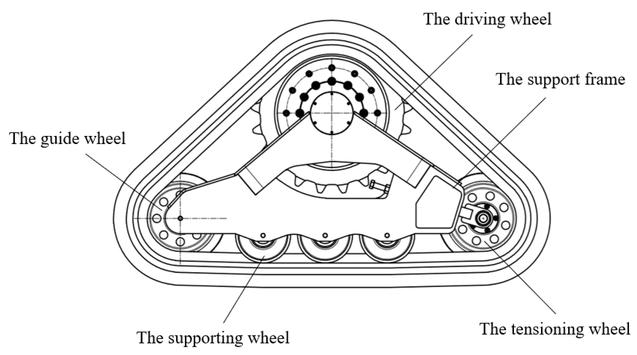
The front wheel of the chassis is designed as a triangular tracked wheel. As shown in
Figure 1, it includes a driving wheel, a guide wheel, a tensioning wheel and three branch weight wheels. When the vehicle is running, the engine transmits a certain torque to the driving wheel, and the driving wheel engages with the tracks to drive the tracks, so that the tracked wheels overcome a series of resistances to move forward [
13]. The steering wheel has a guiding effect on the track, which can avoid the track from running off and crossing the track in the process of driving and can also increase the contact area of the track and reduce the grounding ratio pressure [
14]. The tensioning wheel can adjust the tension of the track through its own swing, reducing the wear caused by the track relaxation or tightening, and thus can achieve better passing through the complex terrain [
15,
16]. The weight of the whole vehicle is carried by supporting wheels [
17], which restrain the lateral movement of the tracks and withstand the ground impact [
18].
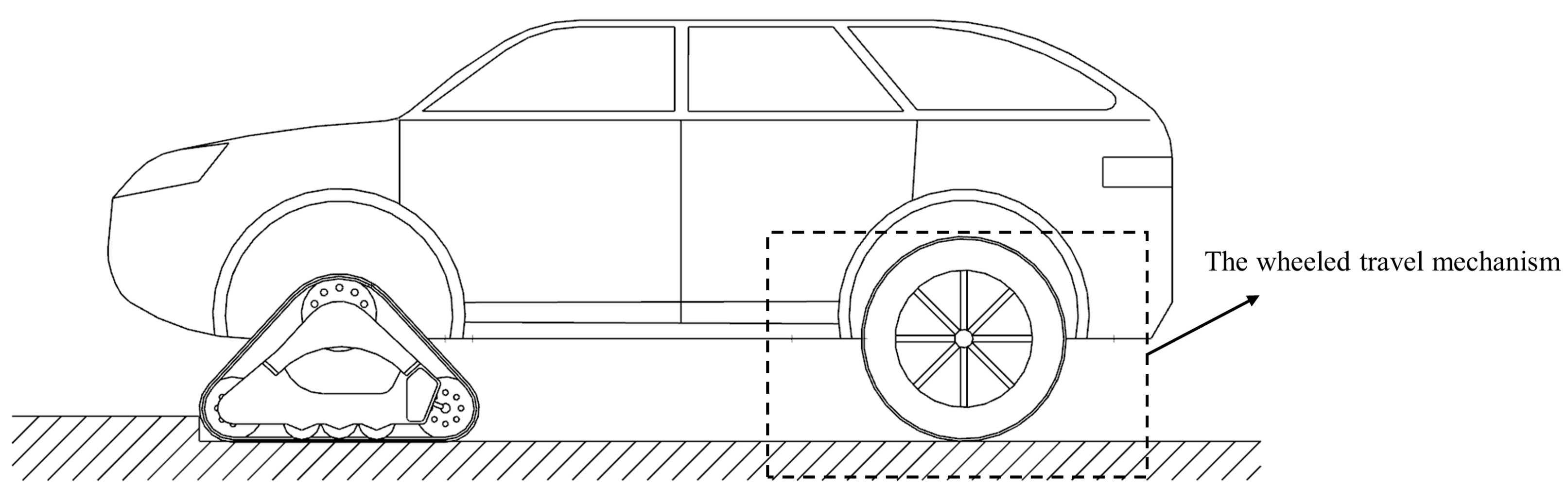
2.1.2. Design of Wheeled Travel Mechanism
The rear wheel of the chassis is designed as a wheeled travel mechanism composed of glue complex and curtain line, etc. The wheeled travel mechanism is widely used in modern vehicles due to its good maneuverability. During the driving process, the circular tire needs to bear the rear load of the vehicle, and the adhesion between the wheels and the ground has a deceleration and absorption effect on the vibration and impact of the vehicle, thus preventing the vehicle parts from violent vibration and reducing the service life. In addition, the tire also has traction and braking functions to transmit the power of the engine or brake to the road, while it can also steer and stabilize the vehicle to turn in the desired direction or remain straight [
19]. As shown in
Figure 2, it includes tire, rim and some other components.
2.2. Design of the Triangular Tracked Wheel
The triangular tracked wheel includes a driving wheel, a guide wheel, three supporting wheels, a tensioning wheel, a support frame and rubber tracks. The driving wheel is installed above the support frame, the guide wheel and the tensioning wheel are installed on the left and right edges of the support frame and three supporting wheels are installed at the bottom of the support frame. The radius of the driving wheel is an important parameter of the driving wheel, which is directly related to the driving torque and driving speed of the tracked vehicle. Additionally, the driving radius is proportional to the driving torque; when the driving wheel speed is constant, the radius of the driving wheel is proportional to the driving speed [
20]. The track parameters are shown in
Table 1.
2.3. Design of the Wheeled Travel Mechanism
The wheel is the most common travel mechanism used in vehicles, and tire, rim and some other components are included in the wheeled travel mechanism. The selection of the wheel was based on available data and standard parameters; rim and tire models were determined according to the design requirements of the wheel–track composite chassis and tire specifications, with selected models of 8.3–24. The rim width is 210 mm, rim diameter is 61 mm (24 inches), inner rim diameter is 15 mm (5.9 inches), tire section width is 21 mm (8.3 inches), height to width ratio is 0.65 and tire diameter is 995 mm.
3. Theoretical Analysis of Passability
The passability of a vehicle indicates its ability to pass through various complex roads, roadless areas and various obstacles at a high enough average speed. It depends mainly on the physical properties of the ground and the structural and geometric parameters of the vehicle. In this section, passability, including climbing performance and obstacle crossing performance, is analyzed theoretically.
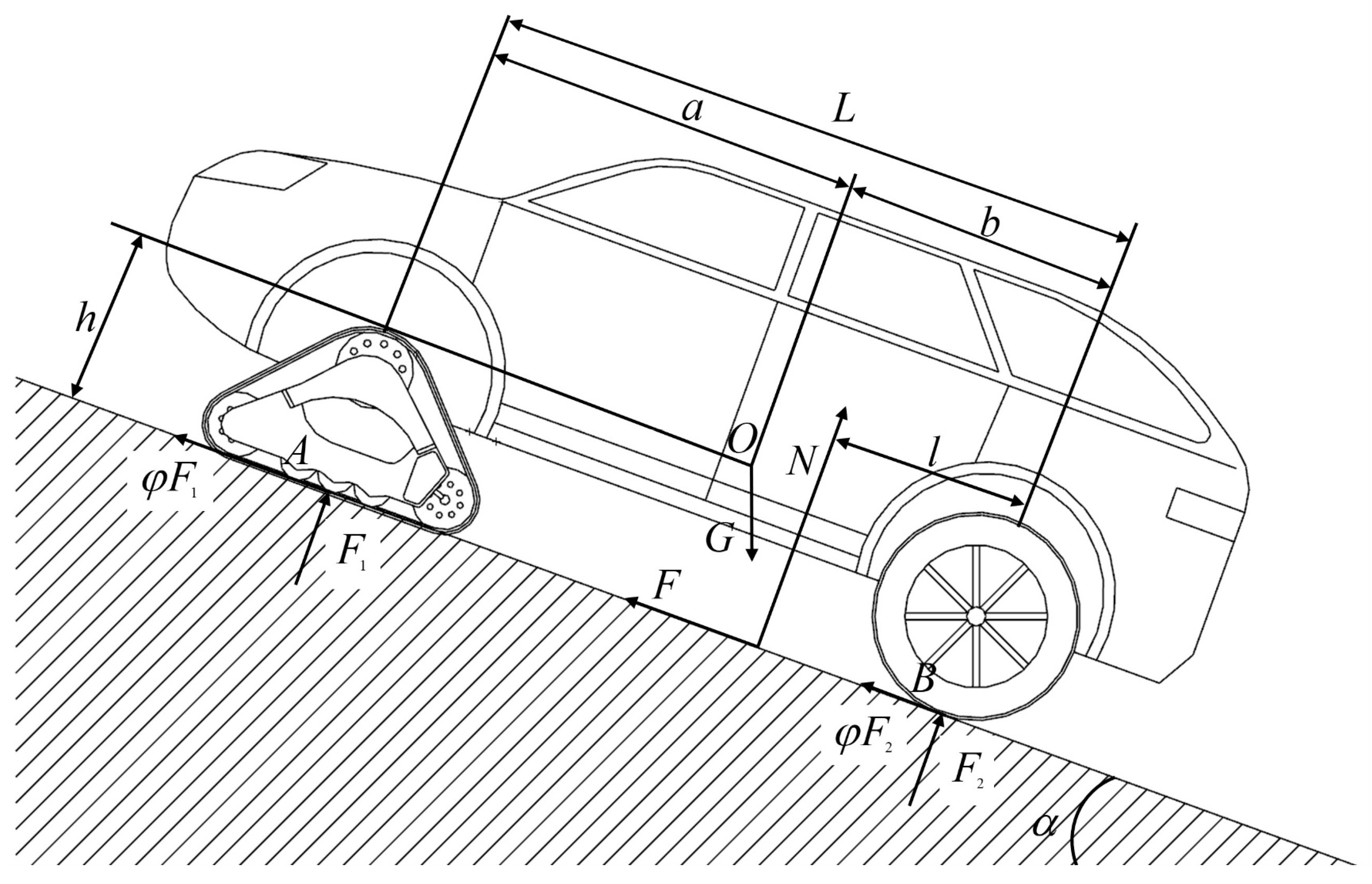
3.1. Theoretical Analysis of Climbing Performance
The wheel–track composite chassis has an extreme slope angle during climbing, and when the slope angle exceeds the limit value, the chassis will overturn. The forces on its longitudinal driving along a slope are shown in
Figure 3.
When the chassis rises at uniform speed, the torque balance equation of support point
B is:
In the equation, is gravity; is the support force; is the distance between the support force and the support point ; is the distance between the center of mass to the support point along the slope direction; a is the distance between the center of mass to the support point along the slope direction; is the slope angle; is the vertical distance between the center of mass to the slope.
In order to keep the wheel–track compound chassis from tipping over when going uphill, it needs to ensure
—namely, meet
. It is deduced that the relationship between the working slope angle and the position of the center of mass during the longitudinal uphill movement is as follows:
Replacing the relevant parameters into Equation (2), the maximum slope angle without tipping is 32.6 degrees when the chassis is driving uphill at a uniform speed along a longitudinal slope.
3.2. Theoretical Analysis of Obstacle Crossing Performance
In this paper, two types of obstacles, respectively vertical obstacles and trenches, are mainly considered.
3.2.1. Theoretical Analysis of the Chassis over the Vertical Obstacle
As is shown in
Figure 4, the process can be divided into two stages. In the first stage of
Figure 4a, the track plates on the guide wheel contact the edge of the vertical obstacle and rise to the highest point; the main center of mass is in the critical state of crossing the vertical obstacle. In the second stage of
Figure 4b, the main center of mass is over the edge of the vertical obstacle, and then the track bottom is also on the vertical obstacle and in the horizontal state. Finally, the chassis completely crosses the vertical obstacle [
21].
A force analysis of the triangular tracked wheel when crossing the vertical obstacle is shown in
Figure 5.
When the chassis crosses the vertical obstacle, the static balance equation is as follows:
In the equation, G is the total gravity of the whole machine; is the reverse force of the vertical obstacle; is the reverse force of the ground for the triangular tracked wheel; is the reverse force of the ground for the wheeled travel mechanism; is the wheelbase; is the maximum grounding length of the track when crossing the vertical obstacle; a is the distance between the center of mass and the front axis; b is the distance between the center of mass and the rear axis; is the vertical obstacle height; is the distance between the center of mass and axis of the driving wheel; is the attachment coefficient; is the angle between and horizontal line; is the swing angle of the triangular tracked wheel when crossing the vertical obstacle.
The obstacle height of the triangular track climbing over the vertical obstacle still needs to meet
In the equation, is the grounding length of the triangular tracked wheel; is the horizontal distance between the front edge of the triangular tracked wheel contacting ground and the front edge of the guide wheel.
When replacing the relevant parameters into Equation (4) and calculating the maximum height of the vertical obstacle, it is 228 mm.
A force analysis of the rear wheel travel mechanism when crossing the vertical obstacle is shown in
Figure 6.
When the rear wheel climbs over the vertical obstacle, the static balance equation is as follows:
In the equation, is the reverse force of vertical obstacle height acting on the front wheel; is load of the rear axle; is the wheelbase; is the tire diameter; is the distance between the center of mass and the front axle; is the attachment coefficient; is the angle between and the horizontal line.
According to the geometric relationship,
Put the upper type into Equation (7), and when the rear wheel contacts the vertical obstacle, the equation for the vertical obstacle height of the unit wheel diameter is as follows:
According to Equation (8), the height of the vertical obstacle of the unit wheel diameter of the rear wheel, , increases with decreases in . In addition, the value of the rear wheel to cross the vertical obstacle is always improved when the value of is relatively large, regardless of how the quality of the whole machine is distributed between the axes.
Replacing the relevant parameters into Equation (8), the maximum height is 398 mm.
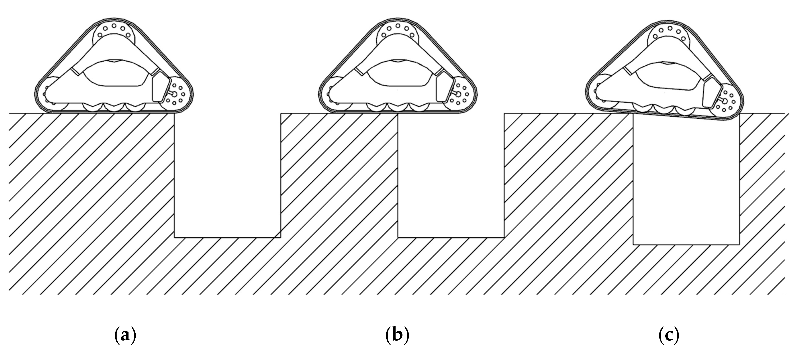
3.2.2. Theoretical Analysis of the Chassis over a Trench
As shown in
Figure 7, the process can be divided into three stages. In the first stage of
Figure 7a, the grounded front edge of the triangular tracked wheel contacts the edge of the trench and gradually leaves the ground in a suspended position. In the second stage of
Figure 7b, the center of mass of the triangular tracked wheel crosses the edge of the trench and is about to be suspended, with the triangular track in an inclined position. In the third stage of
Figure 7c, the grounded front edge of the triangular tracked wheel reaches the other edge of the trench, and then the triangular track is horizontal and completely across the trench [
22]. The width of a triangular tracked chassis across a trench is related to the track grounding length of the chassis and the position of the center of gravity of the entire chassis [
23], and the ability of a wheel–tracked composite chassis to cross a trench in this study was evaluated using a horizontal trench, taking into account safety aspects.
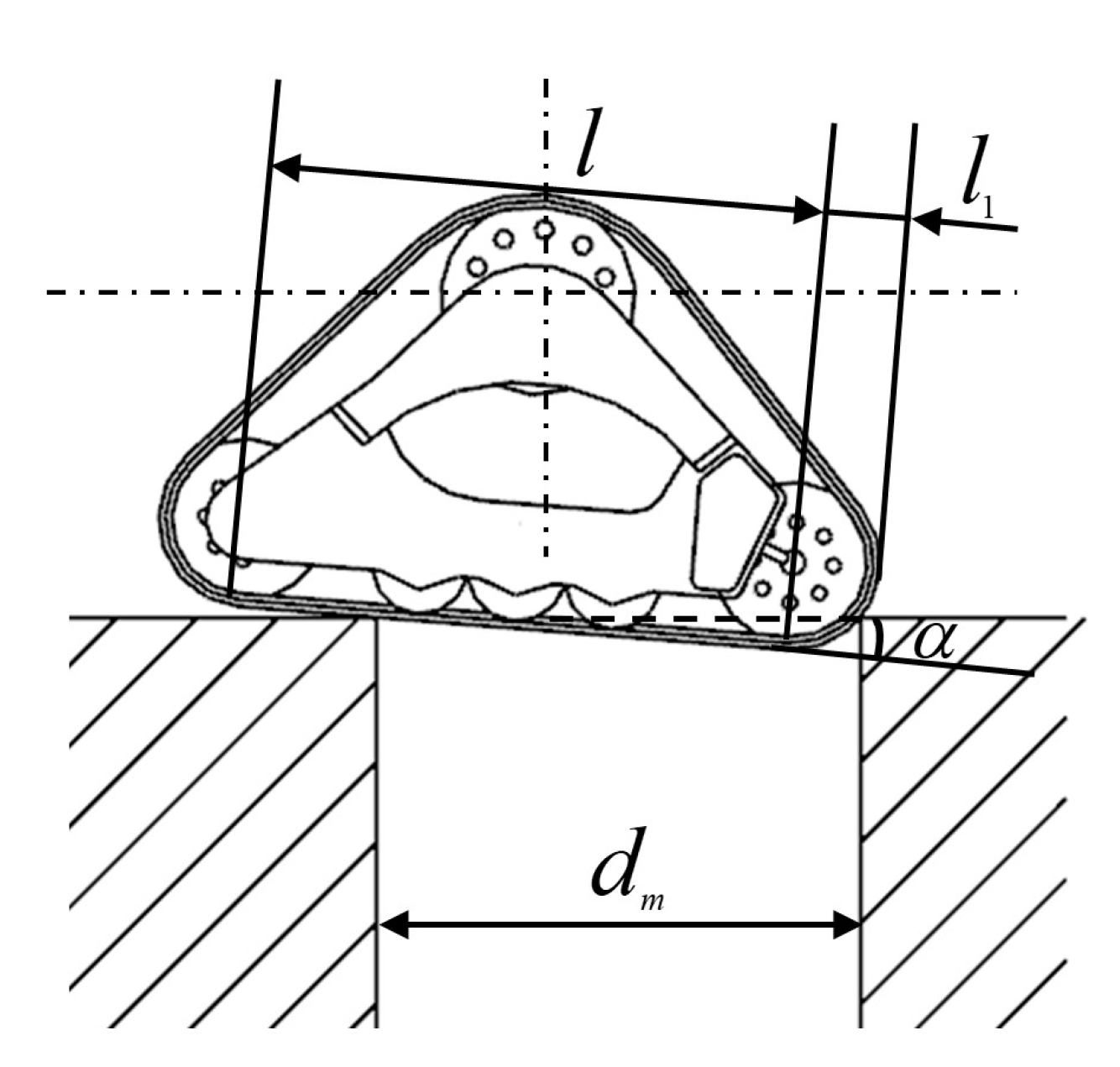
As is shown in
Figure 8, the width when the grounded front edge of the guide wheel contacts the other edge of the trench is the maximum one.
The equation that the triangular tracked wheel can span the maximum width of the trench is as follows:
Replacing the relevant parameters into the equation, the maximum width of the trench is 659 mm.
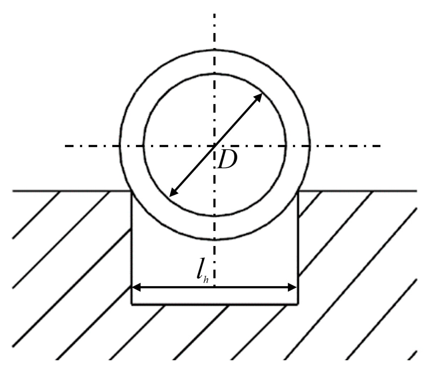
The rear wheel travel mechanism of the composite chassis is shown in
Figure 9.
The width of the chassis across the trench and the vertical obstacle height of the unit wheel diameter are as follows:
In the equation, is trench width; is wheel diameter.
Replacing the relevant parameters into the equation, the maximum width is 833 mm.
4. Dynamics Simulation Analysis Based on the RecurDyn
RecurDyn based on multibody dynamics calculations is capable of building multidisciplinary analytical problems into an achievable coupled computational simulation platform.
4.1. Dynamics Theory of Multibody Systems
Multibody dynamics equations of a system are developed for the analysis of the multibody dynamics of a structural system [
24]. The structure to be analyzed is geometrically modeled, and then realistic motion constraints and motion conditions are added to the structure. Finally, the structural system is analyzed using the relevant theory and dynamics equations in multibody dynamics analysis software to obtain simulation results.
4.1.1. Dynamics Analysis of Multibody Systems
The analysis method based on “computational multibody system dynamics” refers to the preparation of the corresponding program based on the theory of dynamics analysis, using the high-speed solution ability of a computer so as to achieve the purpose of the analysis. The main process can be divided into two parts: modeling and solution [
25].
4.1.2. Principles of Automatic Modeling
The kinetic equations described for a multibody system using absolute coordinates are generally in the form of
In the equation, is a position coordinate array; is the acceleration vector; is the Lagrange multiplier; is time; is the inertia matrix of system; is the system constant; is the Jacobian constraint matrix; is the constraint equation.
4.1.3. Establishment of the Control Equation
The control equations are first established by separating each rigid body independently, then establishing the dynamic equations of each rigid body based on Lagrange’s equations, and then listing the constraint equations through the connection relationship between the kinematic suits of the components. For a single rigid body, its Lagrange’s equation is
In the equation, is the generalized coordinate of the th rigid body in the system;
is the Lagrangian term, is defined and and represent the system kinetic energy and potential energy, respectively; is the generalized force of the th rigid body; is the number of rigid bodies.
The constraint equation for the system is
In the equation,
is the number of constraints; the formula for Equation (13) in matrix form is
In the formula,
is all the active force sustained by the rigid body, removing the generalized force corresponding to the generalized elastic force part;
is the stiffness matrix;
is the system mass matrix. Bring formula for Equation (15) into the formula for Equation (14), we get
Among
is a generalized force of the corresponding velocity quadratic term. Change the formula for Equation (17) into the following matrix block form:
in the obtained formula for Equation (18) is the system flexible body dynamic equation. is the amount of movement of the rigid body; is rotation of the rigid body; the superscript is a transposition; is movement acceleration; is rotational acceleration; is deformation.
After combining the various rigid bodies of the system, the Lagrange equation is
and the constraint equation is
The combination of the formulas for Equations (19) and (20) is the flexible multibody systems control equation.
is the Jacobian matrix of the constraint equation [
26].
4.2. Establishment of the 3-Dimensional Model
Based on multibody dynamics, RecurDyn provides a specialized toolkit that can be more convenient for specific applications in relevant industries, such as its track creation toolbox, which can conduct motion simulation of various track driving mechanisms [
27].
As shown in
Figure 10, this study used UG software to synthesize the frame and tires into a rigid body so that the entire mobile ground is divided into two parts: the tracked travel mechanism and the wheeled travel mechanism–frame The structural parameters of the wheel composite chassis are shown in
Table 2.
4.3. Constraints of the Model
To effectively simulate the driving process of the wheel composite chassis, constraints are necessary to be added between the components, as shown in
Table 3.
The fixed subsets are added between the track support frame and the frame, and the same restraint is added between the tire and the frame. The rotating subsets are added between the drive wheels and the frame, and the same restraint is added between the supporting wheels, tensioning wheels, guide wheels and the track support frame. Finally, the solid contact between the wheels and the ground is established.
4.4. Simulation Analysis of Wheel–Track Composite Chassis Dynamics
In this section, based on RecurDyn, the wheel–track composite chassis is simulated under different working conditions to analyze its performance parameters.
4.4.1. Dynamics Simulations in Different Terrains
According to the structural parameters of a rescue vehicle driving system, the force of a triangular crawler was analyzed by Hu and some others [
28], and the corresponding multibody dynamics model was established by using the Track-HM module in the multibody dynamics software RecurDyn. By changing the vehicle speed, pre-tensioning force and road surface, which affect the crawler tension force, multiple sets of simulation calculations were performed to obtain the force of the crawler during the motion cycle under different working conditions.
The software of RecurDyn can build ground models of hard and soft pavement types by setting different parameters [
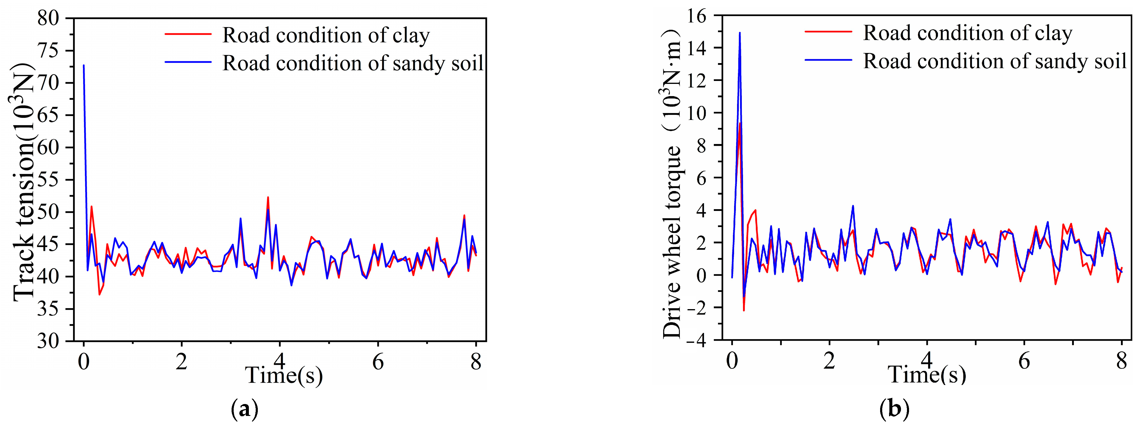
29]. The simulation shows a track tension diagram and a drive wheel torque diagram traveling in both terrains, as shown in
Figure 11.
The blue curve in the figure represents the wheel–track composite chassis on clay, and the green curve represents the chassis on sandy loam. According to
Figure 11, the simulation results show that the chassis can both pass through clay and sandy loam terrain and that the track tension and driving torque are similar. According to
Figure 11a, the track tension value fluctuates above and below 43 kN, reaching a minimum at 0.3 s and a maximum at 3.8 s. According to
Figure 11b, the driving torque fluctuates above and below 23 kN, reaching a minimum driving torque at 0.1 s and a maximum at 0.2 s. After 1.4 s, the driving torque fluctuated more stably as the chassis traveled on clay.
4.4.2. Dynamics Simulation of Different Slope Angles
Chen and some others [
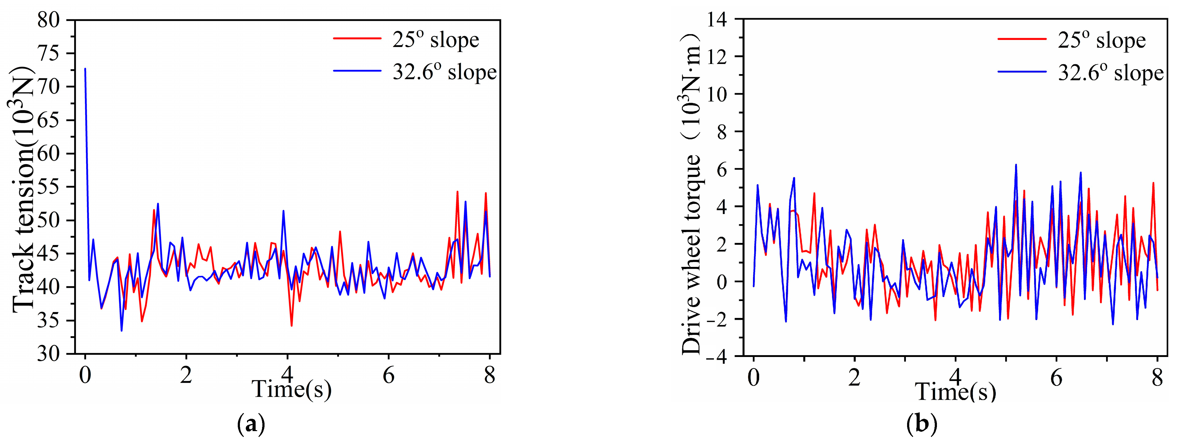
21] studied a small hedge trimmer crawler chassis, and they analyzed the lateral and longitudinal stability of the crawler chassis on slopes and the overrunning performance in the process of going over vertical walls and crossing trenches in a similar way. The theoretical value of the maximum climbing of the wheel–track composite chassis was 36.5°, while for most agricultural land, the maximum slope value is not more than 25°, so the slope values selected for the simulation were 25° and 36.5°. The same parameters derived from the wheel–track composite chassis under two kinds of slope driving were imported into a graph for comparison and analysis, so as to derive the change law of each parameter during the climbing process of the chassis, as shown in
Figure 12.
The blue curve in the figure represents the chassis on a 25° slope, and the green curve represents the chassis on a 32.6° slope. According to
Figure 12, the simulation results show that a slope of 32.6° can be passed. When the chassis travels on the 25° slope, the track tension fluctuates at 42 kN, reaching the minimum at 4.1 s and the maximum at 7.3 s. As the chassis travels on a 32.6° ramp, according to
Figure 12a, the track tension fluctuates around 44 kN, reaching a minimum at 0.7 s and a maximum at 7.5 s. According to
Figure 12a, the driving torque fluctuation of the chassis when driving on the 32.6° slope is greater, and the maximum driving torque is greater than the maximum value when the chassis is driving on the 25° slope, which shows that when the chassis is driving on the larger slope, the required driving force will be greater.
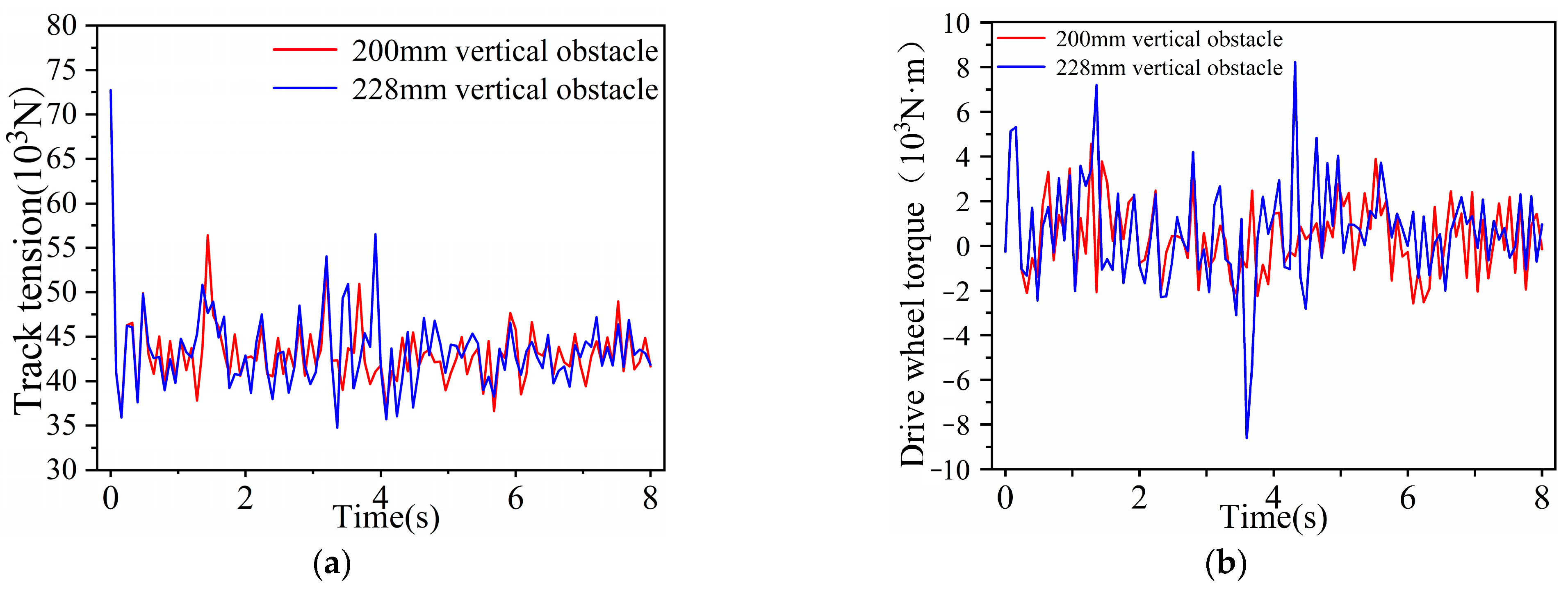
4.4.3. Dynamics Simulation of Different Vertical Obstacle Heights
The maximum vertical obstacle height that the wheel–track composite chassis can pass is 228 mm, so the vertical obstacle height was 200 mm and 228 mm during the simulation analysis, as is shown in the
Figure 13.
The blue curve in the figure represents a height of vertical obstacle of 200 mm, and the green curve represents a height of 228 mm. According to
Figure 13, the simulation results show that the composite chassis can cross a vertical obstacle with a height of 228 mm. When the chassis crosses a 200 mm vertical obstacle, as shown in
Figure 13a, the track tension fluctuates around 43 kN, reaching the minimum at 1.1 s and the maximum at 4.2 s. As the chassis crosses a 228 mm vertical obstacle, the track tension fluctuates around 45 kN, reaching a minimum at 3.3 s and a maximum at 3.9 s. The chassis fluctuates when crossing a 228 mm vertical obstacle, and the required driving torque is greater than the chassis when crossing a 200 mm vertical obstacle.
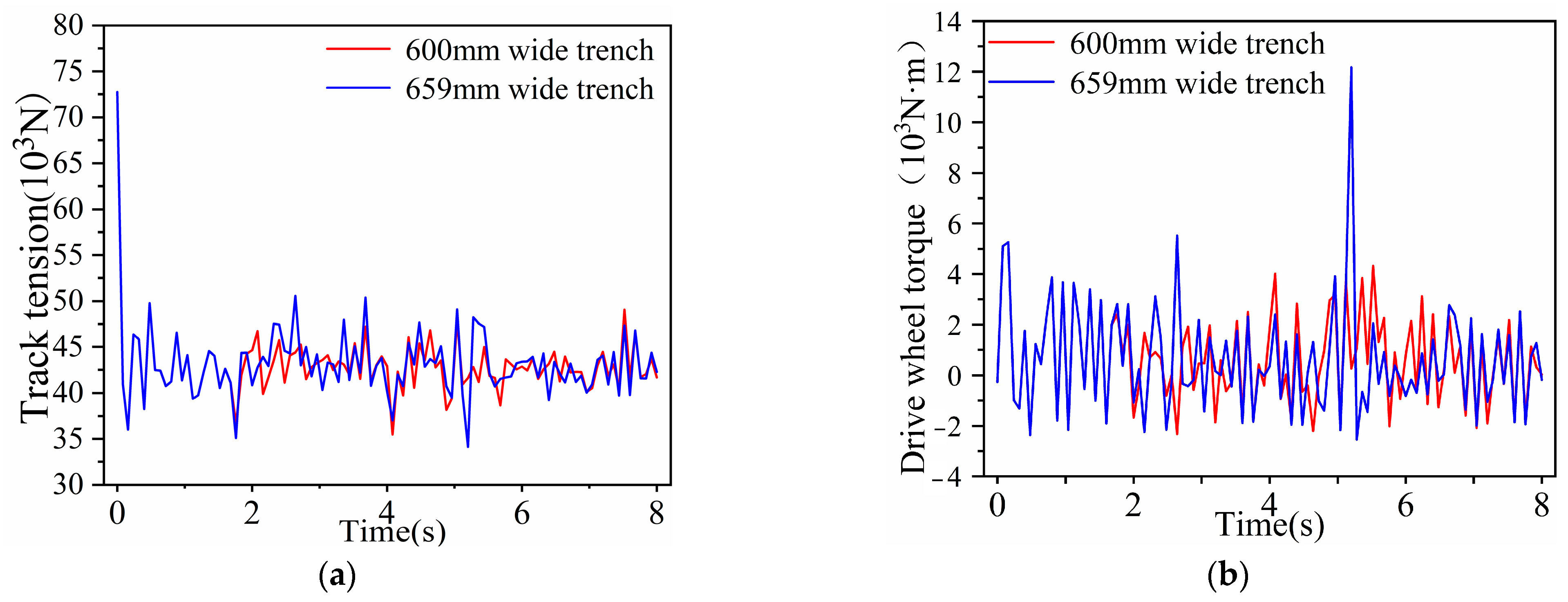
4.4.4. Dynamics Simulation of Different Trench Widths
The maximum trench width of the wheel–track composite chassis is 659 mm, and the two sets of parameters were 600 mm and 659 mm during the simulation analysis, as shown in the
Figure 14.
The blue curve in the figure represents a trench width of 600 mm and the green curve represents a trench width of 659 mm. According to
Figure 14, the simulation results show that a trench width of 659 mm can be passed through. The chassis fluctuates around 40 kN across the width of 600 mm trenches, reaching a minimum at 3.6 s and a maximum at 5.2 s. According to
Figure 14a, the track tension of the track fluctuated at 42 kN across a trench width of 659 mm, reaching a minimum at 3.5 s and a maximum at 4.3 s. According to
Figure 14b, the driving torque required for the chassis across a 659 mm trench is greater than that required across a 600 mm trench.
5. Conclusions
A wheel–track composite chassis was designed to improve the passability of a vehicle. Combined with the model of the chassis built by RecurDyn, a simulation analysis was carried out to obtain the change in the track tension and driving torque.
(1) Through the passing theoretical analysis of the wheel–track composite chassis and the chassis model simulation analysis, the chassis can pass through clay and sandy loam terrain, climb over a slope of 36.2°, and can cross the height of a vertical obstacle of 228 mm and the width of a trench of 659 mm.
(2) The track tension fluctuated around a certain value regardless of the road surface on which the wheel–track composite chassis was driven. When the chassis was driving on a flat road, the fluctuation of the track tension value was the smallest. The fluctuation of the track tension value was greater when the chassis was going uphill and through obstacles.
(3) High driving torque was required when the tracked wheels passed over inclined, obstructed and trenched surfaces. The chassis was designed to improve the vehicle’s ability to operate in complex and diverse unstructured conditions. Therefore, we should focus on the design and study of the drive wheels.


