Article

Modeling and Fuzzy Feedforward Control of Fuel Cell Air Supply System

School of Automotive Studies, Tongji University, Shanghai 201804, China
*
Author to whom correspondence should be addressed.
World Electr. Veh. J. 2021, 12(4), 181; https://doi.org/10.3390/wevj12040181
Submission received: 25 August 2021 / Revised: 20 September 2021 / Accepted: 30 September 2021 / Published: 9 October 2021

Abstract

:
As an important part of the fuel cell subsystem, the air supply system of the proton exchange membrane fuel cell (PEMFC) plays an important role in improving the output performance and durability of fuel cells. It is necessary to control the oxygen excess ratio of fuel cell systems in the process of variable load, preventing the oxygen starvation in the loading process and excessive parasitic power consumption caused by oxygen saturation. At this time, the modeling of fuel cell systems and the development of control strategies are critical. The development of a control strategy depends on the construction of the control model. Aiming at the difficulty of air supply system modeling, this paper uses radial basis function (RBF) neural network and state equation method to establish the dynamic model of air supply systems. At the same time, PID, fuzzy logic plus PID (FL + PID), feedforward plus PID (FF + PID), fuzzy feedforward plus fuzzy PID (FF + FLPID) control strategy are proposed to control the oxygen excess ratio of the system. The simulation results show that fuzzy feedforward plus fuzzy PID (FF + FLPID) has the best effect and the oxygen excess ratio can be followed in 1 s.

1. Introduction

The PEMFC air supply subsystem is mainly composed of an air filter, air compressor, intercooler, humidifier, pipeline and variable nozzle, as shown in Figure 1. A large number of studies have been proposed on system model and control strategies of PEMFC systems.
A widely accepted fuel cell air supply system model was proposed by Pukrushpan et al. [1], in which the air compressor model adopted the Moraal et al. [2] semi-mechanistic and semi-empirical model. Sankar et al. [3] established the dynamic equation of the air supply system by using the conservation law. Since there is a coupling relationship between the mass flow, speed and pressure ratio of the air compressor, the mass flow was directly fitted by polynomial. Baroud et al. [4] fitted the empirical formula of compressor mass flow based on experience and measured data. Michael et al. [5] used the equivalent circuit to simulate the air supply system and established a dynamic model. Most of the above are empirical fitting or polynomial fitting of the compressor model, but it is difficult to fit the nonlinear coupling relationship between the flow rate, pressure ratio and speed of the compressor in these ways, so this paper proposes the method of RBF neural network fitting.
The control of oxygen excess ratio at the cathode side has always been a point of concern. PID control [6] and model predictive control [7] have a lot of computation, sliding mode control [8] can be used but sometimes there will be chattering, robust control [9] and feedback linear control [10] depend on modeling accuracy and fuzzy control [11] and are used in air supply systems.
In this paper, RBF neural network combined with measured data is used to build an air compressor model, which is used in the fuel cell air supply system. Fuzzy PID control of excess oxygen ratio based on fuzzy feedforward compensation is proposed for the first time. The paper is organized as follows: in Section 2, the PEMFC air supply system model and control problems are established. In Section 3, four control strategies are designed and the controller performance is verified through simulation. Finally, conclusions are presented in Section 4.

2. Materials and Methods

2.1. PEMFC Air Supply System Model

The fuel cell air supply system model includes an air compressor model, pipeline model, intercooler model, humidifier model, cathode model, and outlet flow model. The air supply system model is built based on three assumptions: 1. The gas satisfies the ideal gas law; 2. The temperature of the stack can be controlled to an ideal value and the temperature of the gas entering the stack is equal to the operating temperature of the stack; 3. The gas can be humidified to the ideal humidity.

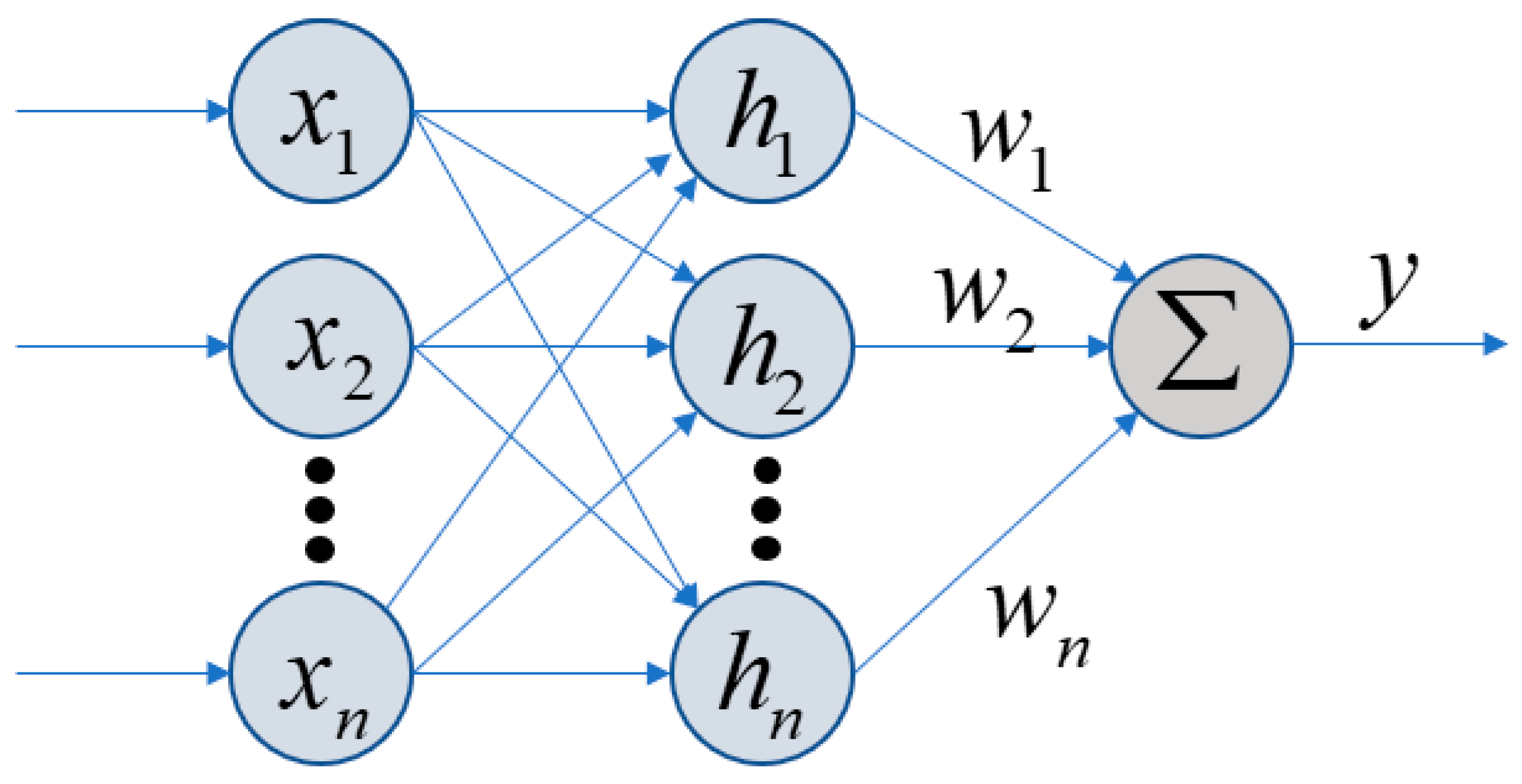
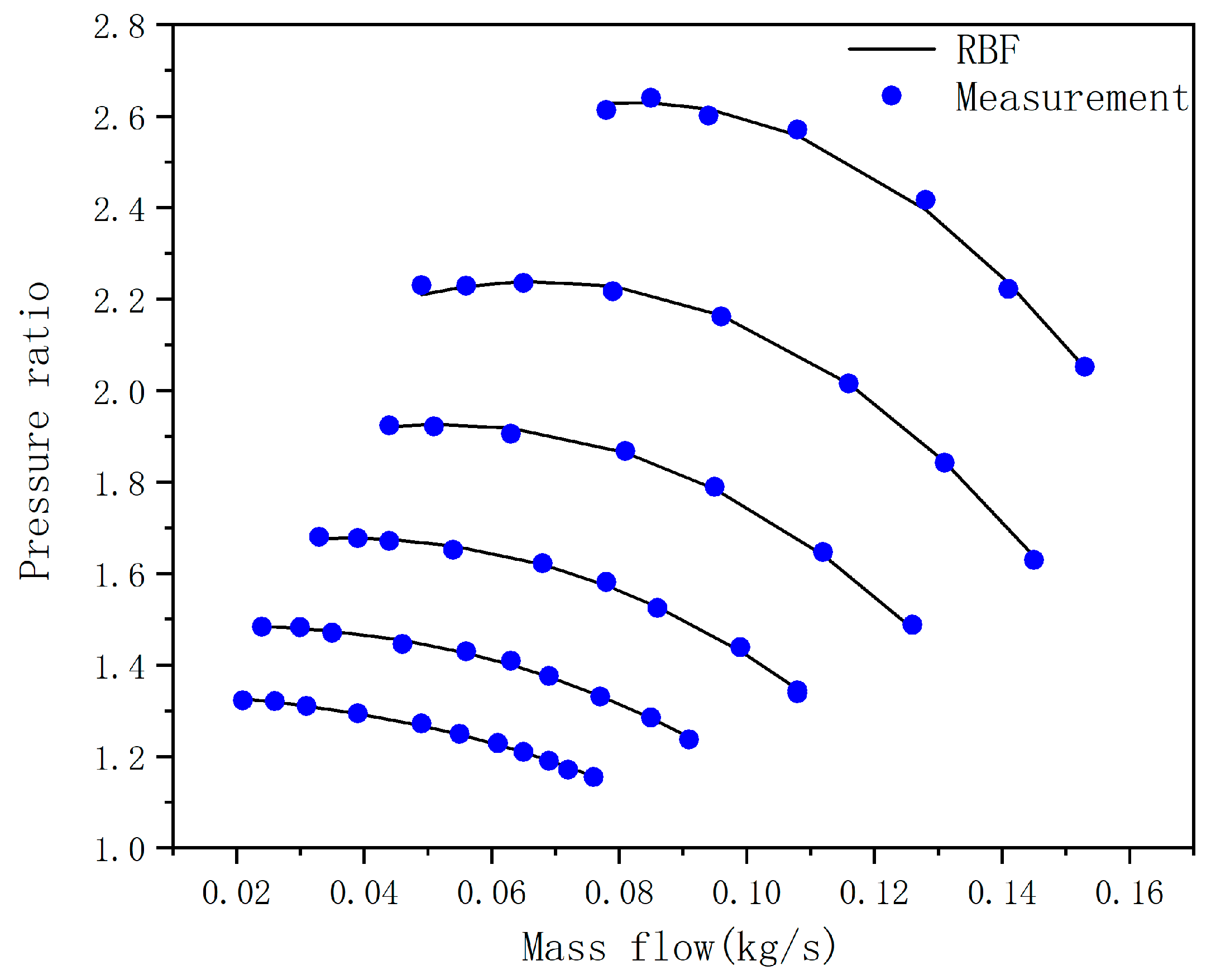
2.1.1. Compressor Model

The mass flow, compression ratio and speed of air compressor are coupled with each other, so it is difficult to use polynomial to accurately fit the relationship between them. At the same time, the accuracy is not high. The fitting error of using radial basis function (RBF) neural network is less than 4%.
For RBF neural network with multiple inputs and single outputs, the principle is shown in Figure 2. The control input is x = [ x 1 x 2 x n ] T , h j is the output of the neuron with hidden layer number j, h j expression is shown in Equation (1):
h j = exp ( x c j 2 2 b j 2 )
where c j = [ c i 1 c j 2 c jn ] is the center point vector value of the mesospheric neuron numbered j, b = [ b 1 b 2 b n ] T is the width of the Gaussian function applied, w = [ w 1 w 2 w n ] T is the weight of the neural network. The output of RBF neural network is shown in Equation (2).
y = w 1 h 1 + w 2 h 2 w n h n
The MAP in Figure 3 shows the data measured by adjusting the outlet back pressure at the same time every 10,000 r/min in the interval from 50,000–100,000 r/min of the compressor. There are altogether 53 groups of data, 43 groups as training sets and 10 groups as test sets, and RBF neural network is used for fitting. The fitting error is shown in Figure 4.
Meanwhile, when establishing the control-oriented fuel cell air supply system model, the compressor needs a certain response time in the process of changing load. In order to replace the response time of air compressor speed with first-order inertia link, the dynamic response of the compressor is shown in Figure 5. The trained air compressor neural network module and first-order inertia link together constitute a complete air compressor model, which provides a basis for subsequent control strategy development.

2.1.2. Pipeline and Cathode Modeling

Inside a PEMFC, the pressures of oxygen are related to the inlet mass flow rates, the reacted mass flow rates and the outlet mass flow rates of the gases. The equations of state are established according to the law of conservation of mass and the law of ideal gas. Some formulas are as follows:
dp sm dt = RT cp M atm V sm ( W cp W ca , in )
dp ca dt = RT ca M atm V ca ( W ca , in W ca , out W react )
W ca , in = k ca , in ( p sm p ca )
W react = M o 2 × nI st 4 F
where p sm and p ca represent inlet pipe pressure and cathode pressure, R is the universal gas constant, M atm is molar mass of the atmosphere, T cp and T ca represent compressor outlet temperature and cathode temperature, V sm and V ca represent intake pipe volume and cathode volume, W cp and W ca , in represent compressor outlet flow and cathode inlet flow, W react and W ca , out represent reaction flow rate and cathode outlet flow rate, k ca , in represents inlet mass flow rate coefficient, M o 2 is the molar mass of oxygen, n is number of single batteries, I st is current, F is the Faraday’s constant.

2.1.3. Intercooler and Humidifier Modeling

After passing through the air compressor, the air becomes high temperature and high pressure gas with low relative humidity. Direct entry into the stack will lead to dry film, enlarged ohmic impedance and other adverse effects. Therefore, it is necessary to humidify and cool the compressed gas. At this point, it is assumed that the intercooler is an ideal component. When the gas enters the intercooler, the gas flow rate and pressure do not change, and the gas can be cooled to the ideal temperature. Meanwhile, since the relative humidity is related to the temperature and pressure of the gas, the mathematical model of the intercooler is established as follows:
φ 1 = P v 1 p s
log 10 ( p s ) = 1.69 × 10 10 T 4 + 3.85 × 10 7 T 3 3.39 × 10 4 T 2 + 0.143 T 20.92
d 1 = m v 1 m a 1 = M v M a p v 1 p a 1
φ 1 = d 1 M a M v p a 1 p s
where φ 1 represents the relative humidity, P v 1 is the partial pressure of water vapor in the gas, p a 1 is the partial pressure of dry air, p s is the partial pressure of water vapor saturation at the current temperature, M v and M a represent the molar mass of water vapor and dry air, respectively, T is the temperature of the intercooler after cooling.
In the study of the dynamic response of air supply, it can be assumed that the gas is humidified to the ideal relative humidity. During this process, the temperature and pressure of the gas do not change.
φ 2 = p v 2 p s
d 2 = m v 2 m a 1 = M v M a p v 2 p a 1
W cp 2 = ( 1 + d 2 ) W air
W inj = W cp 2 W cp
where W cp is air flow into the humidifier, W air is dry air flow and the water vapor flow is W v . After humidifying to the ideal relative humidity, the moisture content also changes, at this time φ 1 becomes φ 2 , the moisture content changes from d 1 to d 2 , at this time the total gas flow becomes W cp 2 , the mass of water added is W inj .

2.1.4. Out Flow Modeling

The nozzle flow equation is often used to model the outlet flow, the formulas are as follows:
W out = C D A T p ca RT st ( p atm p ca ) 1 γ { 2 γ γ 1 [ 1 ( p atm p ca ) γ 1 γ ] } 1 2 p atm p ca > ( 2 γ + 1 ) γ γ 1
W out = C D A T p ca RT st γ 1 2 ( 2 γ + 1 ) γ + 1 2 ( γ 1 ) p atm p ca ( 2 γ + 1 ) γ γ 1
where W out represents the export gas flow, A T is the nozzle area, C D is the flow coefficient, γ is adiabatic coefficient, R is universal gas constant, T is stack temperature, p ca is cathode pressure, p atm is atmospheric pressure.

2.2. Four Different Control Strategies

In order to solve the control problem of oxygen excess ratio, PID, fuzzy logic plus PID (FL + PID), feedforward plus PID (FF + PID), fuzzy feedforward plus fuzzy PID (FF + FLPID) are used for simulation.

2.2.1. PID Controller

PID control is widely used in the industrial field because of its robustness to both linear and nonlinear systems. The schematic is shown in Figure 6, the formulas are as follows, where e t is taken as the deviation, the deviation between the optimal oxygen excess ratio and the return value of the oxygen excess ratio.
u pid ( t ) = k p e ( t ) + k i e ( t ) dt + k d de ( t ) dt
e ( t ) = λ opt λ

2.2.2. Feedforward plus PID Controller (FF + PID)

In order to make its response faster, the proportional coefficient k p will be increased. However, a high proportional coefficient will easily lead to overshooting and even instability of the system. If the proportional coefficient is reduced, the response will be too slow. The feedforward relationship can be determined according to the change of current I st . The feedforward relationship can be determined by fitting formulas or looking up tables. The schematic is shown in Figure 7.

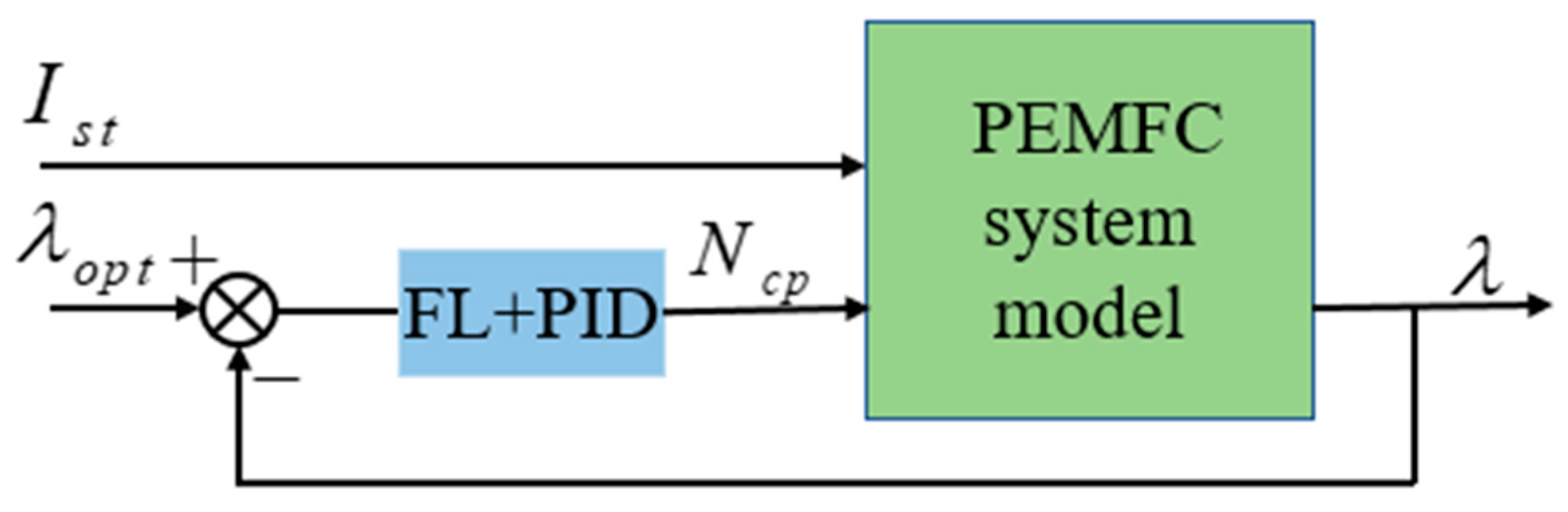
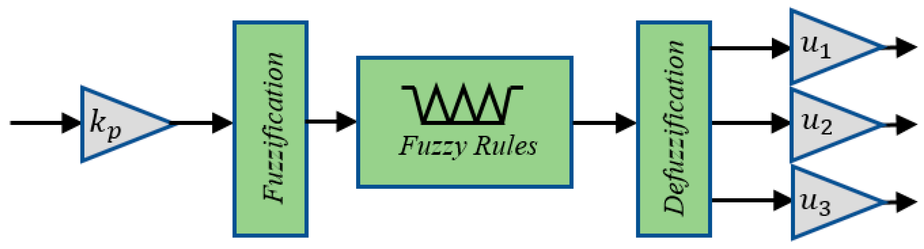
2.2.3. Fuzzy PID Control (FL + PID)

Fuzzy logic control is a modern control theory based on language rules and fuzzy reasoning in modern control theory. It combines human experience into actual control through language, and has the characteristics of fast response speed and strong fault-tolerant ability for nonlinear time-varying system. The system structure of fuzzy PID is shown in Figure 8.
Fuzzy control is generally composed of three steps. The first step is fuzzification, which converts clear input into fuzzy value. The second step is fuzzy reasoning, so that each appropriate input can get a certain result according to the rules. The third step is defuzzification and converting the combined results into specific control output values. The schematic diagram of fuzzy PID is shown in Figure 9, where k p is the quantization factor, u 1 , u 2 , u 3 is the scaling factor, and the fuzzy rules are matched through scaling transformation. The membership functions of input and output are shown in Figure 10, and fuzzy rules for fuzzy PID shown in Table 1.

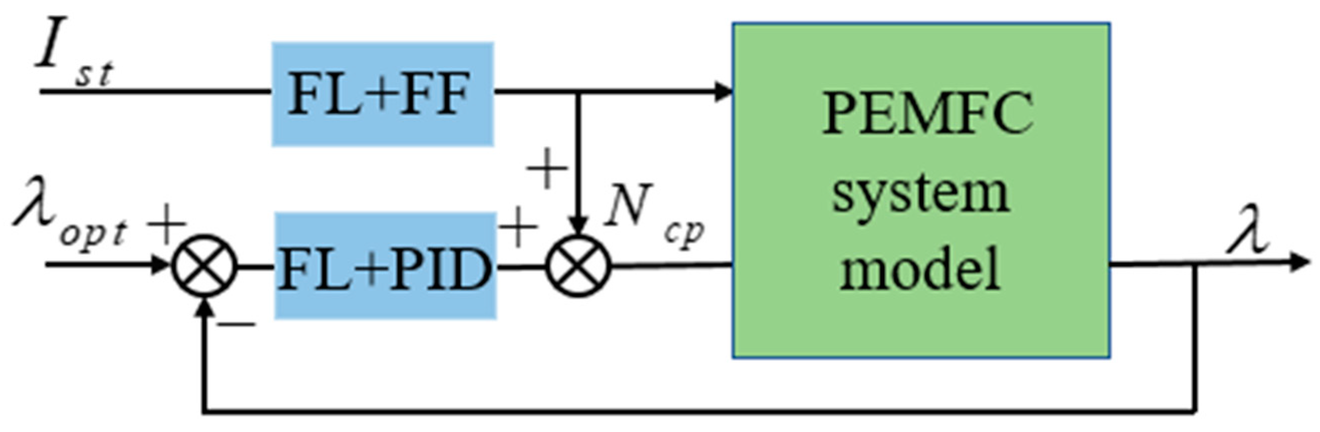
2.2.4. Fuzzy Feedforward plus Fuzzy PID (FF + FLPID)
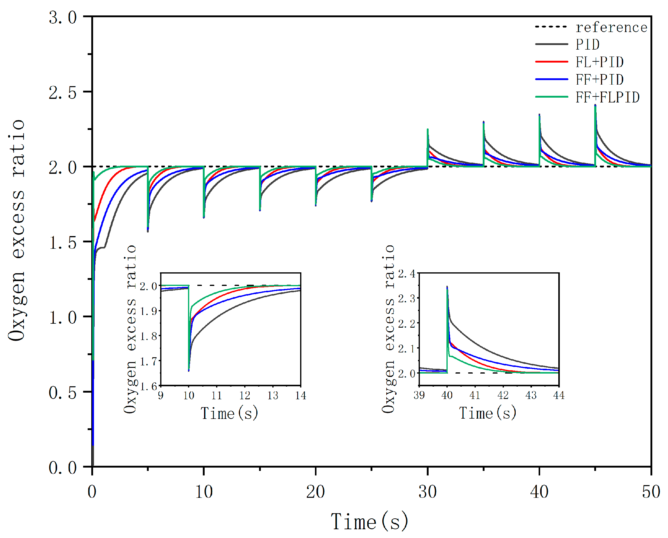
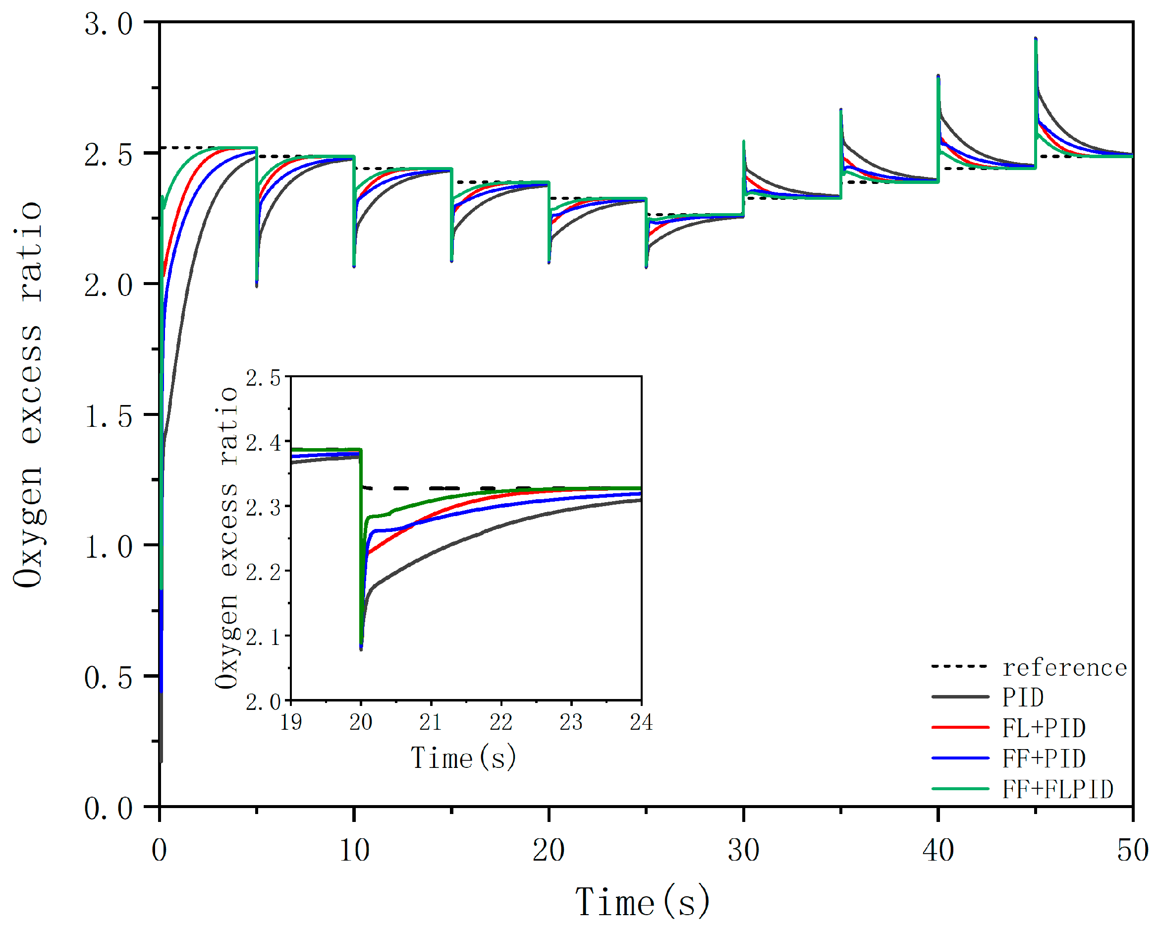
On the basis of feedforward control and fuzzy PID, the feedforward part is treated by fuzzy processing, and the fuzzy feedforward can be used instead of the common feedforward to realize the on-line adjustment. By obfuscating input data and adding fuzzy PID, a fuzzy feedforward control scheme is established. The system structure of fuzzy feedforward plus fuzzy PID (FF + FLPID) is shown in Figure 11.

3. Results

In order to verify the robustness and effectiveness of the simulation results, four control strategies of the fuel cell air supply system were simulated based on the established fuel cell air supply system model, and the simulation results were compared and analyzed. At the beginning, the oxygen excess ratio was set as 2. Since the optimal oxygen excess ratio was different under different working conditions, Zhang, H.K [12] proposed the following relation between the optimal oxygen excess ratio and the current, which is shown in Equation (19), to explore whether the four control strategies were still applicable in the case of changing the oxygen ratio, and to verify the effectiveness of each control strategy.
λ O 2 , ref = 5 × 10 8 I st 3 2.87 × 10 5 I st 2 + 2.23 × 10 3 I st + 2.5
Four different control strategies were used to control the oxygen excess ratio, in order to compare the control effect, given the current disturbance as shown in Figure 12, the current is perturbed every 5 s, ranging from 80 A to 180 A. Firstly, the oxygen excess ratio was controlled as 2, the dynamic responses of PID, fuzzy logic plus PID (FL + PID), feedforward plus PID (FF + PID), fuzzy feedforward plus fuzzy PID (FF + FLPID) are shown in Figure 13. At the same time, the enlarged images of two typical moments at 10 s and 40 s are given, the two typical working conditions in which the current jumps from 100 A to 120 A and the current jumps from 140 A to 120 A. In order to pursue the optimal net power output under different working conditions, the simulation figure of oxygen excess ratio according to Equation (19) is shown in Figure 14. Since the control effects of each control strategy at different operating points are basically the same, the control effects at a typical operating point of 10 s are shown in Table 2.

4. Discussion

It can be seen from Figure 12 that the system disturbance is the current once every 5s step, and the range of the current varies from 80 A to 180 A. When the oxygen supply cannot immediately catch up with the load, the oxygen excess ratio is flushed down. According to the simulation results of the four control strategies, using PID to control oxygen excess ratio reaches steady state in about 3.5 s. PID plus feedforward control (FF + PID) and fuzzy PID (FL + PID) control have better effects. Steady state is reached in 2.0 s and 1.5 s, respectively. Fuzzy feedforward and fuzzy PID (FF + FLPID) control effect is best, about 1 s can achieve steady state. At the same time to meet the net power output the oxygen excess ratio needs to change. Four control strategies were used for research, the simulation results are shown in Figure 14. The fuzzy feedforward and fuzzy PID control had the best effect too, and the steady state could be reached after about 1s. The reason for the best effect of fuzzy feedforward and fuzzy PID (FF + FLPID) is that a point close to the required speed after variable load is obtained through the fuzzy feedforward online coarse adjustment. Then, the specific speed value is obtained by using fuzzy PID on-line fine adjustment, so the response time and overshot are reduced.

5. Conclusions

In this paper, a model of PEMFC air supply system was established by using neural network and equation of state, the accuracy of air compressor modeling was greatly increased by using RBF neural network. The response problem of cathode oxygen excess ratio under variable load was described. Based on this model, four control strategies were designed to control the oxygen excess ratio, which are PID, fuzzy logic plus PID (FL + PID), feedforward plus PID (FF + PID), fuzzy feedforward plus fuzzy PID (FF + FLPID) The simulation results show that the fuzzy feedforward and fuzzy PID (FF + FLPID) control have the best effect, and the response time of oxygen excess ratio is reduced to 1 s. At the same time, in order to seek the maximum net power output the oxygen excess ratio needs to change. The following effect of fuzzy feedforward plus fuzzy PID (FF + FLPID) control still shows a more excellent effect.

Author Contributions

Conceptualization, S.X.; methodology, software, validation, formal analysis, writing—original draft preparation, writing—review and editing J.C.; visualization, B.Z.; project administration, H.M. All authors have read and agreed to the published version of the manuscript.

Funding

Open fund of State Key Laboratory of Compressor Technology: Research on core key technologies of compressor for full power fuel cell.

Data Availability Statement

No new data were created or analyzed in this study. Data sharing is not applicable to this article.

Conflicts of Interest

The authors declare no conflict of interest. The funders had no role in the design of the study; in the collection, analyses, or interpretation of data; in the writing of the manuscript, or in the decision to publish the results.

References

  1. Pukrushpan, J.T.; Stefanopoulou, A.G.; Peng, H. Control of fuel cell breathing. Control Syst. IEEE 2004, 24, 30–46. [Google Scholar]
  2. Moraal, P.; Kolmanovsky, I. Turbocharger Modeling for Automotive Control Applications. SAE Techn. Pap. Ser. 1999, 108, 1324–1338. [Google Scholar] [CrossRef]
  3. Sankar, K.; Jana, A.K. Nonlinear multivariable sliding mode control of a reversible PEM fuel cell integrated system. Energy Convers. Manag. 2018, 171, 541–565. [Google Scholar] [CrossRef]
  4. Baroud, Z.; Benmiloud, M.; Benalia, A.; Ocampo-Martinez, C. Novel hybrid fuzzy-PID control scheme for air supply in PEM fuel-cell-based systems. Int. J. Hydrogen Energy 2017, 42, 10435–10447. [Google Scholar] [CrossRef] [Green Version]
  5. Danzer, M.A.; Wilhelm, J.; Aschemann, H.; Hofer, E.P. Model-based control of cathode pressure and oxygen excess ratio of a PEM fuel cell system. J. Power Sources 2008, 176, 515–522. [Google Scholar] [CrossRef]
  6. Qi, Y.; Espinoza-Andaluz, M.; Thern, M.; Li, T.; Andersson, M. Dynamic modelling and controlling strategy of polymer electrolyte fuel cells. Int. J. Hydrogen Energy 2020, 45, 29718–29729. [Google Scholar] [CrossRef]
  7. Gruber, J.; Doll, M.; Bordons, C. Design and experimental validation of a constrained MPC for the air feed of a fuel cell. Control. Eng. Pract. 2009, 17, 874–885. [Google Scholar] [CrossRef]
  8. Matraji, I.; Laghrouche, S.; Jemei, S.; Wack, M. Robust control of the PEM fuel cell air-feed system via sub-optimal second order sliding mode. Appl. Energy 2013, 104, 945–957. [Google Scholar] [CrossRef]
  9. Talj, R.; Ortega, R.; Astolfi, A. Passivity and robust PI control of the air supply system of a PEM fuel cell model. Automatica 2011, 47, 2554–2561. [Google Scholar] [CrossRef]
  10. Wang, F.; Ouyang, Q.; Chen, J.; Su, H. Feedback Linearization Control of the Air Supply System of PEM Fuel Cells. In Proceedings of the 2015 10th Asian Control Conference (ASCC), Kota Kinabalu, Malaysia, 31 May–3 June 2015; Institute of Electrical and Electronics Engineers (IEEE): Manhattan, NY, USA, 2015; pp. 1–6. [Google Scholar]
  11. Ou, K.; Wang, Y.-X.; Li, Z.-Z.; Shen, Y.-D.; Xuan, D.-J. Feedforward fuzzy-PID control for air flow regulation of PEM fuel cell system. Int. J. Hydrogen Energy 2015, 40, 11686–11695. [Google Scholar] [CrossRef]
  12. Zhang, H.; Wang, Y.; Wang, D. Adaptive robust control of oxygen excess ratio for PEMFC system based on type-2 fuzzy logic Scheme. Inf. Sci. 2020, 511, 1–17. [Google Scholar] [CrossRef]
Figure 1. PEMFC air supply system.
Wevj 12 00181 g001
Figure 2. Principle of RBF neural network.
Wevj 12 00181 g002
Figure 3. Compressor map measurement and RBF training result.
Wevj 12 00181 g003
Figure 4. Training error of RBF.
Wevj 12 00181 g004
Figure 5. Dynamic response of compressor.
Wevj 12 00181 g005
Figure 6. Structure of PID controller.
Wevj 12 00181 g006
Figure 7. Structure of feedforward plus PID controller.
Wevj 12 00181 g007
Figure 8. Structure of fuzzy logic plus PID controller.
Wevj 12 00181 g008
Figure 9. Structure of fuzzy logic.
Wevj 12 00181 g009
Figure 10. Membership functions.
Wevj 12 00181 g010
Figure 11. Structure of fuzzy feedforward plus fuzzy PID controller.
Wevj 12 00181 g011
Figure 12. Stack current variation.
Wevj 12 00181 g012
Figure 13. Response of oxygen excess ratio for different control strategies.
Wevj 12 00181 g013
Figure 14. Response of variable oxygen excess ratio for different control strategies.
Wevj 12 00181 g014
Table 1. Fuzzy rules for fuzzy PID.
e K P K i K d
NBVLLS
NSLML
ZSSM
PSLML
PBVLLS
Table 2. Control effects of different control strategies at 10 s.
ControllersOvershoot (%)Settling Time (%5) (s)
PID17.52.51
FL + PID171.08
FF + PID171.63
FF + FLPID160.65
Publisher’s Note: MDPI stays neutral with regard to jurisdictional claims in published maps and institutional affiliations.

