Article

Receiver-Triggered Handshake Protocol for DTN in Disaster Area

Graduate School of Engineering, Information Systems Science, Soka University, 1-236 Tangi-cho, Hachioji-shi, Tokyo 192-8577, Japan
*
Author to whom correspondence should be addressed.
Future Internet 2015, 7(2), 152-169; https://doi.org/10.3390/fi7020152
Submission received: 13 March 2015 / Revised: 10 May 2015 / Accepted: 15 May 2015 / Published: 27 May 2015

Abstract

:
When a disaster hits a wide area, communication services for public use will be rendered unavailable. This will make it difficult to confirm the safety of people in the disaster area. A solution to this problem is to form delay/disruption tolerant networks (DTN) using mobile terminals of victims, those of rescuers, who serve as information carriers, and terminals (servers) in shelters. In this paper, we propose using a receiver-triggered handshake protocol for communication between these terminals. We have developed the bundle layer protocol for this handshake method. The proposed method has been implemented on a network simulator to build an evaluation environment. The disaster area has been modeled on an area around Shinjuku Station in Tokyo. Victims are randomly distributed in the area. We have compared the proposed method with Epidemic Routing and Spray and Wait in terms of the delivery rate at which messages reach their destinations, and the length of time taken for messages to reach their destinations. We have found that the delivery rate of the three methods are, more or less, the same, but that the proposed method is superior to the other two methods in terms of storage usage and battery consumption of terminals, and the number of bundles generated in the network.

1. Introduction

In recent years, there is a growing concern in society about the possibilities of earthquakes whose epicenters are directly below a major city. In the event of such a disaster, mobile terminals can be an effective means of communication but mobile communication networks are likely to be damaged. In fact, in the aftermath of the Great East Japan Earthquake, base stations were destroyed or damaged, and it took about one month before they were fully restored [1,2]
A type of network that is being studied to secure a communication infrastructure in the event of a disaster is a delay/disruption tolerant networks (DTN) [3]. Based on near-field communication and store-and-carry data transfer, the DTN makes data transfer possible, even in inferior communication conditions, such as frequent disruptions or disconnections of communications and large transmission delays. However, the DTN still has many issues to be solved, such as how to improve the delivery rate (rate at which messages reach their destinations) and how to reduce battery consumption of mobile terminals. Representative protocols used in DTN are Epidemic Routing and Spray and Wait. In Epidemic Routing, which is also known as infectious routing, a terminal that has data sends its copy to all the terminals to which it is connected. Advantages of this routing are that the delivery rate is relatively high and that the delay time is short. However, it has a problem of generating large traffic loads and consuming battery charge greatly. Spray and Wait allows a trade-off between data transfer delay and storage usage in relay nodes by adjusting the upper bound on the number of copies that can be made per message. However, a problem with Spray and Wait is that it is difficult to determine the appropriate upper bound in the aftermath of a disaster.
Our study focuses on using DTN to collect information about the safety of victims in a disaster area while mobile communication services are disrupted. The DTN consists of mobile terminals of victims and mobile terminals of information carriers, and shelter terminals. We propose using a bundle layer protocol that is based on a receiver-triggered handshake protocol. This protocol is intended to avoid network congestion, and reduce battery consumption and storage usage of mobile terminals by limiting the number of bundles that are generated. It has been implemented on a network simulator to build an evaluation environment. The disaster area has been modeled on an area around Shinjuku Station in Tokyo. Victims are randomly distributed in the disaster area. We have compared the proposed protocol with Epidemic Routing and Spray and Wait in terms of the delivery rate, and delivery time (the length of time taken for messages to reach their destinations). We have found that the delivery rate of the three methods are, more or less, the same, but that the proposed method is superior to the other two methods in terms of storage usage and battery consumption of terminals, and the number of bundles generated in the network. Section 2 summarizes related studies. Section 3 discusses the structure of DTN that will be formed after a disaster, implementation issues, and our performance objective for the DTN. Section 4 proposes a bundle layer protocol that is based on a receiver-triggered handshake protocol. Section 5 presents the simulation environment we have built to evaluate the proposed protocol as well as evaluation conditions. Section 6 discusses the evaluation results. Section 7 gives conclusions and future issues.

2. Related Studies

2.1. Epidemic Routing and Spray and Wait

Epidemic Routing [4] is an infectious routing in which a transmission terminal floods bundles to all the relay nodes to which it is connected. This increases the probability with which a bundle reaches its destination terminal, resulting in a high delivery rate. A downside is that flooding of bundles can lead to network congestion. In addition, every time a terminal is connected to a relay node and transmits data, it consumes its battery charge, which is precious in a disaster situation. To sum up, Epidemic Routing tends to cause network congestion due to flooding of a large number of bundles, and consumes considerable battery charge due to frequent transmission of data.
Spray and Wait [5] sets an upper bound on the number of copies that can be generated. It can avoid flooding-induced network congestion, and enables terminals to save more battery charge than Epidemic Routing. A downside is that the delivery rate is lower because suppression of flooding reduces the probability at which the relay nodes that hold copies reach the destination terminal. Besides, in the aftermath of a disaster, when the extent of the damaged area or the number of victims is likely to be unknown, it is difficult to determine the appropriate upper bound on the number of copies instantaneously.
The characteristics of Epidemic Routing and Spray and Wait are summarized in Table 1.
Table 1. Characteristics of the existing methods.
ItemDelivery rateStorage usageLikelihood of network congestionBattery consumption
Method
Epidemic RoutingHighLargeHighLarge
Spray and WaitLow to highSmall to largeLow to highLarge

2.2. Other Related Studies

DTN that uses portable storage units was proposed in [6]. Using clusters to obtain information about victims who require rescue in an area where telecommunication services are disrupted was proposed in order to improve the efficiency of searching for these victims in [7]. An attempt to improve both delivery speed and delivery rate by calculating possible connection duration time and choosing to connect to those adjacent nodes with which connections can be established over a long period was proposed in [8]. A method of using DTN to enable a rescue team to share information in a disaster area was proposed in [9]. Specifically, the paper proposed a method in which a rescue team member who has a mobile terminal collects data on the disaster situation, and uploads the data to a server installed in a disaster response center quickly and reliably taking the degree of importance of each item of the collected data into consideration. A routing method that suppresses flooding of messages in DTN was proposed in [10]. Flooding messages is suppressed by defining a “super node”, and using a routing that is based on route information. Message ferries that interconnect clusters and carry messages were defined in [11,12,13]. Similarly, using DTN as a sensor network that incorporates traveling nodes was proposed in [14,15,16,17].
However, all these studies use a routing based on either Epidemic Routing or Spray and Wait. Therefore, they retain the problem of precious battery charge being consumed, which makes it difficult to use mobile terminals of victims to collect information about the safety of victims in the aftermath of a disaster. In addition, they do not propose any specific bundle layer protocol.

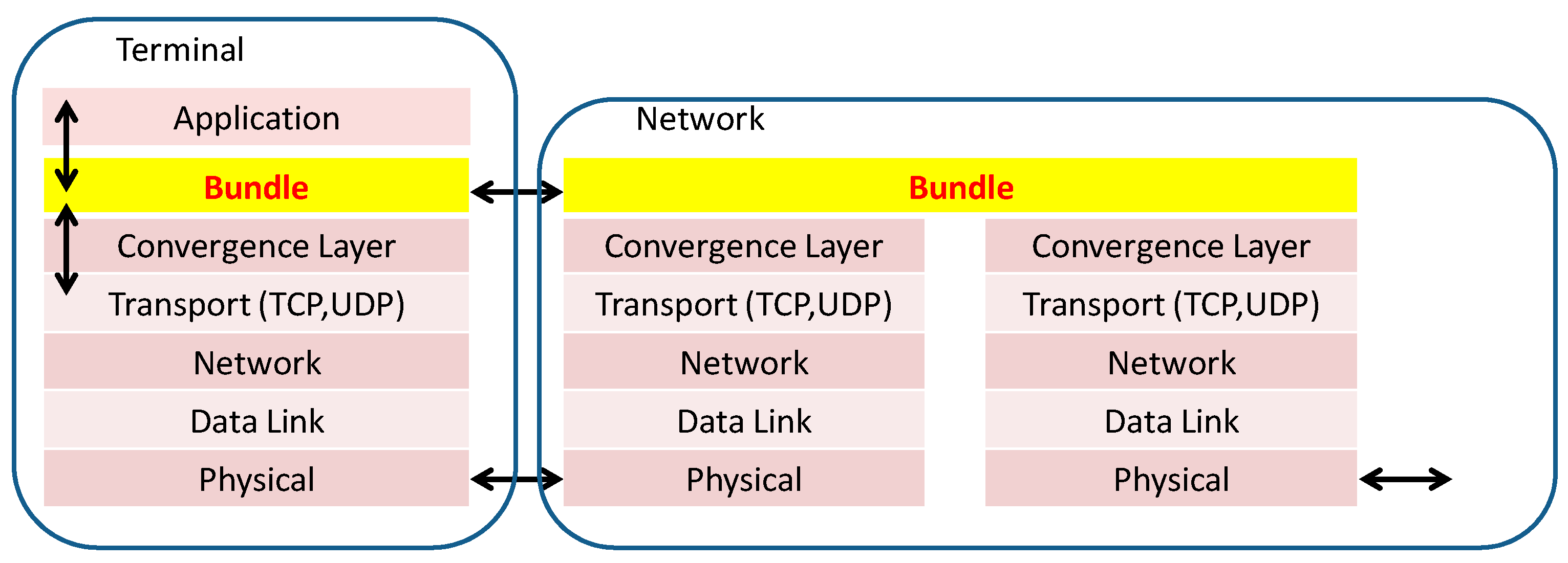
3. DTN Structure and Implementation Issues

This section describes the disaster environment assumed in this paper and our proposed DTN structure. It also identifies the target characteristics of the DTN, and implementation issues that must be solved.

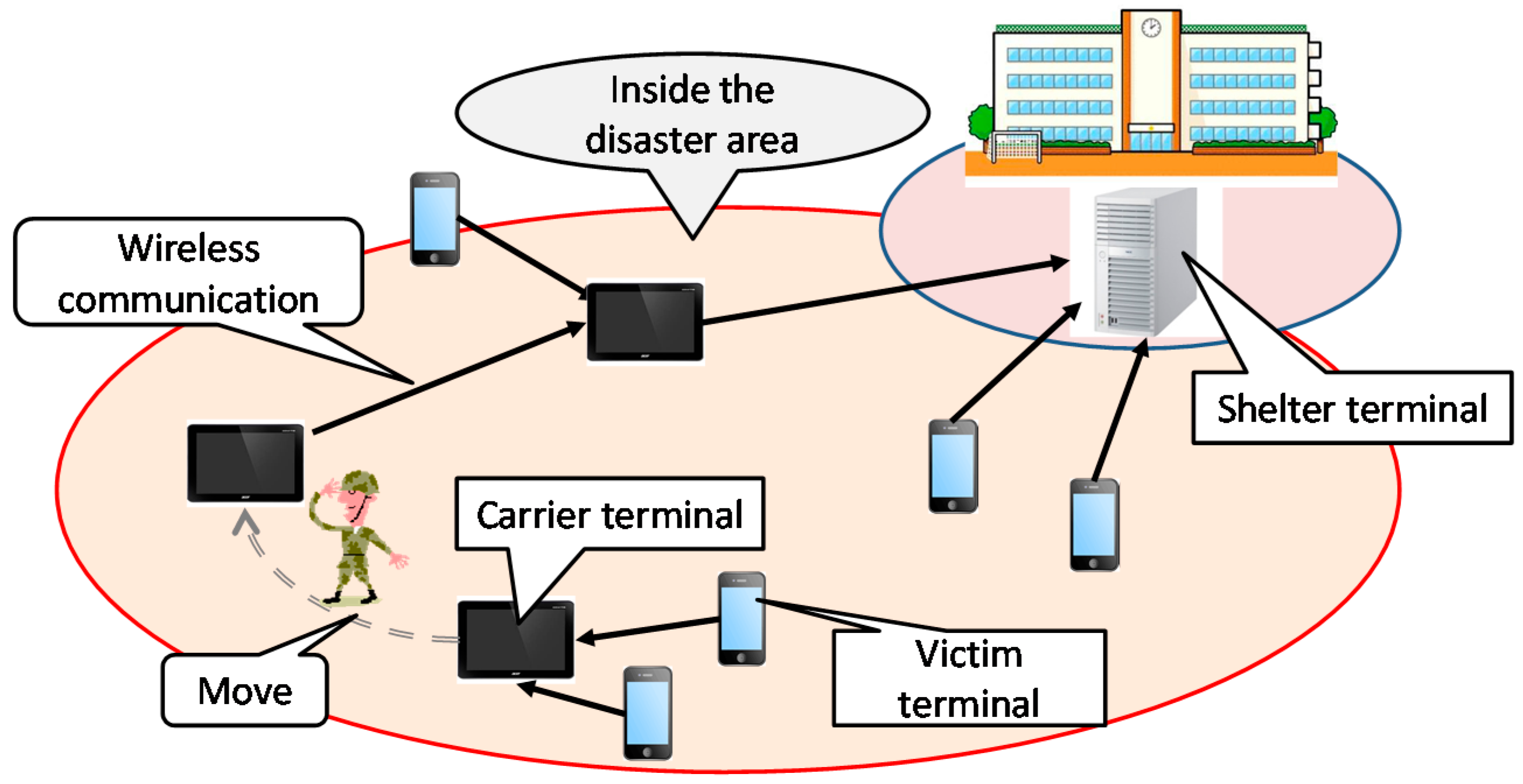
3.1. DTN Structure in a Disaster

In the event of a disaster, it is necessary to collect many types of information, such as information about the safety of disaster victims (safety confirmation information), information about the disaster area, information about the rescue operations, and information about first-aid tents if such tents have been installed. This paper focuses on the collection of safety confirmation information.
We assume the following disaster situation. The base stations for mobile communication services are damaged. A telecommunication terminal (shelter terminal) is installed in each shelter in the disaster area. Victims want to use their mobile phones to send their safety confirmation information to a shelter terminal. A shelter terminal stores safety confirmation information, and sends messages that contain this information to a telecommunication terminal that is mounted on a truck that has come to the disaster area to bring in relief supplies. When the truck leaves the disaster area and comes to an area where a wide-area network is operating, its terminal accesses the Internet and sends the messages to the victims’ loved ones who are outside the disaster area. Messages from the mobile terminals of victims are carried to a shelter terminal by what we call “information carriers” or just “carriers” in this paper. Specifically, they can be members of rescue teams, including those of the Self-Defense Forces. Carriers are assumed to have dedicated mobile terminals.
As shown in Figure 1, the DTN assumed in this paper consists of terminals of victims (victim terminals), terminals of carriers (carrier terminals), and shelter terminals. These terminals communicate using wireless transmission. How information is sent from a shelter terminal to the victims’ acquaintances outside the disaster area is outside the scope of this paper. The protocol stack used in the DTN is shown in Figure 2. The function of collecting safety confirmation information is implemented at the bundle layer.
Figure 1. Delay/disruption Tolerant Networks (DTN) structure in a disaster area.
Futureinternet 07 00152 g001
Figure 2. Protocol stack structure for communication in a DTN.
Futureinternet 07 00152 g002

3.2. Issues and Performance Objectives

Issue 1: Suppressing the number of bundle copies
Increasing the number of bundle copies, as is done by Epidemic Routing, raises the delivery rate, but increases the chances of network congestion. When congestion occurs, safety confirmation information cannot be sent. Therefore, it is necessary to suppress the number of flooding attempts.
Issue 2: Reducing battery consumption of victim terminals
Following a disaster, batteries of victim terminals cannot be recharged. Therefore, it is necessary to minimize battery consumption for sending bundles that contain safety confirmation information so that the period in which mobile terminals stay usable can be extended.
Issue 3: Reducing storage usage of carrier terminals
A large-scale disaster affects a large number of people. The greater the number of victims, the greater the number of bundles that each carrier terminal receives, and the larger its required storage capacity. It is necessary to handle safety confirmation information efficiently so that the required storage capacity can be minimized.
To achieve the above, we have set the performance objectives shown in Figure 3 for the protocol used in the DTN. Specific items of objectives are the delivery rate, the number of bundles generated, battery consumption and storage usage. For the purpose of comparison, Figure 3 also shows cases for Epidemic Routing and Spray and Wait.
Figure 3. Performance objectives for the protocol used to collect safety confirmation information.
Futureinternet 07 00152 g003

4. Receiver-Triggered Handshake Protocol

This section identifies the functional requirements for the bundle layer protocol, and proposes a receiver-triggered handshake protocol.

4.1. Functional Requirements

The following functional elements have been developed for the protocol to satisfy the performance objectives shown in Figure 3.
(1) Roles of nodes
In Epidemic Routing and Spray and Wait, both source nodes and relay nodes have the same role with the result that victim terminals are burdened with large processing and transmission loads. We have taken note of the presence of a rescue team in a disaster area. Rescue team members can physically carry information to shelters. Therefore, we define a category of carrier terminals. The objective is to reduce power consumption of victim terminals. To sum up, we differentiate three types of terminals: victim terminal, carrier terminal and shelter terminal. This makes it possible to discriminate nodes when bundles are exchanged. By preventing copies of messages from being sent to victim terminals, which do not need to carry information for other terminals, it is possible to suppress power consumption of victim terminals.
(2) Number of bundle copies made by a source terminal
In Epidemic Routing, a source terminal sends bundle copies to all terminals to which it is connected. This results in many unnecessary copies, and can cause network congestion. Spray and Wait can limit the number of copies made by a source terminal but it is difficult to determine the appropriate upper bound on the number of copies in a disaster situation. In our proposed protocol, a source terminal (victim terminal) makes only one copy.
(3) Number of bundle copies made by a relay node
In Epidemic Routing, not only source terminals but also relay nodes send copies to all nodes to which they are connected. In Spray and Wait, a relay node sends data to only the destination node, and so no copies are made. Our proposed protocol assumes that carriers have dedicated mobile terminals with ample battery capacity. Therefore, no restriction regarding making copies needs to be imposed on carrier terminals.
(4) Number of hops needed to reach the destination
Limiting the number of hops lowers the delivery rate. On the other hand, if the number of hops is not restricted, many bundle copies may be generated, which may lead to network congestion. In our proposed protocol, the latter problem is solved by adopting (6) below. Therefore, the number of hops is made unlimited in the interest of enhancing the delivery rate.
(5) Method of deleting bundle copies
In Epidemic Routing and Spray and Wait, terminals that have bundle copies delete them in one of the following two ways. The first way is that, when a bundle reaches its destination terminal, the destination terminal sends back a reception complete bundle. Terminals that have received this bundle delete the original bundle they hold. The second way is using TTL (Time To Live). However, in either case, the storage units of relay nodes can overflow. To solve this problem, the proposed protocol defines a control bundle that indicates reception complete. When a carrier terminal (which is a relay node) receives a bundle, it sends back this control bundle. When a carrier terminal receives this control bundle, it deletes the original bundle.
(6) Trigger for communication
In the existing methods, a terminal that wants to send a bundle sends a hello message periodically, and terminals that have received this message send back acknowledgement. This is how communication starts between the sending terminal and other terminals. In a disaster situation, it is victim terminals that attempt to send safety confirmation information. If they were to send hello messages periodically, they would consume battery charge quickly. To solve this problem, in our proposed method, communication is triggered by the receiving terminal.
Technical differences between the proposed method and the existing methods discussed above are summarized in Table 2.
Table 2. Technical differences between the proposed protocol and the existing routing methods.
ItemRoles of nodesNumber of copies made by a source terminalNumber of copies made by a relay nodeNumber of hops before a message reaches the destinationMethod of deleting copiesTrigger for communication
Method
Proposed protocolDifferentiatedLimitedUnlimitedUnlimitedAcknowledge bundle Receiver
Epidemic RoutingNot differentiatedUnlimitedUnlimitedUnlimitedTTLSender
Spray and WaitNot differentiatedLimitedLimitedLimitedTTLSender

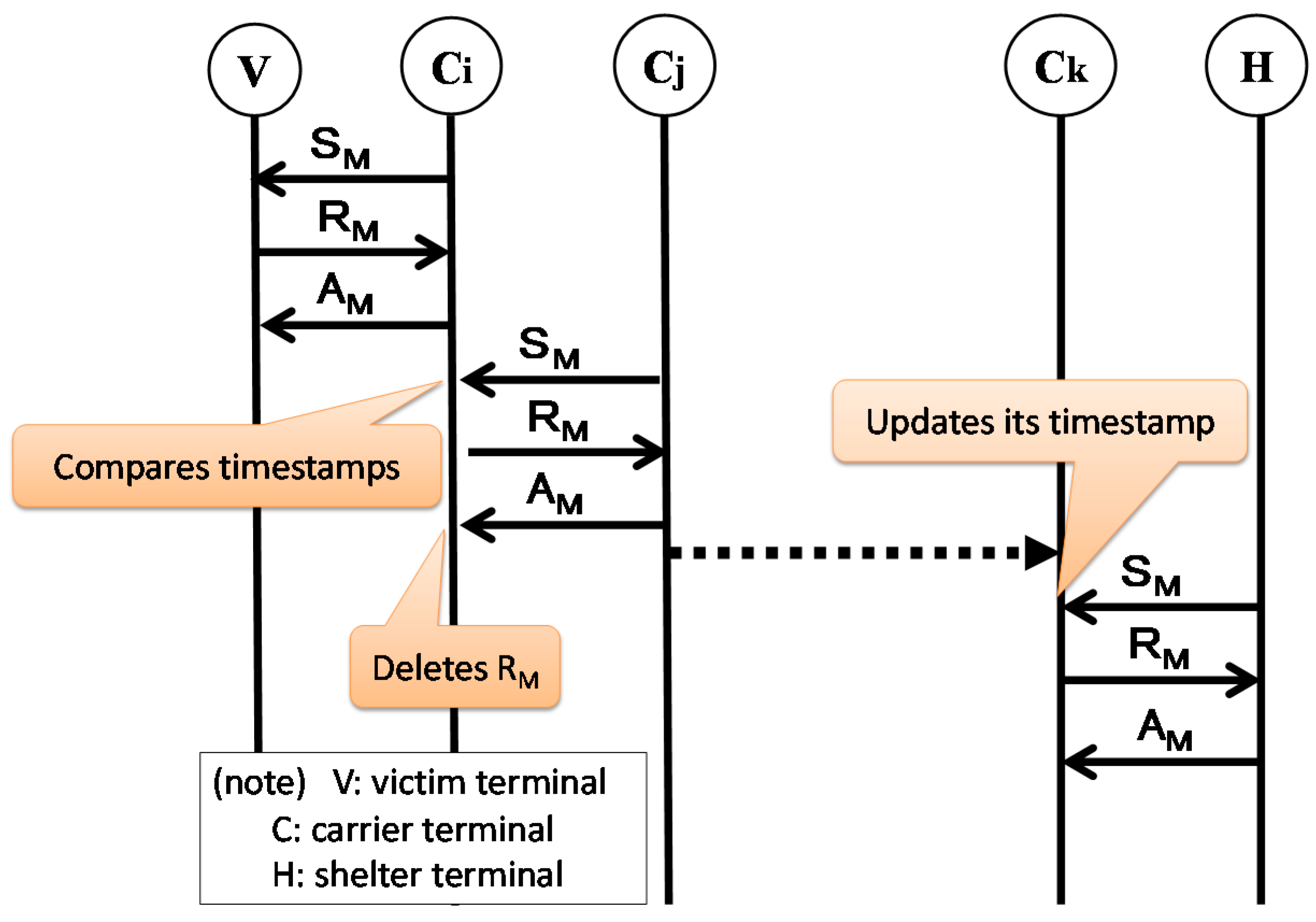
4.2. Receiver-Triggered Handshake Protocol

The receiver-triggered handshake protocol reflects the technical elements (1) to (6) discussed in Section 4.1. Each carrier terminal has its own carrier ID. Three types of bundle are exchanged: search message bundle (SM), response message bundle (RM), which contains safety confirmation information, and acknowledgement message bundle (AM). Only carrier terminals send SM. A carrier terminal sends SM every T seconds. A victim terminal that has received an SM sends back an RM to the sender. The following information is added to the header of an SM or an RM.
SM: stime and buf.
RM: carrierID, sendtime, and gps.
Stime contains the timestamp of the time when the carrier terminal concerned was connected to a shelter terminal the last time. Buf contains information about the current buffer usage. Sendtime contains the time when the victim terminal concerned sent RM. Gps contains information about the victim terminal’s current location.

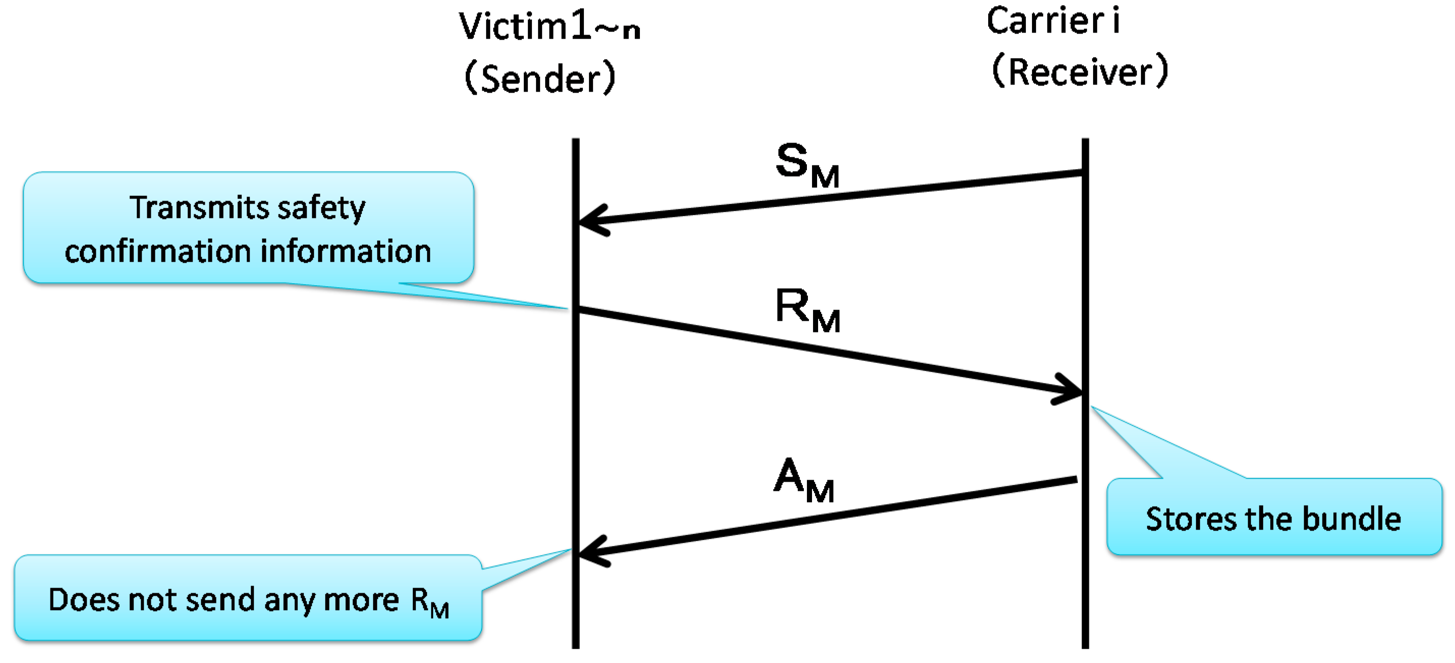
4.2.1. Communication between a Victim Terminal and a Carrier (or Shelter) Terminal

To incorporate (2) and (6) in Section 4.1, a victim terminal that sent an RM and has received an AM from a carrier terminal does not send any more bundles. If it has not received an AM, it attempts to send an RM to a carrier terminal to which it is next connected. The algorithm for communication between a victim terminal and a carrier terminal is as follows:
Step 1:
Carrier terminal, Ci, moves around the disaster area while transmitting SM every T seconds.
Step 2:
Victim terminal, V, receives an SM from Ci, and sends back an RM to Ci.
Step 3:
Ci receives the RM from V and sends back an AM.
Step 4:
4-1: If V receives the AM, go to Step 5.
4-2: If V receives no AM, go back to Step 1.
Step 5:
V does not send any more RM.
This communication sequence is shown in Figure 4.
Figure 4. Sequence of communication between a victim terminal and a carrier terminal.
Futureinternet 07 00152 g004

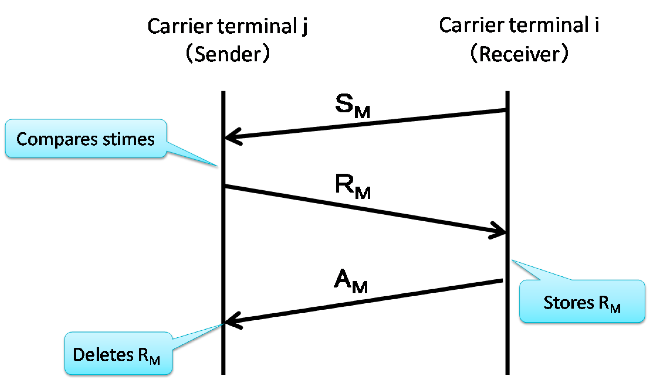
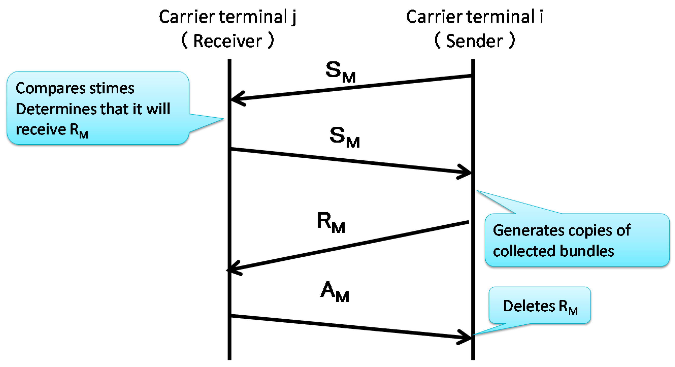
4.2.2. Inter-Carrier Terminal Communication

If a carrier terminal that has received information from victim terminals needs to go to a shelter and send the information to its shelter terminal, many carriers are needed to cover a wide disaster area. To reduce the number of carriers required, we allow a carrier to pass information to another carrier. Information may be relayed in many hops: for example, from a victim terminal to a carrier terminal to another carrier terminal and still another carrier terminal until the last carrier terminal sends information to a shelter terminal.
Since a carrier terminal collects bundles as it transmits an SM, it can determine whether another carrier terminal is nearby. Each of the two nearby carrier terminals receives an SM from each other, and based on SM received, determines which of them should receive information from the other terminal. An SM contains information about the time when the carrier terminal communicated with the shelter terminal the last time and the available storage capacity of the carrier terminal concerned. It would be reasonable to assume that the carrier terminal that accessed the shelter terminal later than the other terminal is closer to the shelter, and so it should receive information from the other terminal. However, a carrier terminal that is assumed to be close to a shelter may receive copies from many carrier terminals until its storage unit overflows. To avoid this, in determining whether a carrier terminal should receive or send information, it takes the available storage capacity of the carrier terminals concerned into consideration. The algorithm that incorporates the above and satisfies (3) and (5) in Section 4.1 is as follows:
Step 1:
Carrier terminal Cj transmits an SM.
Step 2:
Carrier terminal Ci transmits an SM.
Step 3:
Ci compares its stime with that of Cj.
Case 1: If stime of Ci < stime of Cj, go to Step 4-1.
Case 2: If stime of Ci > stime of Cj, go to Step 4-2.
Step 4:
4-1: Ci sends an RM to Cj.
4-2: Ci sends an SM to Cj, go to Step 2.
Step 5:
Cj sends back an AM.
Ci receives the AM from Cj and deletes the RM.
In this way, a bundle is relayed by multiple carrier terminals until it reaches a shelter terminal. The sequence of Cj sending copies to Ci (Step 4) is shown in Figure 5. The sequence of Ci sending copies to Cj (Step 5) is shown in Figure 6.
Figure 5. Sequence of inter-carrier terminal communication (from Cj to Ci).
Futureinternet 07 00152 g005
Figure 6. Sequence of inter-carrier terminal communication (from Ci to Cj).
Futureinternet 07 00152 g006

4.2.3. Communication between a Carrier Terminal and a Shelter Terminal

The algorithm for the communication between a carrier terminal and a shelter terminal is as follows:
Step 1:
Shelter terminal, H, transmits an SM every T seconds.
Step 2:
Carrier terminal, Ck, receives the SM, and sends back an RM, which contains collected safety confirmation information.
Step 3:
H sends back an AM.
Step 4:
Ck receives the AM from H and deletes the RM.
The sequence of communication from a victim terminal to a shelter terminal is shown in Figure 7.
Figure 7. Sequence of communication from a victim terminal to a shelter terminal.
Futureinternet 07 00152 g007

5. Construction of a Simulation Environment and Evaluation Conditions

This section describes the simulation environment used to evaluate the proposed protocol, evaluation conditions and the computation model used to estimate battery consumption.

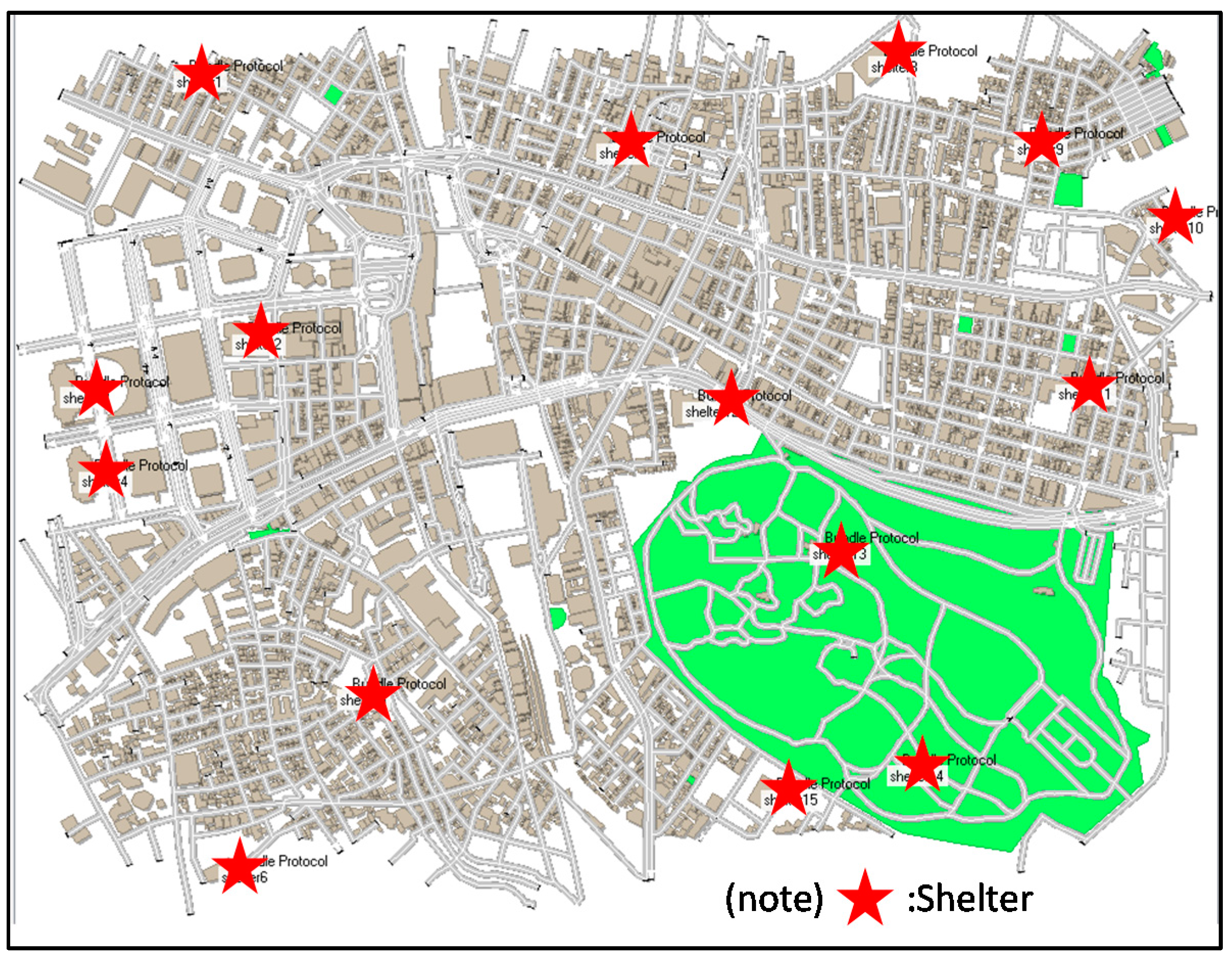
5.1. Construction of a Simulation Environment

We customized a network simulator, Scenargie [18], to simulate communication in DTN, and evaluated our proposed protocol and Epidemic Routing, Spray and Wait. We implemented the communication algorithm of the proposed protocol in the Base Simulator, and ran Multi-Agent Extension Module and Dot11 Module on it. The language used was C++, and the development environment was Visual Studio 2010.
Scenargie consists of four layers, from the physical layer to the application layer. In this simulation, IEEE802.11a was used for the physical layer and the data link layer. IPv4 was used for the network layer. For the transport layer, we used UDP for SM and AM, both of which are control bundles, and TCP for RM. Since the bundle protocol resides in the application layer in Scenargie, the proposed bundle protocol was implemented at the application layer.

5.2. Simulation Execution Environment Model and Simulation Conditions

The simulation execution environment was modeled on an actual area around Shinjuku Station (1.8 × 2.2 km2) in Tokyo. The map of the area was imported into Scenargie. The time simulated was one hour. It was assumed that victims who can walk go to the shelter on their own. Therefore, the simulation focused on those victims who did not walk to the shelter (because they walked to parks that were not designated as shelters, were confined in buildings, or were injured, etc.). The number of victim terminals was 1000. The number of rescuers was assumed to be 300 to 350. This number was determined from the density of the members of the Self Defense Forces [2] who were actually dispatched to Miyagi Prefecture at the time of the Great East Japan Earthquake. Since it is likely that rescuers operate in a team, we assumed that 10 members made up a team and a carrier terminal was allocated to each team. Thus, we placed 30 carrier terminals. The number of shelters was 15. This number was determined from the number of actual places that can be used as shelters. Carriers start at a shelter, and walk to another shelter looking for victims. The moving speed of carriers was determined assuming that they may, from time to time, stop awhile for rescue operations. The storage capacity of a carrier terminal was 10 MB. The size of a safety confirmation message sent by a victim terminal was assumed to be 100 Bytes. The storage capacity of an information carrier terminal is much smaller than the storage capacity of an actual mobile terminal. This small capacity was selected because we took the simulation execution environment into consideration. It is not meant to restrict the propose protocol. The size of a safety confirmation message was selected assuming that it was a simple text message. In selecting these values, we intended to minimize the power needed for exchange of messages because, for a victim, the remaining battery power of his/her terminal is precious. These simulation conditions are shown in Table 3. The simulation execution environment is shown in Figure 8. The initial locations of terminals other than shelter terminals were random.
Table 3. Simulation conditions.
ItemValueItemValue
SimulatorScenargie 1.8Moving speedVictim: 0 m/s
Carrier: 0–3 m/s
Execution time1 hourMobility of victimsStanding still
EnvironmentAround Shinjuku station
(1.8 × 2.2 km2)
Mobility of carriersRandom waypoint
Number of victim terminals100Maximum communication distanceAbout 80 m
Number of carrier terminals30Number of simulation attempts10
Number of shelters15Storage capacity of a carrier terminal10 MB
Wireless communication methodIEEE802.11aMessage size100 Bytes

5.3. Calculation of Battery Consumption

Following a disaster, there will be a power outage, and the batteries of mobile terminals cannot be recharged. Therefore, the proposed protocol minimizes the number of bundles a victim terminal sends to only one. As a result, battery consumption of a victim terminal is much lower than that needed in Epidemic Routing. Our calculation of battery consumption is based on a model given in [19]. It is assumed that batteries of carrier terminals can be recharged. Therefore, we focus on battery consumption of victim terminals only.
Figure 8. Simulation execution environment modeled on an area around Shinjuku Station.
Futureinternet 07 00152 g008
While the power consumption model in a MANET proposed in [19] includes the consumption of power needed for routing control, in our proposed protocol, a victim terminal, which does not need to relay bundles, consumes power only when it receives SM and AM and sends RM. The power consumed when a victim terminal sends a bundle can be expressed as:
P send = b controlrecv + m send × (length of bundle) + b send
where bcontrolrecv is power consumed when a victim terminal receives an SM and AM from a carrier terminal, msend is the power consumed when a victim terminal sends one Byte of bundle, and bsend is the basic power consumption needed when a victim terminal sends a bundle. The constants used in the calculation of power consumption are shown in Table 4.
Table 4. Constants used in the calculation of power consumption.
ParameterValue
bcontrolrecv120 mW·s
msend1.89 mW·s/byte
bsend246 mW·s
The constants shown in Table 4 are based on the measured values presented in [19]. Power consumption was calculated by applying data obtained in the simulation to Equation (1).

6. Evaluation

We compared the proposed protocol with Epidemic Routing, Spray and Wait (number of copies: 10), and Spray and Wait (number of copies: 5) using simulation. We ensured that victim terminals did not become relay nodes even in Epidemic Routing or Spray and Wait. At the beginning of simulation, each victim terminal is fully charged to its battery capacity of 1810 mAh, which is the battery capacity of iPhone 6. As a simulation proceeds, the battery charge is consumed. When the battery can no longer supply enough power for communication, the victim terminal concerned ceases to communicate.

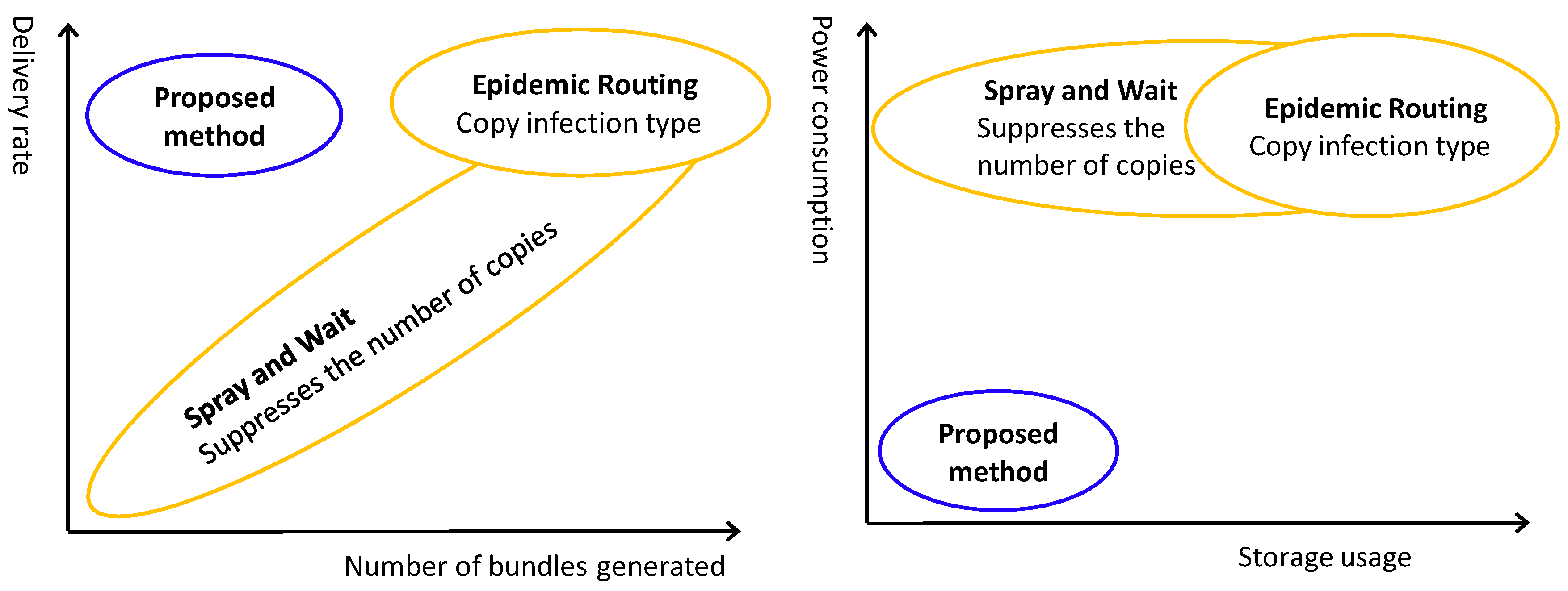
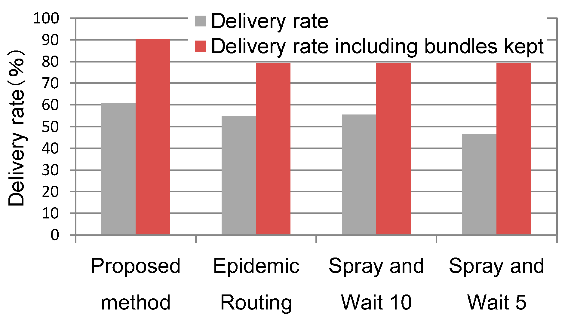
6.1. Bundle Delivery Rate

The simulation result for delivery rate is shown in Figure 9. By “delivery rate including bundles kept” in this figure is meant that “delivered bundles” assumed in this delivery rate include those bundles that carrier terminals received from victim terminals but did not yet deliver to shelters before the simulation ended. This is conceived because we can assume that, even when carrier terminals are not able to deliver these bundles to shelters before the end of the simulation execution time of one hour, they eventually will.
Figure 9. Delivery rate (rate at which bundles are delivered to shelters).
Futureinternet 07 00152 g009
The figure shows that the proposed method records a higher delivery rate than other existing methods. The reason is as follows. If battery consumption is not taken into consideration, the existing methods yield a higher delivery rate than the proposed method but when battery consumption is taken into consideration, batteries of victim terminals often run out and become unable to send safety confirmation information. In contrast, in our proposed method, the batteries of victim terminals continue to have enough charge to send bundles until the end of the one-hour simulation.

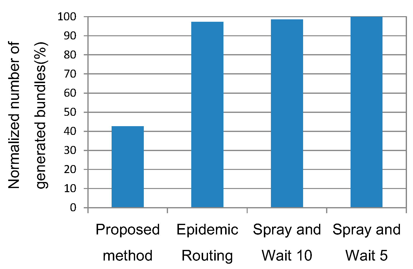
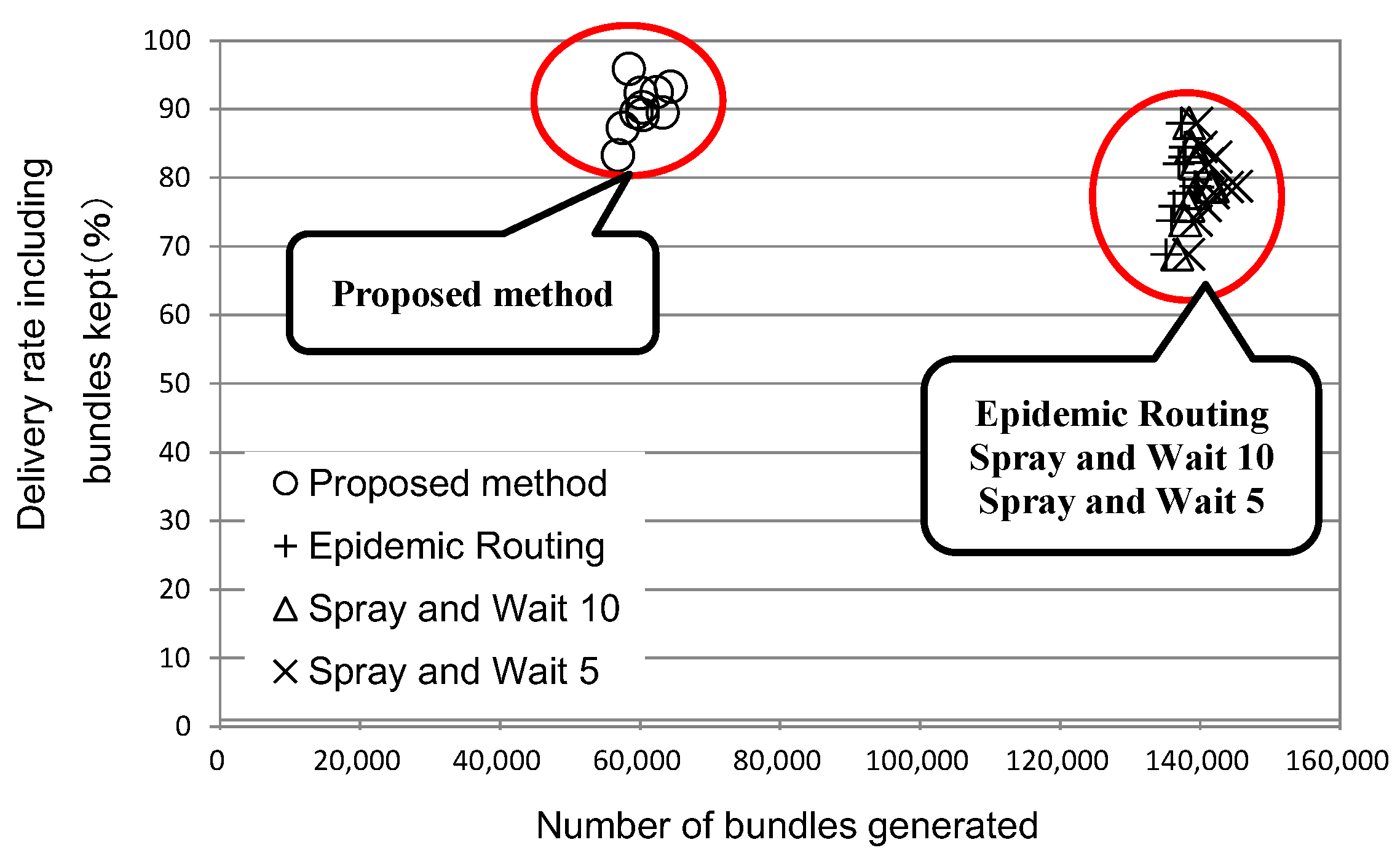
6.2. Total Number of Bundles Generated in the Network

Figure 10 compares the different methods in terms of the total number of bundles generated in the network. The number of bundles generated in Spray and Wait (number of copies: 5), which generates the largest number of bundles, is normalized to 100%. The number of bundles generated by the proposed method is about 40% of that of any existing method. Based on this result and the result shown in Figure 9, we can conclude that the proposed method is the most efficient method of delivering data to shelter terminals. The reason why Spray and Wait (number of copies: 5) generates more bundles than Epidemic Routing is that Spray and Wait enables victim terminals to continue to send hello messages over a longer time than Epidemic Routing, which causes batteries of victim terminals to run out quickly.
In the proposed method, victim terminals start communication only when it receives an SM from a carrier terminal. Therefore, the number of bundles generated is proportional to the number of carrier terminals. This is why the proposed method generates fewer bundles than the other methods.
Figure 10. Normalized number of generated bundles where the number of bundles generated by Spray and Wait (number of copies: 5) is normalized to 100%.
Futureinternet 07 00152 g010

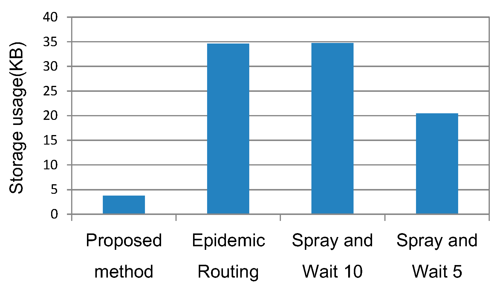
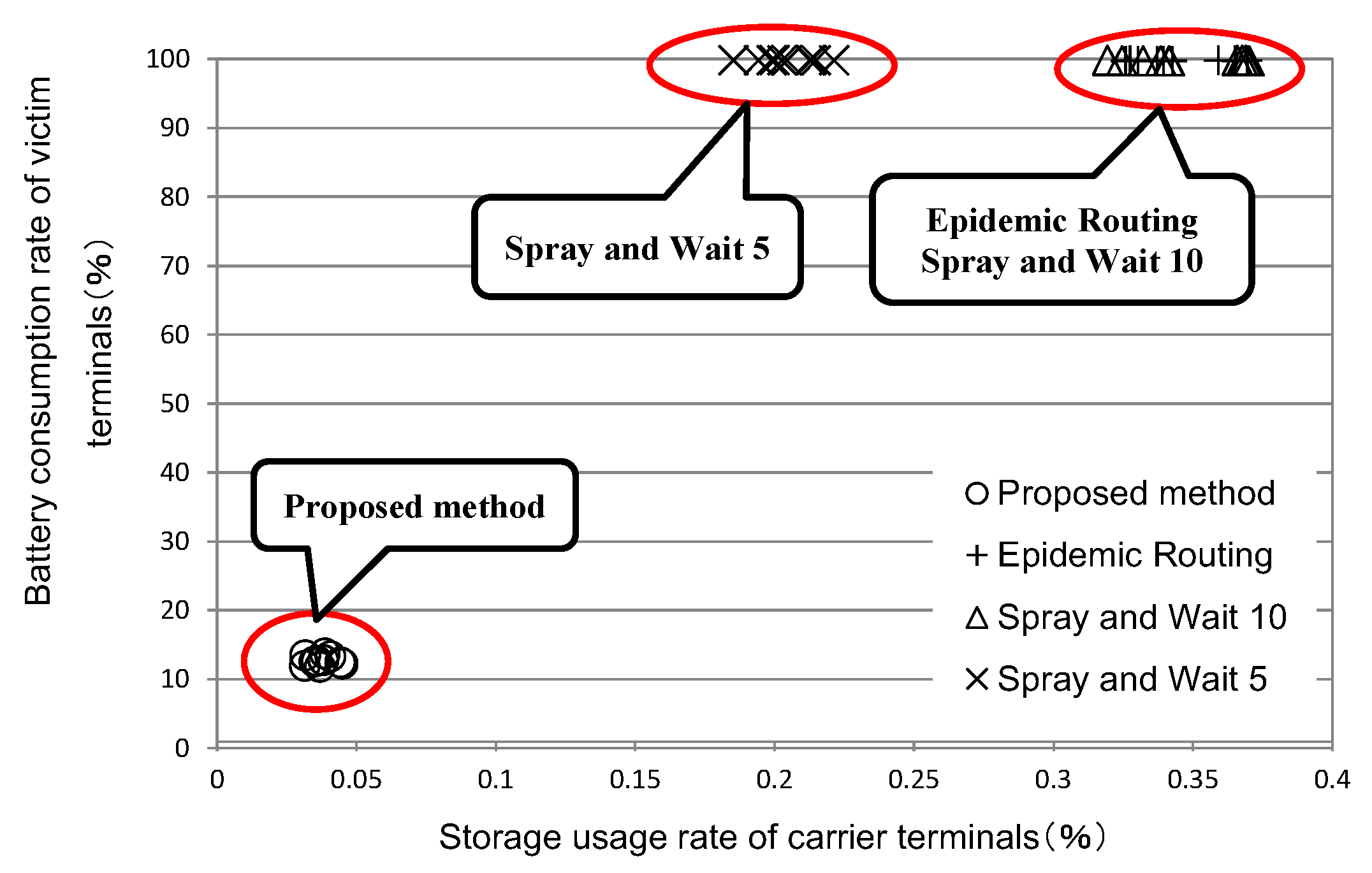
6.3. Maximum Storage Usage of Carrier Terminals

The simulation result of storage usages of carrier terminals is shown in Figure 11. Since the size of bundle data is 100 Bytes, the maximum storage usage is below 60 KB in any method. The storage usage of Spray and Wait (number of copies: 5) is considerably smaller than Epidemic Routing or Spray and Wait (number of copies: 10). In the case of the proposed protocol, the storage usage is about 5 KB, which is far smaller than that of Epidemic Routing or Spray and Wait.
Figure 11. Average maximum storage usage of carrier terminals.
Futureinternet 07 00152 g011

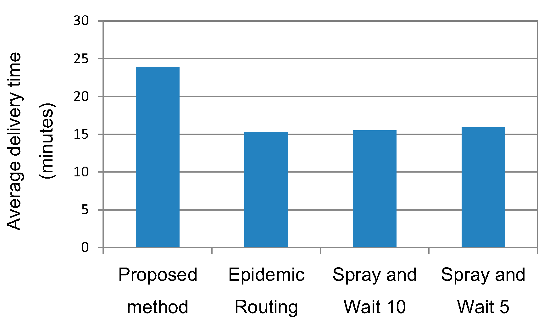
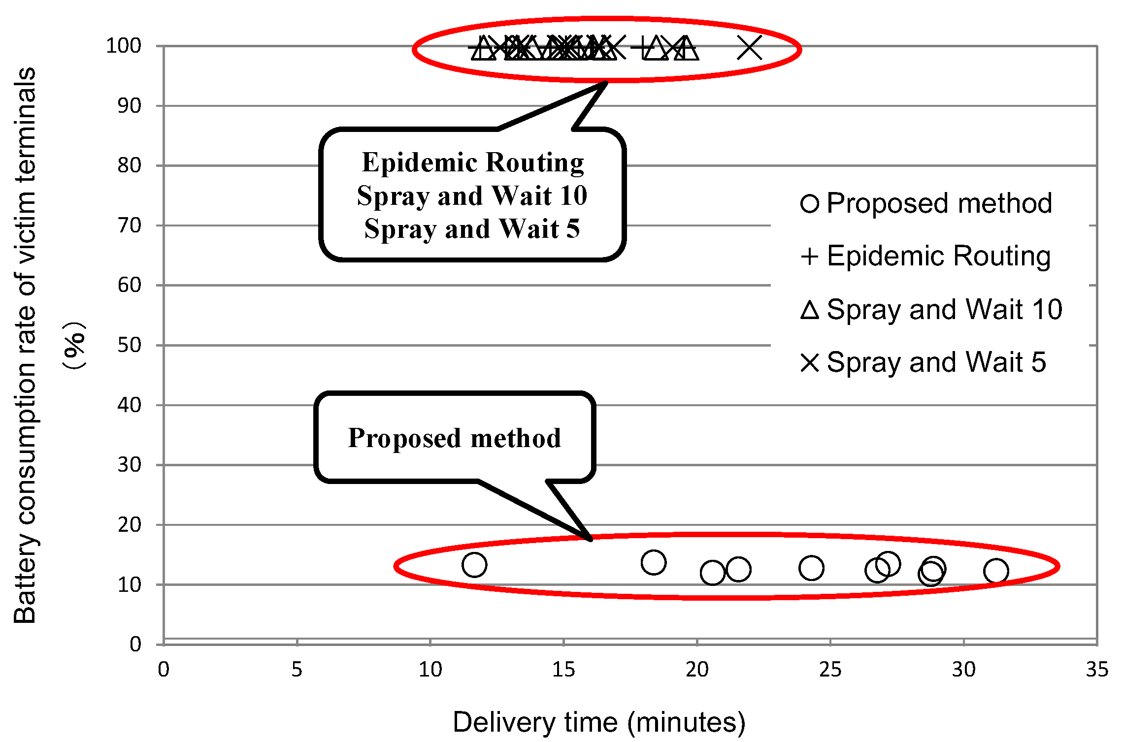
6.4. Average Delivery Time

The average time it takes for bundles containing safety confirmation information to be delivered to a shelter terminal (delivery time) is shown in Figure 12. The delivery time of the proposed method is the longest. This depends on the speed of carriers, the number of carriers, and the number of copies made in victim terminals. The number of carrier terminals is 30. If the number of carriers or the speed of carriers is increased, the delivery time will be reduced. The number of copies made in each victim terminal is one. If this number is increased, the delivery time will become shorter. In the proposed method, when two carrier terminals communicate with each other, the one that communicated with a shelter terminal later receives an RM from the other. In other words, the decision as to which carrier terminal should receive bundles from the other depended on their timestamps. However, even if carrier terminal B is closer to a shelter than carrier terminal A, B may be going away from a shelter terminal. After B receives RM from A, it keeps it as it travels around the disaster area until it goes to a shelter terminal. This can take a long time. It will be necessary to study the criteria used to determine which of the pair of communicating carrier terminals should be entrusted with keeping RM.
Figure 12. Average delivery time.
Futureinternet 07 00152 g012

6.5. Overall Evaluation

The results described in Section 6.1, Section 6.2, Section 6.3 and Section 6.4 are presented from different perspectives in Figure 13, Figure 14 and Figure 15. The battery consumption rate of victim terminals and the storage usage of carrier terminals are shown in Figure 13. In the existing methods, even if the batteries of victim terminals are fully charged when a disaster occurred, they run out within one hour, rendering these terminals unusable. Both Epidemic Routing and Spray and Wait take up considerable storage capacities of carrier terminals. The proposed method is free from these problems. Thus, the objective shown in Figure 3 is achieved.
Figure 13. Battery consumption rate of victim terminals and the storage usage of carrier terminals in each method.
Futureinternet 07 00152 g013
Figure 14. Delivery rate including bundles kept and the number of bundles generated.
Futureinternet 07 00152 g014
Figure 15. Battery consumption rate of victim terminals and delivery time.
Futureinternet 07 00152 g015
The delivery rate including bundles kept and the number of bundles generated in the network are shown in Figure 14. The delivery rate including bundles kept of the existing methods is lower than that of the proposed method in spite of the fact that the existing methods generate a larger number of bundles. Thus, the proposed method is superior to the existing methods in terms of the delivery rate including bundles kept and the number of bundles generated. Again, the objective shown in Figure 3 is achieved.
The battery consumption rate of victim terminals and delivery time are shown in Figure 15. As was mentioned above, the proposed method is superior to Epidemic Routing or Spray and Wait in terms of battery consumption, storage usage, the number of bundles generated, and delivery rate with bundles kept. However, it has a problem with delivery time, which is more varied and is often longer than the other methods. This is an area where the proposed method has room for improvement.

7. Conclusions and Future Issues

As a means of sending information about the safety of victims (safety confirmation information) in a disaster, this paper has proposed delay/disruption tolerant networks (DTN) that uses a receiver-triggered handshake method, and has presented the detailed protocol of this method. The primary objective of this method is to reduce batter consumption of the mobile terminals of victims. The proposed protocol was implemented on a network simulator, and simulations were conducted for a disaster area that was modeled on an area around Shinjuku Station in Tokyo. Victims were randomly distributed in the area. The proposed method has been compared with Epidemic Routing and Spray and Wait, which are representative routing methods for DTN. The simulation results showed that the probability at which safety confirmation information reaches a shelter is, more or less, the same for all the three methods, but that the proposed method is superior to the other existing methods in terms of battery consumption of victim terminals, storage usage of carrier terminals, and the number of bundles generated in the network. However, the proposed method takes a longer time for safety confirmation information to reach a shelter (delivery time) than the other methods.
As the future issues, to determine the application area of the proposed protocol more precisely, it will be necessary to conduct simulation under more varied conditions. For example, a safety confirmation message can be larger if we consider the inclusion of images and videos in it. It is also necessary to consider a larger storage capacity for an information carrier terminal. Also, the proposed protocol has room for improvement in delivery time. We will study potential means of shortening delivery time, such as adjusting the number of copies made by victim terminals and revising the method of determining which of the two carrier terminals that begin to communicate with each other should receive safety confirmation information. Furthermore, in a major disaster, the number of information carriers will be far smaller than that of victims, making it difficult to collect safety confirmation information rapidly. A solution can be to enlist those victims who can walk to shelters as information carriers. To evaluate this solution, it will be necessary to add the relevant functions to the proposed system.

Author Contributions

R. Yamashita contributed to the design of the proposed scheme, the software prototype of evaluation system, the evaluation data collection, writing of the primary draft of the paper. K. Takami instructed his research activities, and then contributed to refinement of the proposed scheme, the evaluation result, and the advancement of the paper.

Conflicts of Interest

The authors declare no conflict of interest.

References

  1. White Paper 2011 Information & Communications in Japan, Part 1, Section 1. Available online: http://www.soumu.go.jp/johotsusintokei/whitepaper/eng/WP2011/2011-index.html (accessed on 9 March 2015).
  2. White Paper 2011 Information & Communications in Japan, Part 1, Chapter 3. Available online: http://www.soumu.go.jp/johotsusintokei/whitepaper/eng/WP2012/2012-index.html (accessed on 9 March 2015).
  3. Warthman, F. Delay Tolerant Networks (DTNs)—A Tutorial Version 2.0. Warthman Associates, Based on Technology Developed by the Interplanetary Internet Special Interest Group. 23 July 2012. Available online: http://ipnsig.org/wp-content/uploads/2012/07/DTN_Tutorial_v2.04.pdf (accessed on 10 March 2015).
  4. Vahdat, A.; Becker, D. Epidemic Routing for Partially-Connected Ad Hoc Networks; Duke Technical Report, CS-2000-6; Department of Computer Science Duke University: Durham, NC, USA, 2000. [Google Scholar]
  5. Spyropoulos, T.; Psounis, K.; Raghavendra, C.S. Spray and Wait: An Efficient Routing Scheme for Intermittently Connected Mobile Networks. In Proceedings of the SIGCOMM’05 Workshops, Philadelphia, PA, USA, 22–26 August 2005.
  6. Akiyama, Y.; Kobayashi, A. A Protocol and the Prototype to communicate with a communication blackout region based on DTN architecture. In Proceedings of the Forum on Information Technology (FIT) 2012, Koganei-shi, Tokyo, Japan, 4–6 September 2012; pp. 149–156.
  7. Takemoto, H.; Zamora, F.L.J.; Kashihara, S.; Taenaka, Y.; Mineo, T.; Kanada, S.; Yamaguchi, S. Evaluation of information-Sharing Method among Disaster Victims in A Collapsed Communication Service Area; IEICE Tech. Rep., MoNA2013-43; The Institute of Electronics, Information and Communication Engineering (IEICE): Tokyo, Japan, November 2013; pp. 11–16. [Google Scholar]
  8. Sawamura, Y.; Teranishi, Y.; Takeuchi, S.; Harumoto, K.; Nishio, S. An Efficient Broadcast Method Based on Estimation and Preservation of Stable Links in Delay Tolerant Networks. In Proceedings of the IPSJ, Multimedia, Distributed, Cooperative, and Mobile Symposium 2011 (DICOMO2011), Miyazu-shi, Kyoto, Japan, 6–8 July 2011; pp. 1121–1129.
  9. Sun, W.; Kitani, T.; Shimata, N.; Yasumoto, K. A Data Gathering and Sharing Proposal for Disaster Relief based on DTN; Information Processing Society of Japan (IPSJ) SIG Technical Report; IPSJ: Tokyo, Japan, February 2009; pp. 61–66. [Google Scholar]
  10. Koyama, Y.; Mizumoto, T.; Imazu, S.; Yasumoto, K. Safety Confirmation System with DTN-based Message Routing in 3G Disabled Areas Caused by Large-Scale Disaster; IEICE Tech. Rep., MoMuC 122(44); The Institute of Electronics, Information and Communication Engineering (IEICE): Tokyo, Japan, May 2012; pp. 171–177. [Google Scholar]
  11. Chuah, C.M.; Ma, W. Integrated Buffer and Route Management in a DTN with Message Ferry. In Proceedings of the IEEE Military Communications Conference (MILCOM) 2006, Washington, DC, USA, 23–25 October 2006; pp. 1–7.
  12. Abe, R.; Nakamura, Y.; Shiraishi, Y.; Takahashi, O. An Effective DTN Routing Scheme using Message Ferries. In Proceedings of the IPSJ, Multimedia, Distributed, Cooperative, and Mobile Symposium 2012 (DICOMO2012), Kaga-shi, Ishikawa, Japan, 4–6 July 2012; pp. 1686–1696.
  13. Tariq, B.M.M.; Ammar, M.; Zegura, E. Message Ferry Route Design for Sparse Ad hoc Networks with Mobile Nodes. In Proceedings of the MobiHoc’06, Florence, Italy, 22–25 May 2006.
  14. Wentui, Z.; Ammar, H.M. Message Ferrying: Proactive Routing in Highly-partitioned Wireless Ad Hoc. In Proceedings of the Ninth IEEE Workshop on Future Trends of Distributed Computing Systems (FTDCS’03), San Juan, Puerto Rico, 28–30 May 2003; pp. 308–314.
  15. Seino, W.; Yoshihisa, T.; Hara, T.; Nishio, S. A Communication Traffic Reduction Method by Delivering Predicted Values on Sensor Data Collection with a Mobile Sink. In Proceedings of the IPSJ, Multimedia, Distributed, Cooperative, and Mobile Symposium 2011 (DICOMO2011), Miyazu-shi, Kyoto, Japan, 6–8 June 2011; pp. 1175–1182.
  16. Yoshihisa, T.; Nishio, S. Communication Methods for Sensor Database Construction by Rounding Sink Considering Amount of Data Collection. DBSJ J. 2010, 8, 13–18. [Google Scholar]
  17. Nakamiya, M.; Kishino, Y.; Terada, T.; Nishio, S. Route Planning Method for Multi Mobile Sensor Nodes. Inf. Process. Soc. Jpn. (IPSJ) J. 2009, 50, 1262–1271. [Google Scholar]
  18. Scenargie. Space-Time Engineering. Available online: https://www.spacetime-eng.com/en/index.html (accessed on 9 March 2015).
  19. Feeney, M.L. An Energy-Consumption Model for Performance Analysis of Routing Protocols for Mobile Ad Hoc Networks. ACM/Kluwer Mob. Netw. Appl. (MONET) 2001, 6, 239–249. [Google Scholar] [CrossRef]

