1. Introduction
Path planning plays a crucial role in Industrial Internet of Things (IIoT) applications, where autonomous systems must navigate complex environments while maintaining high operational efficiency and safety standards [
1,
2,
3].
Typical implementations include: (1) Unmanned Aerial Vehicles (UAVs) performing inspection and monitoring tasks in complex facilities [
4,
5,
6,
7], (2) Automated Guided Vehicles (AGVs) navigating structured 3D spaces such as warehouses [
8,
9,
10,
11], and (3) Industrial robotic arms executing precision tasks in collaborative workspaces [
12,
13,
14]. The primary challenge lies in dynamically avoiding obstacles while optimizing path quality under multiple constraints, including spatial limitations and real-time computational demands [
15,
16,
17,
18].
Beyond these established applications, path planning is increasingly critical in more complex and collaborative autonomous systems. For instance, multi-UGV formation cooperative reconnaissance for defense tasks, where patrol strategies are inspired by human behaviors [
19]. UAVs operating under terrain limitations require advanced perception capabilities for visual tracking, geolocation, and inter-platform data transmission [
20]. Moreover, recent research proposes novel 3D path planning methods, including enhanced dynamic artificial potential field (ED-APF) techniques, to enable UAV–MGV cooperation and adaptive reconnaissance trajectories [
21]. These advanced applications impose even more stringent requirements on path planning algorithms, including scalability to multi-agent systems, resilience to uncertainty, and the ability to generate efficient trajectories in deeply complex environments.
Compared to 2D planning, 3D path planning introduces additional complexity from altitude constraints in aerial navigation, volumetric obstacle avoidance, spatial limitations, and the need for smooth, collision-free trajectories [
22,
23,
24]. While conventional approaches (e.g., A, RRT) are widely used in UAV navigation and robotic systems [
25,
26,
27], they exhibit critical limitations when applied to complex 3D scenarios. Specifically, they often struggle with: (1) exponentially expanded search spaces due to 3D obstacle distributions; and (2) limited adaptability in dynamic or uncertain environments [
28,
29,
30,
31].
In addition to computational challenges, recent studies emphasize system-level factors that directly shape UAV path planning requirements. Excessive curvature, torsion, or sudden trajectory changes can violate UAV dynamic stability limits [
32], motivating the use of smoothness constraints such as B-splines to ensure controllability. Moreover, damping properties of sustainable UAV materials may influence allowable maneuver accelerations [
33], linking material characteristics to safe and reliable trajectory design.
Particle Swarm Optimization (PSO) has been widely studied for path planning; however, standard implementations suffer from issues such as premature convergence and insufficient avoidance of poor local optima [
34,
35,
36]. To address these limitations, we propose an enhanced PSO algorithm featuring three key innovations:
Logistic chaotic initialization that ensures population diversity.
Adaptive dynamic learning factors that automatically balance exploration and exploitation.
Nonlinear inertia weights enabling stage-specific convergence control.
Comparative experimental results demonstrate consistent enhancements across multiple performance dimensions—including path length reduction and computational efficiency—relative to conventional methods.
The proposed method is relevant for Industrial Internet of Things (IIoT) applications that demand real-time responsiveness, with potential extensions to multi-agent systems and edge computing architectures.
2. Related Works
In the field of 3D path planning research, the evolution of various algorithms has consistently focused on addressing the core challenge of achieving efficient and secure pathfinding in complex environments. Traditional approaches like the A* algorithm demonstrate exceptional performance in structured environments through heuristic search [
37,
38]. At the same time, Rapidly-exploring Random Trees (RRTs)-based methods prove more effective for path exploration in high-dimensional spaces [
39,
40]. Although these methods perform well in specific scenarios, they often struggle to simultaneously satisfy requirements for path quality, real-time performance, and multiple constraints when confronted with complex 3D terrains.
Recent advances in intelligent optimization algorithms have introduced new approaches to three-dimensional path planning. The integration of neural networks with Particle Swarm Optimization (PSO) in [
41] demonstrated improved path planning performance, though its heavy reliance on high-dimensional encoding substantially increased algorithmic complexity and implementation challenges. Hybrid intelligent algorithms combining standard PSO with other swarm intelligence techniques, as proposed in [
42,
43], enhanced local search capabilities but required significantly more iterations and exhibited slower convergence rates, resulting in increased computational overhead.
Studies employing chaos theory to modify pheromone update mechanisms [
44,
45] achieved notable improvements in global search capabilities and path smoothness; however, the failure to optimize initial pheromone concentrations led to considerable computational redundancy and reduced convergence speed, ultimately limiting practical applicability. While the modified Ant Colony Optimization (ACO) algorithm in [
46,
47] showed improved convergence speed and optimization capabilities, it remained prone to local optima in complex 3D environments, adversely affecting path planning outcomes.
The introduction of chasing behavior from the Artificial Fish Swarm algorithm (AFSA) in [
48] significantly reduced search time, and the incorporation of crowding distance operators with multi-objective optimization methods in [
49] generated diversified Pareto-optimal solution sets. However, both approaches were primarily designed for two-dimensional path optimization and showed limited effectiveness when applied to complex 3D terrains. Although artificial potential field methods [
50] successfully enabled UAV path planning with obstacle avoidance, they frequently converged to local optima when targets were proximate to obstacles. Similarly, the terrain-aware PSO variant in [
51], which incorporated elevation variations and radar threat modeling, still exhibited insufficient precision and convergence speed for practical applications. Despite demonstrating feasibility in 3D environments, the algorithms in [
50,
51] consistently faced challenges with local optima convergence and solution accuracy.
Building on these foundations, recent years (2023–2025) have witnessed a series of hybrid PSO-based UAV path planning approaches that integrate swarm intelligence with auxiliary mechanisms such as chaotic mapping, adaptive learning, and hybrid operators. Representative examples are summarized in
Table 1, which contrasts IPSO with state-of-the-art PSO-based methods in terms of algorithmic structure, complexity, and reported performance.
In summary, existing 3D path planning algorithms still exhibit significant limitations in complex environments, particularly regarding real-time performance and computational efficiency. The Improved Particle Swarm Optimization algorithm (IPSO) proposed in this work addresses these challenges through three key innovations: (1) Logistic chaotic mapping for enhanced population diversity; (2) Dynamic learning factors enabling adaptive exploration–exploitation balance; and (3) Nonlinear inertia weights optimizing convergence characteristics. Collectively, these enhancements achieve a 14.4% reduction in path length and 65.0% improvement in computational efficiency compared to conventional algorithms, delivering an efficient, reliable solution for real-time path planning in complex 3D environments.
3. Problem Formulation
3.1. Three-Dimensional Path Planning Problem Description
The core objective of 3D path planning is to identify an optimal trajectory while avoiding obstacles in complex environments. To realistically simulate such environments, this study constructs mountainous terrain and benchmark topography [
55] as obstacle representations. The benchmark terrain model characterizes fundamental undulations of the landscape through Equation (1):
where
and
represent the projected coordinates of the model on the XOY plane; and
denotes the elevation value corresponding to the horizontal plane point. The constant coefficients
,
,
,
,
,
, and
are used to control the undulation characteristics of the benchmark terrain in the digital map.
To more realistically simulate natural environments, this paper employs an exponential function to characterize natural mountain features, with the mathematical model expressed by Equation (2):
where the following are expressed:
represents the elevation of the mountain terrain;
denotes the total number of mountain peaks;
indicates the 2D planar coordinates;
) specifies the center coordinates of the -th peak;
serves as the terrain parameter controlling peak height;
and are the attenuation coefficients for the -th peak along the x- and y-axes. These coefficients govern the slope steepness.
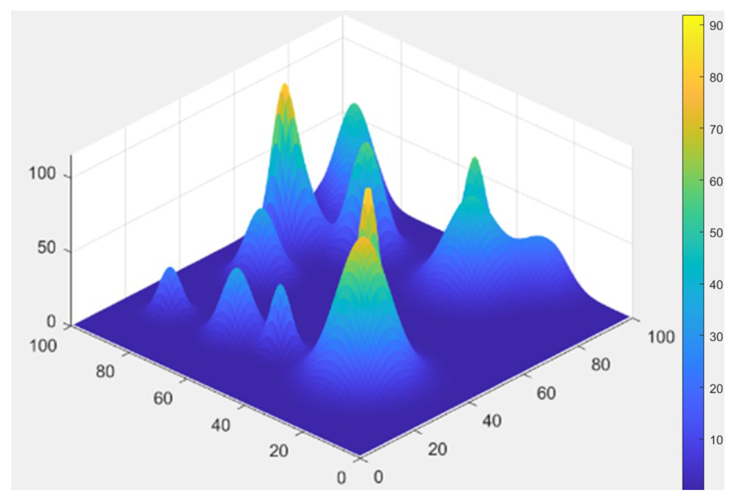
Based on this model, we constructed a 100 m × 100 m × 100 m 3D spatial environment with 15 randomly generated mountain features, as illustrated in
Figure 1. This modeling approach effectively simulates complex 3D environments and provides a reliable experimental scenario for validating path planning algorithms.
The model effectively simulates complex three-dimensional environments, providing a reliable experimental scenario for validating path planning algorithms, and suitable for real-time path planning in edge intelligence applications.
3.2. B-Spline Based 3D Path Parameterization Method
When planning 3D paths in complex terrain environments, trajectory smoothness directly impacts stability and energy efficiency. As shown in
Figure 1, the 3D terrain model contains multiple mountain obstacles where traditional straight-line connections would cause abrupt curvature changes, failing to meet the kinematic constraints of typical autonomous agents (e.g., UAVs, AGVs).
To address this, we employed parametric cubic uniform B-splines for smooth waypoint interpolation. The method’s local support property (where each curve segment is influenced only by adjacent control points) and C
2 continuity (ensuring curvature continuity) effectively balance path smoothness with computational efficiency, making it suitable for various 3D path planning requirements [
29,
30].
3.2.1. Path Smoothness Constraints
The quality of spatial curves is determined by two differential geometric characteristics: curvature and torsion.
Quantifies the local bending degree of a curve, defined as the rate of change in the tangent vector angle with respect to arc length, given by Equation (3):
where
represents the parametric equation of the curve. For planar trajectories, the torsion is identically zero (
τ ≡ 0).
- 2.
Torsion (τ)
Torsion quantitatively describes the spatial twisting behavior of 3D curves, defined as the rate of change in the binormal vector angle with respect to arc length, given by Equation (4):
For strictly 2D trajectories, the torsion remains identically zero.
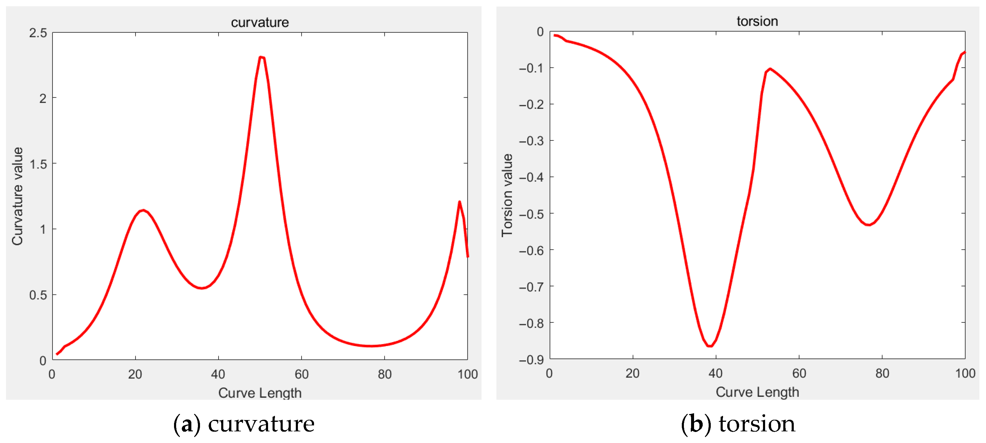
In three-dimensional space, path smoothness requires both curvature and torsion to remain continuous without abrupt changes. The B-spline formulation inherently ensures continuous variation in curvature and torsion through its control points, effectively eliminating path discontinuities (see
Figure 2).
3.2.2. B-Spline Parametric Implementation
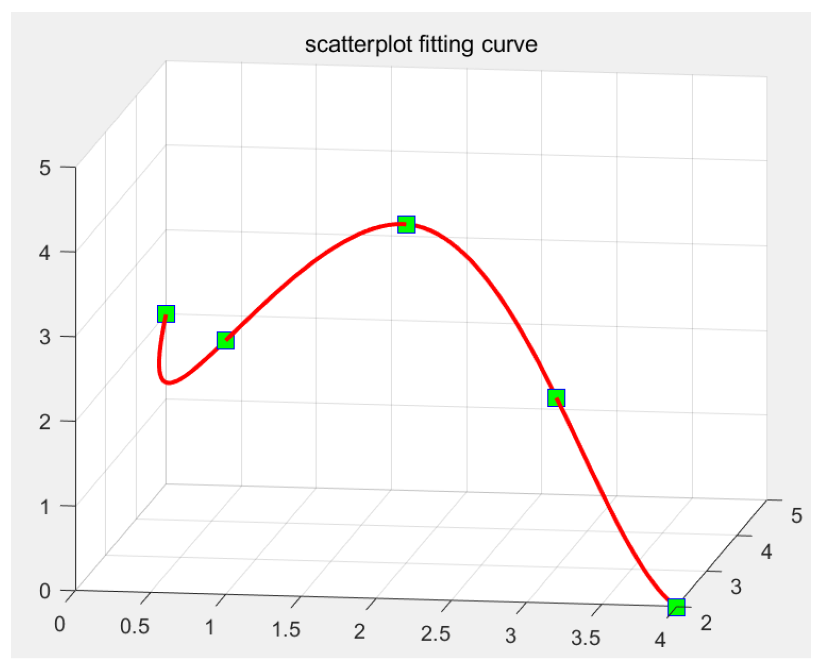
Although increasing the number of waypoints may improve path fitting accuracy, it has a negligible impact on the algorithm’s performance. To streamline the fitting process, this study selects five key waypoints to construct the spatial path: a start point, an end point, and three intermediate waypoints.
- 2.
Control Point Optimization
The MATLAB (version R2021a) spaps function is then employed to perform smooth fitting, converting the waypoints into B-spline control points. This function automatically balances:
The final trajectory is generated as a linear combination of the control points, achieving smooth interpolation between the 3D waypoints (see
Figure 3).
3.3. Objective Function Design
In UAV path planning, the design of the objective function requires comprehensive consideration of factors including trajectory cost, flight safety, and boundary constraints.
3.3.1. Trajectory Cost
The trajectory cost refers to the total path distance from the starting node to the destination. Given a path consisting of n nodes, the path distance is calculated using Equation (5):
where
represents the UAV’s cumulative trajectory cost;
specifies the total number of discretized path nodes;
denotes the Euclidean distance between node and node .
3.3.2. Terrain Cost
To ensure flight safety, the UAV must avoid collisions with obstacles. A collision is considered to occur when the UAV’s flight altitude is lower than the current obstacle height. Accordingly, a collision coefficient with a significantly large value is established to substantially increase the collision penalty. The terrain cost is defined by Equation (6):
where
denotes the terrain cost;
represents the collision coefficient;
indicates the flight altitude at the -th node;
refers to the obstacle height at the -th node location;
represents that the UAV has collided with an obstacle.
3.3.3. Boundary Cost
To ensure the UAV operates within prescribed flight boundaries, a boundary cost coefficient
is implemented. When the UAV’s position exceeds the defined operational limits,
adopts a significantly large value to enforce spatial constraints. The boundary cost is formulated in Equation (7):
where
represents the boundary cost;
denotes the boundary penalty coefficient;
, , indicate the UAV’s 3D positional coordinates at the -th waypoint;
, , specify the maximum allowable flight range along each axis.
The objective function is suitable for real-time path planning in edge-intelligent environments, and can effectively balance path length, flight safety, and boundary constraints.
3.3.4. Comprehensive Objective Function
By integrating the aforementioned trajectory cost, terrain cost, and boundary cost, the comprehensive flight cost function for the UAV is defined by Equation (8) [
56]:
where
represents the UAV’s total flight cost,
denotes the trajectory distance cost (
Section 3.3.1),
indicates the terrain collision penalty (
Section 3.3.2), and
signifies the boundary constraint cost (
Section 3.3.3). Minimization of this composite objective function yields an optimal path that simultaneously satisfies flight safety requirements and operational boundary constraints.
4. Improved Particle Swarm Optimization Algorithm (IPSO)
Owing to its inherent suitability for high-dimensional search spaces and robust environmental adaptability achieved through dynamic parameter adjustment, Particle Swarm Optimization (PSO) has been widely applied in 3D path planning.
4.1. Classical Particle Swarm Optimization Algorithm
PSO is a swarm intelligence-based heuristic algorithm inspired by the social behavior of bird flocks or fish schools. In PSO, the solution space is conceptualized as a particle swarm space, where each particle represents a potential solution. Each particle possesses two primary attributes: position and velocity. The position denotes a candidate solution in the search space, while the velocity determines the particle’s search direction and step size. The algorithm’s core principle involves simulating particles’ exploration and following behaviors to progressively converge toward optimal solutions. Each particle updates its position and velocity based on its personal historical best solution (individual extremum) and the swarm’s global historical best solution (global extremum), thereby discovering improved solutions.
Assume that there are N particles in the D-dimensional search space, each particle representing a potential solution. Where the position
and velocity
of the
-th particle can be expressed by a
D-dimensional vector, formally defined by Equations (9) and (10):
During iteration, the optimal position discovered by the
-th particle thus far is termed the individual extreme value(pbest), which is represented by Equation (11):
The optimal position discovered by all particles thus far is termed the global best (gbest) and is formally expressed by Equation (12):
Particles update their positions and velocities based on both personal best (pbest) and global best (gbest) values, with update rules given in Equations (13) and (14), respectively:
where
: Velocity of particle in dimension at iteration
(), .
: Current number of iterations.
: Inertia weight (typically constant).
, : Acceleration coefficients (or learning factors) are non-negative constants that, respectively, control the step-size weights for particles moving toward their personal historical best positions (pbest) and the global historical best position (gbest).
, : Uniformly distributed random numbers ∈.
: Time step (usually ).
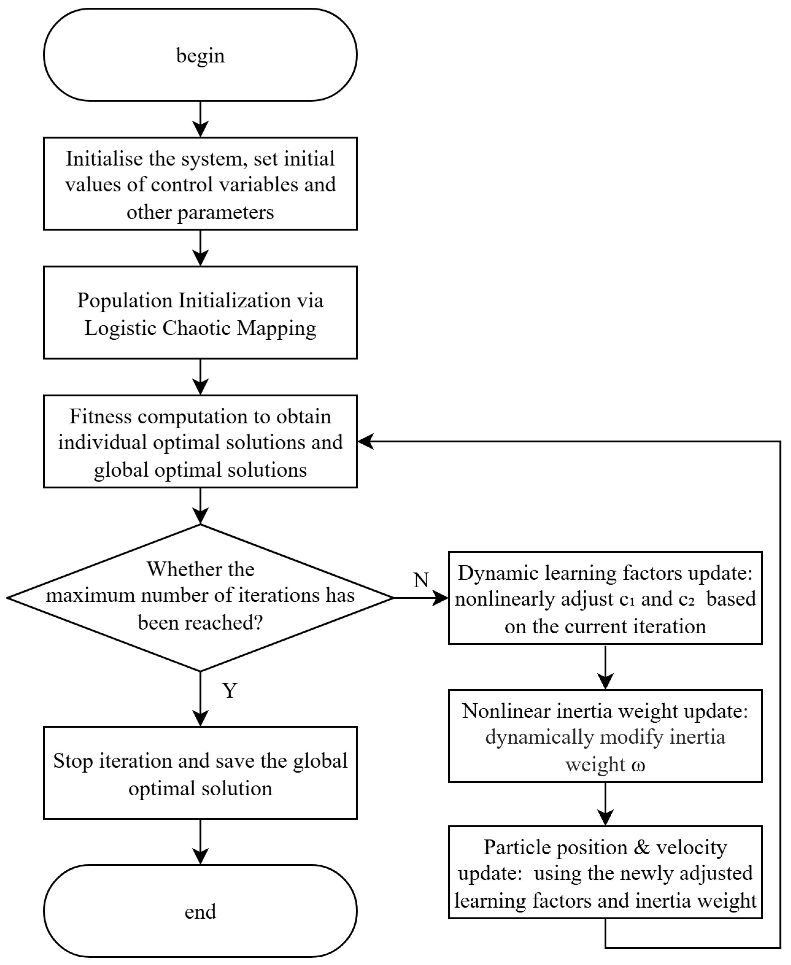
The standard PSO algorithm, constrained by its fixed-parameter mechanism, exhibits three fundamental limitations: progressive convergence degradation, acute parameter dependence, and premature convergence tendencies, which collectively impair its path planning performance in complex scenarios. In order to solve the above problems, this paper introduces logistic chaotic mapping, the dynamic learning factor and nonlinear inertia weights to avoid the particle swarm algorithm falling into the local optimal solution and the defects of too fast convergence speed. The following is the improvement of the particle swarm algorithm. The workflow of IPSO algorithm is shown in
Figure 4.
4.2. Population Initialization via Logistic Chaotic Mapping
Conventional PSO initializes particle positions randomly, often inducing clustered distributions in local regions that increase susceptibility to local optima trapping, reduce convergence speed, and constrain global exploration capacity. To address these limitations, we employ logistic chaotic mapping for population initialization. By enhancing particle diversity and stochasticity, this approach significantly improves adaptability in edge intelligence environments through real-time generation of diversified solution distributions. This capability enables a dynamic response to environmental perturbations and effective adaptation to moving obstacles, while edge computing scenarios such as UAV path planning, empowers edge nodes to rapidly generate globally dispersed initial trajectories that intrinsically prevent premature convergence.
The logistic chaotic system is mathematically defined by Equation (15):
where
denotes the chaotic variable at iteration
, and
in (3.57, 4] represents the bifurcation parameter. When
, the system exhibits maximal chaotic behavior. Following prior studies [
57,
58,
59], values of
within this range are widely adopted to enhance chaotic dynamics and increase population diversity in path planning algorithms. In this study, we set
, which maintains sufficient chaotic characteristics while improving numerical stability during initialization.
4.3. Dynamic Learning Factor Scheme
To enhance global convergence capabilities, we refined the learning factor adaptation mechanism. In conventional PSO, learning factors and typically remain static constants. Oversized values lead to excessive local exploitation through over-reliance on individual experience, while elevated values trigger premature convergence to local optima. Addressing these limitations, we propose a dynamic learning factor scheme that adaptively modulates and values according to iterative progression phases.
During the initial iteration phases of the algorithm, it is essential to strengthen particles’ cognitive learning capabilities to facilitate extensive exploration of the search space. Conversely, in later iteration stages, enhancing particles’ social learning abilities becomes critical to preventing algorithmic entrapment in local optima and to drive asymptotic convergence toward the global optimum. Therefore, we adopt an elevated value and a reduced value during early iterations. This configuration amplifies cognitive learning while diminishing social influence, thereby augmenting population diversity. During later iterations, a diminished value and an elevated value are employed to intensify social learning, promoting convergence toward the globally optimal solution.
Prior research has implemented linear modifications to the learning factors [
60], where
decreases monotonically and
increases monotonically with progressive iterations. These refined linear learning factors are expressed in Equations (16) and (17):
where
,
,
,
, respectively, represent the starting and final values of
and the starting and final values of
,
represents the current iteration number, and
represents the maximum iteration number.
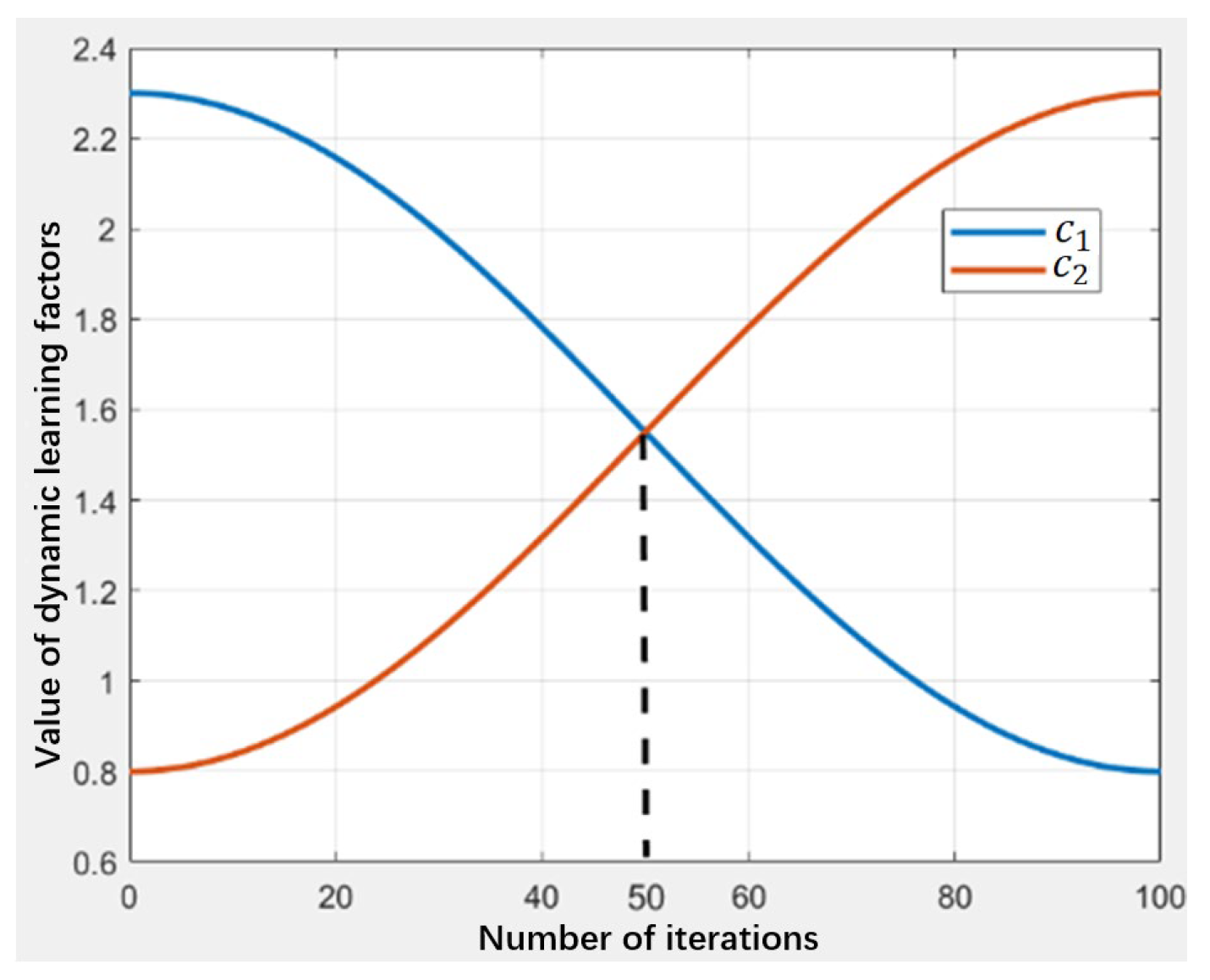
Although linearly modified learning factors achieve accelerated convergence rates, they remain prone to premature convergence to local optima in path planning scenarios. To address this limitation, this paper introduces a nonlinear refinement of the learning factors. The enhanced formulation intensifies global exploration capabilities during initial search phases while amplifying local exploitation efficacy in later stages. These modified learning factors are defined in Equations (18) and (19):
where
denotes the current iteration count and
represents the maximum iteration count. Let
. The equality
holds if and only if
, which yields
. For this study,
, resulting in
at
. The functional profiles of the refined learning factors are illustrated in
Figure 5.
As evidenced in
Figure 5, the inequality
holds for
whereas
is maintained for
. Consequently, the refined learning factors achieve the intended behavioral adaptation: elevated
with suppressed
during initial iterations for enhanced exploration, transitioning to diminished
with amplified
in later stages to intensify exploitation.
The incorporation of dynamic learning factors enables the algorithm to adaptively modulate its search strategy according to iterative phases, demonstrating particular efficacy for complex task allocation in edge intelligence environments. Within edge-cloud collaborative computing frameworks, these adaptive factors optimally balance global exploration and local exploitation, thereby enhancing both computational efficiency and solution accuracy in path planning.
4.4. Nonlinear Inertia Weight Mechanism
The performance of standard PSO exhibits significant dependence on the configuration of the inertia weight parameter. During initial algorithm iterations, enhancing particles’ global optimization capabilities necessitates assigning a larger inertia weight, enabling rapid exploration of the entire search space. Conversely, in later iterations, strengthening local optimization proficiency requires a reduced inertia weight to prevent premature convergence to local optima. Consequently, a progressively decaying inertia weight strategy effectively mitigates particle entrapment in suboptimal solutions. Prior research has adopted a linear decay strategy for the inertia weight [
61], formulated in Equation (20):
where
and
denote the minimum and maximum inertia weights, respectively,
represents the current iteration count, and
signifies the maximum iteration count.
However, the linear decay inertia weight strategy exhibits critical deficiencies, including premature convergence, suboptimal convergence rates, and limited environmental adaptability. To overcome these limitations, this paper proposes a nonlinear inertia weight strategy. During real-time data processing on edge nodes, this mechanism dynamically adjusts particles’ search velocity according to iterative phases, preventing premature convergence while simultaneously enhancing algorithmic stability and convergence speed. The formulation is presented in Equation (21):
In this work,
= 0.9 and
= 0.4, consistent with widely adopted parameter settings in swarm intelligence research [
62,
63]. These values provide a practical balance: a larger initial inertia weight encourages global exploration, while a smaller final inertia weight strengthens local exploitation and stabilizes convergence.
denotes the current iteration count, and
is a positive constant that controls the nonlinearity of the inertia weight decay, set to 40 in this study based on preliminary tuning, which we found to be sufficient in preventing premature convergence without compromising computational efficiency. The refined velocity update formulation is given in Equation (22):
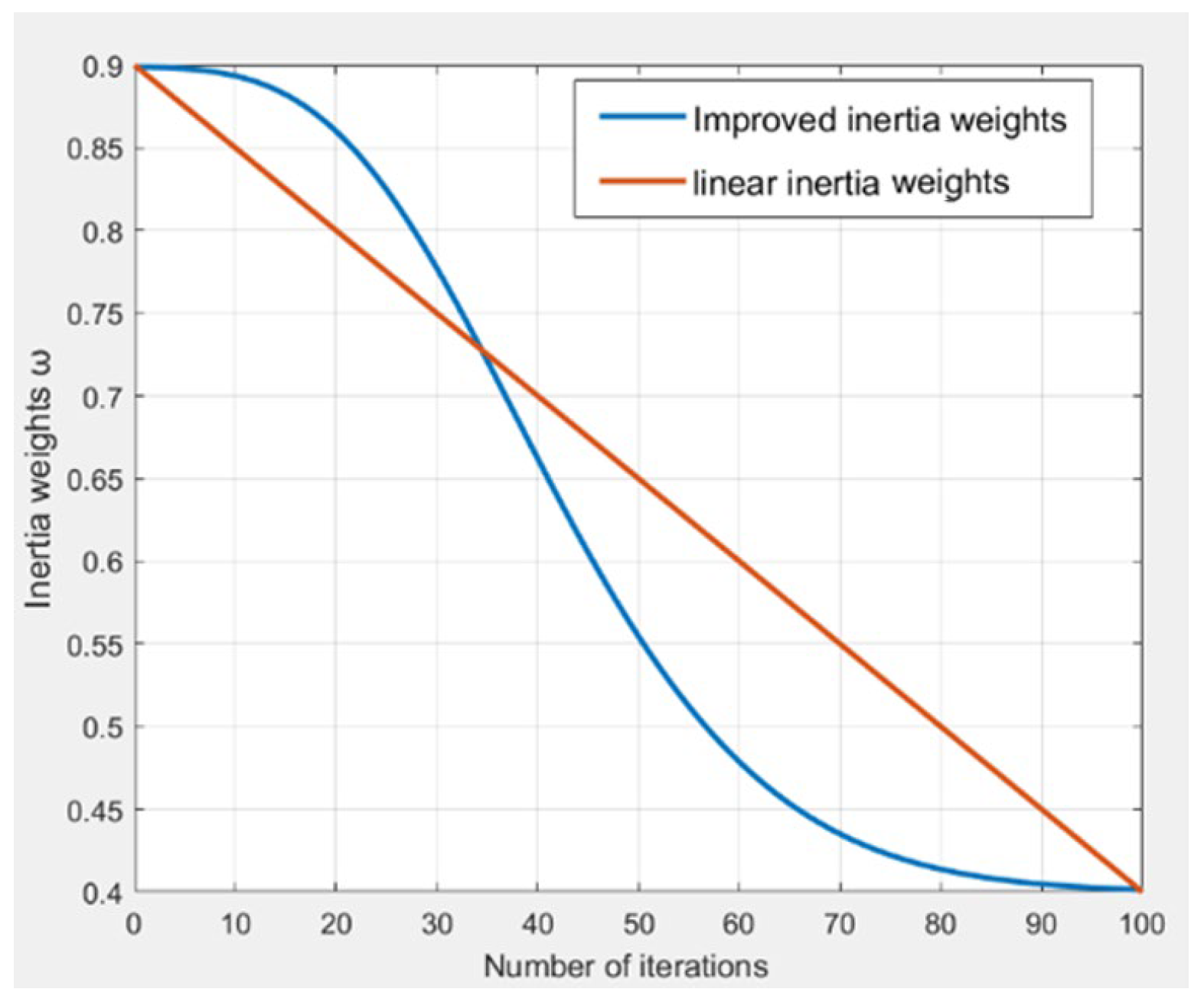
The comparative profiles of the improved nonlinear inertia weight versus its linear counterpart are illustrated in
Figure 6.
As evidenced in
Figure 6, the refined nonlinear inertia weight exhibits higher magnitudes than its linear counterpart during initial iterations, thereby intensifying particles’ global exploration capabilities. Conversely, in later stages, it maintains lower values than the linear variant, enhancing local exploitation efficacy. Consequently, this adaptive formulation better aligns with the iterative requirements of Particle Swarm Optimization.
The design of this nonlinear inertia weight enables superior adaptation to dynamic computational resources in edge intelligence environments. During real-time data processing on edge nodes, it significantly accelerates convergence rates and improves algorithmic stability, delivering robust support for path planning in complex scenarios.
5. Experimental Simulations and Results Analysis
5.1. Experimental Setup
To validate the efficacy of the Improved Particle Swarm Optimization (IPSO) in path planning, comparative experiments were conducted against six benchmark algorithms: Particle Swarm Optimization (PSO), Ant Colony Optimization (ACO), Artificial Fish Swarm Algorithm (AFSA) [
64], Grey Wolf Optimizer (GWO) [
65], Artificial Bee Colony (ABC) [
66], and Genetic Algorithm (GA) [
67]. To ensure fairness, all algorithms utilized the B-spline parameterization method from
Section 3.2 with five control points and a smoothing factor
. Simulations employed three distinct terrain maps, with key parameters configured as shown in
Table 2.
5.2. Results Analysis
5.2.1. Path Planning Distance Comparison
Firstly, path planning experiments were executed on Map 1. To evaluate optimal path identification capabilities, 100 Monte Carlo trials per algorithm were performed, with path lengths recorded at iterative milestones (
). Results are quantified in
Table 3.
As quantified in
Table 3, IPSO generates the shortest planned path at only 152.0671 m, while the Genetic Algorithm (GA) exhibits the poorest performance with a path length of 229.1915 m. Significant divergence exists in the iterations required for algorithms to converge to their respective optimal solutions.
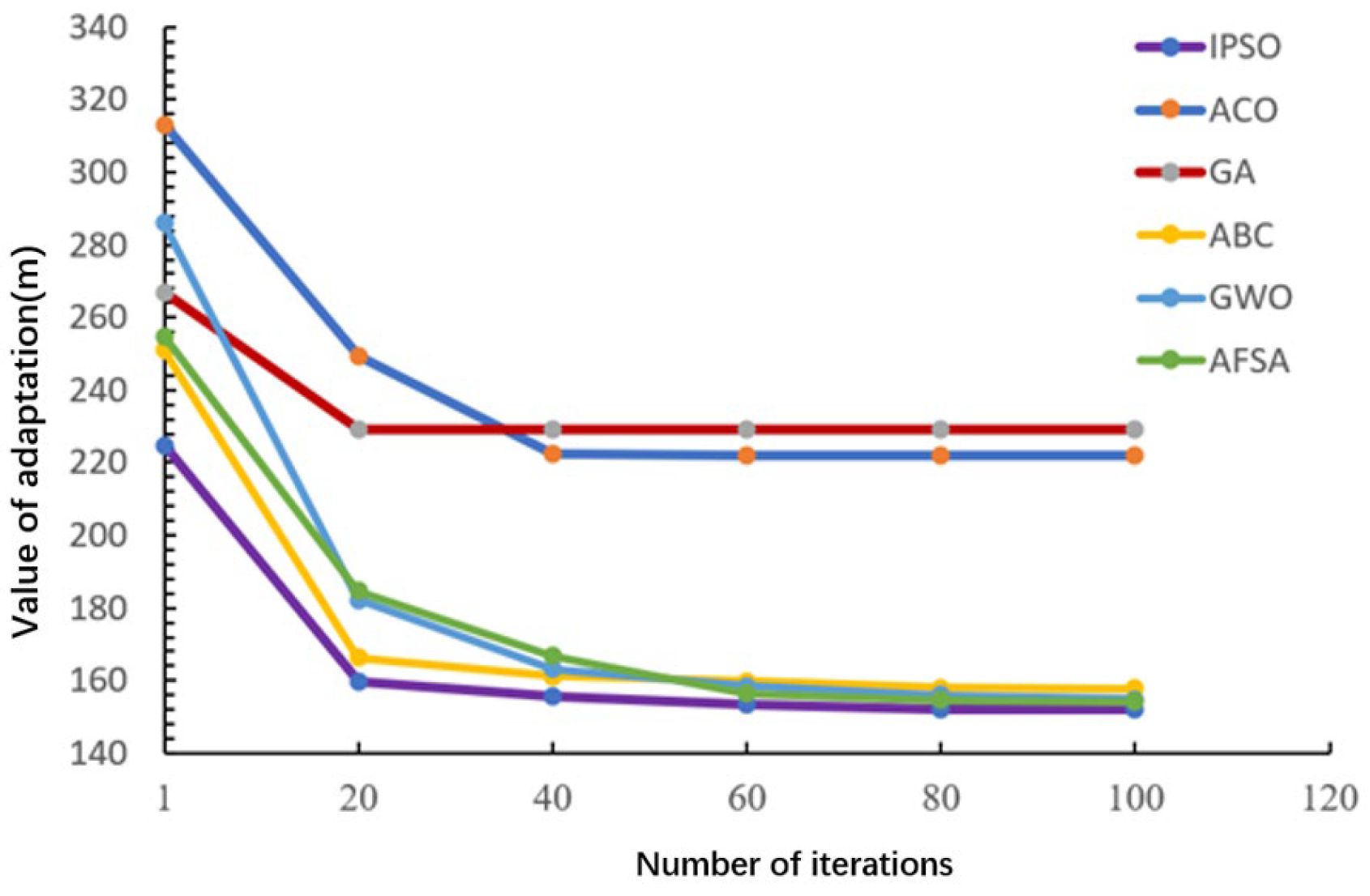
Given the experimental configuration with start point (1, 1, 1) and goal (100, 100, 20), the theoretical global optimum path length is calculated as 141.2905 m. Algorithmic efficacy is evaluated by proximity to this theoretical minimum. As empirically demonstrated in
Figure 7, IPSO achieves its algorithmic optimum within 20 iterations, whereas other methods—particularly GA and ACO—yield solutions significantly farther from the theoretical optimum.
5.2.2. Computational Time Analysis
Computational time represents a critical performance metric for path planning algorithms. We conducted 100 experimental trials on Map 1 and recorded the execution time at iterative milestones (
). Quantitative results are presented in
Table 4.
As quantified in
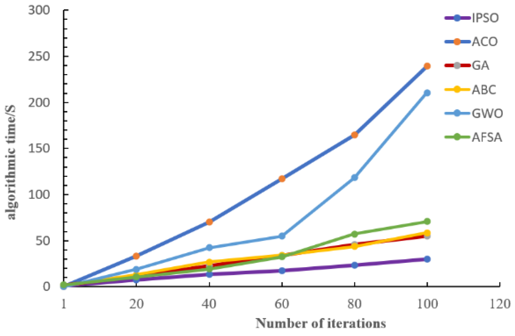
Table 4, IPSO exhibits significantly lower computational overhead, while Ant Colony Optimization (ACO) and Grey Wolf Optimizer (GWO) demonstrate prohibitive time consumption—approximately eight times longer than IPSO at final iteration. This substantial disparity stems from the inherently higher computational complexity and iteration constraints of ACO and GWO. The comparative time costs across algorithms at 100 iterations are empirically validated in
Figure 8.
As empirically validated in
Figure 8, IPSO exhibits a flat computational-time progression with significantly reduced total execution time compared to alternative algorithms. This efficiency advantage fundamentally originates from IPSO’s robust avoidance of local optima entrapment, which prevents redundant recomputation cycles.
5.2.3. Comparison of Path Planning Outcomes
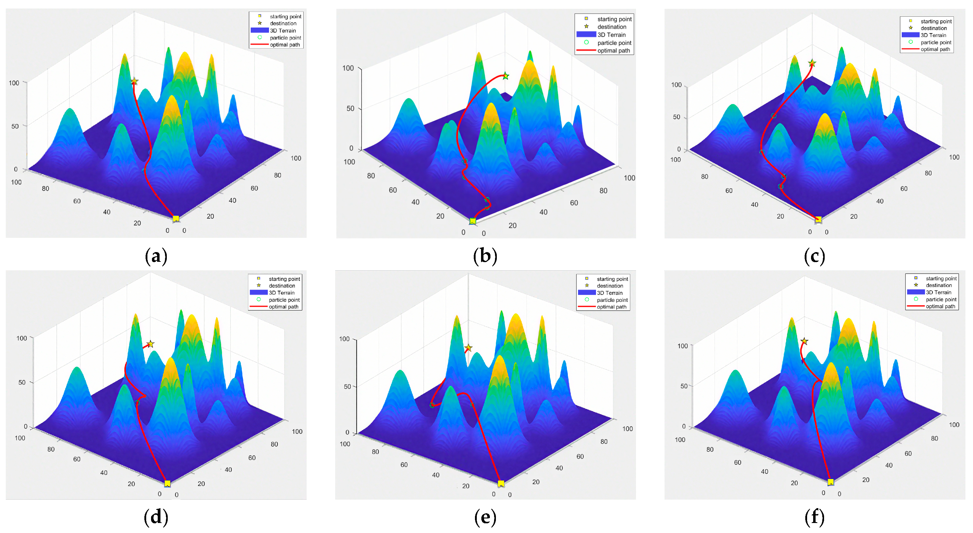
For intuitive evaluation of algorithmic path planning efficacy, the optimal path generated by each algorithm are comparatively visualized in
Figure 9.
As shown in
Figure 9, the B-spline path planned by IPSO is smoother and shorter, making it particularly suitable for complex task allocation in edge intelligence environments. In practical applications, this path planning effect can significantly enhance the system’s real-time performance and robustness. In contrast, paths planned by other algorithms (such as Ant Colony Optimization and Genetic Algorithm) exhibit significant inflection points. While the Wolf Pack Algorithm does not produce nodes with high curvature, the planned path distance is longer, resulting in greater implementation complexity.
5.2.4. Multi-Map Performance Validation
To validate algorithm adaptability across diverse environments, experiments were conducted on Maps 2 and 3. Combined with Map 1 results, we calculated six metrics per algorithm:
Experimental results are presented in
Table 5.
As shown in
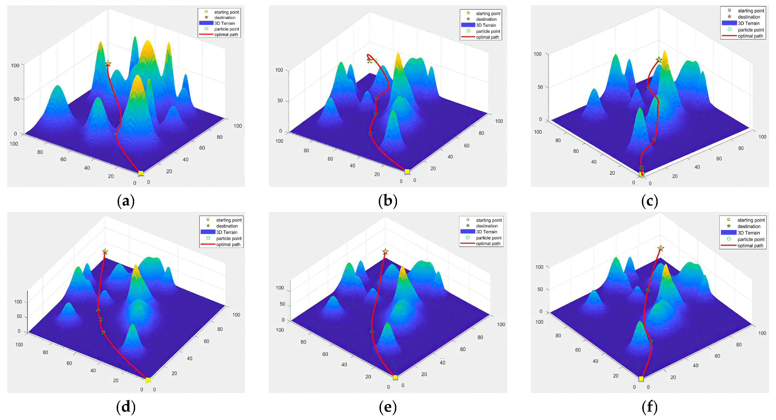
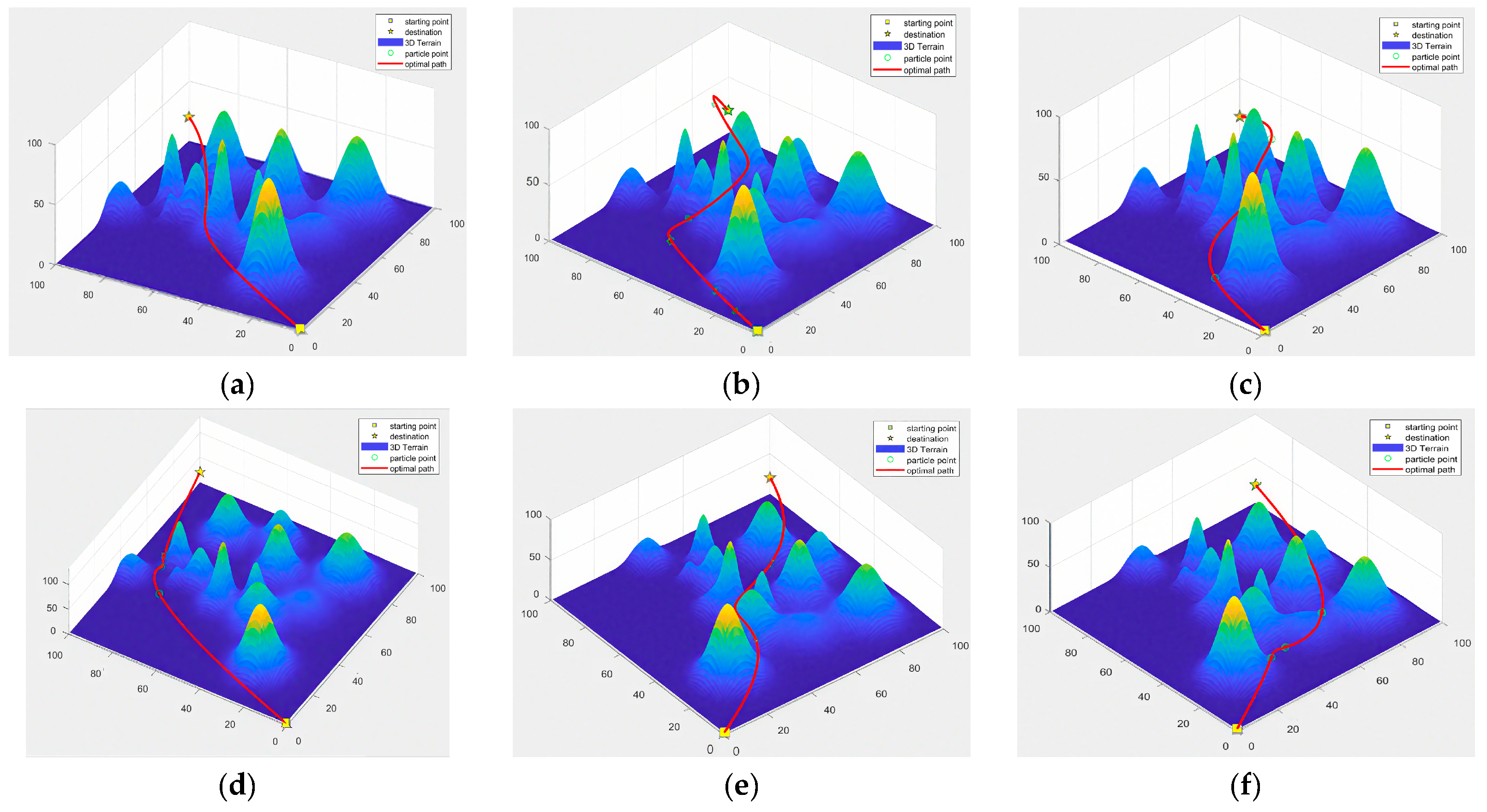
Table 5, IPSO outperforms other algorithms across all performance metrics on different terrain environments. It achieves optimal path length while exhibiting lower dispersion in path length distribution and a more minor standard deviation, indicating enhanced stability and robust adaptability for edge intelligence environments. The path planning results of all algorithms on Map 2 and Map 3 are illustrated in
Figure 10 and
Figure 11, respectively.
As visually apparent in
Figure 10 and
Figure 11, the IPSO algorithm generates significantly smoother and shorter paths while demonstrating superior map adaptability. Conversely, paths planned by other algorithms exhibit pronounced inflection points, resulting in substantially higher implementation complexity.
6. Conclusions and Future Work
Traditional Particle Swarm Optimization (PSO) updates particle velocity through a weighted summation of global and individual optimal solutions. Yet, its fixed learning factors and inertia weights frequently precipitate premature convergence to local optima, accompanied by excessively rapid convergence rates. To mitigate these limitations, this paper proposes an enhanced PSO algorithm (IPSO) incorporating dynamically adjusted learning factors and nonlinear inertia weights, substantially augmenting algorithmic flexibility and adaptability. The dynamic learning factors modulate the relative influence of global versus individual optima across iterative phases, facilitating extensive search space exploration during initial iterations while accelerating convergence toward the global optimum in later stages. Concurrently, nonlinear inertia weights dynamically regulate particle search velocity to prevent premature convergence while enhancing stability and convergence efficiency. Additionally, logistic chaotic mapping is employed for particle population initialization, significantly enhancing randomness and diversity. Through judicious parameter selection and adjustment, the refined algorithm demonstrates superior adaptability to heterogeneous terrains and achieves marked improvements in path planning efficacy. Experimental validation confirms the enhanced PSO’s consistent outperformance of conventional algorithms across critical metrics: path length reduction (average 14.4% shorter paths) and computational efficiency (65.04% faster processing), while exhibiting strengthened adaptability and robustness.
Looking ahead, while IPSO excels in simulation-based path planning, its practical deployment requires further validation on real UAV and robotic platforms, particularly under noisy sensor data, communication latency, and dynamic obstacle environments. Such real-world testing will be crucial for bridging the gap between controlled experiments and operational scenarios. Moreover, extending the current geometric optimization framework to incorporate UAV dynamics, turning radius constraints, and energy consumption models will be essential to ensure that planned trajectories are not only smooth and collision-free but also physically realizable and energy-efficient.
Another important avenue is to broaden the benchmarking of IPSO by including state-of-the-art Deep Reinforcement Learning (DRL) and hybrid heuristic learning approaches, which represent emerging paradigms in autonomous navigation. In parallel, the integration of IPSO with edge intelligence and industrial IoT infrastructures offers promising opportunities for real-time path planning in complex and resource-constrained environments.
Furthermore, future research will explore multi-agent UAV coordination and energy-aware path planning as logical extensions of IPSO. Additionally, integrating onboard sensing feedback for dynamic re-planning in uncertain environments will improve the algorithm’s robustness in real-world applications.
Finally, deeper analyses of the algorithm’s convergence mechanisms, as well as synergistic combinations with complementary optimization strategies, may further enhance its global search ability and adaptability across domains.
Author Contributions
Conceptualization, J.M.; methodology, J.M. and Z.Y.; validation, J.M. and M.C.; data curation, Z.Y.; writing—original draft preparation, Z.Y.; writing—review and editing, J.M. and Z.Y.; supervision, J.M. and M.C.; funding acquisition, M.C. All authors have read and agreed to the published version of the manuscript.
Funding
This research was funded by Tongling University Talent Research Start-up Fund Project, grant number 2024tlxyrc019 and funded by Anhui Provincial KeyResearch and Development Project, grant number 2024AH053415.
Data Availability Statement
Research data are readily provided upon request.
Conflicts of Interest
Author Zixu Yang was employed by the company “Anhui Houpu Digital Technology Co., Ltd.”. The remaining authors declare that the research was conducted in the absence of any commercial or financial relationships that could be construed as a potential conflict of interest.
References
- Urrea, C.; Kern, J. Recent Advances and Challenges in Industrial Robotics: A Systematic Review of Technological Trends and Emerging Applications. Processes 2025, 13, 832. [Google Scholar] [CrossRef]
- Zhang, J.; Zhu, X.; Chen, T.; Dou, G. Optimal Dynamics Control in Trajectory Tracking of Industrial Robots Based on Adaptive Gaussian Pseudo-Spectral Algorithm. Algorithms 2025, 18, 18. [Google Scholar] [CrossRef]
- Jiang, X.; Li, X.; Sun, Y.; Zhu, H. Kinematic Calibration of Industrial Robots Based on Binocular Vision Distance Error Measurement. Jiliang Xuebao/Acta Metrol. Sin. 2024, 45, 1470–1479. [Google Scholar] [CrossRef]
- Igwenagu, U.T.I.; Debnath, R.; Ahmed, A.A.; Alam, M.J.B. An Integrated Approach for Earth Infrastructure Monitoring Using UAV and ERI: A Systematic Review. Drones 2025, 9, 225. [Google Scholar] [CrossRef]
- Jin, I.J.; Lim, D.Y.; Bang, I.C. Development of fault diagnosis for nuclear power plant using deep learning and infrared sensor equipped UAV. Ann. Nucl. Energy 2023, 181, 109577. [Google Scholar] [CrossRef]
- Karegar, P.A.; Al-Hamid, D.Z.; Chong, P.H.J. Deep Reinforcement Learning for UAV-Based SDWSN Data Collection. Future Internet 2024, 16, 398. [Google Scholar] [CrossRef]
- Jiang, C.; Yang, L.; Gao, Y.; Zhao, J.; Hou, W.; Xu, F. An Intelligent 5G Unmanned Aerial Vehicle Path Optimization Algorithm for Offshore Wind Farm Inspection. Drones 2025, 9, 47. [Google Scholar] [CrossRef]
- Li, Y.; Liu, L. Research on AGV Path Planning Based on Improved Directed Weighted Graph Theory and ROS Fusion. Actuators 2024, 13, 404. [Google Scholar] [CrossRef]
- Vaccari, L.; Coruzzolo, A.M.; Lolli, F.; Sellitto, M.A. Indoor Positioning Systems in Logistics: A Review. Logistics 2024, 8, 126. [Google Scholar] [CrossRef]
- Li, T.; Wang, Z. Multi objective optimization scheduling of unmanned warehouse handling robots based on A star algorithm. Concurr. Comput. Pract. Exp. 2024, 36, e8064. [Google Scholar] [CrossRef]
- Han, L.; Ding, J.; Liu, S.; Meng, M. The Path Planning Problem of Robotic Delivery in Multi-Floor Hotel Environments. Sensors 2025, 25, 1783. [Google Scholar] [CrossRef] [PubMed]
- Gonçalves, A.; Pereira, T.; Lopes, D.; Cunha, F.; Lopes, F.; Coutinho, F.; Barreiros, J.; Durães, J.; Santos, P.; Simões, F.; et al. Enhancing Nut-Tightening Processes in the Automotive Industry: Integration of 3D Vision Systems with Collaborative Robots. Automation 2025, 6, 8. [Google Scholar] [CrossRef]
- Zhang, Q.; Li, H.; Duan, J.; Qin, J.; Zhou, Y. Multi-Objective Point Motion Planning for Assembly Robotic Arm Based on IPQ-RRT* Connect Algorithm. Actuators 2023, 12, 459. [Google Scholar] [CrossRef]
- Zhang, Y.; Li, Y.; Feng, Q.; Sun, J.; Peng, C.; Gao, L.; Chen, L. Compliant Motion Planning Integrating Human Skill for Robotic Arm Collecting Tomato Bunch Based on Improved DDPG. Plants 2025, 14, 634. [Google Scholar] [CrossRef]
- Merei, A.; Mcheick, H.; Ghaddar, A.; Rebaine, D. A Survey on Obstacle Detection and Avoidance Methods for UAVs. Drones 2025, 9, 203. [Google Scholar] [CrossRef]
- Choi, Y.; Kim, H. Obstacle-Aware Crowd Surveillance with Mobile Robots in Transportation Stations. Sensors 2025, 25, 350. [Google Scholar] [CrossRef]
- Mohammed, H.; Ibrahim, M.; Raoof, A.; Jaleel, A.; Al-Dujaili, A.Q. Modified Ant Colony Optimization to Improve Energy Consumption of Cruiser Boundary Tour with Internet of Underwater Things. Computers 2025, 14, 74. [Google Scholar] [CrossRef]
- Wang, L.; Yu, S.; Li, M.; Wei, X. Multi-Task Agent Hybrid Control in Sparse Maps and Complex Environmental Conditions. Appl. Sci. 2024, 14, 10377. [Google Scholar] [CrossRef]
- Zhang, H.; Yang, T.; Su, Z. A formation cooperative reconnaissance strategy for multi-UGVs in partially unknown environment. J. Chin. Inst. Eng. 2023, 46, 551–562. [Google Scholar] [CrossRef]
- González-Morgado, A.; Ollero, A.; Heredia, G. Control Barrier Functions in Multirotors: A Safety Filter for Obstacle Avoidance; Lecture Notes in Networks and Systems (LNNS); Springer: Cham, Switzerland, 2024; Volume 978, pp. 14–25. [Google Scholar] [CrossRef]
- Jayaweera, H.M.P.C.; Hanoun, S. UAV Path Planning for Reconnaissance and Look-Ahead Coverage Support for Mobile Ground Vehicles. Sensors 2021, 21, 4595. [Google Scholar] [CrossRef]
- Adam, M.S.; Abdullah, N.F.; Abu-Samah, A.; Amodu, O.A.; Nordin, R. Advanced Path Planning for UAV Swarms in Smart City Disaster Scenarios Using Hybrid Metaheuristic Algorithms. Drones 2025, 9, 64. [Google Scholar] [CrossRef]
- Yuan, D.; Zhong, Y.; Zhu, X.; Chen, Y.; Jin, Y.; Du, X.; Tang, K.; Huang, T. Trajectory Planning for Unmanned Vehicles on Airport Apron Under Aircraft–Vehicle–Airfield Collaboration. Sensors 2025, 25, 71. [Google Scholar] [CrossRef]
- García-Munguía, A.; Guerra-Ávila, P.L.; Islas-Ojeda, E.; Flores-Sánchez, J.L.; Vázquez-Martínez, O.; García-Munguía, A.M.; García-Munguía, O. A Review of Drone Technology and Operation Processes in Agricultural Crop Spraying. Drones 2024, 8, 674. [Google Scholar] [CrossRef]
- Wang, Z.; Li, G. Research on Path Planning Algorithm of Driverless Ferry Vehicles Combining Improved A* and DWA. Sensors 2024, 24, 4041. [Google Scholar] [CrossRef]
- Suanpang, P.; Jamjuntr, P. Optimizing Autonomous UAV Navigation with D* Algorithm for Sustainable Development. Sustainability 2024, 16, 7867. [Google Scholar] [CrossRef]
- Meng, X.; Fang, X. A UGV Path Planning Algorithm Based on Improved A* with Improved Artificial Potential Field. Electronics 2024, 13, 972. [Google Scholar] [CrossRef]
- Noroozi, F.; Daneshmand, M.; Fiorini, P. Conventional, Heuristic and Learning-Based Robot Motion Planning: Reviewing Frameworks of Current Practical Significance. Machines 2023, 11, 722. [Google Scholar] [CrossRef]
- Qin, H.; Shao, S.; Wang, T.; Yu, X.; Jiang, Y.; Cao, Z. Review of Autonomous Path Planning Algorithms for Mobile Robots. Drones 2023, 7, 211. [Google Scholar] [CrossRef]
- Tang, Y.; Zakaria, M.A.; Younas, M. Path Planning Trends for Autonomous Mobile Robot Navigation: A Review. Sensors 2025, 25, 1206. [Google Scholar] [CrossRef]
- Fu, S.; Yang, D.; Mei, Z.; Zheng, W. Progress in Construction Robot Path-Planning Algorithms: Review. Appl. Sci. 2025, 15, 1165. [Google Scholar] [CrossRef]
- Karpenko, M.; Stosiak, M.; Deptuła, A.; Urbanowicz, K.; Nugaras, J.; Królczyk, G.; Żak, K. Performance evaluation of extruded polystyrene foam for aerospace engineering applications using frequency analyses. Int. J. Adv. Manuf. Technol. 2023, 126, 5515–5526. [Google Scholar] [CrossRef]
- Karpenko, M.; Nugaras, J. Vibration damping characteristics of the cork-based composite material in line to frequency analysis. J. Theor. Appl. Mech. 2022, 60, 593–602. [Google Scholar] [CrossRef]
- Zheng, Y.; Li, Y.; Cheng, J.; Li, C.; Hu, S. Two-Stage Hierarchical 4D Low-Risk Trajectory Planning for Urban Air Logistics. Drones 2025, 9, 267. [Google Scholar] [CrossRef]
- Ji, Y.; Liu, Q.; Zhou, C.; Han, Z.; Wu, W. Hybrid Swarm Intelligence and Human-Inspired Optimization for Urban Drone Path Planning. Biomimetics 2025, 10, 180. [Google Scholar] [CrossRef]
- Zhou, X.; Shi, G.; Zhang, J. Improved Grey Wolf Algorithm: A Method for UAV Path Planning. Drones 2024, 8, 675. [Google Scholar] [CrossRef]
- Liu, G.C.; Ma, Y.S.; Qi, F.Q.; Xu, Y. Flight path planning for urban logistics UAV based on improved A*-APF algorithm. Flight Dyn. 2022, 40, 16–23. [Google Scholar]
- Zhan, J.W.; Huang, Y.Q. Path Planning of Robot Combing Safety A* Algorithm and Dynamic Window Approach. Comput. Eng. 2022, 48, 105–112+120. [Google Scholar]
- Cai, M.; Xue, J.; Gao, H.W.; Li, H.Y.; Tao, Z.B. Flexible Needle Rrt Path Planning Algorithm Based On Cost Function Optimization. Comput. Appl. Softw. 2022, 39, 245–249+296. [Google Scholar]
- Chen, F.F.; Jiang, H.; Li, Z.; Xiao, W.; Chen, B. Narrow Channel Path Planning of Intelligent Inspection Robot Based on Improved RRT. Modul. Mach. Tool Autom. Manuf. Tech. 2022, 10, 40–45. [Google Scholar]
- Chen, Q.L.; Zheng, Y.J.; Jiang, H.Y. Dynamic path planning based on neural network improved particle swarm algorithm. J. Huazhong Univ. Sci. Technol. (Nat. Sci. Ed.) 2021, 49, 51–55. [Google Scholar]
- Mobarez, E.N.; Sarhan, A.; Ashry, M.M. Obstacle avoidance for multi-UAV path planning based on particle swarm optimization. IOP Conf. Ser. Mater. Sci. Eng. 2021, 1172, 012039. [Google Scholar] [CrossRef]
- Yang, X.; Wei, P.; Zhang, Y.; Liu, X.; Yang, L. Disturbance observer based on biologically inspired integral sliding Mode control for trajectory tracking of mobile robots. IEEE Access 2019, 7, 48382–48391. [Google Scholar] [CrossRef]
- Li, J.; Gao, J.C. Robot path planning based on improved ant colony algorithm. Autom. Instrum. 2020, 35, 39–43. [Google Scholar]
- Fu, Y.; Yang, S.; Liu, B.; Xia, E.; Huang, D. Multi-UAV Cooperative Trajectory Planning Based on the Modified Cheetah Optimization Algorithm. Entropy 2023, 25, 1277. [Google Scholar] [CrossRef]
- Wang, S.Y.; Zhang, L.W.; Qi, J.L.; Gai, Y.C. Adaptive guided ant colony algorithm to optimize the path planning of mobile robots. Appl. Res. Comput. 2020, 37, 116–117+119. [Google Scholar]
- Ma, J.; Liu, Q.; Yang, Z.; Wang, B. Improved Trimming Ant Colony Optimization Algorithm for Mobile Robot Path Planning. Algorithms 2025, 18, 240. [Google Scholar] [CrossRef]
- Ma, M.X.; Wu, J.; Yue, L.F.; Yan, M.D.; Yu, J.Y. Autonomous flight path planning for UAVs based on improved artificial fish swarm optimization with ant colony algorithm. J. Arms Equip. Eng. 2022, 43, 257–265. [Google Scholar]
- Fan, J.; Lei, T.; Dong, N.J.; Wang, R. Multi-target UAV path planning based on improved NSGA-II algorithm. Firepower Command Control 2022, 47, 43–48+55. [Google Scholar]
- Sun, J.; Tang, J.; Lao, S. Collision avoidance for cooperative UAVs with optimized artificial potential field algorithm. IEEE Access 2017, 5, 18382–18390. [Google Scholar] [CrossRef]
- Fu, X.W.; Hu, Y. Three-dimensional path planning based on improved particle swarm algorithm. Electro-Opt. Control 2021, 28, 86–89. [Google Scholar]
- Gupta, H.; Verma, O.P. A novel hybrid Coyote–Particle Swarm Optimization Algorithm for three-dimensional constrained trajectory planning of Unmanned Aerial Vehicle. Appl. Soft Comput. 2023, 147, 110776. [Google Scholar] [CrossRef]
- Meng, Q.; Chen, K.; Qu, Q. PPSwarm: Multi-UAV Path Planning Based on Hybrid PSO in Complex Scenarios. Drones 2024, 8, 192. [Google Scholar] [CrossRef]
- Rosas-Carrillo, A.S.; Solís-Santomé, A.; Silva-Sánchez, C.; Camacho-Nieto, O. UAV Path Planning Using an Adaptive Strategy for the Particle Swarm Optimization Algorithm. Drones 2025, 9, 170. [Google Scholar] [CrossRef]
- Qi, Z.; Shao, Z.; Ping, Y.S.; Hiot, L.M.; Leong, Y.K. An improved heuristic algorithm for uav path planning in 3d environment. In Proceedings of the 2010 Second International Conference on Intelligent Human-Machine Systems and Cybernetics, Nanjing, China, 26–28 August 2010; IEEE: Piscataway, NJ, USA, 2010. [Google Scholar] [CrossRef]
- Huang, S.Z.; Tian, J.W.; Qiao, L.; Wang, Q.; Su, Y. Unmanned aerial vehicle path planning based on improved genetic algorithm. J. Comput. Appl. 2021, 41, 390–397. [Google Scholar]
- Zheng, X.; Diao, C.; Cai, G.; Li, Y. Research on Mine Rescue UAV Path Planning Based on an Improved Artificial Jellyfish Search Algorithm. Ind. Mine Autom. 2025, 51, 61–70. [Google Scholar] [CrossRef]
- Ma, X.; Yuan, S.; Wang, B.; Zhang, H. Research on RRT* Path Planning Algorithm Based on Uniformly Distributed Logistic Chaotic Sequence. Mech. Sci. Technol. Aerosp. Eng. 2022, 41, 610–618. [Google Scholar] [CrossRef]
- Yang, C.; Pei, Y.; Liu, P. Research on 3D Path Planning Based on an Improved Particle Swarm Optimization Algorithm. Comput. Eng. Appl. 2019, 55, 117–122. [Google Scholar]
- Qu, L.G.; Jiang, S.; Yang, Y.G.; Li, J. Research on cable path planning method based on improved PSO algorithm. Mach. Tool Hydraul. 2023, 51, 173–177. [Google Scholar]
- Liu, P.D. Some geometric aggregation operators based on interval intuitionistic uncertain linguistic variables and their application to group decision making. Appl. Math. Model. 2013, 37, 2430–2444. [Google Scholar] [CrossRef]
- Zhang, X.; Zheng, S.; Zheng, X.; Wu, Y. Particle Swarm Optimization Algorithm with Nonlinear Inertia Weight and t-Distribution Disturbance. J. Hangzhou Dianzi Univ. (Nat. Sci.) 2025, 45, 13–19+27. [Google Scholar] [CrossRef]
- Wu, G.; Wan, L. Research on Robot Path Planning Optimization Based on Particle Swarm Optimization Algorithm. Mech. Sci. Technol. Aerosp. Eng. 2022, 41, 1759–1764. [Google Scholar] [CrossRef]
- Zhang, T.; Li, S.B.; Zhang, A.S.; Zheng, C.J.; Wu, F.B. 3D path planning for unmanned aerial vehicle in complex landscape based on improved artificial fish swarm algorithm. Sci. Technol. Eng. 2023, 23, 4433–4439. [Google Scholar]
- Roberge, V.; Tarbouchi, M.; Labonte, G. Comparison of parallel genetic algorithm and particle swarm optimization for real-time UAV path planning. IEEE Trans. Ind. Inform. 2013, 9, 132–141. [Google Scholar] [CrossRef]
- Zhu, J.L.; Yuan, X.B.; Pei, J. Path planning in disaster scenarios based on improved artificial bee colony algorithm. J. Univ. Chin. Acad. Sci. 2023, 40, 397–405. [Google Scholar] [CrossRef]
- Babaie, O.; Nasr Esfahany, M. Optimization and heat integration of hybrid R-HIDiC and pervaporation by combining GA and PSO algorithm in TAME synthesis. Sep. Purif. Technol. 2020, 236, 116288. [Google Scholar] [CrossRef]
Figure 1.
Three-Dimensional Terrain Model. Color represents elevation, with blue indicating lower altitudes and yellow indicating higher altitudes.
Figure 1.
Three-Dimensional Terrain Model. Color represents elevation, with blue indicating lower altitudes and yellow indicating higher altitudes.
Figure 2.
Curvature and torsion.
Figure 2.
Curvature and torsion.
Figure 3.
Performance of B-spline path fitting. The green squares represent the key waypoints.
Figure 3.
Performance of B-spline path fitting. The green squares represent the key waypoints.
Figure 4.
Flowchart of the IPSO Algorithm.
Figure 4.
Flowchart of the IPSO Algorithm.
Figure 5.
Dynamic learning factors and vs. iterations.
Figure 5.
Dynamic learning factors and vs. iterations.
Figure 6.
Comparison of improved vs. linear inertia weight.
Figure 6.
Comparison of improved vs. linear inertia weight.
Figure 7.
Optimal fitness curves of algorithms on Map 1.
Figure 7.
Optimal fitness curves of algorithms on Map 1.
Figure 8.
Algorithmic time complexity evolution on Map 1.
Figure 8.
Algorithmic time complexity evolution on Map 1.
Figure 9.
Comparative visualization of optimal path planning outcomes on Map 1: (a) IPSO; (b) ACO; (c) GA; (d) ABC; (e) GWO; (f) AFSA. Color represents elevation, with blue indicating lower altitudes and yellow indicating higher altitudes.
Figure 9.
Comparative visualization of optimal path planning outcomes on Map 1: (a) IPSO; (b) ACO; (c) GA; (d) ABC; (e) GWO; (f) AFSA. Color represents elevation, with blue indicating lower altitudes and yellow indicating higher altitudes.
Figure 10.
Comparative visualization of optimal path planning outcomes on Map 2: (a) IPSO; (b) ACO; (c) GA; (d) ABC; (e) GWO; (f) AFSA. Color represents elevation, with blue indicating lower altitudes and yellow indicating higher altitudes.
Figure 10.
Comparative visualization of optimal path planning outcomes on Map 2: (a) IPSO; (b) ACO; (c) GA; (d) ABC; (e) GWO; (f) AFSA. Color represents elevation, with blue indicating lower altitudes and yellow indicating higher altitudes.
Figure 11.
Comparative visualization of optimal path planning outcomes on Map 3: (a) IPSO; (b) ACO; (c) GA; (d) ABC; (e) GWO; (f) AFSA. Color represents elevation, with blue indicating lower altitudes and yellow indicating higher altitudes.
Figure 11.
Comparative visualization of optimal path planning outcomes on Map 3: (a) IPSO; (b) ACO; (c) GA; (d) ABC; (e) GWO; (f) AFSA. Color represents elevation, with blue indicating lower altitudes and yellow indicating higher altitudes.
Table 1.
Comparison of representative PSO-based algorithms for UAV path planning (2023–2025).
Table 1.
Comparison of representative PSO-based algorithms for UAV path planning (2023–2025).
| Method | Algorithmic Structure | Complexity | Reported Performance |
|---|
| IPSO | Logistic chaotic initialization + adaptive learning factors + nonlinear inertia weights | Low–Moderate | 14.4% shorter paths, 65% faster runtime vs. standard PSO |
| HCPSOA | PSO + coyote optimization + chaotic map and dynamic weight adaptation | Moderate | ~10% lower path cost in 2D/3D terrains |
| PPSwarm | RRT* 1 + PSO + priority planning + randomization for multi-UAV coordination | High | Scalable to 500 UAVs; improved path quality and runtime |
| Adaptive PSO | PSO with adaptive parameter tuning strategy | Low–Moderate | Improved path quality under dynamic conditions |
| HSI-HIO | Hybrid swarm intelligence (incl. PSO) + human-inspired operators for decision-making | Moderate–High | Improved path smoothness, energy efficiency, and robustness in urban UAV navigation |
Table 2.
Experimental parameter configuration.
Table 2.
Experimental parameter configuration.
| Parameter Category | Parameter Settings | Symbol | Parameter Value |
|---|
| Map | Experimental space | — | 100 m × 100 m × 100 m |
| Path starting point | startPos | (1, 1, 1) |
| Path endpoint | goalPos | (100, 100, 20) |
| Number of peaks | peaks | 15 |
| Algorithm | Population size | M | 100 |
| Number of iterations | N | 100 |
Table 3.
Comparative path planning distances of different algorithms (meters).
Table 3.
Comparative path planning distances of different algorithms (meters).
| Algorithm | Iterations
1
Path/m | Iterations 20
Path/m | Iterations 40
Path/m | Iterations 60
Path/m | Iterations 80
Path/m | Iterations 100
Path/m |
|---|
| IPSO | 224.8277 | 159.7685 | 155.5084 | 153.3981 | 152.1034 | 152.0671 |
| ACO | 312.889 | 249.3382 | 222.3816 | 222.0625 | 222.0625 | 222.0625 |
| GA | 267.032 | 229.1915 | 229.1915 | 229.1915 | 229.1915 | 229.1915 |
| ABC | 251.0649 | 166.2471 | 161.0495 | 159.7091 | 158.0548 | 157.8318 |
| GWO | 285.9876 | 182.2613 | 163.0806 | 158.3342 | 155.9511 | 154.9267 |
| AFSA | 254.9221 | 184.753 | 166.6227 | 156.3458 | 154.547 | 154.1106 |
Table 4.
Computational time comparison across algorithms (seconds).
Table 4.
Computational time comparison across algorithms (seconds).
| Algorithm | Iterations
1
Time Consumed/S | Iterations 20
Time Consumed/S | Iterations 40
Time Consumed/S | Iterations 60
Time Consumed/S | Iterations 80
Time Consumed/S | Iterations 100
Time Consumed/S |
|---|
| IPSO | 1.258 | 7.478 | 13.569 | 17.490 | 23.118 | 30.039 |
| ACO | 2.554 | 33.176 | 70.562 | 116.893 | 164.811 | 239.148 |
| GA | 1.473 | 11.659 | 22.876 | 33.743 | 45.937 | 55.344 |
| ABC | 1.535 | 13.160 | 26.913 | 34.074 | 43.618 | 58.664 |
| GWO | 1.453 | 18.977 | 42.278 | 54.971 | 118.472 | 210.493 |
| AFSA | 2.027 | 10.714 | 19.378 | 32.354 | 57.305 | 70.744 |
Table 5.
Performance metrics of algorithms across different maps.
Table 5.
Performance metrics of algorithms across different maps.
| Maps | Arithmetic | Longest Path | Shortest Path | Average Value | Theoretical Deviation | Standard Deviation | Effective Path Rate |
|---|
| Map1 | IPSO | 149.2662 | 143.5635 | 147.2405 | 2.273 | 1.52694 | 100% |
| ACO | 235.734 | 211.8496 | 219.3274 | 7.4778 | 7.03185 | 88% |
| GA | 211.1669 | 183.1672 | 195.5944 | 12.4272 | 9.1412 | 75% |
| ABC | 157.8412 | 146.4485 | 149.8579 | 3.4094 | 3.34708 | 92% |
| GWO | 158.0708 | 144.9463 | 150.9967 | 6.0504 | 3.60489 | 53% |
| AFSA | 173.7543 | 144.8027 | 153.5565 | 8.7538 | 8.7084 | 86% |
| Map2 | IPSO | 155.7485 | 150.646 | 153.3095 | 2.66348 | 1.66057 | 100% |
| ACO | 230.1602 | 209.343 | 220.0907 | 10.7477 | 6.81844 | 83% |
| GA | 228.1707 | 186.4867 | 197.9158 | 11.4291 | 13.0572 | 70% |
| ABC | 165.2351 | 157.2112 | 160.7375 | 3.5263 | 2.10432 | 88% |
| GWO | 176.3018 | 153.1128 | 161.6341 | 8.5213 | 7.60363 | 58% |
| AFSA | 186.3142 | 152.0923 | 170.6623 | 18.57 | 10.2801 | 90% |
| Map3 | IPSO | 154.0234 | 149.6343 | 151.9671 | 1.4328 | 1.20618 | 100% |
| ACO | 223.338 | 218.3417 | 222.0625 | 3.7208 | 3.07827 | 85% |
| GA | 254.8776 | 204.5876 | 229.1915 | 24.6039 | 14.6745 | 68% |
| ABC | 162.4134 | 153.2028 | 157.8318 | 4.629 | 2.59307 | 85% |
| GWO | 164.1629 | 150.4598 | 155.9267 | 5.4669 | 4.39716 | 62% |
| AFSA | 173.4014 | 150.3702 | 154.5106 | 4.1404 | 6.47081 | 88% |
| Disclaimer/Publisher’s Note: The statements, opinions and data contained in all publications are solely those of the individual author(s) and contributor(s) and not of MDPI and/or the editor(s). MDPI and/or the editor(s) disclaim responsibility for any injury to people or property resulting from any ideas, methods, instructions or products referred to in the content. |
© 2025 by the authors. Licensee MDPI, Basel, Switzerland. This article is an open access article distributed under the terms and conditions of the Creative Commons Attribution (CC BY) license (https://creativecommons.org/licenses/by/4.0/).
