
An Experimental Tethered UAV-Based Communication System with Continuous Power Supply

 ,
,  , , , , and
Abstract
1. Introduction
- Larger UAVs require higher thrust to stay in flight, which demands more powerful engines and, consequently, higher power consumption. In addition to the weight of the UAV, the weight of the payload must be considered, which increases the thrust required. Additionally, the payload usually consumes energy directly from the UAV battery when connected to the UAV. Thus, both the total weight and the payload consumption increase the energy consumption of the UAV [9].
- The way the UAV is constructed reduces or increases drag when it flies, so it is recommended to use lightweight and aerodynamic materials to minimize energy consumption. UAVs with aerodynamic and symmetrical designs experience less air resistance, which results in faster and more efficient flight. This highlights the importance of aerodynamic considerations in UAV design [9].
- Weather conditions affect the flight stability and battery life of UAVs. One such condition is wind; as the wind increases, it destabilizes the flight, increasing drag and causing the propellers to consume more battery power. Another is extreme temperatures. In hot climates, the propellers draw more power from the battery, which can lead to overheating. In cold climates, the chemical activity in the batteries decreases, resulting in faster energy loss (often up to 50 percent faster).
2. Background
2.1. Unmanned Aerial Vehicles
2.2. The Role of UAVs in Wireless Communications
2.2.1. Emergency Services
2.2.2. IoT Device Data Collection
2.2.3. Backhaul Network
2.2.4. Load Balancing
2.3. Energy Recharge Techniques
2.3.1. Battery Power
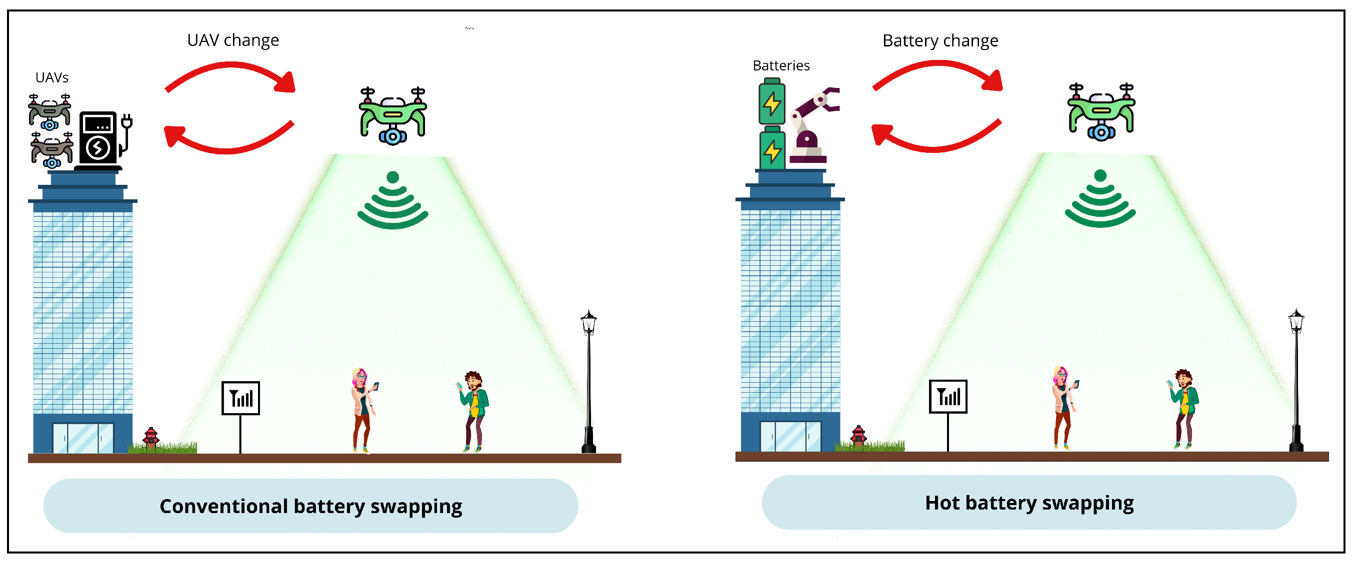
2.3.2. Battery Swapping
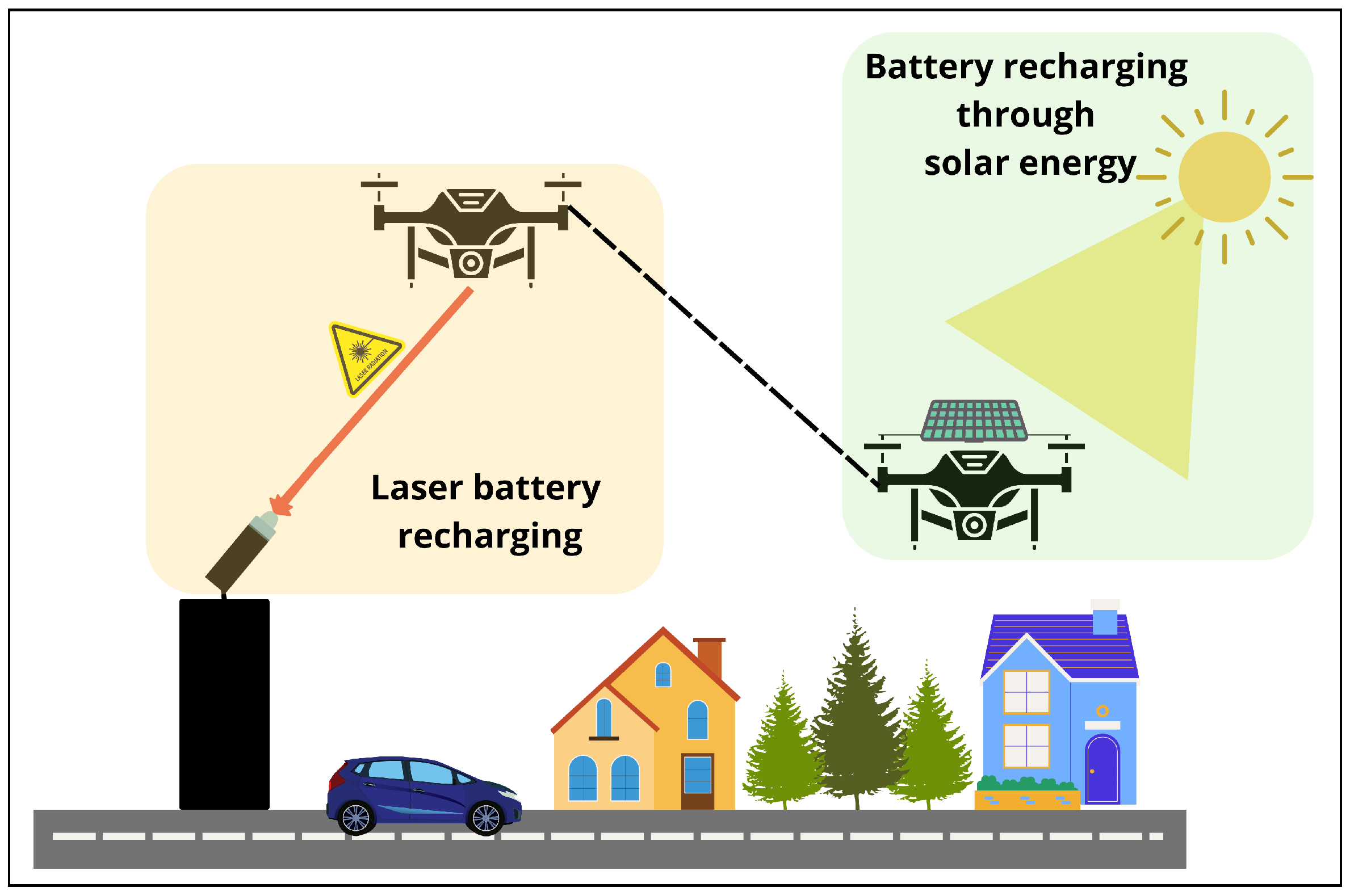
2.3.3. Wireless Recharging
2.3.4. Solar Energy
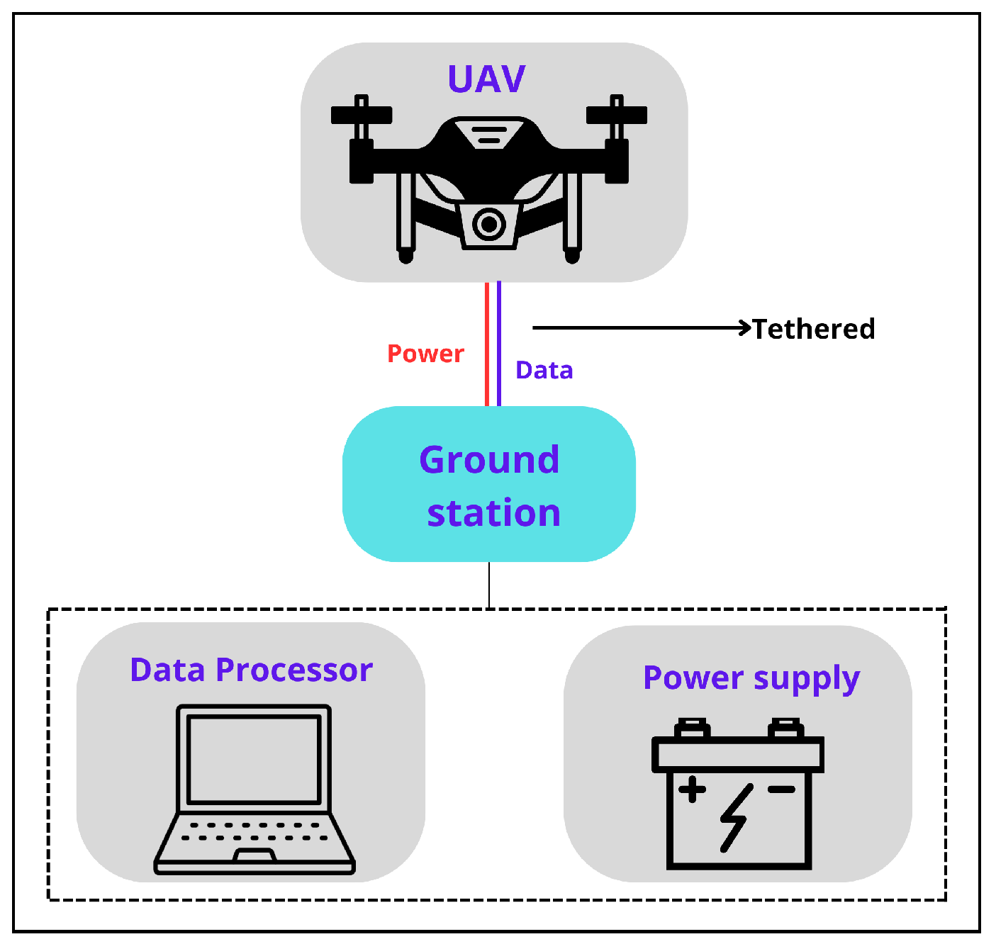
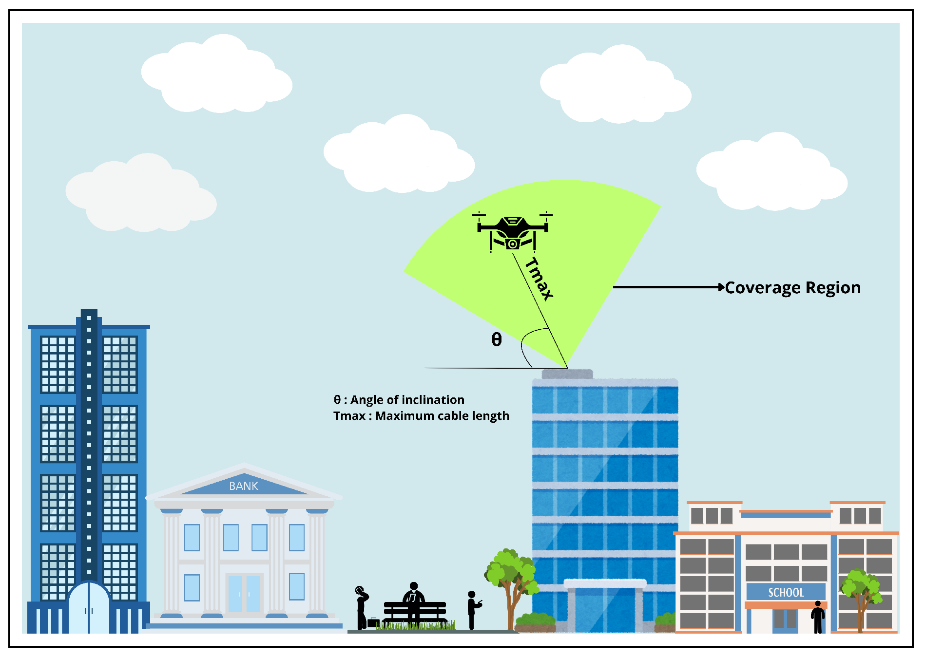
2.4. Tethered UAV
3. Methodology
3.1. Requirements Analysis
- Single-board computer: This device is essential for implementing an IP-based communication system, so it must support the installation and efficient execution of the required software. It must create a wireless network to ensure data transmission, have connectivity interfaces such as Wi-Fi to establish links with other devices, and have a compact and lightweight design, ideal for placement inside the UAV. It must also be energy-efficient to ensure greater autonomy during system operation.
- IP telephony software: Open-source software is required to provide a suitable interface for configuring the IP telephony-based communication system. This software must be compatible with the operating system of the selected device and have detailed documentation to facilitate installation and customization.
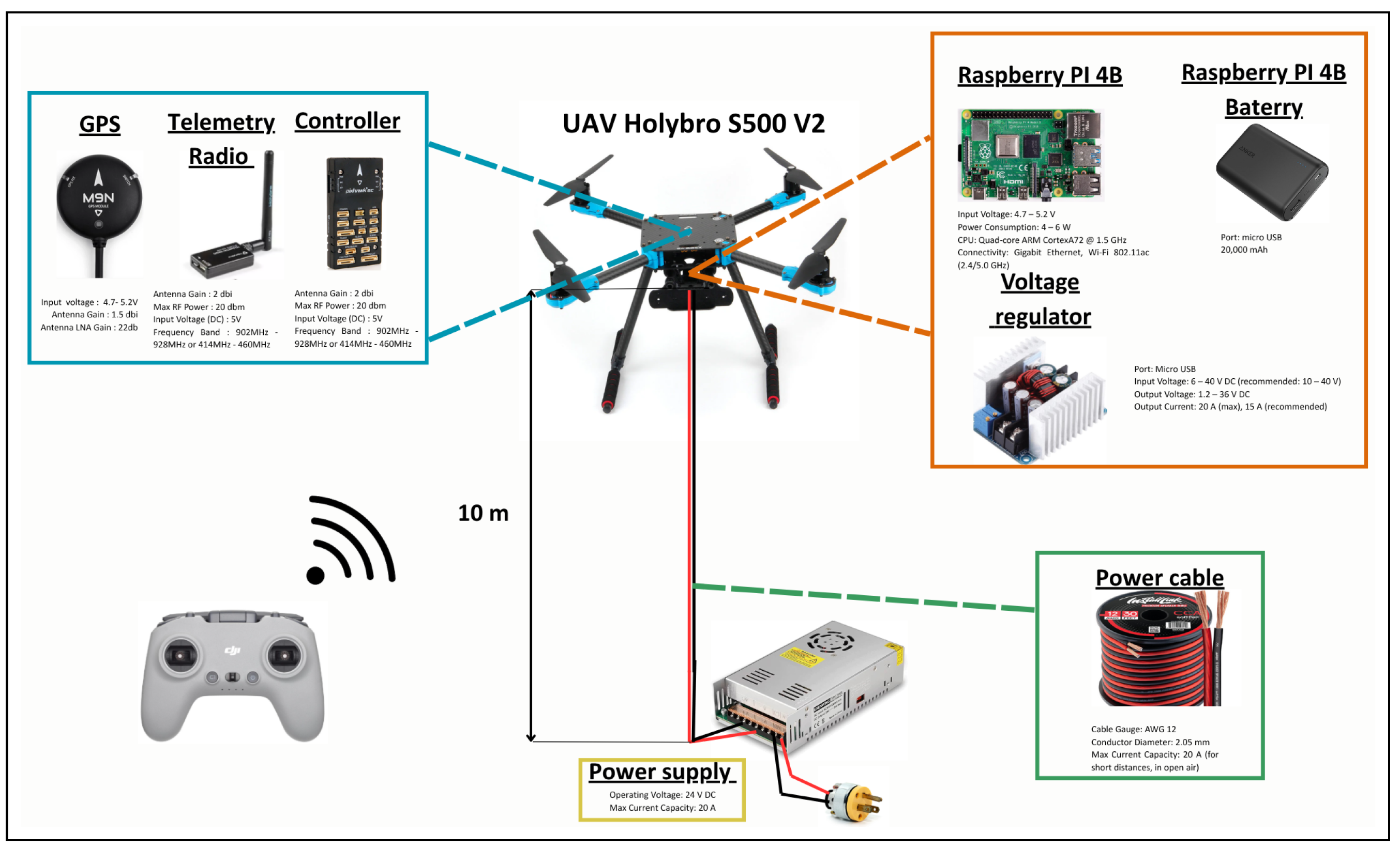
- UAV: A lightweight UAV of simple design must be connected to a ground power supply system via a cable, significantly increasing flight time. This UAV must be capable of carrying a payload of approximately 1.5 kg to support the single-board computer, its battery, and the associated power cable. It must also be equipped with an integrated control system and a GPS module to ensure stable and controlled navigation during operation. It must also include a remote control for ease of operation and real-time monitoring, allowing in-flight adjustments.
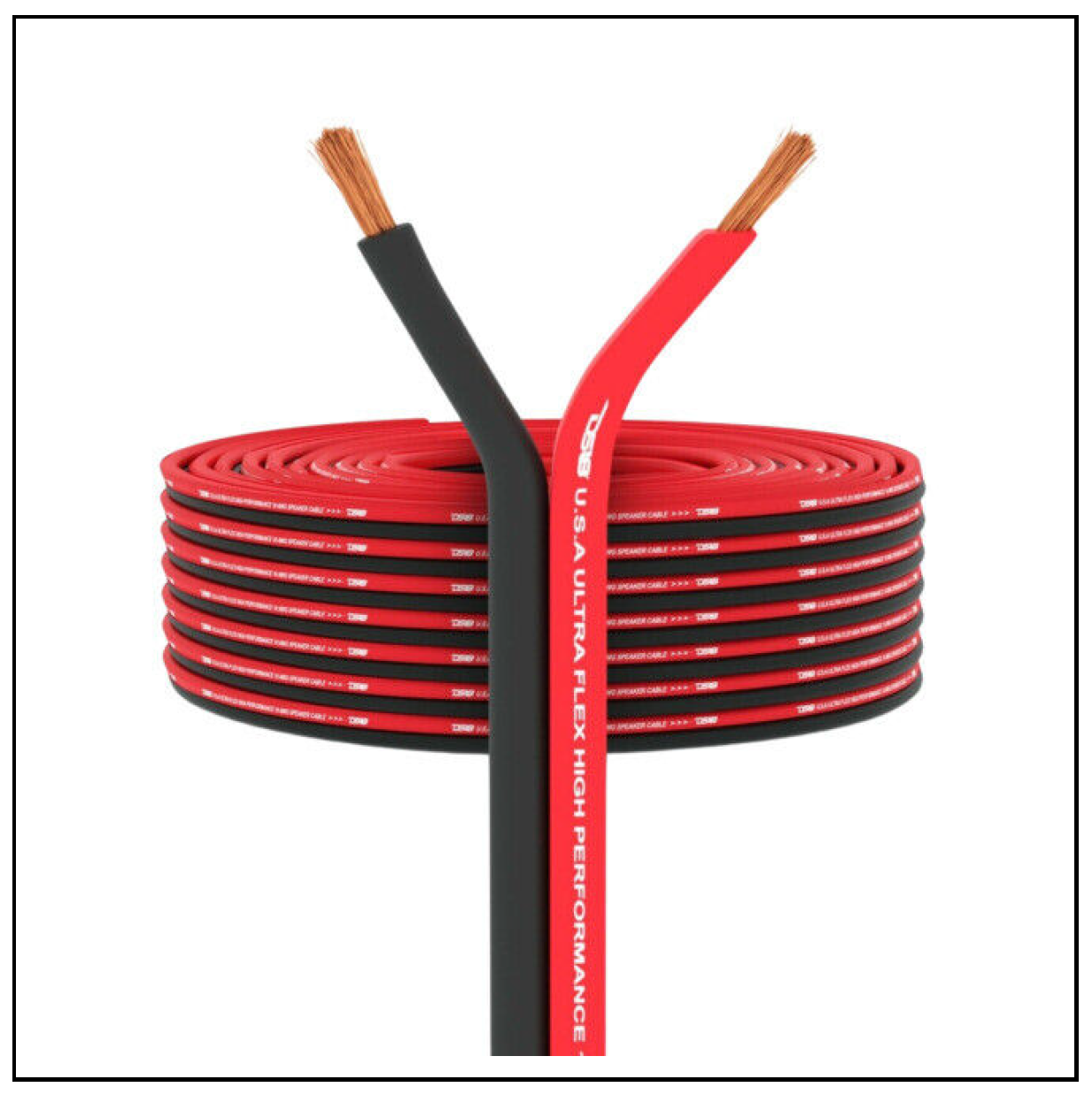
- Power supply system: A ground-based power supply is required to allow the UAV to operate for an extended time. The proposed UAV-enabled communications system assumes the availability of a power grid (AC voltage), which feeds the power supply located at the GCS. In a future approach, the entire system could be portable and entirely battery-powered, as detailed in our previous work [30]. The power supply considered in the prototype must provide a constant voltage and current suitable for operating the UAV. In addition, it is crucial to select an appropriate cable to carry power between the power supply and the UAV, which must not only be capable of carrying the required voltage and current but also have an appropriate gauge to ensure the stability of the power supply, considering an objective distance of approximately 10 m. The cable should be lightweight to minimize the additional load on the UAV, thus optimizing its flight capability.
3.2. Elements for the Prototype
3.2.1. Comparative Analysis and Selection of Single-Board Computers
3.2.2. Comparative Analysis and Selection of IP Telephony Software
3.2.3. Implementation of IP Telephony System
- Installation of the RasPBX operating system: A microSD card with an SD adapter is required to perform the installation. The minimum requirement for the card is a capacity of at least 8 GB, which is necessary to guarantee the correct functioning of the service to be installed. The microSD card must then be inserted into a computer. Next, the RasPBX operating system image must be downloaded. The latest version available is raspbx-10-10-2020, compatible with Raspberry Pi 4, 3, and 2 [34]. To begin with the configuration, follow the steps below:
- (a)
- Download the RasPBX image at [34].
- (b)
- Use the Win32 Disk Imager tool to copy the image to the SD card.
- (c)
- Create an empty text file with the name ’ssh’ and save it on the SD card.
Once the image has been written to the SD card, it is inserted into the Raspberry Pi and connected to the power supply. The Advanced IP Scanner tool is then used to identify the network generated by the Raspberry Pi (specifically, its IP address), which is available for download at [35]. With this information, the computer terminal is accessed, and a remote connection to the Raspberry Pi is established using the SSH protocol, which facilitates remote administration of the device. During the SSH connection process, a password is requested; the default password is raspberry. - Operating system upgrade: To avoid unwanted updates in the PHP repository and prevent possible errors during the system update, the command Listing 1 must be run. With the commands shown in Listing 2, the system is updated correctly without generating problems.
Listing 1. Command to edit the APT source file for PHP. ![Futureinternet 17 00273 i001]()
Listing 2. Commands to update the system. ![Futureinternet 17 00273 i002]()
- Creation of the access point: The Raspberry Pi must establish its wireless network in the proposed prototype. The programs hostapd and dnsmasq are used to do this. Hostapd allows the Raspberry Pi to function as an access point. In contrast, dnsmasq provides the services of DNS and DHCP, taking care of assigning IP addresses to the devices that connect to the network [36]. The commands in Listing 3 must be executed to install both programs.
Listing 3. Commands to install hostapd and dnsmasq. ![Futureinternet 17 00273 i003]() Once hostapd is installed, it must be configured to function as an access point and allow the Raspberry Pi to provide a wireless network. To perform this configuration, the hostapd configuration file must be accessed using the command in Listing 4.
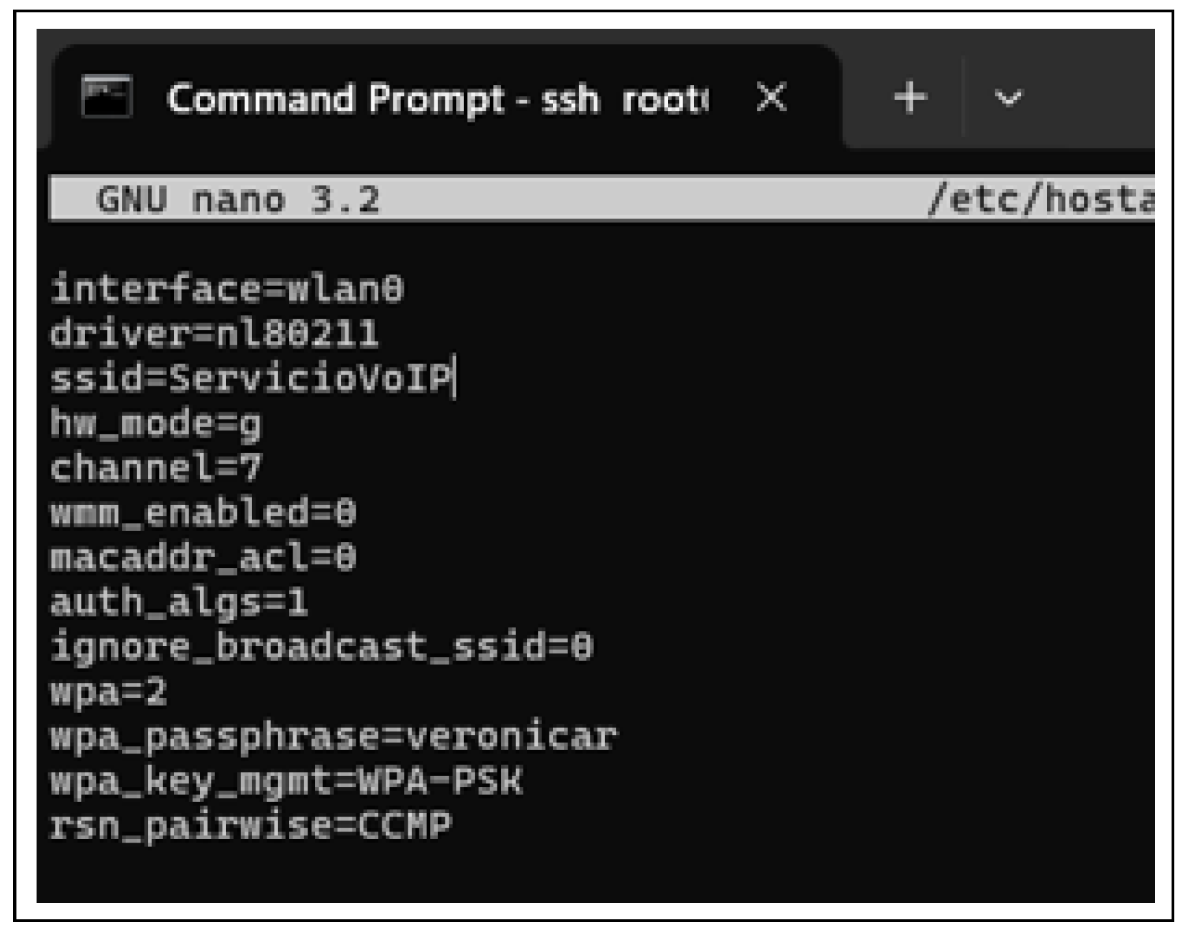
Once hostapd is installed, it must be configured to function as an access point and allow the Raspberry Pi to provide a wireless network. To perform this configuration, the hostapd configuration file must be accessed using the command in Listing 4.Listing 4. Hostapd configuration file. ![Futureinternet 17 00273 i004]() Inside the configuration file, it is necessary to define the specific parameters to establish the network access point. For example, a user can assign the network name (SSID) as “ServiceVoIp” and set the password as “veronicar”. To do this, the following lines should be added to the file as shown in Figure 6. Furthermore, the configuration file must be configured at startup to ensure that hostapd uses the /etc/hostapd/hostapd.conf. To do this, the default hostapd configuration file must be opened with the command in Listing 5, and inside the file, the following line must be added:DAEMON_CONF=“/etc/hostapd/hostapd.conf”
Inside the configuration file, it is necessary to define the specific parameters to establish the network access point. For example, a user can assign the network name (SSID) as “ServiceVoIp” and set the password as “veronicar”. To do this, the following lines should be added to the file as shown in Figure 6. Furthermore, the configuration file must be configured at startup to ensure that hostapd uses the /etc/hostapd/hostapd.conf. To do this, the default hostapd configuration file must be opened with the command in Listing 5, and inside the file, the following line must be added:DAEMON_CONF=“/etc/hostapd/hostapd.conf”Listing 5. Default hostapd configuration file. ![Futureinternet 17 00273 i005]()
- DHCP server configuration: The DHCP server is essential for automatically assigning IP addresses to devices connecting to the network. To configure it, the user must access the corresponding file using the command in Listing 6 and add the line indicated in Listing 7.
Listing 6. Command to edit the DHCP server configuration. ![Futureinternet 17 00273 i006]()
Listing 7. Static IP configuration for the wlan0 interface. ![Futureinternet 17 00273 i007]()
- Dnsmasq configuration: In the proposed prototype, dnsmasq is used to manage IP address allocation and provide name resolution services on the wireless network created by the Raspberry Pi. First, the command in Listing 8 is executed to back up the configuration. Then, the dnsmasq configuration file is edited with the command in Listing 9, and the address range is set using the command in Listing 10.
Listing 8. Command to back up the original dnsmasq configuration file. ![Futureinternet 17 00273 i008]()
Listing 9. Command to edit the dnsmasq configuration file. ![Futureinternet 17 00273 i009]()
Listing 10. DHCP address range configuration for the wlan0 interface. ![Futureinternet 17 00273 i010]()
- Routing and NAT enablement: Several system parameters must be configured to enable routing and NAT on the Raspberry Pi. First, the configuration file sysctl.conf is moved and backed up with the command in Listing 11. Next, to enable IPv4 packet forwarding, the command in Listing 12 must be executed. Finally, iptables is configured to enable the NAT with the command in Listing 13, and the configuration must be saved.
Listing 11. Command to move and backup the sysctl.conf configuration file. ![Futureinternet 17 00273 i011]()
Listing 12. Enabling IPv4 packet forwarding in the system. ![Futureinternet 17 00273 i012]()
Listing 13. Command to enable NAT and save the iptables configuration. ![Futureinternet 17 00273 i013]()
- Saving the iptables rules’ configuration: To ensure that firewall rules persist after reboot, the /etc/rc.local file is edited by adding the command to restore the iptables rules on startup. The command in Listing 14 is used to open the file. Then, the line shown in Listing 15 is inserted just before the exit 0 statement.
Listing 14. Command to edit the /etc/rc.local file. ![Futureinternet 17 00273 i014]()
Listing 15. Line to restore the iptables rules at startup. ![Futureinternet 17 00273 i015]()
- Restart services: The dnsmasq service is restarted to apply new configurations, as shown in Listing 16.
Listing 16. Command to restart the dnsmasq service. ![Futureinternet 17 00273 i016]()
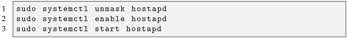
- Activation and initialization of the hostapd service: The following commands are executed to unmask, enable, and start hostapd, ensuring the wireless access point operates correctly, as shown in Listing 17.
Listing 17. Commands to activate and start the hostapd service. ![Futureinternet 17 00273 i017]()
- Verifying current iptables rules: The currently active firewall rules are checked with the command in Listing 18.
Listing 18. Command to list the current iptables rules with details. ![Futureinternet 17 00273 i018]()
- Adding rules to allow SIP and RTP traffic: Firewall rules to permit traffic on UDP ports 5060 (SIP) and 10,000–20,000 (RTP) are inserted, as shown in Listing 19.
Listing 19. Commands to add iptables rules for SIP and RTP traffic. ![Futureinternet 17 00273 i019]()
- Saving the current iptables rules: The active iptables rules are maintained by saving them to the configuration file with the command in Listing 20.
Listing 20. Command to save iptables rules’ configuration. ![Futureinternet 17 00273 i020]()
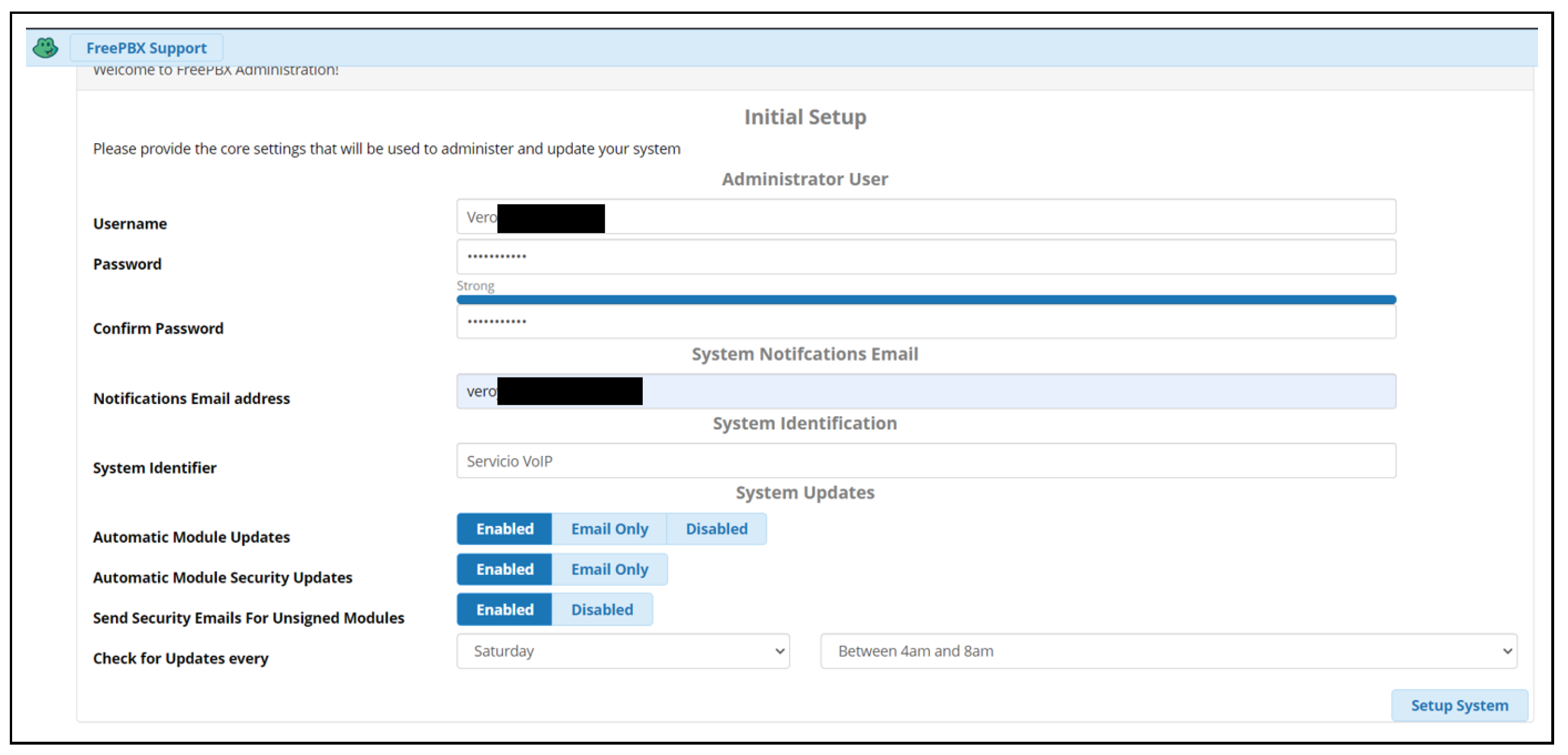
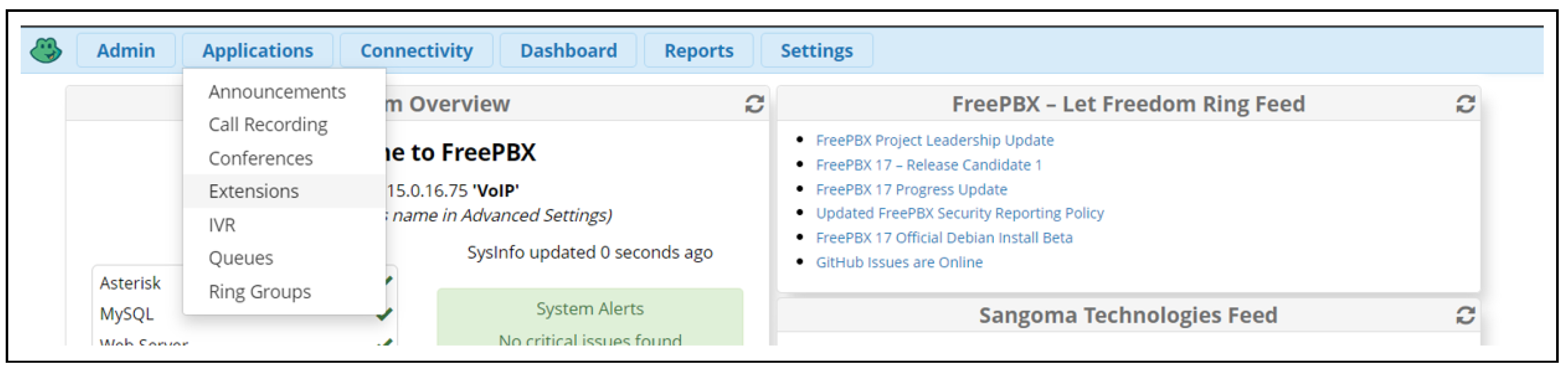
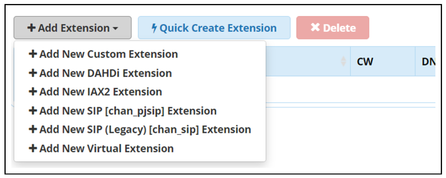
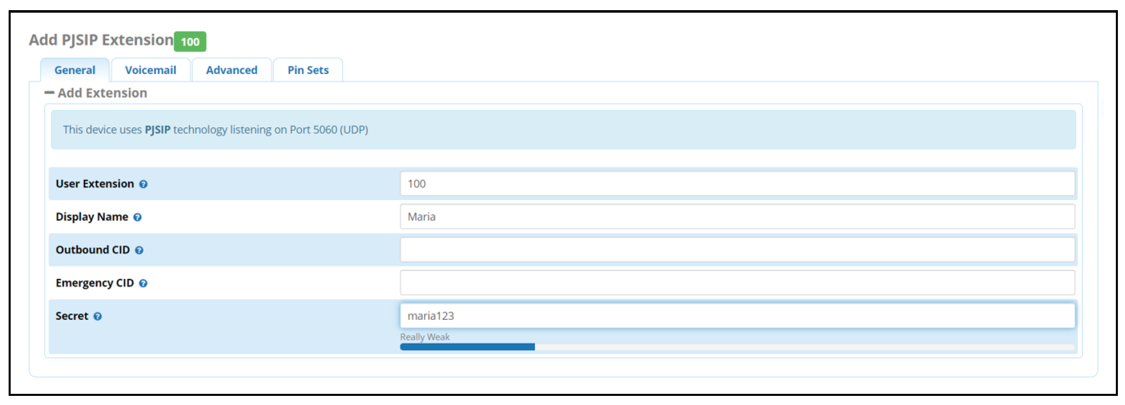
- IP telephony system configuration: An access point is established with the above configurations. The next step is to connect to this network from a computer and log in to the system through the browser using the Raspberry Pi’s IP address. In FreePBX, the initial configurations of the service are set, which include creating a user, assigning a password, setting up an email for notifications, and naming the service. In addition, the day and time for updates are configured, as shown in Figure 7.When logged in as an administrator, the home screen is displayed as shown in Figure 8. Then, the user must select the Applications option, click on Extensions, and choose the extension type, as shown in Figure 9.Figure 10 shows the process of configuring an extension, where the user must enter the extension number, the user name, and the corresponding password. Two users were created for this prototype: (i) Maria and (ii) Pedro. Maria was assigned extension 100, while Pedro was assigned extension 101. Once the configuration was complete, all extensions created could be verified, as shown in Figure 11.
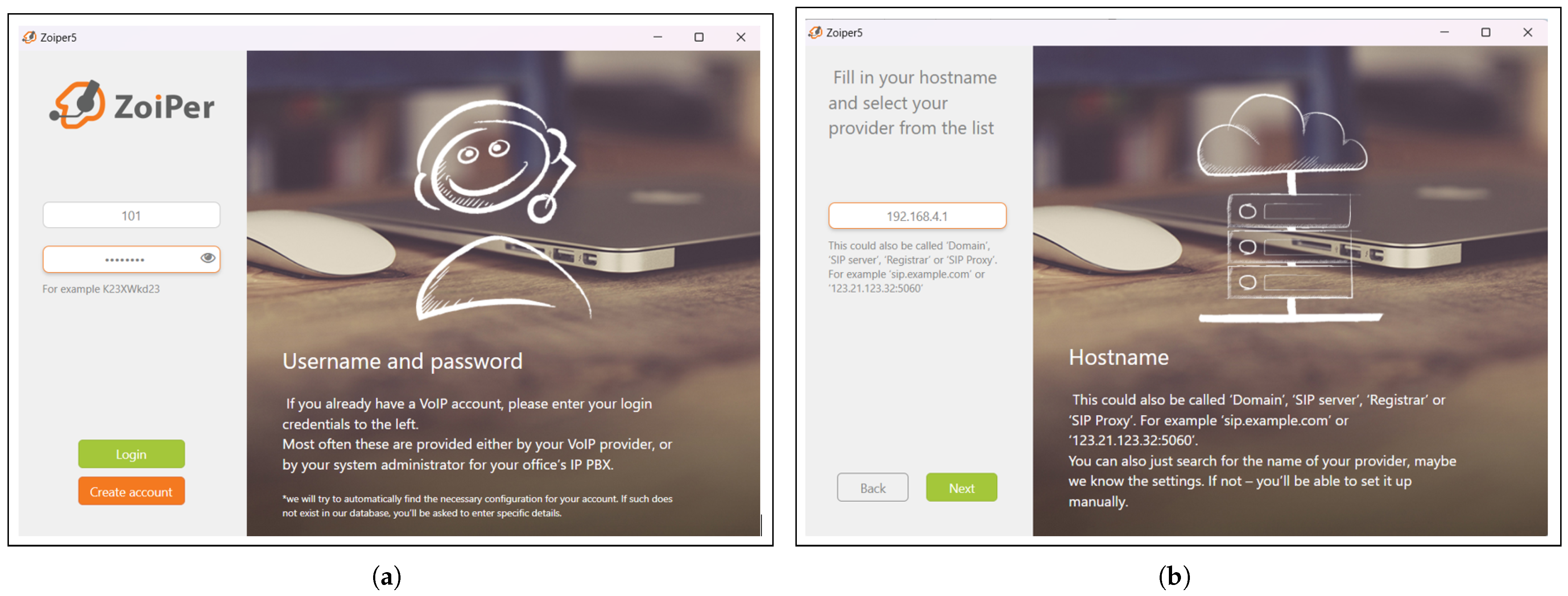
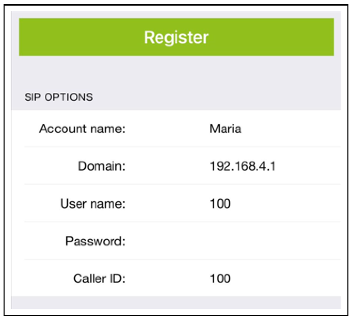
- Download and configuration of Zoiper: Zoiper is available for Linux, Microsoft Windows, and macOS operating systems. On mobile devices, it can be downloaded for Android and iOS. Once the softphone was installed, tests were conducted by configuring two users with the same data registered in FreePBX. For example, for the user Maria, the extension 100, the corresponding password, and the IP address of the device providing the IP service (i.e., the IP of the Raspberry Pi (192.168.4.1)) were assigned. Similarly, for the user Pedro, extension 101 was configured along with its key. These configurations are shown in Figure 12a and Figure 12b, respectively. This step concludes with the installation and configuration of the IP service on the Raspberry Pi. To perform the tests, at least two devices are required, such as a computer or a cell phone, which will allow making calls and verifying the correct connection.


3.2.4. UAV
3.2.5. Power System Analysis and Design
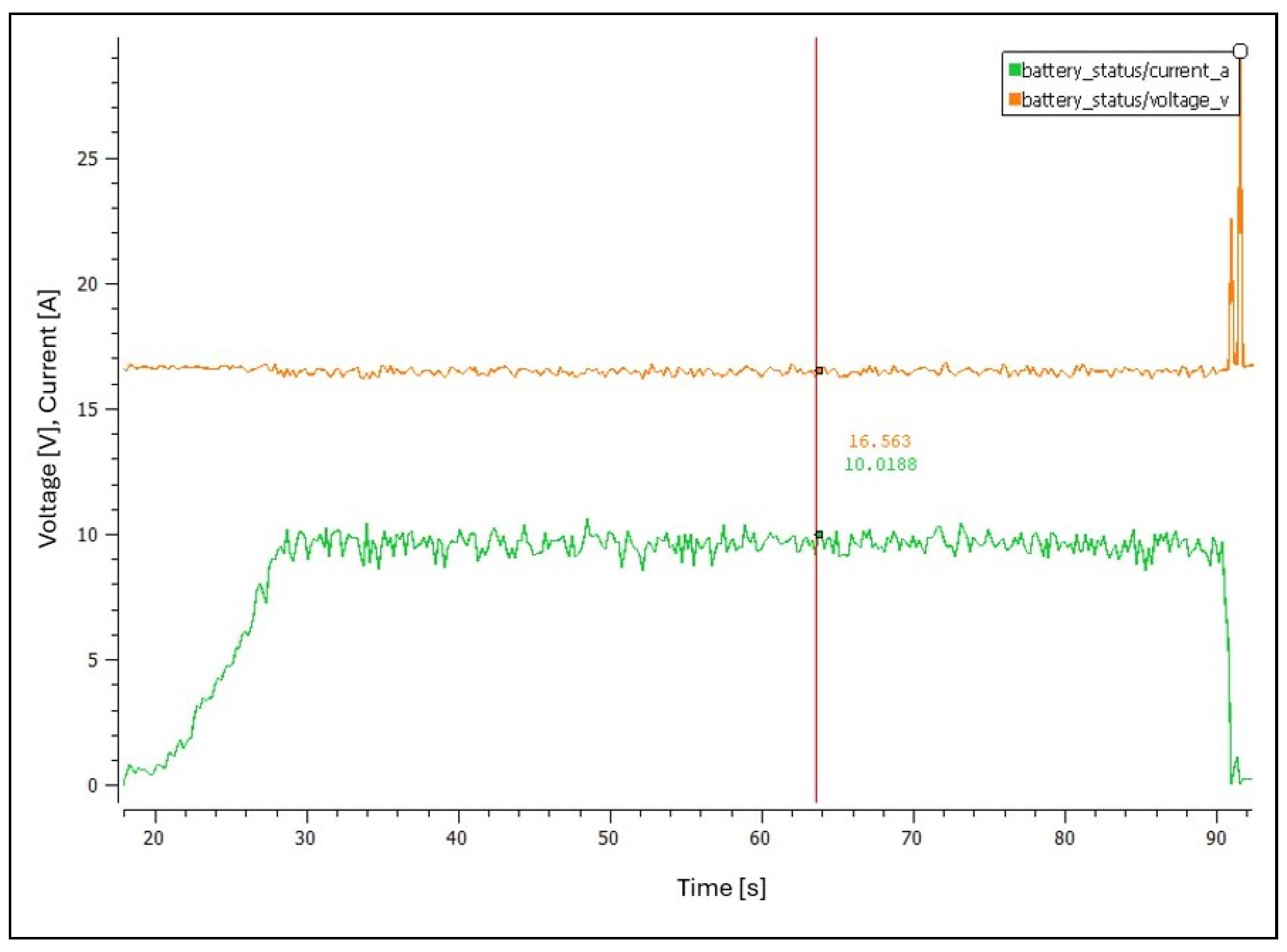
- Analysis of UAV energy consumption: Table 5 shows that for a payload of 1.3 kg, the power consumption is approximately 16 V and 16.37 A. However, these values may vary depending on the weight carried, weather conditions, and other elements that influence system performance. Therefore, evaluating how power consumption varies as a function of the weight being transported is essential for selecting the right components for efficient UAV operation. For this purpose, initial tests were performed using a 1500 mAh, 4S, and 120C spec battery, as shown in Figure 14.

- Power supply selection and characteristics: Based on the tests performed to determine the UAV power supply requirements, a voltage of 16 V and a current of 20 A were established as operating parameters. To meet these conditions, a switch-mode power supply was selected, whose specifications are presented in Table 10 and illustrated in Figure 19. Because this supply provides a higher voltage than necessary, we chose to use a step-down voltage regulator, as shown in Figure 20, to lower the voltage to 16 V. Additionally, this regulator can continuously handle up to 20 A, thus satisfying the system requirements.


- Calculations for cable size determination: To select the appropriate cable, the specific energy parameters of the design are considered and are detailed below.
- -
- Voltage required by the UAV: 16 V.
- -
- Current required: 20 A.
- -
- Distance between the power supply and the UAV: 10 m.
- -
- Conductor material: Copper.
- R: Resistance, measured in ohms ().
- : Resistivity, measured in ohm-meters ().
- L: Length, measured in meters (m).
- A: Cross-sectional area, measured in square meters ().
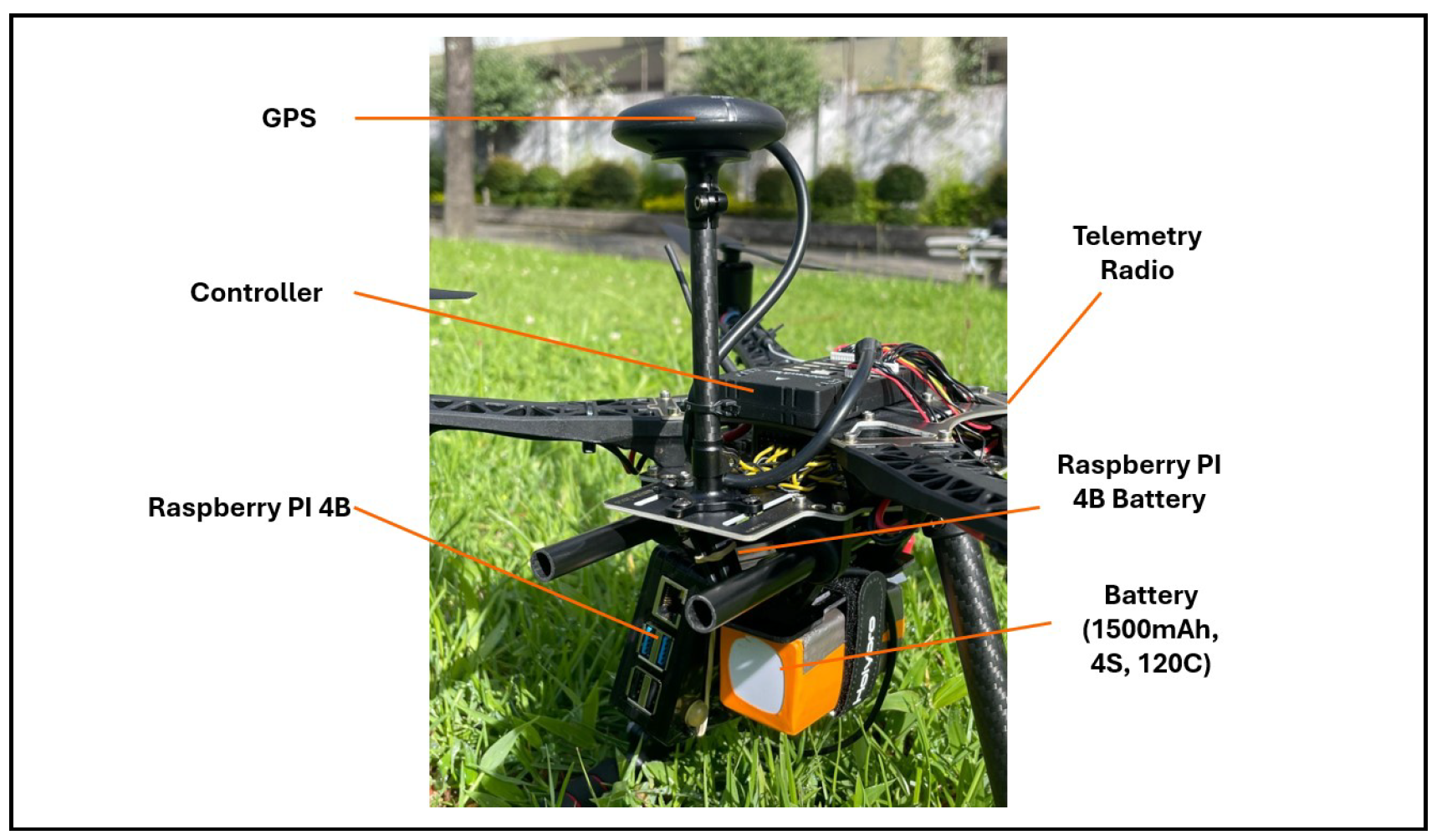
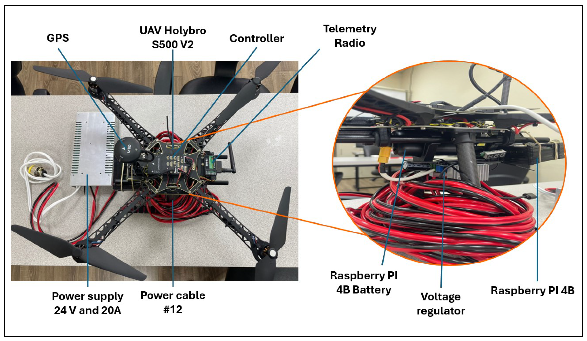
3.2.6. Prototype Structure
3.2.7. Costs of Prototype Elements
4. Results
4.1. Prototype Testing in a Closed Environment
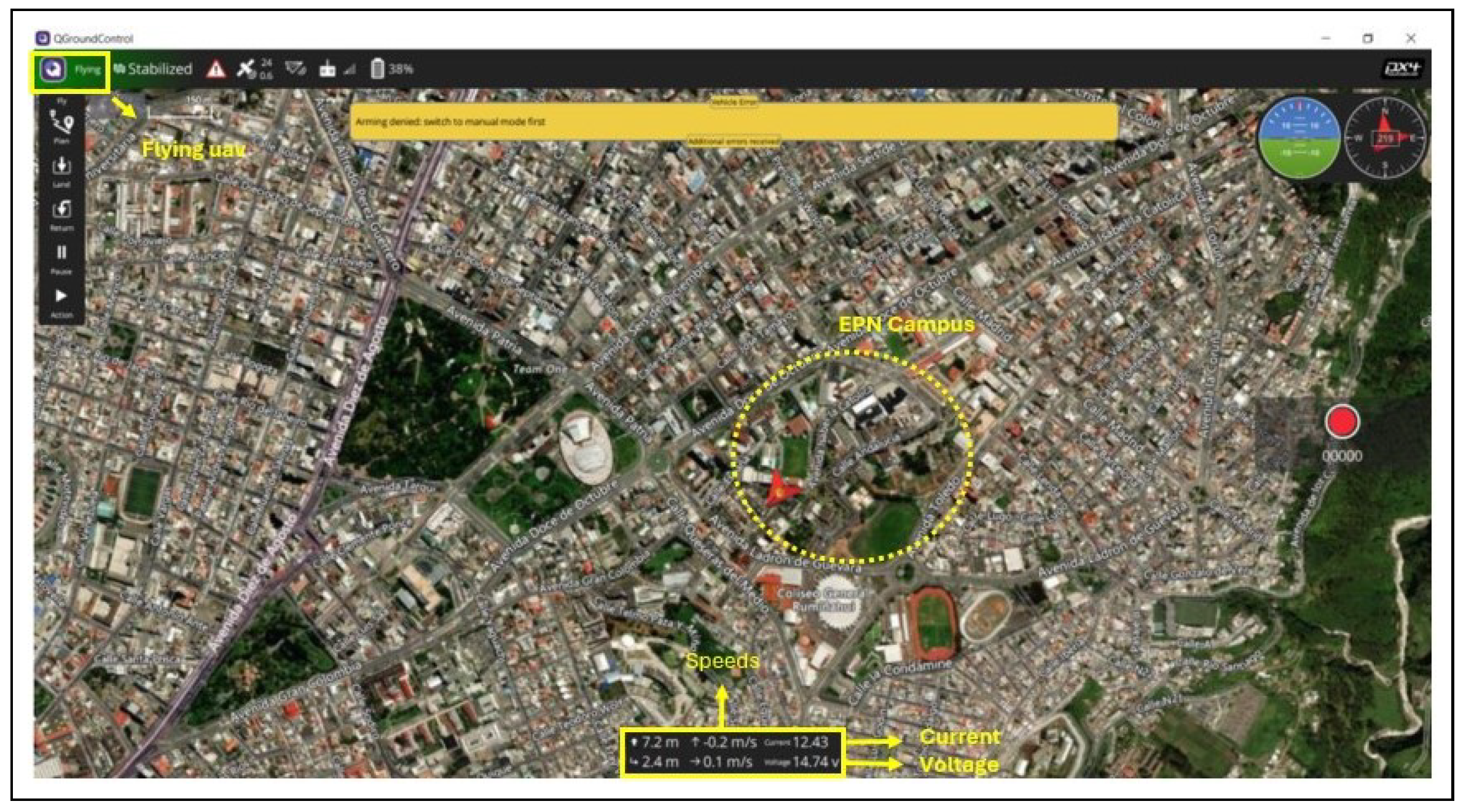
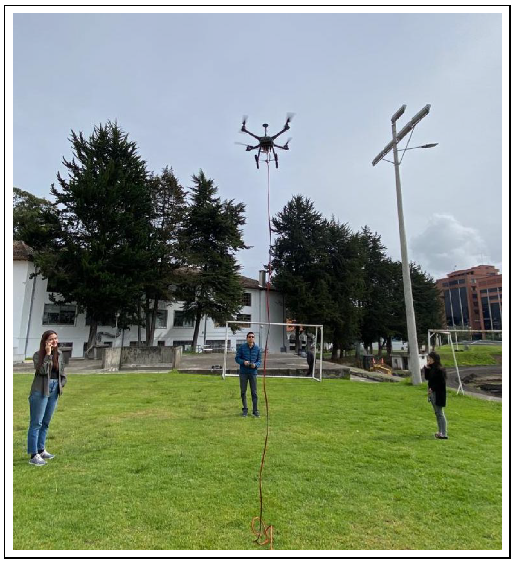
4.2. Prototype Testing in an Open Environment
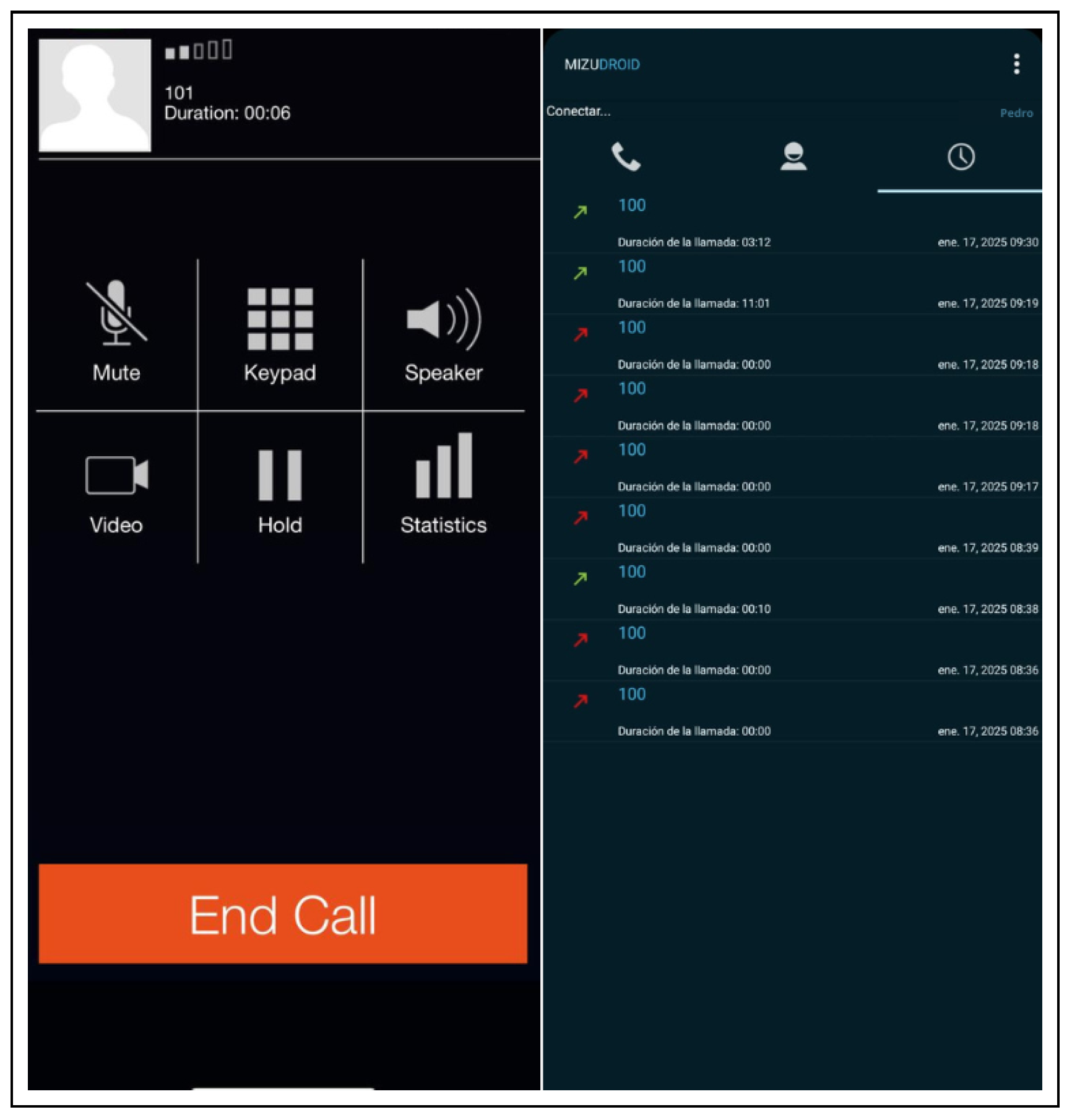
4.2.1. IP Telephony Service Performance Analysis
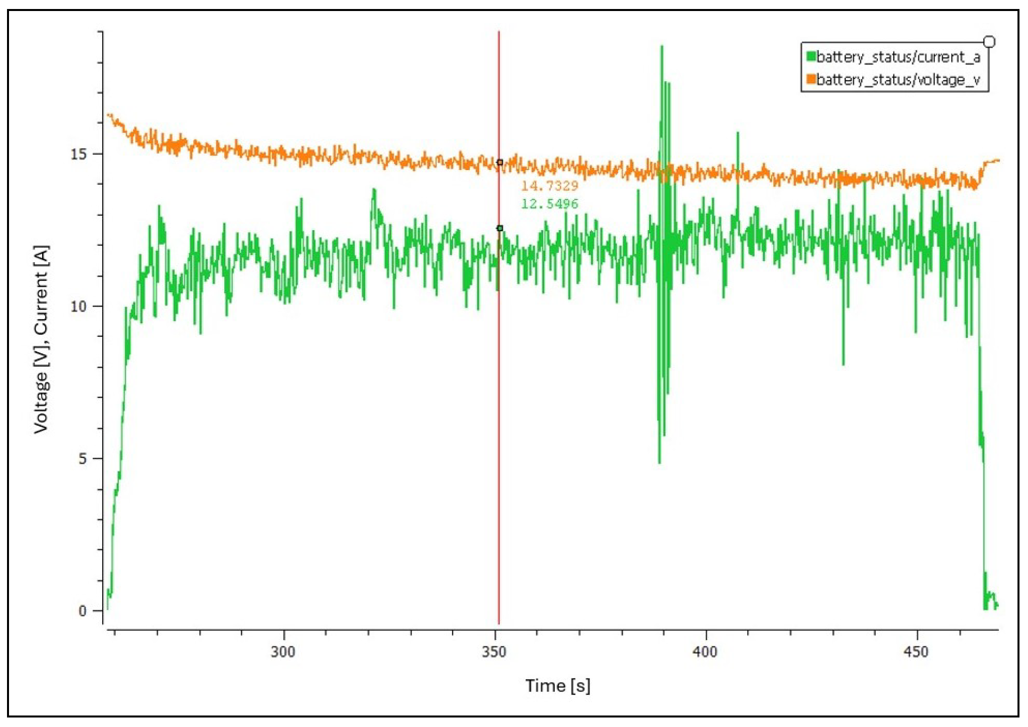
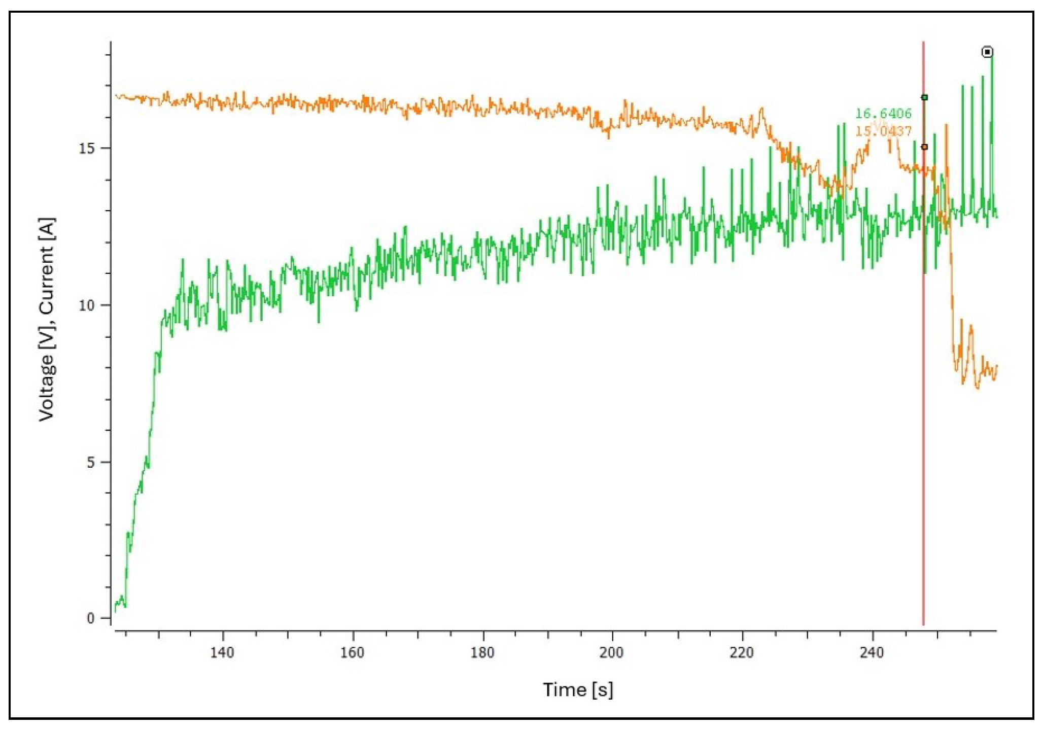
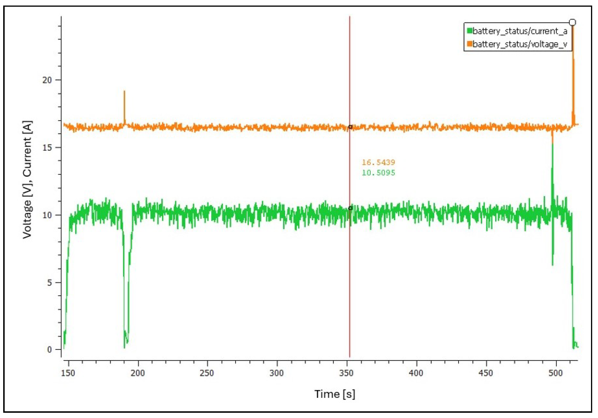
4.2.2. Power System Analysis
4.3. Data Obtained on the Different Flights
5. Conclusions
Author Contributions
Funding
Institutional Review Board Statement
Informed Consent Statement
Data Availability Statement
Acknowledgments
Conflicts of Interest
Abbreviations
| BS | Base station |
| CPT | Capacitive power transfer |
| GSC | Ground control station |
| IoT | Internet of Things |
| IPT | Inductive power transfer |
| MRC | Magnetic resonance coupling |
| LiPo | Lithium polymer |
| T-UAV | Tethered UAV |
| UAV | Unmanned aerial vehicle |
References
- Kim, J.; Kim, S.; Ju, C.; Son, H.I. Unmanned Aerial Vehicles in Agriculture: A Review of Perspective of Platform, Control, and Applications. IEEE Access 2019, 7, 105100–105115. [Google Scholar] [CrossRef]
- Reddy Maddikunta, P.K.; Hakak, S.; Alazab, M.; Bhattacharya, S.; Gadekallu, T.R.; Khan, W.Z.; Pham, Q.V. Unmanned Aerial Vehicles in Smart Agriculture: Applications, Requirements, and Challenges. IEEE Sens. J. 2021, 21, 17608–17619. [Google Scholar] [CrossRef]
- Yoo, W.; Yu, E.; Jung, J. Drone delivery: Factors affecting the public’s attitude and intention to adopt. Telemat. Inform. 2018, 35, 1687–1700. [Google Scholar] [CrossRef]
- Macrina, G.; Di Puglia Pugliese, L.; Guerriero, F.; Laporte, G. Drone-aided routing: A literature review. Transp. Res. Part Emerg. Technol. 2020, 120, 102762. [Google Scholar] [CrossRef]
- Zeng, Y.; Zhang, R. Energy-Efficient UAV Communication with Trajectory Optimization. IEEE Trans. Wirel. Commun. 2017, 16, 3747–3760. [Google Scholar] [CrossRef]
- Bushnaq, O.M.; Kishk, M.A.; Celik, A.; Alouini, M.S.; Al-Naffouri, T.Y. Optimal Deployment of Tethered Drones for Maximum Cellular Coverage in User Clusters. IEEE Trans. Wirel. Commun. 2021, 20, 2092–2108. [Google Scholar] [CrossRef]
- Bertran, E.; Sanchez-Cerda, A. On the Tradeoff Between Electrical Power Consumption and Flight Performance in Fixed-Wing UAV Autopilots. IEEE Trans. Veh. Technol. 2016, 65, 8832–8840. [Google Scholar] [CrossRef]
- Nguyen, M.T.; Nguyen, C.V.; Truong, L.H.; Le, A.M.; Quyen, T.V.; Masaracchia, A.; Teague, K.A. Electromagnetic Field Based WPT Technologies for UAVs: A Comprehensive Survey. Electronics 2020, 9, 461. [Google Scholar] [CrossRef]
- Monteiro, M.; Stari, C.; Cabeza, C.; Martí, A.C. Simple Physics behind the Flight of a Drone. Phys. Educ. 2022, 57, 025029. [Google Scholar] [CrossRef]
- Sanchez-Aguero, V.; Valera, F.; Vidal, I.; Tipantuña, C.; Hesselbach, X. Energy-Aware Management in Multi-UAV Deployments: Modelling and Strategies. Sensors 2020, 20, 2791. [Google Scholar] [CrossRef]
- Bianchi, D.; Borri, A.; Di Gennaro, S.; Preziuso, M. UAV trajectory control with rule-based minimum-energy reference generation. In Proceedings of the 2022 European Control Conference (ECC), London, UK, 12–15 July 2022; pp. 1497–1502. [Google Scholar] [CrossRef]
- Mehmood, A.; Iqbal, Z.; Shah, A.A.; Maple, C.; Lloret, J. An Intelligent Cluster-Based Communication System for Multi-Unmanned Aerial Vehicles for Searching and Rescuing. Electronics 2023, 12, 607. [Google Scholar] [CrossRef]
- Alexan, W.; Aly, L.; Korayem, Y.; Gabr, M.; El-Damak, D.; Fathy, A.; Mansour, H.A.A. Secure Communication of Military Reconnaissance Images Over UAV-Assisted Relay Networks. IEEE Access 2024, 12, 78589–78610. [Google Scholar] [CrossRef]
- Nowakowski, M.; Berger, G.S.; Braun, J.; Mendes, J.a.; Bonzatto Junior, L.; Lima, J. Advance Reconnaissance of UGV Path Planning Using Unmanned Aerial Vehicle to Carry Our Mission in Unknown Environment. In Robot 2023: Proceedings of the Sixth Iberian Robotics Conference, Coimbra, Portugal, 22–24 November 2023; Springer: Berlin/Heidelberg, Germany, 2023; pp. 50–61. [Google Scholar]
- Laghari, A.A.; Jumani, A.K.; Laghari, R.A.; Li, H.; Karim, S.; Khan, A.A. Unmanned aerial vehicles advances in object detection and communication security review. Cogn. Robot. 2024, 4, 128–141. [Google Scholar] [CrossRef]
- Cook, K.L.B. The Silent Force Multiplier: The History and Role of UAVs in Warfare. In Proceedings of the 2007 IEEE Aerospace Conference, Big Sky, MT, USA, 3–10 March 2007; pp. 1–7. [Google Scholar] [CrossRef]
- Marques, M.N.; Magalhães, S.A.; Dos Santos, F.N.; Mendonça, H.S. Tethered Unmanned Aerial Vehicles—A Systematic Review. Robotics 2023, 12, 117. [Google Scholar] [CrossRef]
- Mercatali, E. Feasibility Study for the Propulsion System of a Tethered UAV. Ph.D. Thesis, Politecnico di Torino, Turin, Italy, 2019. [Google Scholar]
- Chittoor, P.K.; Chokkalingam, B.; Mihet-Popa, L. A Review on UAV Wireless Charging: Fundamentals, Applications, Charging Techniques and Standards. IEEE Access 2021, 9, 69235–69266. [Google Scholar] [CrossRef]
- Boukoberine, M.; Zhou, Z.; Benbouzid, M. A Critical Review on Unmanned Aerial Vehicles Power Supply and Energy Management: Solutions, Strategies, and Prospects. Appl. Energy 2019, 255, 113823. [Google Scholar] [CrossRef]
- Jin, W.; Yang, J.; Fang, Y.; Feng, W. Research on Application and Deployment of UAV in Emergency Response. In Proceedings of the 2020 IEEE 10th international conference on electronics information and emergency communication (ICEIEC), Beijing, China, 17–19 July 2020; pp. 277–280. [Google Scholar] [CrossRef]
- Abubakar, A.; Ahmad, I.; Omeke, K.; Ozturk, M.; Öztürk, C.; Abdel-Salam, A.; Mollel, M.; Abbasi, Q.; Hussain, S.; Imran, M. A Survey on Energy Optimization Techniques in UAV-Based Cellular Networks: From Conventional to Machine Learning Approaches. Drones 2023, 7, 214. [Google Scholar] [CrossRef]
- Singh, S.; Malik, A.; Kumar, R.; Singh, P. A proficient data gathering technique for unmanned aerial vehicle-enabled heterogeneous wireless sensor networks. Int. J. Commun. Syst. 2021, 34, e4956. [Google Scholar] [CrossRef]
- Liu, Y.; Dai, H.N.; Wang, H.; Imran, M.; Wang, X.; Shoaib, M. UAV-enabled data acquisition scheme with directional wireless energy transfer for Internet of Things. Comput. Commun. 2020, 155, 184–196. [Google Scholar] [CrossRef]
- Sanike, A.; Subramanyam, A.; Reddy, S.S.S.; RaghuRam, G. Load balancing technique to handle the congestion in the communication networks. In Proceedings of the 2015 Conference on Power, Control, Communication and Computational Technologies for Sustainable Growth (PCCCTSG), Kurnool, India, 11–12 December 2015; pp. 289–293. [Google Scholar] [CrossRef]
- Hassanalian, M.; Abdelkefi, A. Classifications, applications, and design challenges of drones: A review. Prog. Aerosp. Sci. 2017, 91, 99–131. [Google Scholar] [CrossRef]
- Gao, Y.; Qiao, Z.; Pei, X.; Wu, G.; Bai, Y. Design of Energy-Management Strategy for Solar-Powered UAV. Sustainability 2023, 15, 4972. [Google Scholar] [CrossRef]
- Kishk, M.A.; Bader, A.; Alouini, M.S. On the 3-D Placement of Airborne Base Stations Using Tethered UAVs. IEEE Trans. Commun. 2020, 68, 5202–5215. [Google Scholar] [CrossRef]
- Kishk, M.; Bader, A.; Alouini, M.S. Aerial Base Station Deployment in 6G Cellular Networks Using Tethered Drones: The Mobility and Endurance Tradeoff. IEEE Veh. Technol. Mag. 2020, 15, 103–111. [Google Scholar] [CrossRef]
- Parra, C.; Tatayo, E.; Paccha, A.; Tipantuña, C.; Carvajal, J. SDR-Based Portable Open-Source GSM/GPRS Network for Emergency Scenarios. In Proceedings of the 2019 Sixth International Conference on eDemocracy & eGovernment (ICEDEG), Quito, Ecuador, 24–26 April 2019; pp. 268–273. [Google Scholar] [CrossRef]
- Hardkernel Co., Ltd. ODROID-C4 Product Page. Available online: https://www.hardkernel.com/shop/odroid-c4/ (accessed on 15 January 2025).
- Guedes, R.J.S. ARDUINO. Available online: https://www3.gobiernodecanarias.org/medusa/ecoblog/rsuagued/arduino/ (accessed on 15 January 2025).
- Pi, R. Raspberry Pi 4 Model B Specifications. Available online: https://www.raspberrypi.com/products/raspberry-pi-4-model-b/specifications/ (accessed on 22 January 2025).
- RasPBX Project. RasPBX—Asterisk for Raspberry Pi. Available online: http://www.raspbx.org/ (accessed on 20 January 2025).
- Famatech Corp. Advanced IP Scanner. Available online: https://www.advanced-ip-scanner.com/es/ (accessed on 20 January 2025).
- Fromaget, P. Turn Your Raspberry Pi into a Wi-Fi Access Point. Available online: https://raspberrytips.es/punto-de-acceso-raspberry-pi/ (accessed on 25 January 2025).
- Holybro. S500 V2 Development Kit. Available online: https://holybro.com/products/s500-v2-development-kit (accessed on 10 January 2025).
- QGroundControl Development Team. QGroundControl—Drone Control—Ground Control Station for Small Air—Land—Water Autonomous Unmanned Systems. Available online: https://qgroundcontrol.com/ (accessed on 20 January 2025).
- Faconti, D. PlotJuggler: Fast, Intuitive and Extensible Time Series Visualization Tool. Available online: https://plotjuggler.io/ (accessed on 20 January 2025).
- Association, N.F.P. National Electrical Code (NEC), 2017th ed.; National Fire Protection Association: Quincy, MA, USA, 2017. [Google Scholar]
- IEC 60204-1:2016; Safety of Machinery—Electrical Equipment of Machines—Part 1: General Requirements. International Electrotechnical Commission: Geneva, Switzerland, 2016. Available online: https://webstore.iec.ch/en/publication/26037 (accessed on 13 April 2025).
- Lifeline. Ground Tether System—LIFELINE—S. Available online: https://www.lifeline-drone.com/product-page/lifeline-tethered-drone-system (accessed on 13 April 2025).


| Characteristics | Ni-Cd | Ni-Mh | LiPo | Li-S |
|---|---|---|---|---|
| Specific energy (Wh/kg) | 40 | 80 | 180 | 350 |
| Energy density (Wh/L) | 100 | 300 | 300 | 350 |
| Specific power (W/kg) | 300 | 900 | 2800 | 600 |
| Company Names | Tether Length | Flight Time |
|---|---|---|
| Equinox Systems | 150 m | 30 days |
| Arial Insights | 120 m | Multiple operation |
| Elistair | 80 m | More than 10 h |
| Features | Raspberry Pi 4B | Arduino Uno | ODROID C4 |
|---|---|---|---|
| Processor | Quad-core Cortex-A72 at 1.5 GHz | ATmega328P (8-bit) | Amlogic S905X3 (Quad-core Cortex-A55 at 2.0 GHz) |
| RAM | 2/4/8 GB LPDDR4 | 256 MB–1 GB | 4 GB DDR4 |
| VoIP Compatibility | Compatible (e.g., Asterisk, FreePBX, FreeSWITCH) | Not compatible | Compatible with Asterisk |
| Wi-Fi Module | Dual-band (2.4/5 GHz)-integrated | External module required | Needs an external adapter |
| Ports and Interfaces | GPIO, USB 2.0/3.0, HDMI, Ethernet | GPIO and USB | GPIO, USB 3.0, HDMI, Ethernet |
| Voltage | 5 V input | 5 V input | 5 V input |
| Power Consumption | 3–5 W | 0.5–1.5 W | 5 W maximum |
| Size and Weight | 85.6 × 56.5 mm, 46 g | 68.6 × 53.4 mm, 25 g | 85 mm × 56 mm × 1.0 mm, 59 g |
| Operating Systems | Raspberry Pi OS, Ubuntu, among others | Arduino IDE | Armbian, Android, Ubuntu, among others |
| Price (USD) | Around $150 | Around $20 | Around $120 |
| Features | 3CX | FreePBX | Asterisk |
|---|---|---|---|
| Open-source | Yes | Yes | Yes |
| Raspberry Pi Compatibility | Compatible | Compatible | Compatible |
| Documentation and Support | Moderate (free version) | Extensive and active | Extensive and active |
| Main Features | Call management, extensions, video calls (limited in free version) | Advanced call management, extensions, IVR | Flexible platform with full support for extensions, IVR, and advanced customization |
| Configuration Type | Requires downloading the Raspberry Pi OS image; installation is complex and achieved via GUI or commands | The software image is directly stored in memory and configured via commands | The Raspberry Pi OS image is downloaded, and the softphone is installed using manual commands |
| Scalability | Moderate (limited free version) | High | Very high |
| Feature | Detail |
|---|---|
| Weight | 1230 g |
| Dimensions | 383 × 385 × 240 mm |
| Maximum payload weight | 1.5 kg |
| Propellers | 4 |
| Recommended voltage for 1.3 kg payload | 16 V |
| Recommended current for 1.3 kg payload | 16.37 A |
| Flight time | 18 min in hover flight with a 5000 mAh battery |
| Feature | Detail |
|---|---|
| Speed | 480 MHz |
| Flash memory | 2 MB |
| RAM | 1 MB |
| Weight | 34.6 g |
| Feature | Detail |
|---|---|
| Reception sensitivity | −117 dBm |
| Communication | Full-duplex bidirectional via UART TDM interface |
| Dimensions | 28 × 53 × 10.7 mm |
| Maximum output power | 100 mW |
| Power supply voltage | 5 V DC (via USB or JST-GH) |
| Weight | 13.6 g |
| Weight [g] | Voltage [V] | Current [A] |
|---|---|---|
| 1155 | 15.4 | 8.9 |
| 2100 | 15 | 20 |
| Altitude [m] | Voltage [V] | Current [A] |
|---|---|---|
| 1.3 | 14.91 | 11.66 |
| 2.4 | 14.74 | 12.43 |
| Feature | Details |
|---|---|
| Input voltage | 110 V or 220 V |
| Voltage range | 0–24 V |
| Voltage accuracy | 0.1 V |
| Current | 20 A |
| Components | Prices [USD] |
|---|---|
| UAV, Controller, GPS, and Telemetry Radio | 540 |
| Raspberry Pi Battery | 45 |
| Raspberry Pi | 134 |
| Power Supply | 32 |
| Voltage Regulator | 15 |
| #12 Audio Cable | 11 |
| Total Cost | 777 |
| Components | Weight [g] |
|---|---|
| Voltage Regulator | 91.1 |
| Raspberry Pi Battery | 212.6 |
| Raspberry Pi | 112.7 |
| Cable | 554.4 |
| UAV | 970 |
| Total | 1940.8 |
| Username | Domain | Password | User Name/Extension |
|---|---|---|---|
| Maria | 192.168.4.1 | Maria123 | 100 |
| Pedro | 192.168.4.1 | Pedro123 | 101 |
| Closed Environment | Open Environment | ||||
|---|---|---|---|---|---|
| Parameter | Test 1 | Test 2 | Test 3 | Test 4 | Test 5 |
| Voltage [V] | 15.64 | 14.97 | 16.56 | 16.64 | 16.54 |
| Current [A] | 9.12 | 11.57 | 10.01 | 15.04 | 10.50 |
| Time [min] | 1 | 2–3 | 2–3 | 7.4 | 3.2 |
| Height [m] | 0.3 | 0.4 | 0.6 | 4 | 1 |
Disclaimer/Publisher’s Note: The statements, opinions and data contained in all publications are solely those of the individual author(s) and contributor(s) and not of MDPI and/or the editor(s). MDPI and/or the editor(s) disclaim responsibility for any injury to people or property resulting from any ideas, methods, instructions or products referred to in the content. |
© 2025 by the authors. Licensee MDPI, Basel, Switzerland. This article is an open access article distributed under the terms and conditions of the Creative Commons Attribution (CC BY) license (https://creativecommons.org/licenses/by/4.0/).
Share and Cite
Rodriguez, V.; Tipantuña, C.; Reinoso, D.; Carvajal-Rodriguez, J.; Egas Acosta, C.; Proaño, P.; Hesselbach, X. An Experimental Tethered UAV-Based Communication System with Continuous Power Supply. Future Internet 2025, 17, 273. https://doi.org/10.3390/fi17070273
Rodriguez V, Tipantuña C, Reinoso D, Carvajal-Rodriguez J, Egas Acosta C, Proaño P, Hesselbach X. An Experimental Tethered UAV-Based Communication System with Continuous Power Supply. Future Internet. 2025; 17(7):273. https://doi.org/10.3390/fi17070273
Chicago/Turabian StyleRodriguez, Veronica, Christian Tipantuña, Diego Reinoso, Jorge Carvajal-Rodriguez, Carlos Egas Acosta, Pablo Proaño, and Xavier Hesselbach. 2025. "An Experimental Tethered UAV-Based Communication System with Continuous Power Supply" Future Internet 17, no. 7: 273. https://doi.org/10.3390/fi17070273
APA StyleRodriguez, V., Tipantuña, C., Reinoso, D., Carvajal-Rodriguez, J., Egas Acosta, C., Proaño, P., & Hesselbach, X. (2025). An Experimental Tethered UAV-Based Communication System with Continuous Power Supply. Future Internet, 17(7), 273. https://doi.org/10.3390/fi17070273