This part of the paper studies the overhead of
RtFw in terms of execution performance and memory footprint. The testbed used for the experimental measurements consists of two boards equipped with an NXP LPC1768 ARM Cortex-M3 microcontroller [
54] running at 100 MHz, one acting as controller card (with
RtFw) and the other as remote I/O card (without
RtFw). The two cards are connected via a 1 Mb/s CAN bus and use Modbus-CAN to communicate. Since the default resolution of the
FreeRTOS tick timer is only 1 ms and improving it would cause additional overhead, a dedicated 32-bit hardware counter that runs at the same frequency as the CPU clock and has negligible access overhead has been used to collect timestamps. Timestamps are stored in a dedicated, on-chip 32 KB bank of static RAM (SRAM).
During the experiments, which were conducted in a lab setting, no communication errors were detected. The effect of communication errors on RtFw performance has not been evaluated because RtFw works above ISO communication layer 7, and hence, completely relies on the underlying network protocol layers for error detection and recovery. For instance, Modbus-CAN and CANopen rely on the automatic layer-2 retransmission of CAN, Modbus-RTU on RS-485 implements layer-7 retransmission, Modbus-TCP relies on layer-4 TCP segment retransmission, and the various Modbus-UDP proposals implement some form of layer-4 UDP datagram retransmission. As a consequence, any communication error affects RtFw exactly as it would affect any other framework also working above layer 7 and using the same protocols. Nevertheless, a thorough evaluation of how communication errors affect the timeliness of the framework, especially when using event-driven programming, is crucial and could be the subject of future work.
8.1. Time-Driven Execution Performance
The time-driven execution performance of
RtFw has been evaluated by considering the general overhead imposed on cyclic execution by framework synchronization and Modbus I/O time, as well as the trend of I/O time as a function of the number of PI variables to be transferred. Accordingly, in the first part of the tests,
RtFw was configured to access one 16-bit input and one 16-bit output PI variable, each corresponding to a single Modbus register.
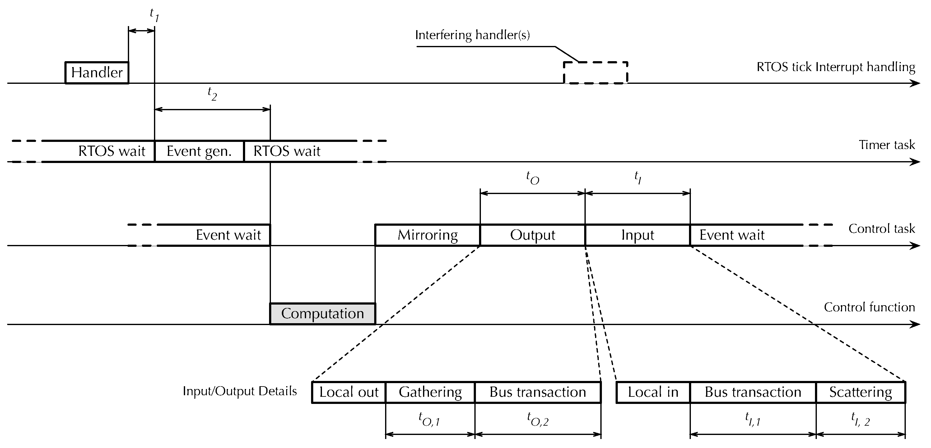
Figure 12 illustrates which time measurements have been performed by means of a timing diagram. The diagram is organized vertically along the four operational layers that together implement synchronization and cyclic execution within
RtFw.
The topmost layer is the
FreeRTOS tick interrupt handler, executed every 1 ms. Besides using the handler to perform internal timekeeping activites—for instance, delayed task activation—
FreeRTOS supports a timer
hook function and invokes it from the handler on every tick. This provides a convenient timestamping point located very early in the
RtFw cyclic synchronization chain. In the figure,
represents the time needed to synchronize the first layer with the second. More specifically, it is the delay between the end of the hook and timer task activation, defined as the conclusion of its passive wait operation, implemented by means of the
vTaskDelayUntil FreeRTOS primitive, as described in
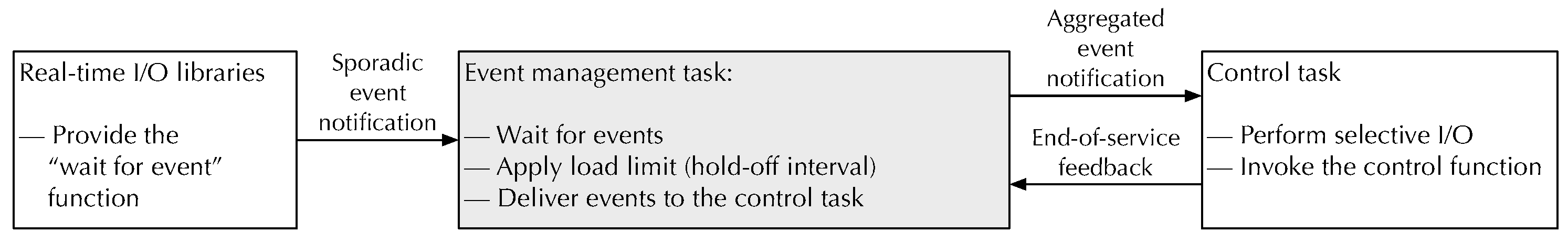
Section 4.1. In turn, the
timer task in the second layer triggers the activation of the
control task in the third, passing through the event system also discussed in
Section 4.1. Event propagation within
RtFw takes an amount of time denoted as
.
The control task performs most of the cyclic activities of
RtFw, including the activation of the fourth and last layer, the user-written
control function. Here, measurements have been focused solely on I/O operations, because the control function content is going to vary depending on user-level application requirements and measuring its execution time in a specific case would have had little practical significance. Moreover, as explained in
Section 6, mirroring between PI and shared memory variables consists of a memory-to-memory copy involving data items of small size, which is negligible unless the number of variables being copied is atypically large.
Therefore, the measurements in the third layer are the total output time and the total input time . Each of them consists of local and Modbus communication. Then, Modbus communication time was further split up to evaluate the data gathering/scattering times, called and , respectively, as well as the output and input bus transaction times and . Local I/O time was not singled out because it was found to be negligible with respect to Modbus communication time.
Data gathering and scattering are an essential part of the Modbus I/O process because, for better efficiency,
RtFw carries out bus transactions in aggregated form whenever possible. In other words, PI variables that are either all inputs or all outputs and are mapped to a contiguous range of addresses on the same board are transferred in a single bus transaction. Aggregation decisions are taken just once before cyclic activities begin, and hence, do not contribute to
RtFw overhead within the control cycle itself. On every cycle, however, it is still necessary to gather the PI variables to be aggregated and copy their values into the contiguous data buffer to be used for the output transaction. Symmetrically, after an input transaction has taken place, data retrieved from the remote I/O board must be copied into the corresponding PI variables, which are scattered through memory.
Table 1 summarizes experimental results. For each delay, the mean value (
), standard deviation (
), and minimum and maximum value (Min and Max) are shown.
The main conclusion that can be drawn from those results is that the overhead is dominated by Modbus CAN I/O time rather than
RtFw. In turn, Modbus CAN I/O time depends for the most part on the CAN bus bit rate [
41], which has already been set to the maximum in the experiments. More specifically, the total
RtFw overhead
for inter-layer synchronization and I/O setup can be written as
and its average in the experiments was
. In contrast, the average Modbus CAN I/O time
, expressed by
was
. Therefore,
represents less than 6% of the total overhead even when it is maximized by reducing the I/O time to the minimum (1 input and 1 output 16-bit I/O point). Another important aspect is the extremely low standard deviation of
, which stayed consistently below what could be measured during the experiment. This confirms the suitability of
RtFw for accurate real-time embedded applications, despite the higher level of abstraction it introduces in programming them.
The second part of the evaluation focused on the behavior of
and
as a function of the number of 16-bit I/O points. The results are shown in
Table 2. The maximum number of I/O points considered in the experiments was 8 because Modbus I/O boards typically have between 2 and 8 analog inputs or outputs, each accessed by means of a 16-bit register [
55]. The number of digital I/Os may be larger, but up to 16 of them are normally packed into the same I/O register. Besides confirming the expected direct dependency of
and
from the number of I/O points, the additional measurements confirm that the combined input and output standard deviation does not increase significantly and stays below 6 µs in all considered scenarios. The extra jitter incurred by
when the number of I/O points exceeds two can be attributed to additional interference from the 1 ms RTOS tick handler that overlaps with the I phase of the control cycle in those cases, as also depicted in
Figure 12.
8.2. Event-Driven Reactivity
The reaction time of
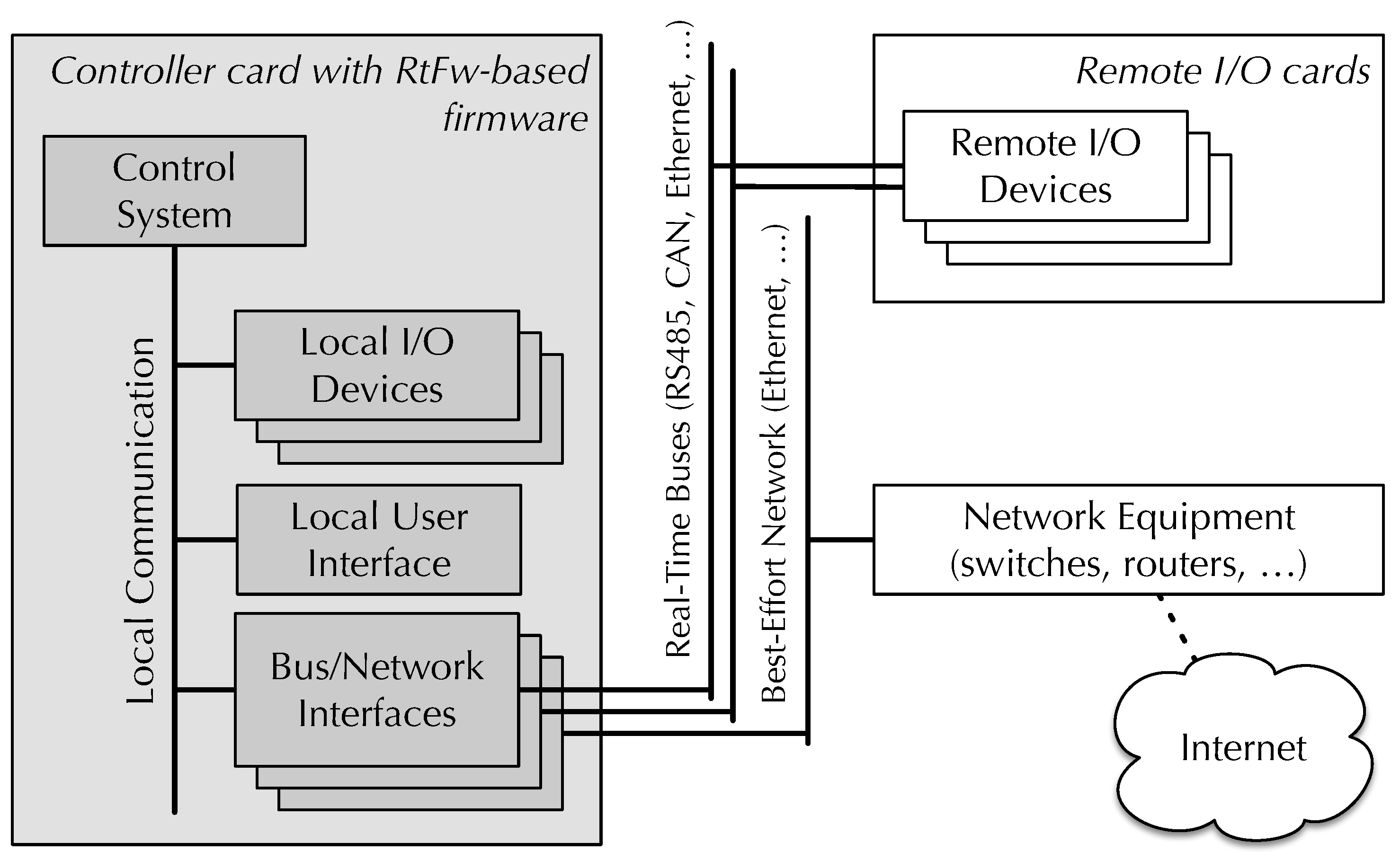
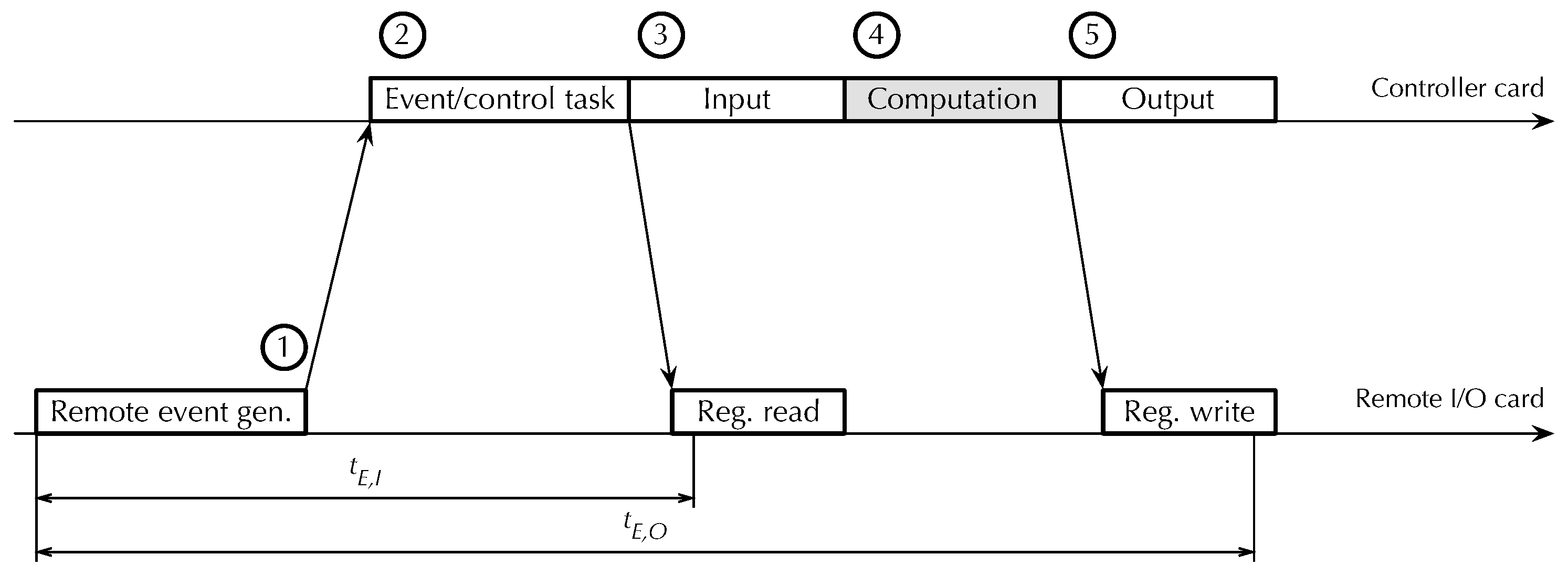
RtFw to an external event originating from a remote I/O card, which is crucial for event-driven programming performance, has been evaluated in the scenario shown in
Figure 13. It consists of the following steps:
A remote Modbus I/O card generates an event and sends an asynchronous event notification message ➀ to the controller card via a real-time bus.
The controller card firmware reacts by activating the event handling task and then the control task ➁.
The control task performs a selective input operation ➂, activates the control function to handle the event ➃, and performs a selective output operation ➄.
Figure 13.
Framework timing diagram, event-driven execution. Bus traffic not shown for clarity.
Figure 13.
Framework timing diagram, event-driven execution. Bus traffic not shown for clarity.
The input and output operations that the controller card performs are seen by remote I/O cards as a sequence of Modbus register read and write operations, respectively. For writes, the timestamping point has been placed after the remote I/O card received the Modbus request from the controller card and the data to be written, but before it sent the corresponding acknowledgment. For reads, the timestamping point has been placed as soon as the remote I/O card becomes aware of the request. Therefore, represents the total reaction time of the controller card to a remote event, measured from event generation to the time at which the reaction becomes externally observable as a change of state of some of its outputs. Time , instead, is the earliest point in time when the remote I/O card that generated the event becomes aware that event handling has started.
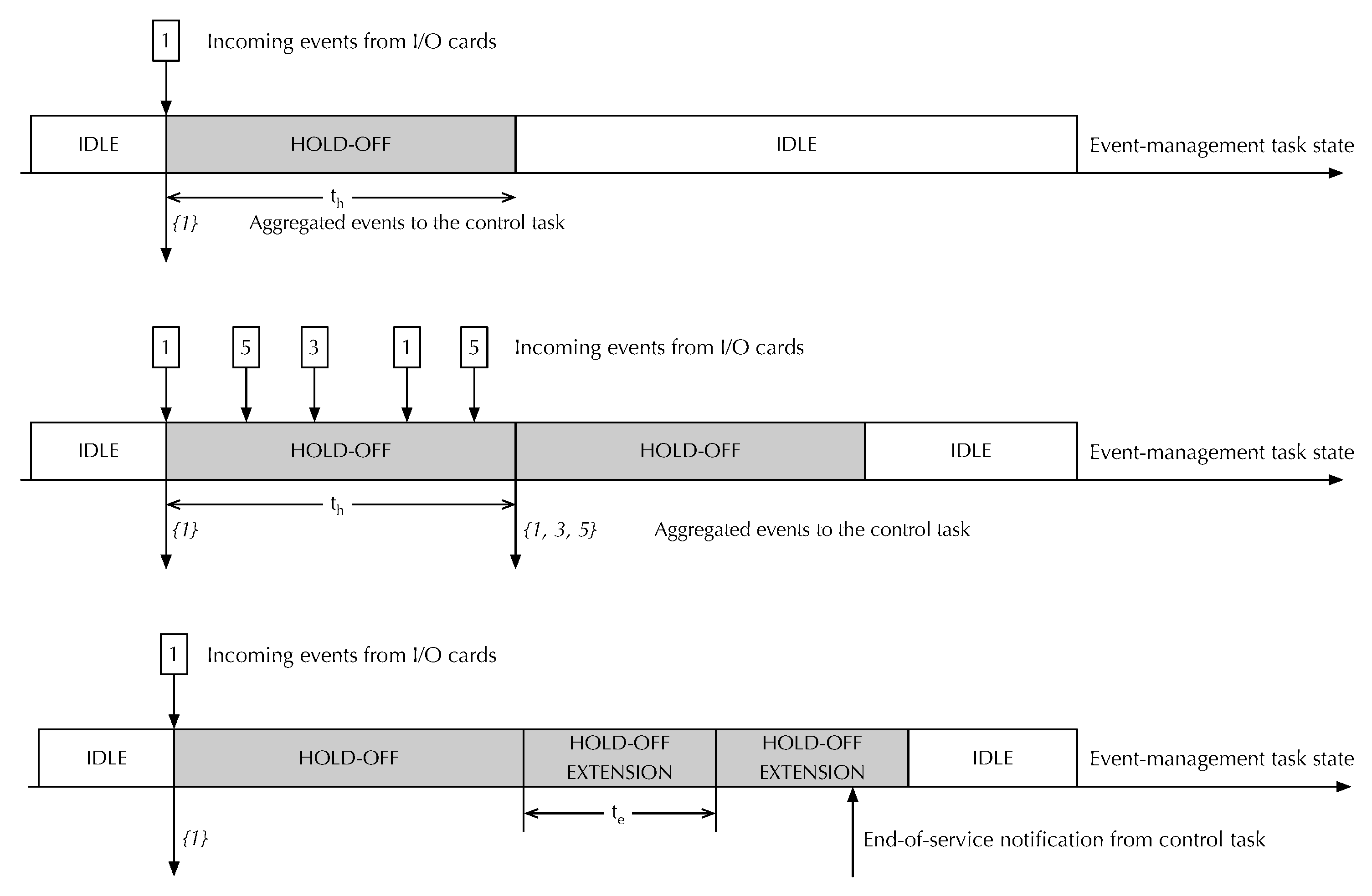
Table 3 lists experimental results, as before, as a function of the number of 16-bit I/O points. The interval between consecutive remote event generations was set to a value greater than
for the experiment to avoid triggering the activation of event gathering and hold-off interval extension. Moreover, care has been taken to avoid any interference from time-driven activities while handling an event. As in the previous set of experiments, the control function content was kept to a minimum.
Barring measurement noise, remained constant as the number of I/O points varied. This was to be expected because a Modbus register read request has a fixed length, regardless of the number of registers to be read. Instead, depends on the number of I/O points because their values are transferred together with the Modbus register write request. What is more important though, is that remained below 1.3 ms, even in the worst case, with a standard deviation below 4 µs, thus confirming that RtFw is able to respond to external events timely and consistently.
8.3. Memory Footprint
Table 4 contains information about the
RtFw memory footprint, broken down into categories as follows:
The base modules of the framework, comprising its real-time tasks (
Section 4.1) and configuration data structures (
Section 6).
The Modbus and local real-time I/O modules.
The shared memory management modules, including mirroring.
Additional utilities, mainly consisting of functions to dump framework data structures in a human-readable format as a high-level debugging aid.
The main program of the application firmware, which initializes RtFw and implements a minimal control function.
Table 4.
Memory footprint divided by category.
Table 4.
Memory footprint divided by category.
| Category | Text + RO Data (B) | RW Data (B) | BSS (B) |
|---|
| RtFw base | 5257 | 0 | 136 |
| Event management | 1536 | 0 | 0 |
| I/O modules | 5384 | 0 | 0 |
| Proxies | 3112 | 0 | 40 |
| Shared memory management | 868 | 0 | 56 |
| Utilities | 6879 | 0 | 0 |
| Main program | 1481 | 0 | 2272 |
| Total | 24,517 | 0 | 2504 |
The footprint measurement confirmed that RtFw can profitably be used even on extremely low-cost microcontrollers with limited memory resources. More specifically, its memory requirement amounts to less than 5% of the total Flash memory available on the LPC1768 (512 KB) and less than of 4% of its RAM (64 KB).
Besides
RtFw, the application firmware must typically be linked against several additional libraries, for instance, the Modbus master and slave protocol libraries, the lwIP library, the
FreeRTOS library, and the C runtime libraries. Their memory footprint has not been reported because they would still be needed even if
RtFw were not used at all. Moreover, quantifying the exact memory footprint of these libraries would have been hard, because it highly depends on application-level code requirements and how the libraries themselves have been optimized. For instance, the C library heap can be reduced in size or eliminated completely if the application does not require dynamic memory allocation. Similarly, the C library
newlib [
56] offers specific configuration options for systems with limited RAM memory [
57].
8.4. Comparison with Other Frameworks
The framework was compared with two other approaches among the ones discussed in
Section 2. Namely, CPAL was selected among higher-level, MBD frameworks because it has successfully been used for practical cyber-physical and embedded applications. Moreover, it supports both interpreted and compiled execution, which provided further insights for the comparison. Arduino was chosen as a representative of lower-level, C++-based frameworks due to its popularity and availability on a variety of hardware platforms. In both cases, the hardware platform used for the comparison was the one closest to the
RtFw testbed described in
Section 8, chosen among the platforms for which a publicly available port was available.
Table 5 summarizes those platforms and their main characteristics. To bring them as close as possible, all cores but one have been disabled on multi-core processors, and the BCM2837 has been forced to operate at its minimum clock speed.
The comparison was carried out according to the following metrics: (a) minimum sustainable time-driven cycle time without incurring systematic timing errors; (b) total (code+data+BSS) footprint of the framework, as determined by the
size tool, including dynamically linked libraries and excluding the operating system, unless bundled with the application; (c) level of programming abstraction. They were selected as a trade-off between the lack of access to the source code of CPAL and Arduino, which prevented its instrumentation and their significance. In particular, metric (a) is a black-box method to evaluate the total overhead of a framework. Metric (b) is undoubtedly less precise than the memory footprint evaluation of
Section 8.3 but can easily be extracted from the executable image and still provides valuable information. Metric (c) directly affects programmers’ productivity and learning curve. The elementary application used for the experiment was the same for all frameworks. It reads two 16-bit input variables from a remote I/O card using the Modbus-CAN protocol, checks for I/O errors, calculates their minimum and maximum if possible, and writes the results into two 16-bit remote output variables. For a fair comparison, the same communication libraries were used with all frameworks, leading to the I/O timings listed in the second row of both sub-tables of
Table 2. The minimum cycle time was measured by starting at 8 ms, proceeding by bisection towards 1 ms, and stopping when a systematic timing error was detected. Raw experimental results are shown in
Table 6, while
Table 7 summarizes the outcome of the comparison in a semi-quantitative way, where frameworks are classified as “+” (advantageous), “∘” (neutral), or “−” (disadvantageous) with respect to the others based on the results.
All frameworks but interpreted CPAL were able to achieve a cycle time of 1 ms and were classified as “+” in the corresponding column of
Table 7. Interpreted CPAL was classified as “−” instead.
RtFw had the lowest footprint and was therefore classified as “+” in this category. The footprint of Arduino was about twice as high as
RtFw, which led to its “∘” classification. Both variants of CPAL were classified as “−” because their footprint was 5–10 times as high as
RtFw. Moreover, both interpreted and compiled CPAL code require an underlying Linux operating system to run, which was not taken into account in
Table 6 and further increases the total memory footprint. On the contrary, the application images produced by Arduino and
RtFw are completely self-contained and run on bare metal. For what concerns the level of abstraction, due to the arguments presented in
Section 2, both variants of CPAL were classified as “+” (since they belong to the MBD class), and Arduino was classified as “−” (because it is based on plain C++ programming).
RtFw was classified as “∘” (because it combines features of both classes).


