Article

A Low-Complexity Solution for Optimizing Binary Intelligent Reflecting Surfaces towards Wireless Communication

by
Santosh A. Janawade 
1,
Prabu Krishnan 
1,*,
Krishnamoorthy Kandasamy 
1,
Shashank S. Holla 
1,
Karthik Rao 
1 and
Aditya Chandrasekar 
2
1
Department of Electronics and Communication Engineering, National Institute of Technology Karnataka, Mangalore 575025, India
2
Department of Electrical and Electronics Engineering, National Institute of Technology Karnataka, Mangalore 575025, India
*
Author to whom correspondence should be addressed.
Future Internet 2024, 16(8), 272; https://doi.org/10.3390/fi16080272
Submission received: 2 June 2024 / Revised: 22 July 2024 / Accepted: 24 July 2024 / Published: 30 July 2024
(This article belongs to the Section Smart System Infrastructure and Applications)

Abstract

:
Intelligent Reflecting Surfaces (IRSs) enable us to have a reconfigurable reflecting surface that can efficiently deflect the transmitted signal toward the receiver. The initial step in the IRS usually involves estimating the channel between a fixed transmitter and a stationary receiver. After estimating the channel, the problem of finding the most optimal IRS configuration is non-convex, and involves a huge search in the solution space. In this work, we propose a novel and customized technique which efficiently estimates the channel and configures the IRS with fixed transmit power, restricting the IRS coefficients to  { 1 , 1 } . The results from our approach are numerically compared with existing optimization techniques.The key features of the linear system model under consideration include a Reconfigurable Intelligent Surface (RIS) setup consisting of 4096 RIS elements arranged in a 64 × 64 element array; the distance from RIS to the access point measures 107 m. NLOS users are located around 40 m away from the RIS element and 100 m from the access point. The estimated variance of noise  N C  is 3.1614  ×   10 20 . The proposed algorithm provides an overall data rate of 126.89 (MBits/s) for Line of Sight and 66.093 (MBits/s) for Non Line of Sight (NLOS) wireless communication.

1. Introduction

As mobile communication evolves, every new generation introduces new features, especially for the higher transmission rate. The demands for 5G are still evolving, and complete 5G infrastructure is getting rolled out. The researchers are working on 6G, anticipating demands based on future needs [1]. An Intelligent Reflecting Surface (IRS) is an umbrella term that appeared recently in the electromagnetic [2,3] and wireless domains [4]. Reflecting surfaces, also known as intelligent or reconfigurable surfaces, can play a significant role in 5G and potential future 6G communication networks [5,6]. These reflecting surfaces are periodic and designed to manipulate the transmission of electromagnetic waves to enhance wireless communication in various ways. An IRS is a two-dimensional structural array of metamaterial cells and, by tuning impedance variations over the cluster of the unit cell surface, the interaction with incident electromagnetic waves can be controlled [7]. For the enhancement of the wireless communication systems of the 5G and especially the 6G networks, an IRS plays an significant role. In the evolution of cellular technology up until 5G, the channel was deemed to be uncontrollable, and the focus was mainly on spectral efficiency and antennas. But recently, the IRS has attracted emerging technological attention, and is regarded as an innovative tech infrastructure for the beyond fifth-generation (B5G) communication systems because of its potential to achieve significant improvement in communication coverage, latency, throughput, device density, and energy efficiency.The work in [8] lists the five emerging antenna array research directions. The work illustrates the possible solutions to achieve the high speed and coverage problems. The IRS phase shift model, explained in [9], helps in the beamforming of the incident EM waveform to the receiver. An IRS comprises low-cost periodic reflecting elements mounted on a planar surface. These metasurfaces can be used in 6G communication systems to direct incident wireless signals from a transmitter towards a receiver. It can achieve 3-D passive beamforming via joint signal reflection [10].
The studies in [11] propose a low-complexity framework for channel estimation and passive beamforming in RIS-assisted Multiple-Input and Multiple-Output (MIMO) systems. The approach involves partitioning the channel training phase and pre-designing RIS reflection coefficients to estimate the effective superposed channel, thus reducing complexity. The framework optimizes RIS reflection by selecting from a pre-designed training set to maximize achievable rates. Novel methods for generating RIS reflection coefficient training sets are introduced, showing significant performance benefits over traditional methods, especially in fast-changing channels with limited coherence time. The results demonstrate the proposed framework’s competitive advantage in terms of complexity, pilot overhead, and signaling requirements. The work in [12] explores codebook-based solutions for a RIS in wireless communication, focusing on channel estimation and passive beamforming challenges. It introduces a framework that uses a pre-designed codebook for RIS reflection patterns, reducing pilot signaling overhead and complexity. This method enhances energy efficiency, scalability, and system performance, providing a practical approach for RIS-assisted communication systems without relying on complex model assumptions.
The studies in [13] introduced a novel approach leveraging stacked intelligent metasurfaces (SIMs) for advanced signal processing in the electromagnetic wave domain. This SIM-based system aims to enhance holographic MIMO (HMIMO) communications by integrating multiple metasurface layers at both the transmitter and receiver ends, effectively minimizing the need for numerous RF chains. The proposed system optimizes the phase shifts of the metasurface layers to create interference-free parallel subchannels, significantly improving channel capacity and performance. The authors also present a gradient descent algorithm to solve the non-convex optimization problem and provide theoretical analysis and simulation results demonstrating substantial performance gains over traditional MIMO and RIS-aided systems. The work in [14], which has a SIM-aided MIMO transceiver design, suggests significant potential for the future of wireless networks. By utilizing programmable metasurfaces composed of multiple layers of passive meta-atoms, this technology can directly achieve sophisticated signal processing tasks, such as MIMO precoding and interference mitigation through wave propagation. This method notably decreases RF energy use and simplifies hardware. The SIM architecture offers potential advantages in computational efficiency, ultrafast processing speeds, and simplified hardware, positioning it as a promising technology for next-generation wireless networks.
The study carried out by Xu et al. in [15] introduces a novel minimum mean squared error (MMSE)-based interpolation method to improve channel estimation in high-mobility RIS-assisted wireless systems, addressing the issues posed by high Doppler frequencies. It models the system with both LOS and NLOS paths and evaluates both direct and RIS-reflected links. Simulations show that this approach significantly enhances power efficiency for high-speed users at the cell edge, outperforming existing techniques that assume block fading and struggle under high Doppler conditions. The work in [16] focuses on enhancing high-mobility wireless systems by utilizing RIS with OFDM in doubly selective Ricean channels. It proposes sophisticated MMSE-based channel estimation techniques in frequency and time domains, addressing interference and improving signal detection. The study demonstrates that RIS can significantly boost performance, especially in lower 5G frequency bands, despite challenges like increased Doppler frequency and path loss at higher frequencies.
The authors of [17] present a scalable method for enhancing RIS-OFDM systems through efficient channel estimation and reflection optimization. It uses pre-generated RIS reflection coefficients to estimate channels and optimize power allocation, reducing training overhead and complexity. The approach adapts to channel coherence times, improving system performance and achievable rates compared to traditional methods. The study conducted by [18] presents a scalable method for enhancing RIS-OFDM systems through efficient channel estimation and reflection optimization. It uses pre-generated RIS reflection coefficients to estimate channels and optimize power allocation, reducing training overhead and complexity. The approach adapts to channel coherence times, improving system performance and achievable rates compared to traditional methods.
We consider a setup in which an IRS structure is mounted in Line of Sight (LOS) with the base station (BS). The BS-User channel and the channel between the IRS and the user can be either LOS or Non-Line of Sight (NLOS). In Figure 1, the IRS consists of a set of small passive elements that can take any value within the range  [ 1 , 1 ] . In our research paper, we have considered that RIS element sizes are typically sub-wavelength-sized (e.g., a square patch of size  λ / 5 × λ / 5 ) to behave as scatterers without a strong intrinsic directivity [19].
The Table 1 summarizes the pros and cons of state-of-the-art research on IRS-aided wireless communication systems, including some of the most cited papers and recent publications.
For the channel estimation and configuration search, the key challenges and constraints of the work are as follows: For estimating the channel, the first challenge is that most details of the channel properties, such as the physical model of the IRS and surrounding environment, are unknown. Secondly, we must decide whether to estimate the channel separately for LOS or NLOS users. After the channel is estimated, mapping IRS configurations to the data rate is possible. The combination of all possibilities for configuration search is  2 4096 , or effectively infinite. So, the challenge is that the IRS configuration is in discrete space; therefore, defining optimization objectives, loss function, and the gradient is not straightforward. Furthermore, if we somehow map the IRS to continuous space, the complexity of the mapping function results in the non-convex optimization problem. So, our algorithms must effectively address all these constraints in real-world wireless communication applications. However, in practical terms, obtaining passive elements that can be tuned to a continuous range of values is not feasible [20]; hence, to cater to the needs of simple hardware, we restrict the value that an IRS element can take to either  1  or  + 1 . The IRS is a  64 × 64  surface with 4096 tunable elements. Hence, the total number of possible configurations is  2 4096 , making it impractical to check each configuration.
Table 1. Pros and cons of state-of-the-art research on IRS-aided wireless communication systems.
Sl. No.Paper TitleProsConsDiscussion
1.Secrecy Rate Maximization for IRS-Assisted Multi-Antenna Communications (2019) [21]
-
Significant secrecy rate improvement by optimizing active transmit and passive reflect beamforming.
-
Enhanced power efficiency and interference suppression
-
Complexity in joint beamforming design. - Path loss considerations for multi-reflection scenarios
This paper demonstrates that IRS can significantly boost secrecy rates by careful phase shift optimization, addressing security in wireless networks.
2.Secure Wireless Communication via IRS (2019) [22]
-
Increased secrecy rates with more IRS elements.
-
Constructive and destructive signal alignment for user and eavesdropper.
-
High correlation between channels can limit improvements.
-
Complex optimization for maximal secrecy rates.
This study highlights the potential of IRS in secure communication by optimizing reflect beamforming to enhance desired signals and suppress eavesdropping.
3.Configuring an IRS for Wireless Communications (2021) [23]
-
Demonstrated practical implementation in competitions.
-
Effective in real-world settings with configurable parameters
-
Potential high implementation cost.
-
Limited by the accuracy of CSI acquisition and configuration.
This paper showcases the practical applications of IRS, underlining its feasibility and effectiveness in enhancing wireless communication systems in controlled environments.
4.Intelligent Reflecting Surface Enhanced Wireless Network: Joint Active and Passive Beamforming Design(2018) [24]
-
Enhanced signal propagation through smart reconfiguration.
-
Low-cost passive elements.
-
Significant performance gains with joint beamforming.
-
High computational complexity for optimization.
-
Excessive channel estimation overheads.
This paper proposes a centralized algorithm using semidefinite relaxation (SDR) for the joint optimization of transmit and reflect beamforming, and a distributed algorithm to reduce overheads. The IRS significantly improves link quality and coverage.
5.SChannel Estimation for Reconfigurable Intelligent Surface Assisted High-Mobility Wireless Systems (2022) [15]
-
Effective in high-mobility scenarios.
-
Improved channel estimation accuracy.
-
Complex algorithm implementation.
-
High computational resource requirements.
This research addresses the challenges of channel estimation in high-mobility environments, proposing a novel algorithm that enhances estimation accuracy by leveraging the IRS’s ability to adjust phase shifts dynamically.
6.Stacked Intelligent Metasurface-Aided MIMO Transceiver Design (2024) [14]
-
Ultrafast computational speed due to wave-based processing.
-
Simplified hardware with reduced energy consumption
-
Initial exploration phase with numerous open challenges.
-
Need for efficient inter-layer transmission models and CSI acquisition methods.
This recent work proposes a novel SIM concept for MIMO systems, offering significant improvements in processing speed and energy efficiency but requiring further research to address existing challenges.
The implementation methodology for the IRS involves two steps: channel estimation and maximizing the rate function. We use the dataset’s pilot configurations to estimate the controllable and uncontrollable channels. Secondly, the linear model is used to characterize the system. Then, we estimate the channel. Searching for the best configuration for a high-data-rate genetic algorithm with a gradient descent algorithm could also be used sequentially to optimize each user’s IRS configuration. The proposed work and its two algorithms for the best IRS configuration for higher data rates are explained in Section 3 and Section 4 in detail. Genetic algorithms (GAs) are employed in RIS-assisted OFDM systems to optimize the configuration of reflection coefficients. Each potential solution, or chromosome, represents a set of RIS reflection coefficients. The process starts with initializing a diverse population of these chromosomes. Each chromosome’s effectiveness is then evaluated using a fitness function that measures key performance metrics, such as signal-to-noise ratio (SNR) or throughput. The best-performing chromosomes are selected through a roulette wheel or tournament selection, ensuring that the most promising solutions are carried forward. Following selection, crossover and mutation operations are applied to introduce variation and create new offspring chromosomes. Crossover combines parts of two chromosomes, while mutation introduces random changes, maintaining genetic diversity and preventing premature convergence on suboptimal solutions. This iterative process continues until the fitness function stabilizes, indicating an optimal or near-optimal set of RIS reflection coefficients.
The problem is split into two sub-problems: channel estimation and IRS configuration. Optimizing the IRS configuration to obtain a better data rate is a non-convex problem. From prior research, it is observed that computationally complex algorithms along the lines of Machine learning [25], Lagrangian Dual Transform [26], and semidefinite relaxation [27] are used to tackle this problem. Whereas in practice, the time taken for optimizing the IRS configuration is as important as optimizing it. Keeping in mind the constraints on time and processor capacity, we propose a low-complexity solution that uses the inherent structure in the data and a greedy heuristic to obtain an optimized configuration that works for both LOS and NLOS users [26,28]. The terms used in the system modelling are listed in Table 2.
This article delves into configuring an IRS for wireless communications, focusing on developing signal-processing algorithms tailored to optimize IRS settings based on user locations. Key contributions include innovative algorithms for estimating propagation channels and optimizing data rates. This work addresses challenges such as frequency-selective fading, discrete phase shifts, hardware imperfections, and limited measurement data, emphasizing the novel algorithms and methodologies created to overcome these obstacles. The research provides significant insights into critical aspects of wireless communication, including channel modeling, statistical estimation, and optimization techniques. Utilizing MATLAB for the practical setup and synthetic data generation offered a realistic environment for testing these algorithms.
The rest of this paper is organized as Section 2, the system model, followed by Section 3 with its channel estimation. At the same time, its subsection gives the gist for the noise estimation, followed by a subsection on finding parameters. Section 4 elaborates on rate optimization, where the algorithms developed are explained in its subsections: initialization and further optimization. Section 5 gives the elaborated results and outcomes of the algorithm and compares the results with the results available in the literature. Section 6, finally, concludes the entire work.

2. System Model

We consider transmission of electromagnetic (EM) signal over the communication channel using OFDM technique. The system model under consideration is a linear cascaded model. The entire bandwidth of the system is conventionally split into K orthogonal subcarriers. Let  x ( t )  denote the transmitted EM signal, and  z ( t )  be the received EM signal. We consider the impulse responses of four parameters in modeling the end-to-end channel- h d ( t ) a ( t ) b ( t ) , and  θ . Suppose there are  L 1  propagating paths from the BS to the nth IRS element, then  a ( t )  can be modeled as [29]:
a n ( t ) = l = 1 L 1 α n l e j 2 π f c t δ ( t τ n l )
where  α n l  [0,1] is the path propagation loss,  τ n l 0 represents the delay of the lth path and  δ ( t )  represents the Dirac delta function. Likewise,  b ( t )  can be modeled as [29]:
b n ( t ) = l = 1 L 2 β n l e j 2 π f c t δ ( t τ n l )
We place a constraint on the values that the IRS elements can take; they can only take values from the set  { 1 , 1 } . The superimposed channel response in the time domain can be given by [30]:
h θ = h d + ( a b ) θ
here * represents the convolution operation. The received signal is then given by:
z ( t ) = h d ( t ) + ( h θ x ) ( t ) + ω ( t )
The discrete-time form of Equation (4) can be represented as follows:
z [ k ] = m = x [ m ] h θ [ k m ] + ω [ k ]
where  h θ [ 0 ] , , h θ [ M 1 ]  represents the non-zero components of the finite impulse response (FIR) filter with M ≥ 1 terms. Taking the Fourier Transform of (5) and with  F  representing the Fourier Transform, we obtain:
F ( z ) = ( H d + V θ ) F ( x ) + N C

3. Channel Estimation

3.1. Noise Estimation

The first step in estimating the channel parameters  H d  and  V  is estimating the noise present in the channel. This is accomplished by sending the same pilot transmission signal twice, keeping the IRS configuration constant. Since we have assumed that the BS and the user is static, we can also assume that the parameters  H d  and  V  remain the same. Writing the two equations in the form of (6), we obtain:
F ( z 1 ) = H d F ( x ) + N C 1
F ( z 2 ) = H d F ( x ) + N C 2
Determining the difference between Equations (7) and (8), we see that all the terms on the RHS get cancelled, except for the noise term. We can measure this by finding the difference between the left hand side (LHS) term. Repeating this for many different IRS configurations with the same transmit pilot signal and finding the variance of all such values, we find that the new random variable will have twice the variance of the original noise random variable. We already know that the mean of a CSGN random variable is 0. Thus, with this knowledge of the mean and variance, we can estimate the noise in the future stages. The OFDM transmission employs a cyclic prefix of length  M 1  and generates  K > M  subcarriers. Therefore, a block of  K + M 1  time-domain signals is sent to form one OFDM block with K parallel subcarriers. In this context, M equals 20, K equals 500 subcarriers, there are 50 users, and N equals 4096 IRS cells. The received signal matrix has the dimensions  K × 4 N  =  500 ×  16,384, while the transmitted signal matrix has the dimensions  K × 1  =  500 × 1 . Equations (7) and (8) are of the order  K × 4 N  =  500 ×  16,384.

3.2. Finding  H d  and  V

After estimating the channel noise, we can estimate the channel parameters  H d  and  V . Switching off the IRS, from (6), we obtain:
F ( z ) = H d F ( x ) + N C
H d = ( F ( z ) N C ) F ( x ) 1
With the knowledge of  H d , we can proceed to estimating  V . Let  ϕ  be the matrix  [ θ 1 θ 2 θ 4096 ] Z  be the matrix  [ F ( z ) 1 F ( z ) 2 F ( z ) 4096 ]  and  N  be the matrix  [ N C 1 N C 2 N C 4096 ] . From (6), we obtain:
Z = ( H d + V ϕ ) F ( x ) + N
H d + V ϕ = ( Z N ) F ( x ) 1 = Λ
V = ( Λ H d ) ϕ 1

4. Rate Optimization

For a given IRS configuration  θ , the achievable rate [30,31,32] is as follows:
R = B K + M 1 i = 0 K 1 log 2 1 + P | H d i + V i θ | 2 B N 0
where  H d i  is the ith row of  H d V i  is the ith row of  V , B represents the bandwidth (symbol rate), P is the signal power, and  N 0  represents the noise power spectral density. Maximizing the rate equation will lead to overall enhancement in the IRS system. There are two stages in maximizing the rate equation.

4.1. Initialization

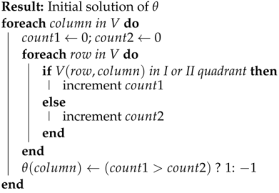
The phases of 500 channel elements of V for every column are examined and a suitable value of  θ  element corresponding to that column is chosen so that, for most channel elements,  V × θ  lies in the I or II quadrant. If this happens, there will be constructive interference, which potentially leads to beamforming among the channel elements leading to higher rates. The initialization algorithm is illustrated in Algorithm 1.
The initialization algorithm gives good rates for LOS users but it does not perform well for NLOS users. This is because most of the channel elements are concentrated in 2 quadrants for LOS users, but for NLOS users, these channel elements are distributed equally across all quadrants. Getting all the channel elements onto a single half of the Cartesian plane is hard, and hence, we use another algorithm on top of this to get better rates for the NLOS users.
Algorithm 1: Initialization algorithm
Futureinternet 16 00272 i001

4.2. Further Optimization

The  θ  vector obtained in the previous step is the input in this stage. The rows of  V  are arranged in descending order, based on the sum of the square of the magnitude of the elements. For every row of  V  which corresponds to a particular subcarrier, a temporary IRS configuration  θ 2  is calculated using the principles of Algorithm 1. A greedy solution is then used to improve the rate further. The number of steps in the greedy solution is kept high in the initial rows (which corresponds to higher magnitude) and is gradually decreased to cater to the time complexity. This approach is illustrated in Algorithm 2.
Algorithm 2: Further optimization
Futureinternet 16 00272 i002

5. Results

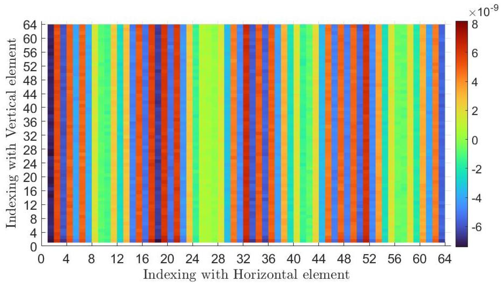
This section lists simulation results to numerically validate our algorithm and compare the results obtained using other well-established algorithms with the same conditions. We carried out the simulation using MATLAB to create a complex indoor environment with frequency-selective fading.The datasets are provided by Emil Björnson [23]. It captures various practical aspects of wave propagation, such as frequency-selective fading, orthogonal frequency-division multiplexing signaling, and mutual coupling between closely spaced elements. Our setup involved a wireless base station serving multiple users, with an IRS containing 4096 controllable elements placed on a wall to improve signal strength. These IRS elements had two tunable impedance states to reflect radio waves. We aimed to optimize data rates for 50 user locations by identifying the best IRS configurations. The dataset provided noisy received signals corresponding to various pilot signals and IRS configurations. We processed these signals to find the optimal setup, and due to the impracticality of exhaustively searching all possible configurations ( 2 4096 ), we employed efficient selection algorithms. We faced challenges in channel estimation, with more unknowns than observations, which required structured dimension reduction techniques. We used two evolutionary algorithms, and also compared these with algorithms such as genetic algorithms, to navigate the ample configuration space effectively. Our work demonstrated the necessity of interdisciplinary expertise in electromagnetics, communication, and signal processing to develop practical IRS configurations. As mentioned in the previous section, we aimed to increase the overall rate across all subcarriers (14) for both LOS and NLOS users.The  64 × 64  spatial reflecting surface, in order to beam form the signal to particular user, has an horizontal and vertical indexed arrangement, as retrieved from dataset1, and its nature is shown in Figure 2.
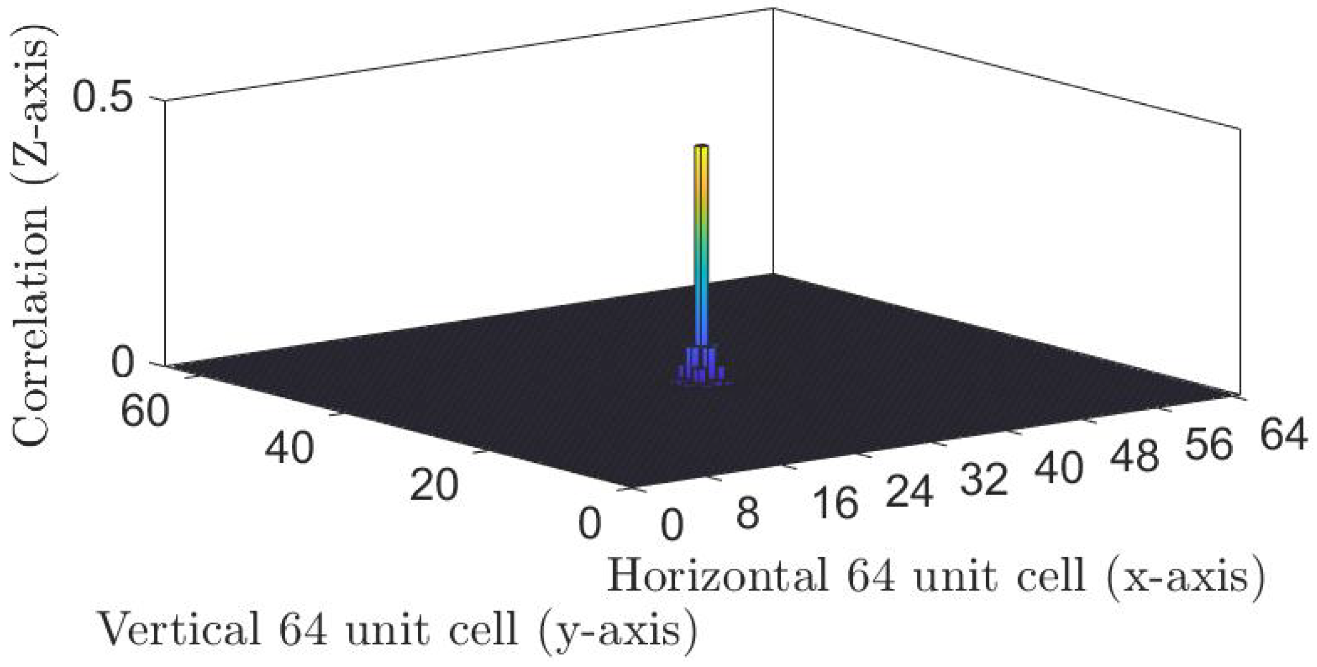
The columns show that the turning of the diodes On or Off is same throughout the vertical direction and minimally varies as we progress in the horizontal direction of the cell arrangement.Hence, the impedance applied in vertical direction arrangement of unit cell is supposed to be constant for achieving the proper beamforming of the signal and achieving a high data rate. The mutual coupling induced at the center of the  64 × 64  cell’s IRS pattern is measured, which is plotted in Figure 3. Thus, a tightly packed element’s cell results in significant coupling losses, and the cell under observation is more impacted by neighboring cells. The coupling capacitance [33] was measured with the help of Equation (15).
C n = i = 1 N C ˜ i , θ 100 d n , i / λ j = 1 N 100 d n , j / λ
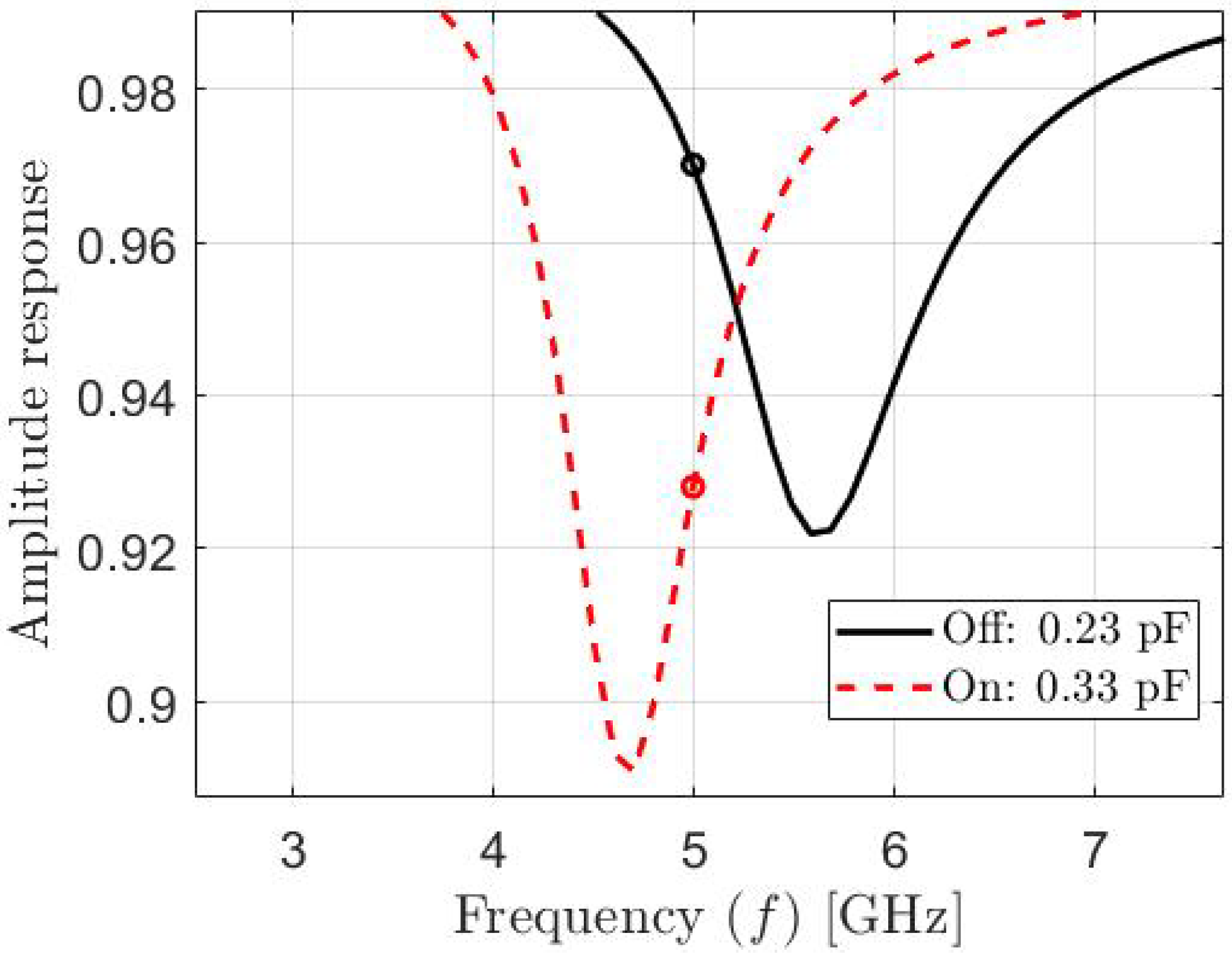
where  d n , i = u n u i  is the distance measured between nth cell and ith cell. Figure 4 and Figure 5. represent the element unit cell’s phase plot and amplitude response plot. The waveform clearly shows that at 5 GHz frequency, the phase difference of 180° is applied at the incident waveform by the unit cell, which will help the incident EM wave to reflect in the desired receiver direction. The amplitude loss of  3 %  is observed in the diode Off state and by  7 %  in the On state.
The pathloss [19 β I R S  is measured by Equation (16) and is plotted in Figure 6 for different arrangements of IRS elements. In pathloss calculations, the incident angle  Θ i = 30 ° , the desired angle  Θ r = 60 ° , where the antenna gains are maintained at Gt = Gr = 5 dB, the distance di = 100 m, and the receivers are at 40 m.
β IRS r , d i , θ r = G t G r ( 4 π ) 2 a b d i r 2 cos 2 θ i
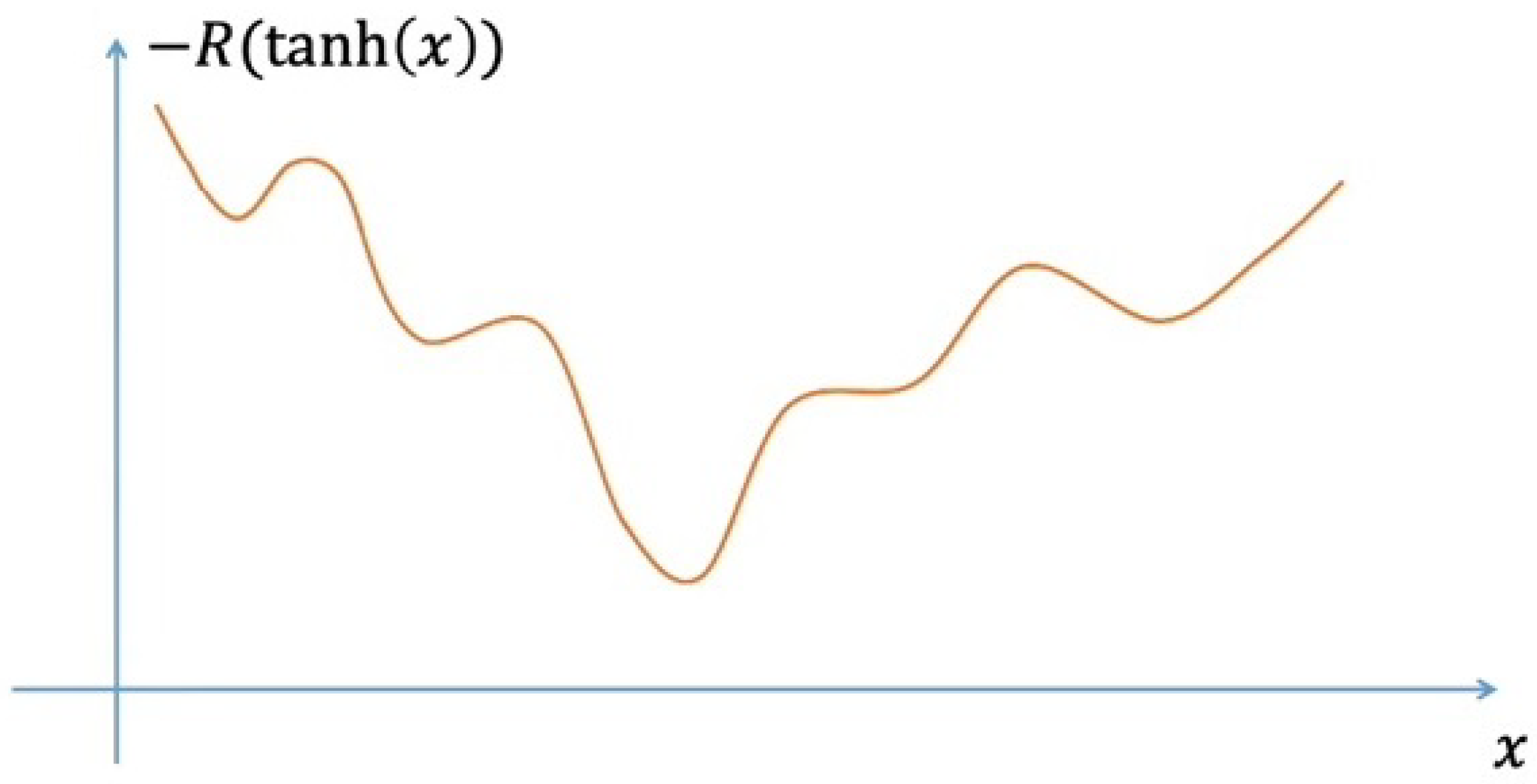
There are two stages in maximizing the rate equation. Stage 1 involves the initialization algorithm, Algorithm 1, and further optimization is carried out by Algorithm 2. So, along with this proposed technique, we have presented the rates for the genetic and gradient descent algorithms. The optimization problem is non-convex, where each IRS element is in a binary discrete state −1,+1. We must relax the discrete space to continuous space [−1,+1] to facilitate the gradient search. Further, we must meet this bounded continuous space to unbounded continuous search space over an entire real number line. So, the data rate function R mentioned in Equation (14) is used to define the cost function of gradient descent, as in Equation (17).
C ( x ) = R ( tanh ( x ) )
The binary nature of IRS fits well with the genetic algorithm. It also takes less time than gradient descent. We have to enforce the periodicity vertically for the final configuration for uneven configurations. This results in the overall highest data rate. So, using the genetic algorithm alone is the fastest way to achieve data rates up to 111.683 Mbps for LOS and 51.389 Mbps for NLOS. Figure 7 gives the plot for cost metric convergence, where the genetic algorithm is used together with gradient descent.
The genetic algorithm outputs a warm start for the gradient descent algorithm. So, running the genetic algorithm and gradient descent alternatively results in accurate, precise, high data rates, with  99.15 %  accuracy. In configuring the IRS for wireless communications, the algorithm operates with varying time requirements. Achieving the best possible configuration can take up to 6 min, reflecting the complexity and thoroughness of the calculation process. Alternatively, a faster configuration, completed in approximately 0.3 s, indicates a compromise in computational efficiency while still aiming to find a feasible solution. The selection between these timings depends on the need for precision versus expedience in achieving operational readiness for the IRS setup.
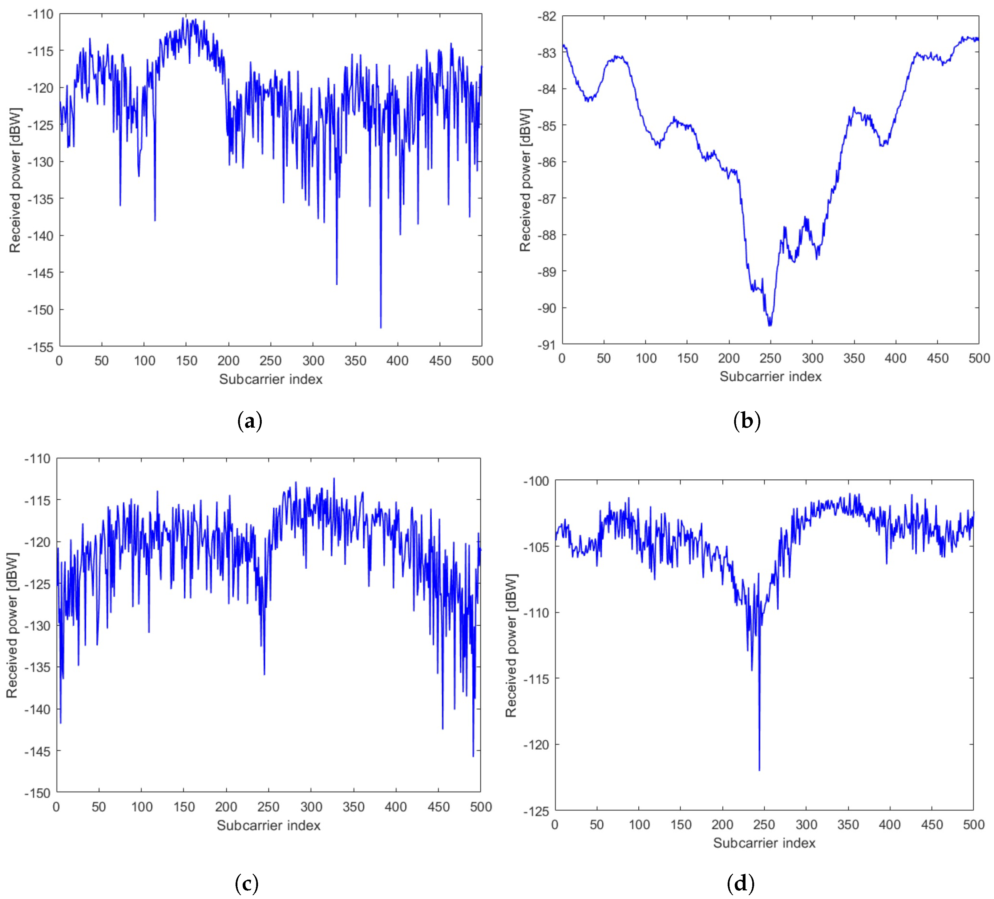
Figure 8 corresponds to the received signal power across all subcarriers for different users and IRS configurations. Figure 8a,b corresponds to the same LOS user, whereas Figure 8c,d relates to the same NLOS user. An IRS configuration is chosen without optimization during pilot transmission, keeping the diode condition in the Off state. In Figure 8a, The graph shows the received power fluctuating between approximately −115 dBW and −155 dBW across the subcarrier index. In Figure 8c, The graph shows the received power fluctuating between approximately −110 dBW and −145 dBW across the subcarrier index. These plots illustrate the received power levels without optimizing the IRS, providing a baseline for LOS and NLOS users. The rates are calculated using B = 10 MHz, P = 1 W, M = 20 and K = 500. The estimated variance of  N C  is 3.1614  ×   10 20 .
The rates for the pilot transmission and our optimized configuration, in comparison with other methods in the literature [34], all computed using channel estimation, are shown in Table 3. The work by our team, named Meta-Darpan as mentioned in [23], reached 10th position with 117.58 Mbits/s in the average metric scale. The algorithm is further improved in Algorithms 1 and 2 to achieve the proposed metric for the LOS and NLOS scenarios, as given in Table 3.
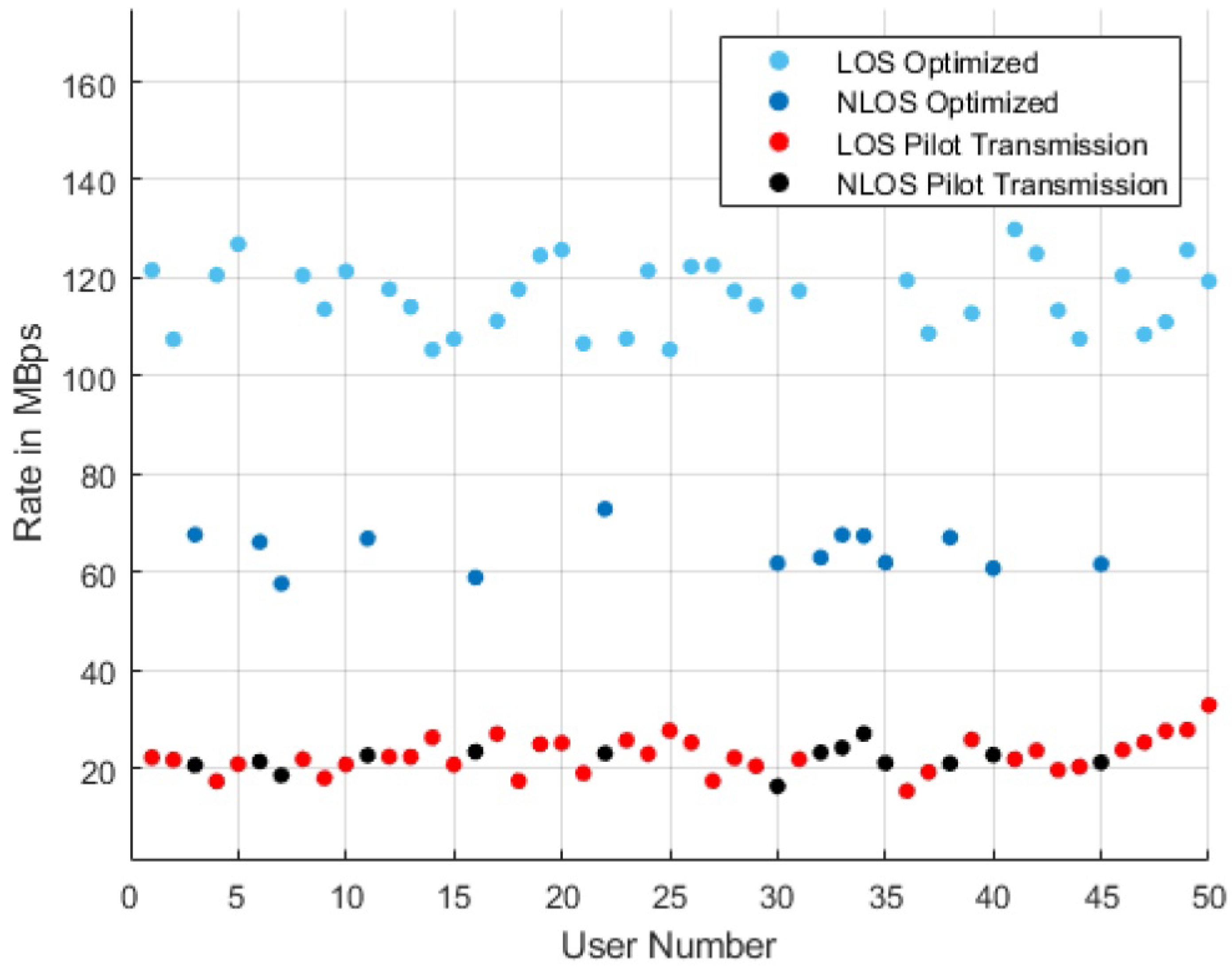
The rates are increased by approximately six and three times for LOS and NLOS users, respectively. We have considered 50 users located at different positions that are unknown. Figure 9 shows an improvement in the rate for all these 50 users. This work focused on developing algorithms for configuring IRS. To benchmark the methods used for IRS-aided wireless communications, the key methods included classical signal estimation techniques and evolutionary algorithms, which efficiently handled the combinatorial nature of the problem. We also considered frequency-selective fading and discrete state configurations (+90°/−90° phase shifts), and accounted for hardware imperfections like unbalanced reflection amplitudes and mutual coupling effects.

6. Conclusions

This work optimizes the IRS configuration to obtain a better data rate for the considered user with fixed transmit power. A low-complexity solution based on a greedy method has been proposed to achieve near-optimal performance. The simulation results validate the algorithm numerically. Our work has revealed that with the proposed algorithm, rates can be increased by six times and three times for LOS and NLOS users, respectively, compared to pilot transmission. The results are compared analytically with those obtained from other existing optimization algorithms with the same channel conditions, and with the proposed algorithm, a significant improvement is observed across LOS and NLOS users.

Author Contributions

Conceptualization, S.A.J.; methodology, S.A.J.; software, S.A.J., S.S.H., K.R. and A.C.; validation, S.A.J., S.S.H., P.K. and K.K.; formal analysis, S.A.J.; investigation, S.A.J.; resources, S.A.J.; data curation, S.A.J. and A.C.; writing—original draft preparation, S.A.J.; writing—review and editing, S.A.J., K.K. and P.K.; visualization, S.A.J.; supervision, P.K. and K.K; project administration, S.A.J.; funding acquisition, S.A.J., K.K. and P.K. All authors have read and agreed to the published version of the manuscript.

Funding

This research received no external funding.

Data Availability Statement

Data are contained within the article. The original contributions presented in the study are included in the article; further inquiries can be directed to the corresponding authors.

Conflicts of Interest

The authors declare no conflicts of interest.

References

  1. Kadir, E.A.; Shubair, R.; Rahim, S.K.A.; Himdi, M.; Kamarudin, M.R.; Rosa, S.L. B5G and 6G: Next Generation Wireless Communications Technologies, Demand and Challenges. In Proceedings of the 2021 International Congress of Advanced Technology and Engineering (ICOTEN), Taiz, Yemen, 4–5 July 2021; pp. 1–6. [Google Scholar] [CrossRef]
  2. Feng, Y.; Hu, Q.; Qu, K.; Yang, W.; Zheng, Y.; Chen, K. Reconfigurable Intelligent Surfaces: Design, Implementation, and Practical Demonstration. Electromagn. Sci. 2023, 1, 0020111. [Google Scholar] [CrossRef]
  3. Pitilakis, A.; Tsilipakos, O.; Liu, F.; Kossifos, K.M.; Tasolamprou, A.C.; Kwon, D.-H.; Mirmoosa, M.S.; Manessis, D.; Kantartzis, N.V.; Liaskos, C.; et al. A Multi-Functional Reconfigurable Metasurface: Electromagnetic Design Accounting for Fabrication Aspects. IEEE Trans. Antennas Propag. 2020, 69, 1440–1454. [Google Scholar] [CrossRef]
  4. Huang, C.; Zappone, A.; Alexandropoulos, G.C.; Debbah, M.; Yuen, C. Reconfigurable Intelligent Surfaces for Energy Efficiency in Wireless Communication. IEEE Trans. Wirel. Commun. 2019, 18, 4157–4170. [Google Scholar] [CrossRef]
  5. Sultana, A.; Fernando, X. Intelligent reflecting surface-aided device-to-device communication: A deep reinforcement learning approach. Future Internet 2022, 14, 256. [Google Scholar] [CrossRef]
  6. Okogbaa, F.C.; Ahmed, Q.Z.; Khan, F.A.; Abbas, W.B.; Che, F.; Zaidi, S.A.R.; Alade, T. Design and application of intelligent reflecting surface (IRS) for beyond 5G wireless networks: A review. Sensors 2022, 22, 2436. [Google Scholar] [CrossRef] [PubMed]
  7. Janawade, S.A.; Prabu, K.; Krishnamoorthy, K. Switchable Wideband phase Gradient Beam Steering Reflector/Absorber for Applications such as Intelligent Reflecting Surfaces. In Proceedings of the 2023 3rd International Conference on Intelligent Technologies (CONIT), Hubli, India, 23–25 June 2023; pp. 1–5. [Google Scholar] [CrossRef]
  8. Björnson, E.; Sanguinetti, L.; Wymeersch, H.; Hoydis, J.; Marzetta, T.L. Massive MIMO is a reality—What is next? Digit. Signal Process. 2019, 94, 3–20. [Google Scholar] [CrossRef]
  9. Abeywickrama, S.; Zhang, R.; Wu, Q.; Yuen, C. Intelligent Reflecting Surface: Practical Phase Shift Model and Beamforming Optimization. IEEE Trans. Commun. 2020, 68, 5849–5863. [Google Scholar] [CrossRef]
  10. Björnson, E.; Eldar, Y.C.; Larsson, E.G.; Lozano, A.; Poor, H.V. Twenty-Five Years of Signal Processing Advances for Multiantenna Communications: From theory to mainstream technology. IEEE Signal Process. Mag. 2023, 40, 107–117. [Google Scholar] [CrossRef]
  11. An, J.; Xu, C.; Gan, L.; Hanzo, L. Low-complexity channel estimation and passive beamforming for RIS-assisted MIMO systems relying on discrete phase shifts. IEEE Trans. Commun. 2021, 70, 1245–1260. [Google Scholar] [CrossRef]
  12. An, J.; Xu, C.; Wu, Q.; Ng, D.W.K.; Renzo, M.D.; Yuen, C.; Hanzo, L. Codebook-based solutions for reconfigurable intelligent surfaces and their open challenges. IEEE Wirel. Commun. 2022, 31, 134–141. [Google Scholar] [CrossRef]
  13. An, J.; Xu, C.; Ng, D.W.K.; Alexandropoulos, G.C.; Huang, C.; Yuen, C.; Hanzo, L. Stacked intelligent metasurfaces for efficient holographic MIMO communications in 6G. IEEE J. Sel. Areas Commun. 2023, 41, 2380–2396. [Google Scholar] [CrossRef]
  14. An, J.; Yuen, C.; Xu, C.; Li, H.; Ng, D.W.K.; Renzo, M.D.; Debbah, M.; Hanzo, L. Stacked intelligent metasurface-aided MIMO transceiver design. IEEE Wirel. Commun. 2024, 1–9. [Google Scholar] [CrossRef]
  15. Xu, C.; An, J.; Bai, T.; Sugiura, S.; Maunder, R.G.; Wang, Z.; Yang, L.; Hanzo, L. Channel estimation for reconfigurable intelligent surface assisted high-mobility wireless systems. IEEE Trans. Veh. Technol. 2022, 72, 718–734. [Google Scholar] [CrossRef]
  16. Xu, C.; An, J.; Bai, T.; Xiang, L.; Sugiura, S.; Maunder, R.G.; Yang, L.; Hanzo, L. Reconfigurable intelligent surface assisted multi-carrier wireless systems for doubly selective high-mobility Ricean channels. IEEE Trans. Veh. Technol. 2022, 71, 4023–4041. [Google Scholar] [CrossRef]
  17. An, J.; Wu, Q.; Yuen, C. Scalable channel estimation and reflection optimization for reconfigurable intelligent surface-enhanced OFDM systems. IEEE Wirel. Commun. Lett. 2022, 11, 796–800. [Google Scholar] [CrossRef]
  18. An, J.; Xu, C.; Ng, D.W.K.; Yuen, C.; Hanzo, L. Adjustable-delay RIS is capable of improving OFDM systems. IEEE Trans. Veh. Technol. 2024, 73, 9927–9942. [Google Scholar] [CrossRef]
  19. Özdogan, Ö.; Björnson, E.; Larsson, E.G. Intelligent Reflecting Surfaces: Physics, Propagation, and Pathloss Modeling. IEEE Wirel. Commun. Lett. 2020, 9, 581–585. [Google Scholar] [CrossRef]
  20. Pei, X.; Yin, H.; Tan, L.; Cao, L.; Li, Z.; Wang, K.; Zhang, K.; Bjornson, E. RIS-Aided Wireless Communications: Prototyping, Adaptive Beamforming, and Indoor/Outdoor Field Trials. IEEE Trans. Commun. 2021, 69, 8627–8640. [Google Scholar] [CrossRef]
  21. Shen, H.; Xu, W.; Gong, S.; He, Z.; Zhao, C. Secrecy Rate Maximization for Intelligent Reflecting Surface Assisted Multi-Antenna Communications. IEEE Commun. Lett. 2019, 23, 1488–1492. [Google Scholar] [CrossRef]
  22. Cui, M.; Zhang, G.; Zhang, R. Secure Wireless Communication via Intelligent Reflecting Surface. IEEE Wirel. Commun. Lett. 2019, 8, 1410–1414. [Google Scholar] [CrossRef]
  23. Björnson, E.; Marcenaro, L. Configuring an Intelligent Reflecting Surface for Wireless Communications: Highlights from the 2021 IEEE Signal Processing Cup student competition [SP Competitions]. IEEE Signal Process. Mag. 2022, 39, 126–131. [Google Scholar] [CrossRef]
  24. Wu, Q.; Zhang, R. Intelligent reflecting surface enhanced wireless network: Joint active and passive beamforming design. In Proceedings of the IEEE Global Communications Conference (GLOBECOM), Abu Dhabi, United Arab Emirates, 9–13 December 2018; pp. 1–6. [Google Scholar]
  25. Ma, D.; Li, L.; Ren, H.; Wang, D.; Li, X.; Han, Z. Distributed Rate Optimization for Intelligent Reflecting Surface with Federated Learning. In Proceedings of the 2020 IEEE International Conference on Communications Workshops (ICC Workshops), Dublin, Ireland, 7–11 December 2020; pp. 1–6. [Google Scholar] [CrossRef]
  26. Guo, H.; Liang, Y.-C.; Chen, J.; Larsson, E.G. Weighted Sum-Rate Maximization for Intelligent Reflecting Surface Enhanced Wireless Networks. In Proceedings of the 2019 IEEE Global Communications Conference (GLOBECOM), Waikoloa, HI, USA, 9–13 December 2019; pp. 1–6. [Google Scholar] [CrossRef]
  27. Wu, Q.; Zhang, R. Intelligent Reflecting Surface Enhanced Wireless Network via Joint Active and Passive Beamforming. IEEE Trans. Wirel. Commun. 2019, 18, 5394–5409. [Google Scholar] [CrossRef]
  28. Zheng, B.; Wu, Q.; Zhang, R. Intelligent Reflecting Surface-Assisted Multiple Access with User Pairing: NOMA or OMA? IEEE Commun. Lett. 2020, 24, 753–757. [Google Scholar] [CrossRef]
  29. Björnson, E.; Wymeersch, H.; Matthiesen, B.; Popovski, P.; Sanguinetti, L.; de Carvalho, E. Reconfigurable Intelligent Surfaces: A signal processing perspective with wireless applications. IEEE Signal Process. Mag. 2022, 39, 135–158. [Google Scholar] [CrossRef]
  30. Yang, Y.; Zheng, B.; Zhang, S.; Zhang, R. Intelligent Reflecting Surface Meets OFDM: Protocol Design and Rate Maximization. IEEE Trans. Commun. 2020, 68, 4522–4535. [Google Scholar] [CrossRef]
  31. Popovski, P. Wireless Connectivity: An Intuitive and Fundamental Guide; Wiley: Hoboken, NJ, USA, 2020. [Google Scholar]
  32. Goldsmith, A. Wireless Communications; Cambridge Univ. Press: Cambridge, UK, 2005. [Google Scholar]
  33. Bjoernson, E. Optimizing a Binary Intelligent Reflecting Surface for OFDM Communications under Mutual Coupling. In Proceedings of the WSA 2021; 25th International ITG Workshop on Smart Antennas, French Riviera, France, 10–12 November 2021; pp. 1–6. [Google Scholar]
  34. Man, K.F.; Tang, K.S.; Kwong, S. Genetic algorithms: Concepts and applications [in engineering design]. IEEE Trans. Ind. Electron. 1996, 43, 519–534. [Google Scholar] [CrossRef]
  35. Tiwari, R.; Venkateswaran, K. Configuring an Intelligent Reflecting Surface using Strongest Tap Maximization Heuristic Technique. In Proceedings of the 2022 International Conference on Signal and Information Processing (IConSIP), Pune, India, 26–27 August 2022; pp. 1–5. [Google Scholar] [CrossRef]
  36. Cht, K.T.Y.; Tiwari, R.; Venkateswaran, K. Power Allocation of Multiple subcarriers using Water Filling algorithm for RIS Aided Communication Sytsems. In Proceedings of the 2021 Third International Conference on Inventive Research in Computing Applications (ICIRCA), Coimbatore, India, 2–4 September 2021; pp. 308–311. [Google Scholar] [CrossRef]
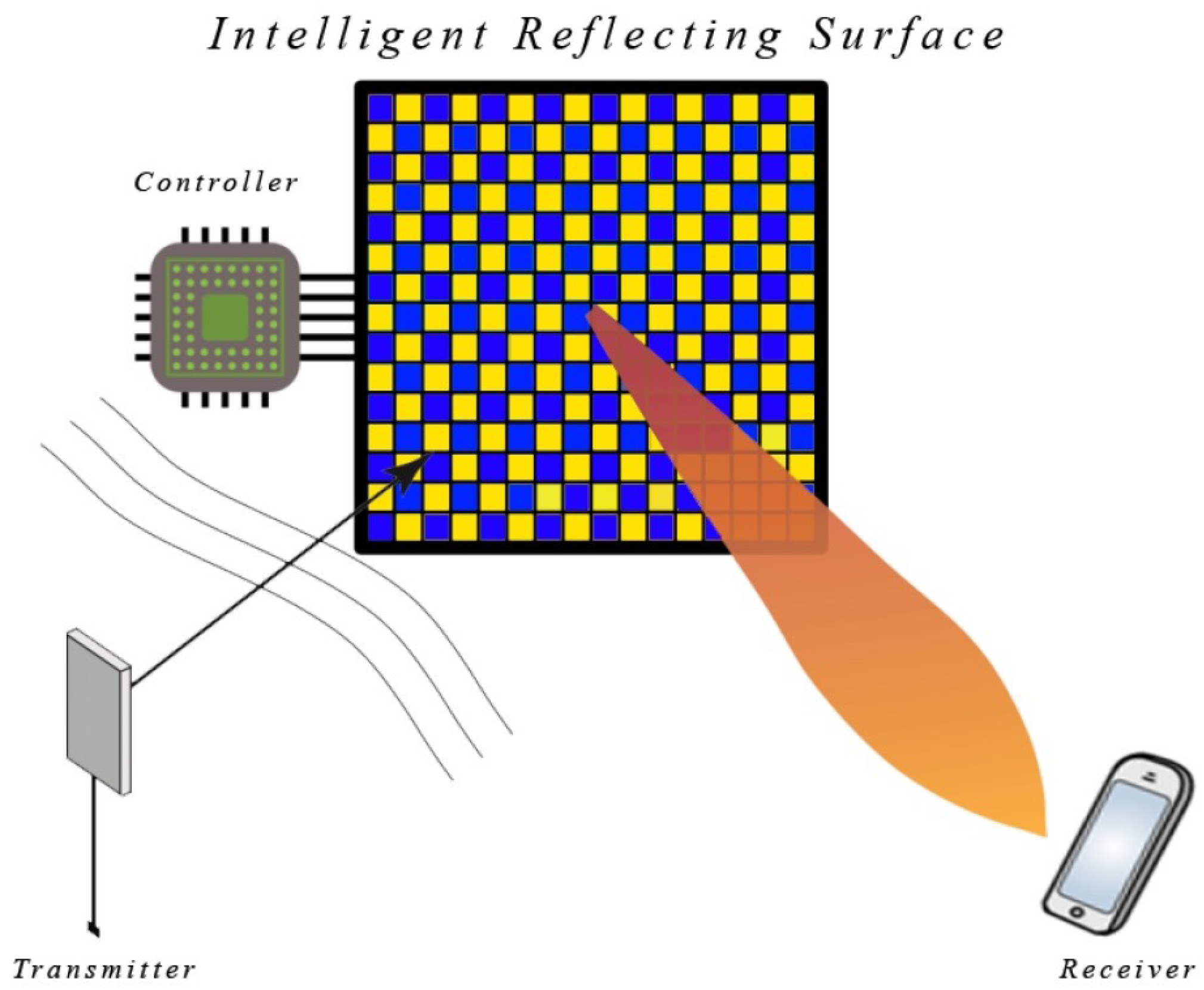
Figure 1. Model of an IRS.
Futureinternet 16 00272 g001
Figure 2. Reflecting surface horizontal and vertical index  64 × 64  cell estimation.
Futureinternet 16 00272 g002
Figure 3. Mutual coupling plot at the center of the cell arrangement.
Futureinternet 16 00272 g003
Figure 4. Phase plot for the cell arrangement.
Futureinternet 16 00272 g004
Figure 5. Amplitude plot for the cell arrangement.
Futureinternet 16 00272 g005
Figure 6. The path loss of the reflected path.
Futureinternet 16 00272 g006
Figure 7. The convergence of the algorithm.
Futureinternet 16 00272 g007
Figure 8. Received signal power across all subcarriers. (a) LOS user with pilot transmission, (b) LOS user with optimized IRS configuration, (c) NLOS user with pilot transmission, (d) NLOS user with optimized IRS configuration.
Futureinternet 16 00272 g008
Figure 9. Rate improvements for different users.
Futureinternet 16 00272 g009
Table 2. Glossary of Terms and Notations  used.
  h d BS-user (direct) channel
  a n The n-th IRS element’s BS-IRS channel
  b n The n-th IRS element’s IRS-user channel
  θ IRS reflection coefficients
  ϕ Reflection coefficient of the IRS
  α n Propagation Loss
  β n Propagation Loss
  δ t Dirac delta function
  f c Carrier Frequency
  Z Received Signal
  F Fourier Transformation on signal
  λ Signal Wavelength
  h θ Overall impulse response of the channel
  H d Frequency response of BS-User (direct) channel
  V Frequency response of the BS-IRS-User channel
  ω Circularly Symmetric Gaussian Noise (CSGN)
  N C F.T. of  ω  with variance  σ 2
Table 3. Weighted sum rates across all subcarriers (MBits/s).
Sl. No.AlgorithmLOSNLOS
1Pilot Transmission [23]21.25521.469
2Gradient Descent111.68351.389
3Genetic Algorithm117.38455.521
4Heuristic Technique [35]10050
5Water-filling Algorithm [36]119.178 (26th configuration)Author not verified
6Proposed Approach126.89066.093
Disclaimer/Publisher’s Note: The statements, opinions and data contained in all publications are solely those of the individual author(s) and contributor(s) and not of MDPI and/or the editor(s). MDPI and/or the editor(s) disclaim responsibility for any injury to people or property resulting from any ideas, methods, instructions or products referred to in the content.