1. Introduction
UAVs, commonly called drones, have revolutionized the way aerial operations are conducted. Originally developed for military surveillance purposes [
1], UAVs have experienced a drastic increase in usage during recent years and have become a valuable tool in various civilian industries [
2] (e.g., traffic management, agriculture, surveillance and security, delivery services, and search and rescue, etc.) due to advancements in technology that have made them inexpensive, easy to deploy, and operate in hazardous or inaccessible environments. However, despite the benefits of UAVs, there are some limitations that can affect their operational effectiveness. The current IP architecture is identified as one of these limitations [
3].
The current IP architecture was originally designed for communication among fixed devices on the Internet, and it focuses on the location of the devices rather than the data being transmitted. However, in recent years, it has become evident that the current IP architecture is not as well-suited to the demands of the modern Internet [
4], which includes heterogeneous communication and a wide variety of highly mobile devices and vehicles such as satellites and UAVs, which have different requirements and characteristics compared to traditional fixed devices. In addition, many modern aircraft, including UAVs, are often employed to gather sensitive data for surveillance, research, and monitoring purposes. Collecting such data requires robust security measures to safeguard against security attacks and ensure their confidentiality and integrity. To this end, several overlay patches have been implemented to address security and mobility issues. Nevertheless, the IP architecture still faces challenges in providing seamless and efficient mobility support for all types of devices and applications. Moreover, overlay patches might not be sufficient for protecting against emerging threats [
5]. This hinders the safe and secure use of UAVs for sensitive applications like military operations or privacy-sensitive contexts.
In the last decade, the NDN architecture [
6] has gained much research attention. It has been proposed as one of the promising future Internet architectures to overcome the current vulnerabilities and cope with the challenges [
7] (e.g., addressing, name resolution, security, and privacy) of the IP Internet architecture. NDN is an information-centric networking architecture that changes the communication semantics by focusing on retrieving data by a given unique name rather than location address. Thanks to the built-in security, multi-path forwarding, consumer-driven communication, in-network caching, and name-based routing features, NDN has proven to be a suitable information-centric networking architecture choice for UAV communication [
8,
9].
As a result of the built-in features of NDN, the mobility of devices requesting data (consumers) is inherently supported, thanks to its consumer-driven communication feature [
10], where consumers only need to reissue requests from their new location without updating their locations or establishing a new connection. In contrast, producer (devices generating data) mobility management remains one of the significant challenges due to NDN’s content-centric design, where data retrieval is based on content names rather than the location of devices. Accordingly, when the producer changes their Point of Attachment (PoA), they may become unreachable for a while until the relevant routers in the network update their information to the producers’ new location. Furthermore, UAVs, as producers of data, introduce additional challenges for mobility management due to their real-time communication requirements, the ineffective NDN in-network caching feature to support low-latency data, and the UAVs’ ability to move quickly and unpredictably, leading to frequent handoffs, which may result in increased latency and packet loss.
Many strategies have been proposed in the literature to address the producer mobility issue, which can be divided into two broad approaches: Anchor-less [
11,
12,
13,
14,
15,
16] and Anchor-based [
17,
18,
19,
20,
21]. In the Anchor-based approach, a fixed network node is used as a Domain Name System (DNS) server, a mapping server, or a rendezvous node to redirect packets toward the Mobile Producer (MP) or as a depot to store the producer’s data before a handoff occurs. In contrast, in the Anchor-less approach, producer mobility is generally supported using updates of the forwarding information base table in the routers either between producers and consumers or between the producer’s new and old PoA after handoff occurs.
This paper aims to design a strategy for supporting UAV mobility and ensuring seamless low-latency data delivery in NDN architecture.
Table 1 lists the key abbreviations used in this article with their definitions.
The main contributions of this work are as follows:
- (a)
We propose a low-overhead strategy based on strategically deployed decentralized cooperative Anchors, which proactively forwards the consumer’s packet toward producers when handoff occurs to achieve seamless data delivery with minimum packet loss and delay.
- (b)
We introduce a new forwarding strategy that combines the NDN’s default forwarding and the location-based forwarding strategy.
- (c)
A Kalman filter method is used to predict the UAV’s location coordinates after the handoff.
- (d)
Using a realistic scenario, we implemented and evaluated the performance of the DMMS against two well-known solutions, Kite [
17] and MAP-ME [
13].
This paper is structured as follows.
Section 2 provides a concise overview of the NDN architecture, its forwarding pipeline, the associated mobility issues, and a review of the pertinent literature. In
Section 3, the design and functionalities of DMMS are detailed.
Section 4 offers an evaluation of our proposed solution, examining its performance and effectiveness. Lastly,
Section 5 concludes the paper and outlines potential avenues for future research in this domain.
2. NDN Background and Related Work
2.1. Named Data Networking Architecture
The communication philosophy of NDN is fundamentally based on three types of entities: consumers, producers, and routers. When a consumer wants to request content, it sends an Interest Packet (Inpt) containing the content’s name. This Inpt is routed through the network towards the data producer, which responds with a Data packet containing the requested content. Each router in the NDN maintains three crucial tables: the Pending Interest Table (PIT), Forwarding Information Base (FIB), and Content Store (CS). These tables work together to optimize content delivery in NDN by efficiently managing the Inpt and Data packet within the network. Once receiving an Inpt, a router first checks its CS (a cache that stores data requested before) to see if it already has a copy of the requested data. If a match is found in the CS, the router immediately satisfies the received Inpt. If the CS check fails to find the desired data, implying that no cached copy of the required content exists, the router then performs a lookup on the PIT (which keeps track of all the Inpts that have been forwarded but have not yet been satisfied) to verify whether it has an entry for the received Inpt. If an entry is found in the PIT, the router will add the received interface ID to the PIT entry, and the Inpt will be dropped. Otherwise, the router then performs a name-based longest prefix match lookup in its FIB (which contains the forwarding information for each content name) to determine the interface to forward the Inpt toward the producer. If a match is found for the content name in one of the FIB entries, the router then creates a new PIT entry for the Inpt using the received interface ID and Inpt’s content name, and the Inpt is forwarded upstream. This process is repeated until the Inpt reaches the producer that replies with a Data packet, which follows the reverse path stored in the PIT entries across the routers, taken by the Inpt, back to the consumer. In the case when no longest prefix match is found, then the Inpt is forwarded according to the forwarding strategy used.
2.2. Mobility in Named Data Networking
In NDN, the mobility of UAVs can be classified based on their applications into two distinct types: producer and consumer mobility. The latter is more easily managed due to inherent features of the NDN architecture design, like in-network caching, multi-path forwarding, and consumer-driven communication. For instance, when a consumer changes its PoA, it can resend Inpts from its new location without updating the location or establishing a new connection. This Inpt can be satisfied either by intermediate routers that have previously cached the data or by the producer. On the other hand, the NDN architecture faces difficulties in effectively supporting producer mobility. This is mainly because Inpts are forwarded based on the content’s name, not the producer’s location. When a producer moves to a new PoA, consumer Inpts are initially sent toward the producer’s previous location due to the outdated FIB of the relevant routers. As a result, the Inpts cannot reach the newly moved producer until these routers’ FIBs are updated to reflect the producer’s new location. The time taken to update all relevant FIBs can cause significant delay in communication and increase packet loss, which is unacceptable in scenarios that require low-latency communication.
2.3. Related Work
Several survey studies [
22,
23,
24,
25] have been conducted to categorize the producer mobility support strategies into different approaches based on the technique used and their functions and features. However, these strategies can be generally classified into two broad distinct categories: Anchor-less and Anchor-based approaches.
2.3.1. Anchor-Less Approach
In the Anchor-less approach, managing producer mobility is achieved without the assistance of a specific node in the network. Various strategies are proposed to ensure the effective delivery of Inpts to an MP. These strategies may involve dynamically updating the FIB tables after a producer’s handoff, caching the producer’s content on a neighboring router before the producer’s handoff, or employing an optimal broadcast to reach the MP.
Hussaini et al. [
11] proposed a solution that involves the MP broadcasting a special Inpt (mobility Interest) throughout its new location. This Inpt carries the producer’s location prefix information, which is used to update the FIB tables of routers within the producer’s domain. Additionally, if the producer and consumers are located in different domains, the mobility Interest message is also used to update the FIB tables of routers in neighboring domains.
The scheme outlined in [
12] introduces a forwarding strategy designed to support producer mobility within NDN-IoT. In this scheme, each PoA continuously sends periodic Inpts to monitor the status of all attached sensors. When the PoA does not receive a response from a sensor, it sends a Recovery packet to remove the forwarding information associated with this sensor from the routers along the path between the producer and the consumer. Upon detecting the connection of a new sensor, the PoA sends a Recovery packet with the aim of creating a new FIB entry leading to this sensor. This Recovery packet is forwarded to the consumer using the longest prefix match method.
Augé et al. [
13,
14] proposed “MAP-ME”, a solution for supporting producer mobility in real-time communication by dynamically updating the FIB table in minimal routers in the network. In [
13], when the MP changes the PoA, it sends a special update Inpt from the new PoA to the old PoA to update the router’s FIB along the path between the new and old PoA. A new variant of the MAP-ME scheme was proposed in [
14] to address the producer micro-mobility, which includes an additional protocol named “Notification/Discovery” to alleviate the issues of Inpt update dropping or late updating of the FIB due to network latency, which can be lead to an increase in packet loss. An Inpt notification is left by the producer at the old PoA to redirect the future consumer’s Inpts through a broadcasting method until they meet the path toward the producer. A significant shortcoming of MAP-ME is it suffers from a triangular routing problem. It is worth noting that MAP-ME is related to topology-based methods.
The scheme proposed in [
15] focuses on supporting producer mobility in NDN by leveraging the in-network caching feature. The main idea of this scheme is to predict the next location of an MP and proactively cache the most frequently requested data in the router nearest to the consumer before the producer’s handover occurs.
The work described in [
16] presents a scheme designed to reduce the delay and minimize packet loss caused by producer mobility in real-time remote health-monitoring systems based on NDN. The main idea of the proposed scheme is to register the MP in both the current PoA and the nearest PoA. In this way, the MP establishes connections and maintains a presence in the network even when moving between different PoAs. However, it is worth noting that inter-AS mobility brings a large signaling overhead since the proposed scheme uses a broadcasting forwarding strategy to locate a producer each time it crosses between autonomous systems. Furthermore, registering a large number of MPs with multiple PoAs can lead to a significant increase in the size of FIB tables at PoAs.
2.3.2. Anchor-Based Approach
To support producer mobility, a solution proposed by the NDN Research Labs [
17], denoted as “Kite”, involves using a Rendezvous Server (RVS) as an intermediary to facilitate communication between consumers and producers. This strategy involves publishing the producer’s content under a reachable RVS prefix. When the producer changes PoA, it sends a Trace Inpt (TI) to the RVS. In response, a Trace Data Packet (TD) is sent back to the producer, which follows the same path as the TI. When intermediate routers receive the TD, they create a FIB entry for the MP using the data name extracted from the TD and the face from which the TD is received to create a hop-by-hop path between the MP and the RVS. Thus, when the consumer wants to fetch data from the producer, it sends Inpt initially to the RVS. Subsequently, the RVS forwards this Inpt towards the MP along the path that was created earlier during the handoff process. However, the Kite scheme introduces two main drawbacks. Firstly, it brings a large signaling overhead due to the necessity of maintaining the path to the MP in the Trace FIB table. Secondly, frequent handoffs by the MP can lead to the “stale path” problem, where outdated path information results in increased packet loss.
The authors of [
18] proposed a redirection-based strategy to support content source mobility in Content-Centric Networking (CCN) to reduce routing overhead caused by updates to the router’s FIB. When a content source moves to a new PoA, it sends a special Inpt to its home domain router, which acts as a home agent in the context of mobile IP. This Inpt contains the prefix advertised by the new PoA. Subsequently, when the home domain router receives a consumer’s Inpt, it encapsulates it within a new Inpt using the prefix of the new PoA as the content name. This encapsulated Inpt is then forwarded to the content source based on the content name associated with the new PoA. However, this strategy suffers from the path stretch problem, as all Inpts must pass through the content source’s home domain to reach it, potentially increasing latency. Additionally, Inpt encapsulation introduces additional complexity to the CCN protocol, making it more challenging to implement and maintain.
Kim et al. [
19] presented an on-demand Anchor strategy to support producer mobility. In this strategy, when the MP switches to a new PoA, it sends an Inpt (mobility update) containing its content name to an immobile Anchor router, establishing a trace path with the Anchor. As the consumer’s Inpts reach the previous PoA of the MP, rather than being dropped, they are redirected to the Anchor router. Subsequently, the Anchor router forwards the Inpts toward the producer’s new location. However, this strategy does not specify Anchor placement in the network, potentially leading to path stretch due to the consumer’s Inpt redirection through the Anchors.
The work described in [
20] proposes a pulling-based strategy, denoted “ProPull”, to support producer mobility for real-time content delivery. This strategy aims to provide the best possible quality of service for consumers by ensuring uninterrupted multi-media transmission during producer mobility while minimizing signaling overhead costs. The ProPull strategy achieves this by pulling Inpts from the producer’s old PoA to the new PoA. When the producer predicts a handover, it sends a special Inpt to the current PoA to obtain its prefix. Once connected to the new PoA, the producer communicates with the old PoA by exchanging special messages called Propaganda Inpts and Propaganda Data packets. This communication establishes a temporary forwarding path between the old and new PoA, ensuring that consumer Inpts are pulled efficiently to the producer’s new location. However, the ProPull strategy introduces high signaling overhead due to exchanging Propaganda Inpts and Propaganda Data packets during each producer relocation.
To reduce handover latency in real-time communication scenarios, a scheme proposed in [
21] utilizes the producer’s future location prediction to ensure seamless producer mobility. When a producer detects a handoff event by monitoring the signal strength from the current PoA, it sends a special Inpt to the current PoA, which then predicts the best PoA candidate the producer is expected to connect to after the handoff. Once the handoff is completed and the producer successfully connects to the new PoA, the consumer’s Inpt is redirected toward the new PoA from the old PoA. However, using a redirection strategy can result in path stretching, leading to increased latency. Furthermore, when the prediction of a producer’s future location goes wrong, the new PoA broadcasts the producer’s reachable prefix throughout the network, resulting in significant signaling overhead and congestion.
3. Proposed Solution
In this section, we introduce the DMMS, designed to minimize the impacts of the producer’s mobility in content delivery in terms of delay and packet loss using minimal signaling overhead. Our strategy relies on three components:
A distributed cooperative strategically deployed Anchor, which proactively forwards the consumers’ packet toward MPs when handoff occurs to achieve seamless data delivery with minimum packet loss and delay.
A forwarding strategy that combines the NDN’s default forwarding and the location-based forwarding strategy for improving data delivery.
A location prediction technique to anticipate the producer’s future location coordinates before a handoff event occurs, which allows for proactive forwarding of consumers’ Inpts through the Anchor to the coordinates of the next PoA, where the producer is expected to be connected after the handoff.
We separately detail in this section the Distributed Anchor design, the forwarding strategy, and the producer’s location prediction technique.
3.1. Distributed Anchor Design
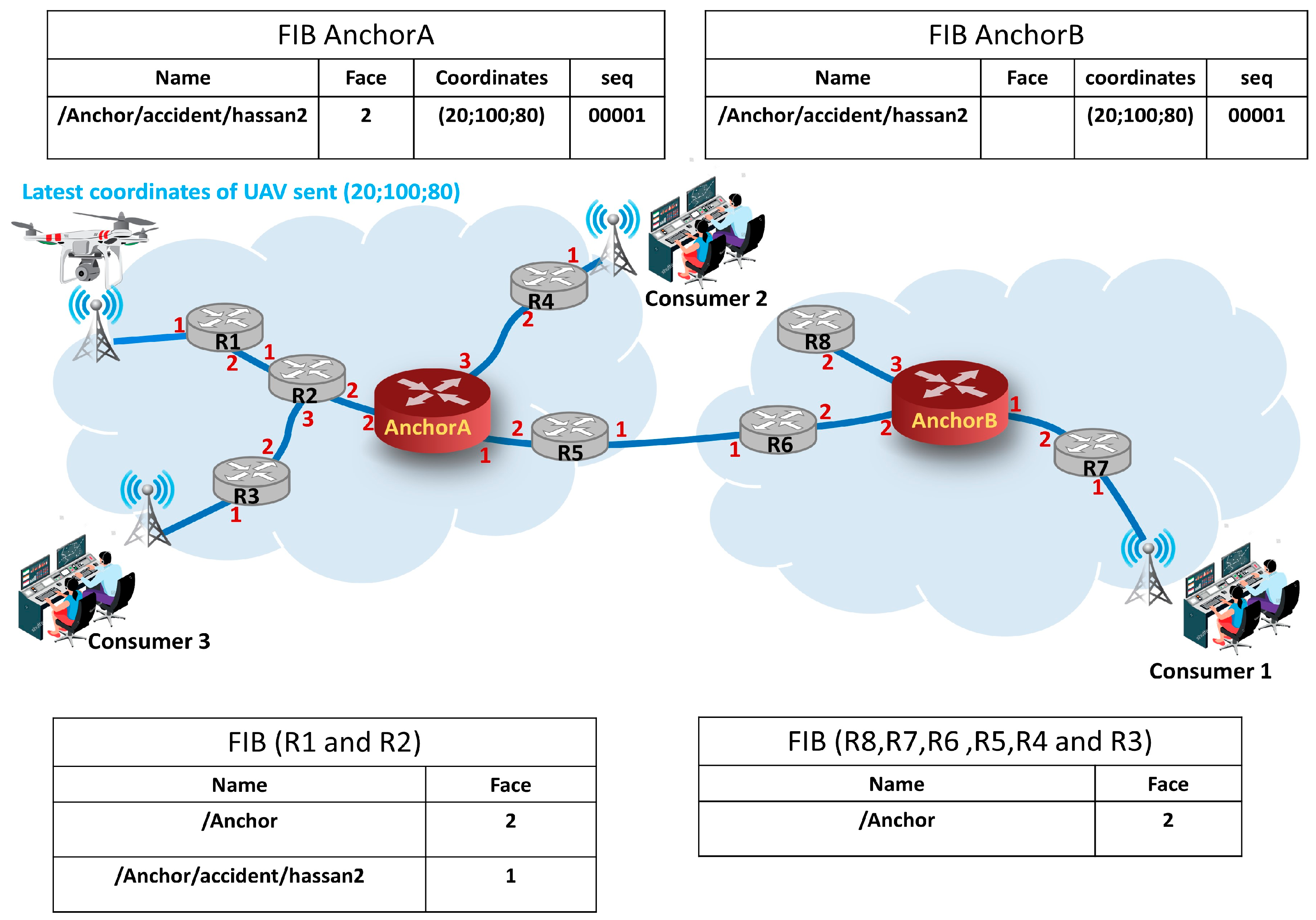
In the DMMS, distributed synchronized Anchors are strategically placed throughout the network. These Anchors act as rendezvous nodes between consumers and producers, where the Anchor redirects consumers’ Inpts toward the producer when a direct path is not found toward the producer with minimal path stretch. Each Anchor operates as a regular NDN router with the same functionalities and maintains the same structure with a slight modification to the FIB entries. This modification includes two additional fields, namely “coordinates” and “seq”. The “coordinates” field is used to store the coordinates of the producer’s location or the predicted one, while the “seq” field is a sequence number used to maintain the consistency of the producer’s coordinate information among Anchors and prevent forwarding loops during producer’s notification message propagation (e.g., AnchorA’s FIB in
Figure 1).
Regarding the inconsistencies in the producer’s coordinates among Anchors, they can be shared in real time by implementing synchronization protocols designed for distributed dataset synchronization in NDN, such as ChronoSync [
26], VectorSync [
27], or PSync [
28]. Alternatively, a producer’s handoff-driven mechanism is used to minimize unnecessary network traffic. When a producer handoff event occurs, it sends a special Inpt with a sequence number that serves as a unique identifier for the update, incremented with each handoff. This Inpt is then propagated to Anchors in the network to ensure that updates are applied in the correct order.
Like the IP anycast mechanism, the Anchors in the DMMS share and advertise the same routing prefix through the routing protocol within the network, which allows consumers to efficiently discover and connect with the nearest Anchor, regardless of their specific location within the network. Furthermore, to ensure the reachability of MP in the network, each MP is assigned a unique hierarchical name for its data, which uses the same Anchor prefix.
We present in
Figure 1 a comprehensive architecture concept. After an MP connects to a new PoA, it establishes a path between itself and the nearest Anchor. To request data from this MP, the consumer sends an Inpt containing the MP data name (e.g., in
Figure 1, the producer data name is “Anchor/accident/hassan2”). Once an intermediate router receives the Inpt, it checks its FIB to determine the Face with the longest prefix match. If a matched FIB entry to this Inpt is found, then the Inpt will be forwarded to the MP without the intervention of the Anchor (e.g., in
Figure 1, the Inpts of consumer 3 will be forwarded along R2 and R1 without reaching the Anchor). If a matched FIB entry does not exist, then the Inpt will be forwarded to the nearest Anchor. The Anchor then checks its FIB to determine the strategy to forward the Inpt, either using the NDN’s default forwarding (e.g., in
Figure 1, the Inpts of consumer 2 at AnchorA will be forwarded along the path AnchorA ⟶ R2 ⟶ R1 ⟶ PoA ⟶ producer) or using the location-based forwarding strategy (e.g., in
Figure 1, the Inpts of consumer 2 at AnchorB will be forwarded using location-based forwarding).
In fact, using Anchors in the network has a significant impact on increasing the path stretching between consumers and MPs compared to an Anchor-less approach. However, strategically positioned Anchors can effectively reduce the number of hops that the Inpts need to traverse to reach the MP, thereby minimizing latency and improving content delivery efficiency. The problem of selecting Anchor placements that can manage the producer mobility in a dense network can be viewed as a variant of the well-known k-center or p-median problems, which are optimization problems that involve selecting a subset of locations from a larger set of potential locations. However, solving this problem is challenging; as the network size grows, the number of possible Anchor placements increases exponentially, meaning that finding an optimal solution in polynomial time is unlikely, making it an NP-hard problem.
As a result, most researchers have focused on developing heuristic algorithms [
29] and simulation tools [
30] that can find near-optimal solutions in a reasonable amount of time. To determine the optimal Anchor placements that minimize the path stretch, we propose a method that involves partitioning the network into clusters based on network topology and selecting a router or Access point as an Anchor for each cluster based on its proximity to all routers and Access points within the cluster and its closeness to Anchors in other clusters to minimize intra-cluster and inter-cluster communication distances.
There are numerous clustering algorithms that can be applied to partitioning the network. Each algorithm has its own strengths and weaknesses, and some do not guarantee convergence to the optimal solution. A comprehensive survey of clustering algorithms can be found in [
31]. Our proposed method uses an iterative approach based on a simple and efficient clustering algorithm, namely the K-Medoids algorithm [
32]. It starts by selecting a k router as an initial cluster center router (medoids). The quality of this initial cluster is iteratively improved through a local search process based on minimizing both the distance between any cluster’s router and medoid and the distance between medoids. During each iteration, center routers are replaced by non-center ones, a process that continues until the intra-cluster and inter-cluster distances are reduced. However, the quality of the final clustering solution of our method may not usually be optimal since it is sensitive to the initial selection of the center cluster. Therefore, our method is executed multiple times with different random initialization. We then choose the optimal solution as Anchor placements. It is worth noting that determining the optimal number of Anchors for a given network is a complex problem that is out of the scope of this paper.
3.2. Forwarding Strategy
In this paper, we introduce a new forwarding approach that combines the NDN’s default forwarding strategy and the location-based forwarding strategy. As we have already mentioned, the data retrieval in NDN is based on content names without any location information of the device, resulting in the inability to handle producer mobility. That is why we propose integrating the location-based forwarding strategy, which can coexist with the NDN’s default forwarding strategy to maintain uninterrupted content delivery to consumers. When the MP initiates a handoff, it sends a RemovePath (RP) packet to notify the nearest Anchor about the predicted coordinates of its next location where it will be present after completing the handoff. Consumers remain unaware of the MP’s location change and send Inpts using NDN’s default forwarding strategy. Once an intermediate router receives the Inpt, it checks its FIB to determine the Face with the longest prefix match. If a matched FIB entry does not exist, the Inpt will be forwarded until it reaches the nearest Anchor. Subsequently, the Anchor checks its FIB to determine the strategy to forward this Inpt. If the path has been created between the MP and this Anchor before the reception of the Inpt, then the Anchor and all intermediate routers along the path use the NDN’s default forwarding strategy. Otherwise, the Anchor updates the X, Y, and Z coordinates in the Inpt with the producer’s predicted location coordinates and forward it using the location-based forwarding strategy.
Leveraging the location information of fixed routers and Access points, each router in the location-based forwarding strategy determines the next hop for the Inpt based on the Cartesian coordinates of its neighbors, where it calculates the Euclidean distance between its neighbors’ coordinates and the destination coordinates included in the Inpt and it forwards the packet to the nearest router to the destination coordinates, ensuring the shortest path to the MP.
To implement the location-based forwarding strategy without modifying the Inpt structure, we use the “GeoTag” header field within the Inpt, introduced in the second version of the NDN Link Adaptation Protocol [
33]; this predefined 3-byte field is specifically designated for including some location information in Inpt. We assume that routers and Access points involved in the network are stationary and possess prior knowledge of each other’s Cartesian locations.
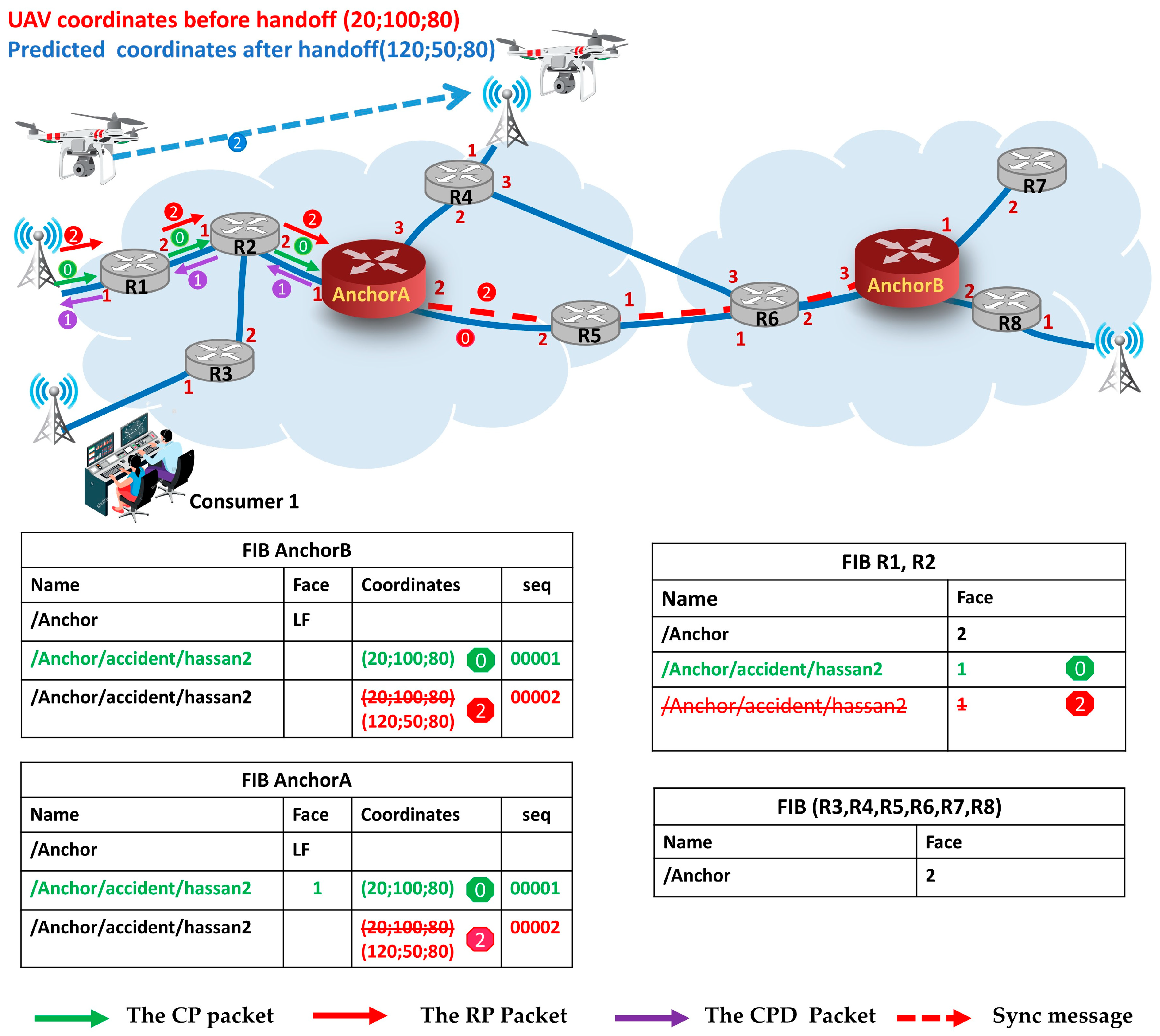
3.2.1. CreatePath and RemovePath Packet Forwarding
To efficiently implement our mobility management scheme, we use two types of Inpts:
(1) The CreatePath (CP) packet is an Inpt used to announce the producer’s connection to the network, which includes a Cartesian coordinate representing the producer’s location. Its purpose is to establish a path between the producer and Anchor and to notify the Anchors about the producer’s location. This packet is specifically sent to the nearest Anchor in two scenarios:
When a new producer connects to the network for the first time and when the MP cannot receive the Inpts after the handoff due to the failure to predict its destination coordinates. Like a regular Inpt structure, the CP packet uses a content name in the form of “Anchorprefix/CreatePath/producerDataName”, where the “Anchorprefix” refers to the prefix advertised by the Anchors, “producerDataName” represents the name of the producer’s data, while “CreatePath” serves as a special identifier that allows all routers to identify the packet as a request to establish the path between producer and an Anchor and handle it accordingly. Upon receiving the CP packet (step 0 in
Figure 2), an intermediate router (e.g., R2 in
Figure 2) creates a FIB entry using the incoming Face through which the CP packet arrives at the router and the extracted name from the CP packet name by removing the “CreatePath” identifier. This ensures that subsequent Inpts from consumers can be routed along the established path towards the producer without the intervention of an Anchor, particularly where the path between the MP and consumer is stretched to the Anchor (Inpts of consumer 1 in
Figure 2). To avoid failures in establishing the path between the MP and Anchor, a CreatePathData (CPD) packet (step 1 in
Figure 2) is used as an acknowledgment from the Anchor to the MP, confirming the receipt of the CP packet.
(2) The RemovePath Packet is an Inpt that serves a dual purpose: (1) updating the FIB entry associated with the producer’s data name in the Anchor with the producer’s predicted location; (2) removing the outdated FIB entry in the routers along the path between the producer and the nearest Anchor that may have been created before. Like the CP packet, the RP packet uses the same content name format, “Anchor prefix/RemovePath/producerDataName”, and includes the Cartesian coordinates representing the producer’s predicted location where the MP will be present after handoff. When an MP starts moving from one Access point to another, it senses the degradation of the Received Signal Strength (RSS) quality in the current channel. As the MP moves out of range from the current PoA, the RSS quality continues to degrade. Once the RSS quality reaches a preset threshold (e.g., −75 dBm), before initiating the process of selecting a new PoA, the MP sends the RP packet (step 2 in
Figure 2) towards the nearest Anchor which contains the predicted coordinates of the next location. Upon receiving the RP packet, each router (e.g., R2 in
Figure 2) along the path deletes the FIB entry associated with the MP and forwards the packet towards the Anchor. Once the Anchor receives the RP packet, it updates the FIB entry of the MP using the predicted coordinates included in the RP packet and propagates this information to Anchors.
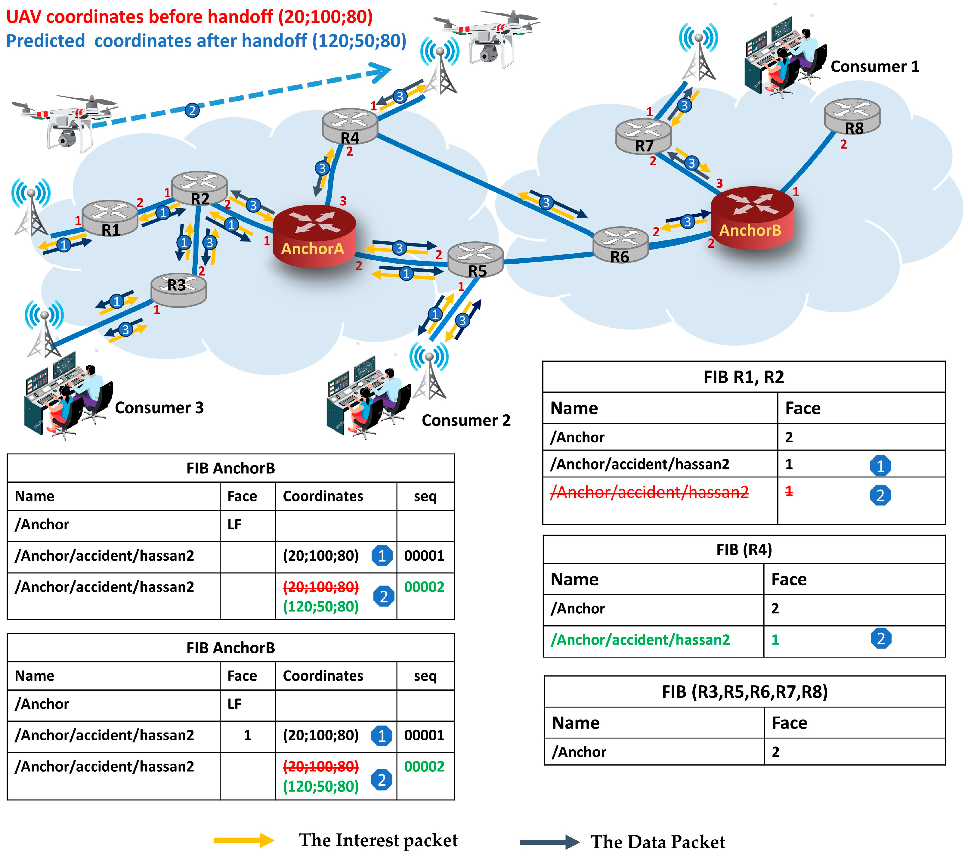
3.2.2. Consumer Interest and Producer Data Packet Forwarding
(1) Consumer Inpt Forwarding: When a consumer wants to request content, it sends an Inpt that typically includes the name of the desired content. In the case of our proposal, the Inpt also includes the X, Y, and Z coordinates, initialized with negative values by default. Upon receiving the Inpt, each intermediate router checks if the Inpt has non-negative coordinates. If so, the router forwards the Inpt using the location-based forwarding strategy. If not, the intermediate router performs a name-based longest prefix match lookup in its FIB to compare the Inpt content’s name with the content names stored in the FIB entries. According to this comparison:
If a match is found for the content name in one of the FIB entries, then the router determines the next-hop interface based on the information stored in the FIB entry, allowing the Inpt to be forwarded directly towards the producer without involving the Anchor. For instance, in
Figure 3, the path of the Inpts of consumer 3 (steps 1) to the producer before handoff is: consumer 3 ⟶ PoA ⟶ R3 ⟶ R2 ⟶R1 ⟶ PoA ⟶ producer.
If no matching is found for the content name in the FIB entries, in this case, the longest matching prefix will be the prefix of the Anchor, and the Inpt will then be forwarded toward the nearest Anchor using the appropriate interface (e.g., Inpts of consumer 2 (steps 1 and 3) in
Figure 3). When the Anchor receives the consumer’s Inpt, it checks its FIB entry associated with the producer’s data name. This entry contains two important pieces of information: (1) producer’s location: this includes the X, Y, and Z coordinates of the producer retrieved previously through the CP or the predicted location coordinates after handoff updated by the RP packets; (2) Outgoing Interfaces: this information specifies the interfaces through which the consumer’s Inpt should be forwarded. If an Outgoing Interface is found, meaning that the path between the MP and Anchor has been created before the reception of the Inpt, then the Anchor and all intermediate routers along the path use the appropriate interface. If no Outgoing Interface is found, the location-based forwarding strategy is used to determine the appropriate interface. In this case, the X, Y, and Z of the Inpt coordinates are updated with the producer’s location coordinates stored in the FIB entry, and each intermediate router along the path between the Anchor and the MP uses the location-based forwarding strategy to select the next Face to forward this Inpt (e.g., in
Figure 4, the path of the Inpts of consumer 1 to the producer after AnchorB is AnchorB ⟶ R6 ⟶ R4 ⟶ PoA ⟶ producer). The forwarding process of the consumer’s Inpt is detailed in Algorithm 1.
(2) Producer data packet forwarding: when the producer receives the consumer’s Inpt, it responds by sending a Data packet that follows the same path as the Inpt in reverse. Each intermediate router along the path uses the information stored in its PIT to forward the Data packet back to the consumer. Additionally, to reduce the computational burden of calculating distances for every Inpt in location-based forwarding, each intermediate router along the path between the producer and the Anchor creates a FIB entry upon receiving the producer Data packet. This FIB entry includes the name of the MP’s data and the incoming Face from which the Data packet was received (e.g., in step 3, a FIB entry for the producer’s content name is added to R4 after handoff, shown in
Figure 4). By doing so, the router establishes a path toward the producer for future consumer Interest forwarding without relying on the involvement of the Anchor, particularly, in the worst-case scenarios, where the path between the MP and consumer is stretched to the Anchor. The forwarding process of the Data packet is detailed in Algorithm 2.
| Algorithm 1 Consumer_InterestForward(Interest I, incomingface F) |
1: Regular CS and PIT lookup
2: if this.IsAnchor then
3: Entry FIB.GetMatchedPrefix (I.name)
4: if Entry ø and Entry. HasFace then
5: SendToNeighbor(I, )
6: else
7: AddcoordinateToInterest (I)
8: for in Neighbors do
9:
10: end for
11:
12: SendToNeighbor (
13: else
14: if I. HaspositifCoordinates and I.IsNoteCreate_Nor_RemovePath then
15: for in Neighbors do
16: if Entry ø and I. HasNegatifCoordinates then
17:
18: end for
19:
20: SendToNeighbor (
20: else
21: Entry FIB.LongestPrefixMatch(I.name)
22: for in Entry. NextHop do
23: SendToNeighbor(I, )
24: end for
25: return |
| Algorithm 2 OnIncomingData (Data D, Incomingface F) |
1: CheckValidity()
2: Interestpackets=PitEntry.getInterests (D.name)
3: if Interestpackets ø then
4: for in Interestpackets do
5: if . HaspositifCoordinates () then
6: FIB.addentry(D.name,F)
7: InterestIncomingFace=PitEntry. getInRecords(
8: // go to outgoing Data pipeline
9: OnOutgoingData(data, InterestIncomingFace)
10: end for
11: return |
3.3. Producer Location Prediction
The prior knowledge of the producer’s new PoA coordinates plays a crucial role in ensuring seamless mobility. As part of our approach, we propose utilizing the producer’s predicted coordinates of the next location where the MP will be present when the handoff is complete as destination coordinates to receive the consumer’s Inpt. These predicted coordinates represent the nearest location to the producer’s new PoA.
When a producer moves out of the range of its current PoA and needs to establish a connection with a different PoA, its network interface continuously monitors the RSS in the current channel. The RSS continues to degrade as the producer moves further away from the current PoA. In our strategy, when the RSS drops below a predefined threshold, the producer predicts the future position coordinates at the time , representing the time required to complete the handoff process. Subsequently, the producer sends the RP packet, which includes the producer’s predicted coordinates, to notify the Anchor.
Several methods have been proposed to predict the future location of a UAV. These prediction methods aim to estimate the UAV’s position at a future time based on its current location and other relevant factors. Common approaches include trajectory extrapolation [
34], sensor fusion [
35], Kalman filtering [
36], machine learning [
37], and dynamic models [
38]. In this paper, a Kalman Filter (KF) [
39] method is used with the aid of Global Positioning System (GPS) and Inertial Measurement Unit (IMU) sensor technologies for predicting the UAV’s future position coordinate.
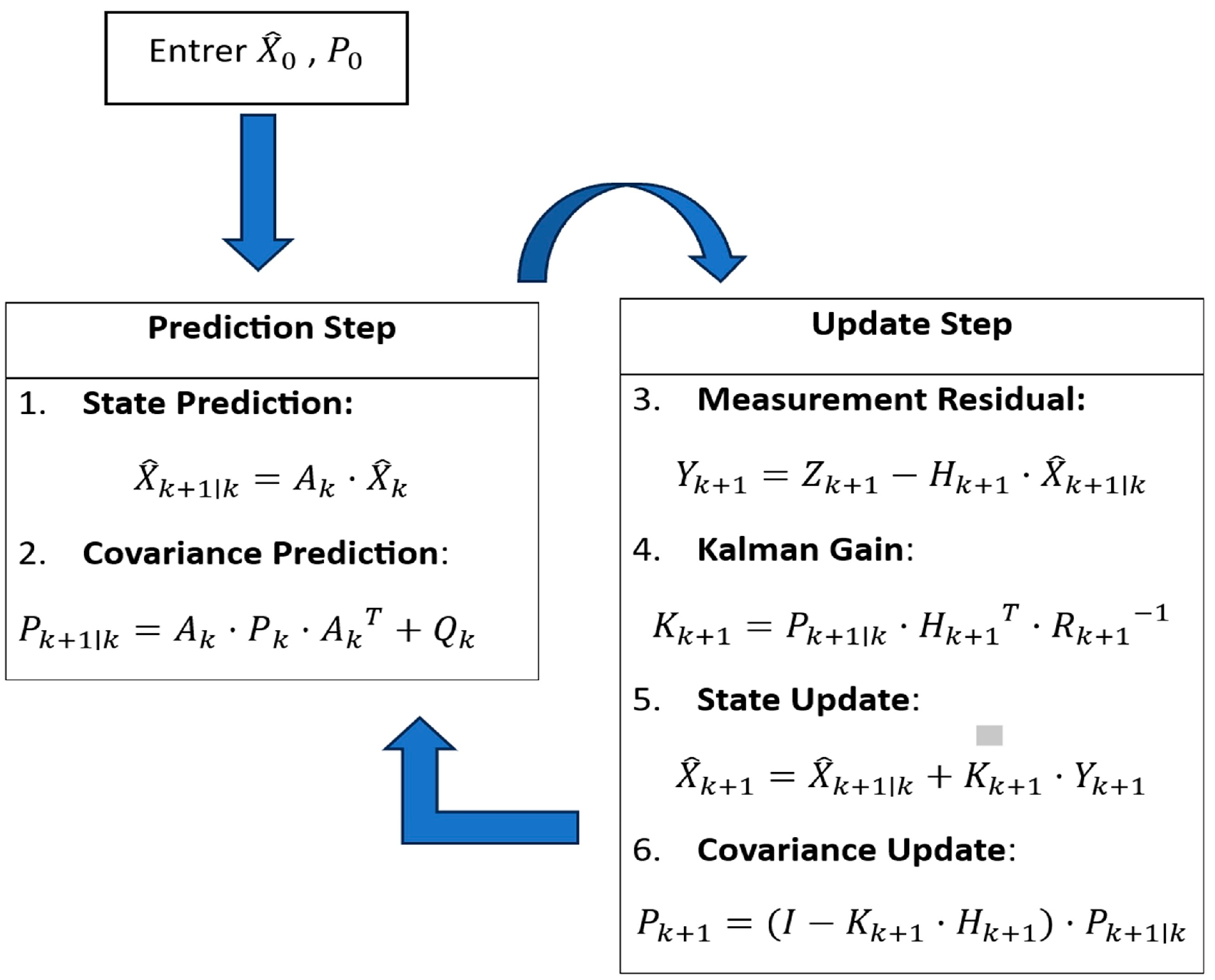
The KF method is a popular method for predicting the future location of UAVs. It is a recursive algorithm that uses a state space model to estimate the UAV’s current state and predict its future state based on the previous state and new measurements. This makes it more robust to noise and disturbances than other prediction methods, such as trajectory extrapolation. The KF operates through a two-step process: prediction step and update step, as shown in
Figure 4. In the prediction step, the KF leverages the state transition model and current state (position and velocity) to predict the UAV’s state (position) at the next time step. This prediction is associated with an uncertainty represented by the error covariance matrix. In the update step, the predicted state is compared with the actual measurements (obtained from a real-time GPS and IMU sensors) to compute the measurement residual. The filter then adjusts the state estimate and error covariance based on this residual and the measurement noise covariance. To predict the position of a UAV using the KF, we need to define the KF’s components as follows:
State vector
The state vector of a UAV at moment k consists of its position and velocity, therefore,
is a vector of 6 × 1.
where
are the estimated position coordinates and
are the estimated velocities along the
x-axis,
y-axis, and
z-axis, respectively.
State transition matrix (A)
Since the position of the UAV changes over time from one time step to the next step, the new coordinate in the next time step can be approximated by Equation (2).
The state transition matrix is typically defined as follows:
Δt represents the time interval between two consecutive time steps k and k + 1.
Measurement matrix
The measurement vector is a 3 × 1 vector representing the position measurements () obtained from a real-time GPS sensor. Consequently, the measurement matrix
is a 3 × 6 matrix that maps the state vector
to a 3-dimensional measurement vector
. It is typically defined as follows:
The initial covariance matrix P0
The initial covariance matrix
is a critical component of the KF, it represents the uncertainty in the initial state estimate. In the context of our case, where the initial state estimate is acquired from GPS and IMU sensors with high accuracy, the diagonal elements of
are usually assigned small values, indicative of a high level of confidence in these estimates. Simultaneously, the off-diagonal elements are set to zero, assuming that the initial errors in different state variables are uncorrelated. The initial values for
matrices are defined as follows:
The initial values for the process noise covariance
Q and the measurement noise covariance
R matrices are determined as follows:
UAV Mobility Model
The movement of UAVs differs significantly from that of common mobile vehicles, owing to their exposure to diverse external factors, including wind speed, turbulence, and environmental conditions. To accurately represent real-world UAV movements, the mobility model must reasonably emulate UAV movement. For that purpose, we propose to use the Gauss–Markov (GM) mobility model [
40] as it closely emulates the uncertain and dynamic nature of real-world UAV movements by introducing randomness into the UAV’s motion. In the GM mobility model, the UAV’s velocity and direction are updated at fixed intervals of time based on their previous values using Gaussian Equation (3). The model employs average velocity, direction, and Gaussian random noise to introduce randomness and emulate the uncertain nature of UAV motion. The degree of dependency on past velocity and direction is controlled by a tuning parameter α, which affects the persistence and smoothness of the UAV’s trajectory. A higher value of α indicates a stronger dependence on past values, leading to more persistent movement patterns, while a lower value results in a more dynamic and rapidly changing trajectory. In the GM mobility model, the cycle of updates for the UAV’s velocity and direction is repeated throughout the simulation. The new values for these parameters are calculated as follows:
where α is the tuning parameter,
and
are the mean of velocity and direction, while
and
are random variables from a Gaussian distribution that give some randomness to the new velocity and direction parameters.
The parameters of the Gauss–Markov model for our scenarios are listed in
Table 2.
4. Evaluation
This section presents the performance evaluation of the DMMS. A comparative analysis is conducted with two popular schemes from the literature: MAP-ME (representing an Anchor-less proposal) and Kite with multiple rendezvous servers, denoted as multi-RV KITE (representing an Anchor-based proposal), which are designed to address the challenges of real-time content delivery in mobile network environments. We have faithfully reproduced the source code of MAP-ME and multi-RV KITE to establish reliable benchmarks. To emulate the named data networking environment, we employ the ndnSIM [
41] simulator, an open-source NS-3-based simulator widely adopted for named data network research.
We implemented the clustering algorithm using Python libraries. The resulting placements of Anchors are provided as input to our scenario for the DMMS and for the multi-RV KITE solution. It is worth noting that the author of the Kite solution did not provide explicit details regarding the method used for selecting the placements of rendezvous servers.
Subsequent sections provide detailed insights into the simulation environment configuration, the selection of performance metrics for evaluating both consumer experience and network cost, and an extensive discussion of the obtained results. A summarized overview of the simulation parameters can be found in the accompanying
Table 2.
4.1. Simulation Setup
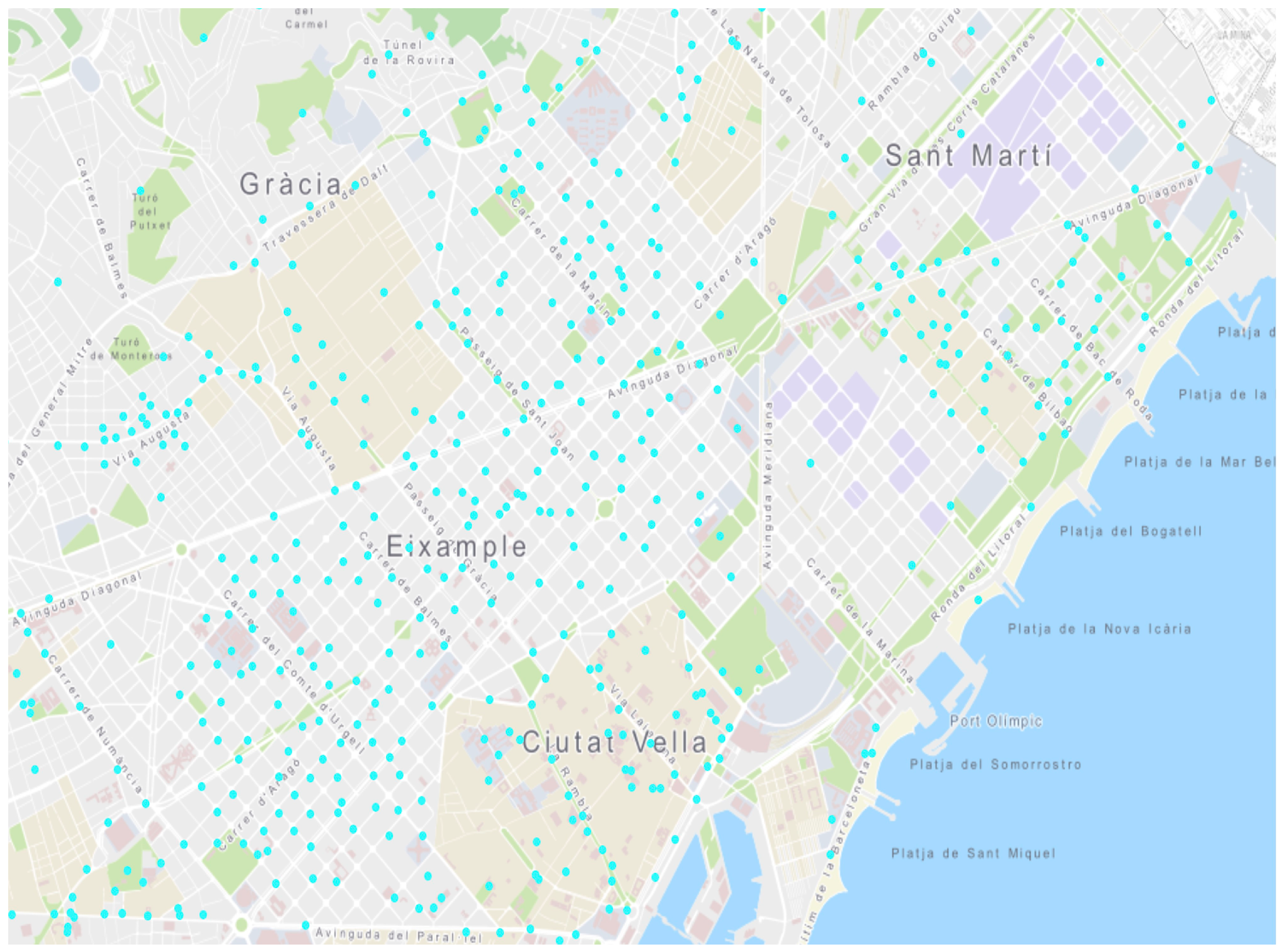
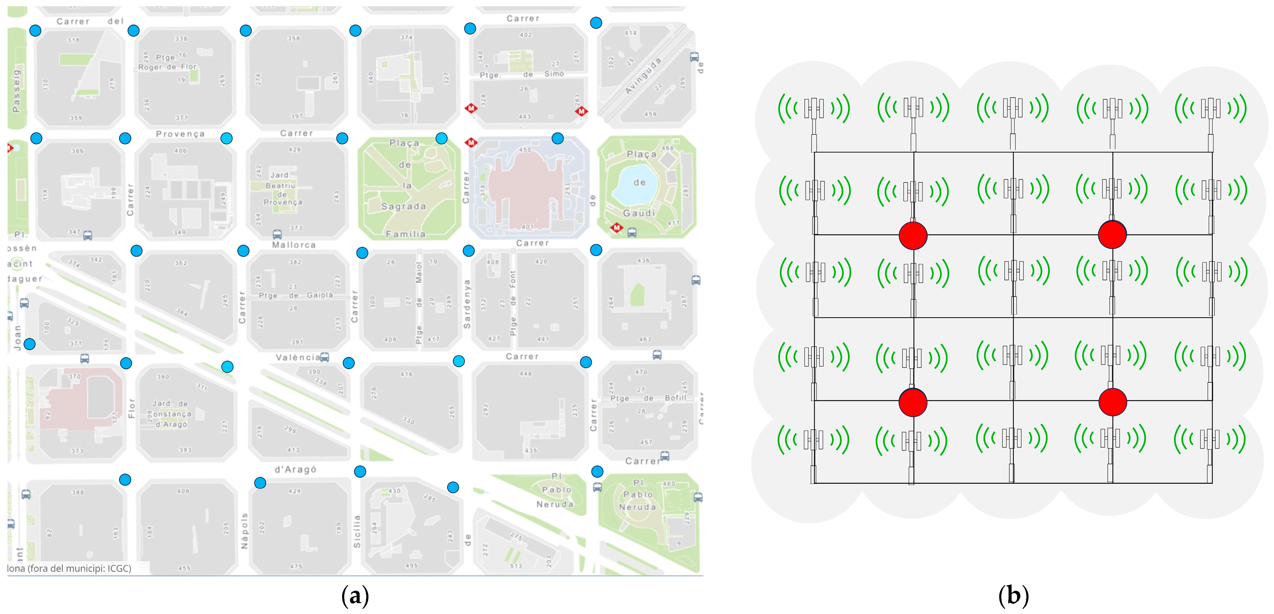
In order to evaluate the efficiency of the DMMS, we have employed a real-world topology to provide a rigorous assessment. Specifically, we have chosen to adopt a Wireless Mesh Network (WMN) installation scenario located within the city of Barcelona [
42], as visually depicted in
Figure 5. Within this context, our scenario was limited to 25 Access points as shown in
Figure 6a within a 5 × 5 grid topology where each distinct grid cell dimension measures 100 × 100 m with one Access point, as shown in
Figure 6b. All Access points operate in the 2.4 GHz radio frequency range and use the IEEE 802.11n access network. Notably, each grid node acts as both an Access point and router to enhance the mesh network’s operational capabilities. In terms of wireless propagation, the channel models used combine the constant speed propagation delay model and the log-distance path loss model.
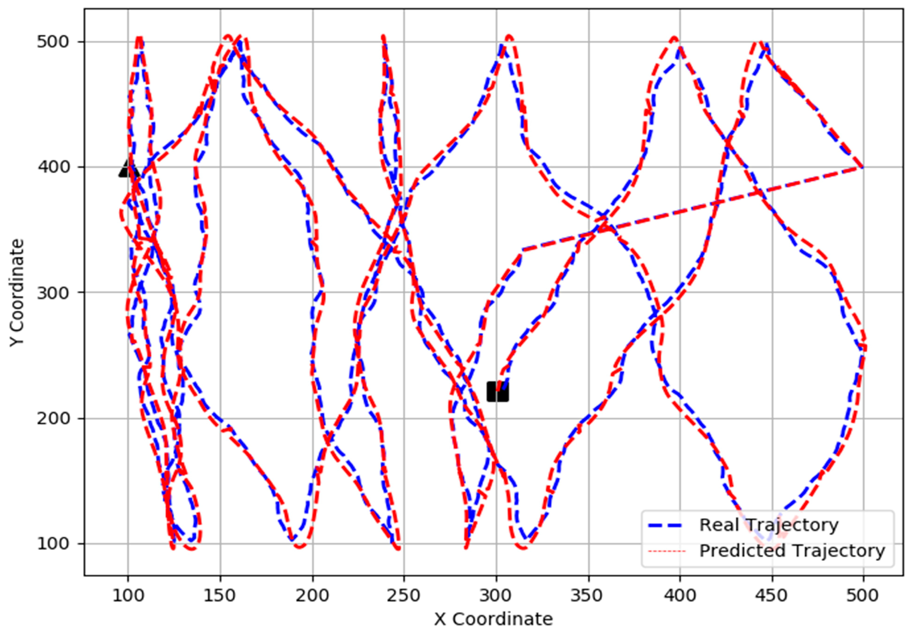
In our scenario, we have on MP and one stationary consumer, with producer equipped with a streaming video application. Consumer continuously sends requests for data to an MP for 100 s with a frequency of five Inpts per second using a Constant Bit Rate (CBR) consumer application. Based on the clustering algorithm, Nodes 6, 8, 16, and 18 are designated as Anchors for the DMMS and rendezvous servers for multi-RV KITE. We set a 100 ms delay for updating the producer’s coordinates (attachment information) on all Anchors in the DMMS and RVs in multi-RV KITE. The MP moves freely within the grid topology according to the GM mobility model, where it changes its velocity and direction in each epoch based on previous movements to emulate the flight pattern of a real-world UAV. We conducted 100 runs for each MP speed, with the MP’s movement speed ranging from 1 m per second to 30 m per second. We implemented the KF algorithm using C++ for the producer’s coordinate location prediction. The next location coordinate is predicted every ΔT = 500 ms using the same parameters as described in the previous section.
Figure 7 shows the true trajectory of the MP at a speed of 30 m/s in blue and the estimated trajectory using the Kalman filter in red. The rectangle and triangle represent the start and end positions of the producer, respectively.
To assess the performance of the location prediction model, we use the Root Mean Square Error (RMSE), a widely used metric for measuring the average magnitude of errors between predicted positions and actual positions. RMSE values are non-negative, with smaller values indicating better prediction accuracy.
The formula for calculating RMSE is typically:
where
represents the predicted coordinates,
represents the real coordinates, and
N is the total number of predictions.
Table 3 presents the average RMSE value of the KF model, averaged over all 100 runs for each producer speed. The KF model demonstrates accurate tracking of the producer’s position. However, the RMSE value increases with the producer’s speed. This is attributed to the KF’s reliance on predicting the future state based on the current state. As the producer’s speed rises, predicting its future position becomes more challenging due to rapid changes in location, leading to accumulated prediction errors and higher RMSE. It is noteworthy that the RMSE value of the KF is influenced by the noise in the measurements. Higher levels of measurement noise can result in an elevated RMSE value.
4.2. Results and Discussion
In the subsequent section, we discuss the simulation results, focusing on the consumer Quality of Service (QoS) evaluated through four key performance indicators: average Inpt loss, average Data packet delay, average path stretch, and handoff latency. Additionally, we explore the network cost to support producer mobility in the DMMS, which is evaluated using signaling overhead performance. Furthermore, we also study how the number of Anchors in the network impacts the consumer QoS. In addition, we discuss the limitations of our strategy that can be explored for further research.
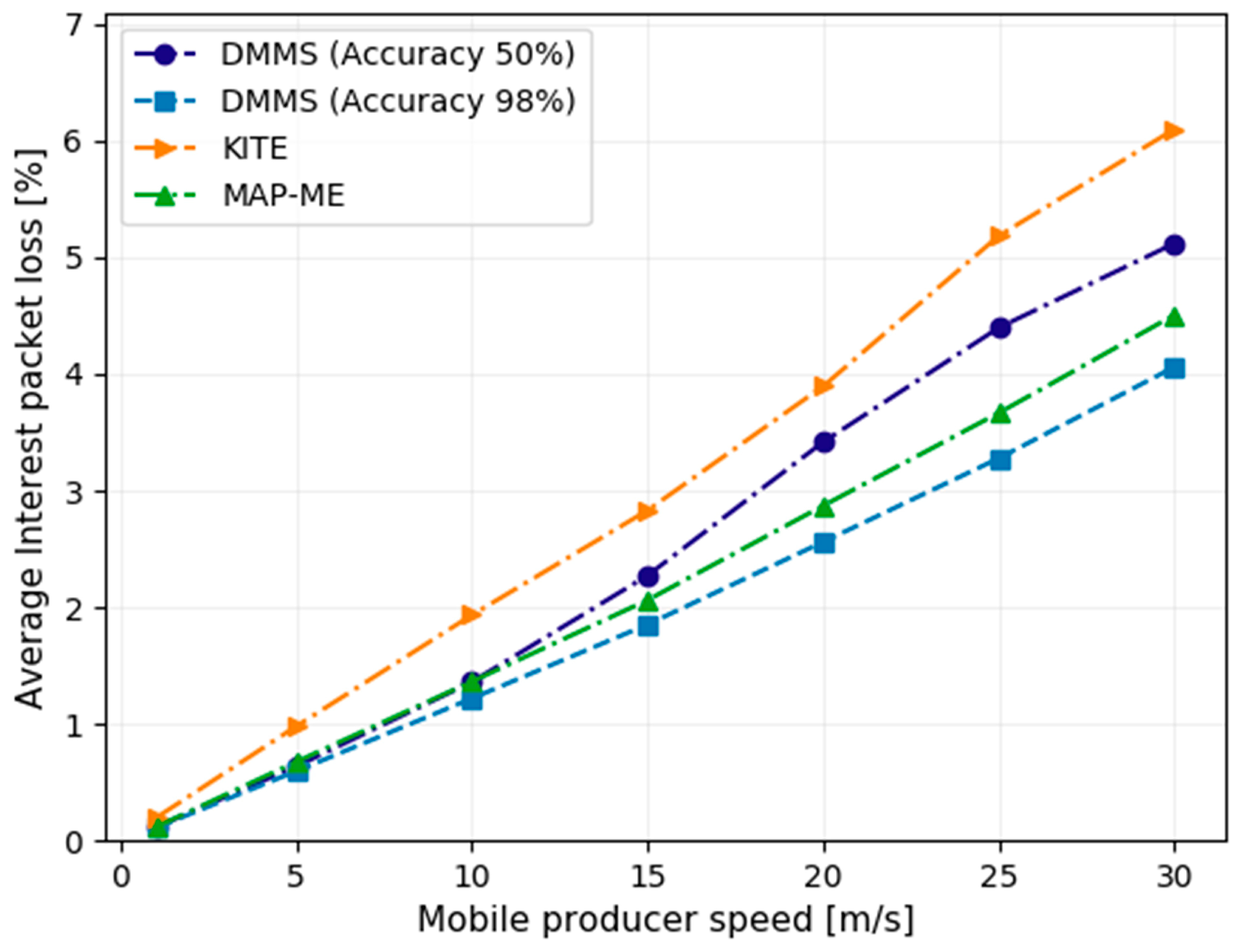
4.2.1. Interest Packet Loss
Interest packet loss is an important criterion in mobility management schemes in NDN, especially for low-latency-sensitive applications that require a negligible packet loss during the handoff to ensure that data remain relevant and useful. The Inpt loss rate is defined as the total number of Inpts sent by all the consumers minus the number of Data packets that arrived over the total number of Inpts sent.
Figure 8 presents a comparison of the average packet loss rates of different mobility support schemes; the
y-axis represents the average packet loss rates, while the
x-axis represents the speed of the mobile producer (ranging from 1 m/s to 30 m/s). As a first observation, we notice that with the increase in the producer’s speed, there is a corresponding rise in Inpt loss due to increased handoff events. Nevertheless, the result shows that the multi-RV KITE scheme has the highest packet loss rate. This is because the producer receives consumers’ Inpts after TI/TD messages are exchanged to establish a new trace path, which means that the Inpts received at the time of trace path creation will be considered lost. Furthermore, multi-RV KITE suffers from the stale path problem caused by frequent handoffs that occur when the producer moves to a new PoA, and the old trace path may stay active. The DMMS and MAP-ME achieve similar packet loss rates at producer mobility speeds below 5 m/s. However, in high-speed mobility scenarios, the DMMS with high producer’s location prediction accuracy exhibits significantly lower packet loss than both multi-RV KITE and MAP-ME. Even with low prediction accuracy, the DMMS maintains an acceptable packet loss ratio.
In comparison to MAP-ME, DMMS reduces the packet loss rate by approximately 10%, and when compared to multi-RV KITE, the reduction is even more significant, at 20%. This result is attributed to the proactive mobility management that notifies the Anchor about the predicted location of the producer when handoff happens. Consequently, Inpts are redirected proactively toward the producer’s new PoA.
4.2.2. Path Stretch
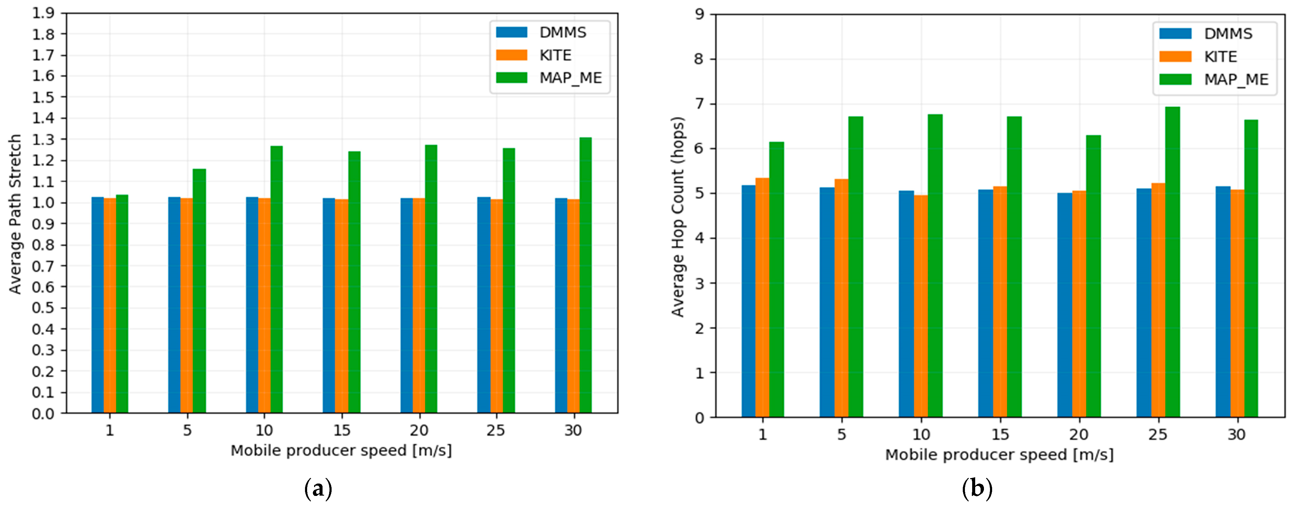
The path stretch metric represents the ratio of the actual forwarding path length, measured in terms of the number of hops, to the shortest possible path length between the consumer and the producer. The average hop count metric represents the average number of intermediate hops a Data packet travels from its source (producer) to its destination (consumer). Path stretch can directly impact the delay or latency experienced by Data packets as they traverse the network. When the stretch is close to 1 (i.e., the actual path is almost as short as the shortest path), Data packets reach their consumer faster, resulting in lower delay. However, if the path stretch is significantly higher, Data packets may take longer to reach their destination, leading to increased delay. An efficient mobility management strategy should ensure that the MP remains reachable using a path with minimal extension.
Figure 9a,b, respectively, show the average path stretch and the hop count as a function of the producer’s movement speed. As main observations, we notice that the slopes of the three schemes in the figures are not impacted much by the producer’s mobility speed. We further notice that MAP-ME achieved the highest path stretch and average hop count among the three schemes; this is attributed to one of the drawbacks of the MAP-ME scheme, which tends to create a triangular path when the MP changes the PoA, as the producer sends an updated Inpt from the new PoA towards the old one to maintain a seamless producer mobility management. In contrast, the the DMMS achieves a minimal path stretch about 10% longer than the shortest possible paths, as shown in
Figure 9a, and the average hop counts are 46% lower than those of the MAP-ME scheme, as shown in
Figure 9b. This result is expected because of the strategic placement of Anchors within the network. By effectively positioning these Anchors at minimal distances from all nodes in the network, the additional distance traveled by packets through the Anchor remains relatively insignificant. Secondly, the location-forwarding strategy ensures that the Inpts are forwarded along the shortest path between the Anchor and the producer. It is worth noting that the multi-RV KITE scheme also has a lower path stretch due to its benefiting from rendezvous server placements, which reduces the path between the producer and consumers through the rendezvous servers.
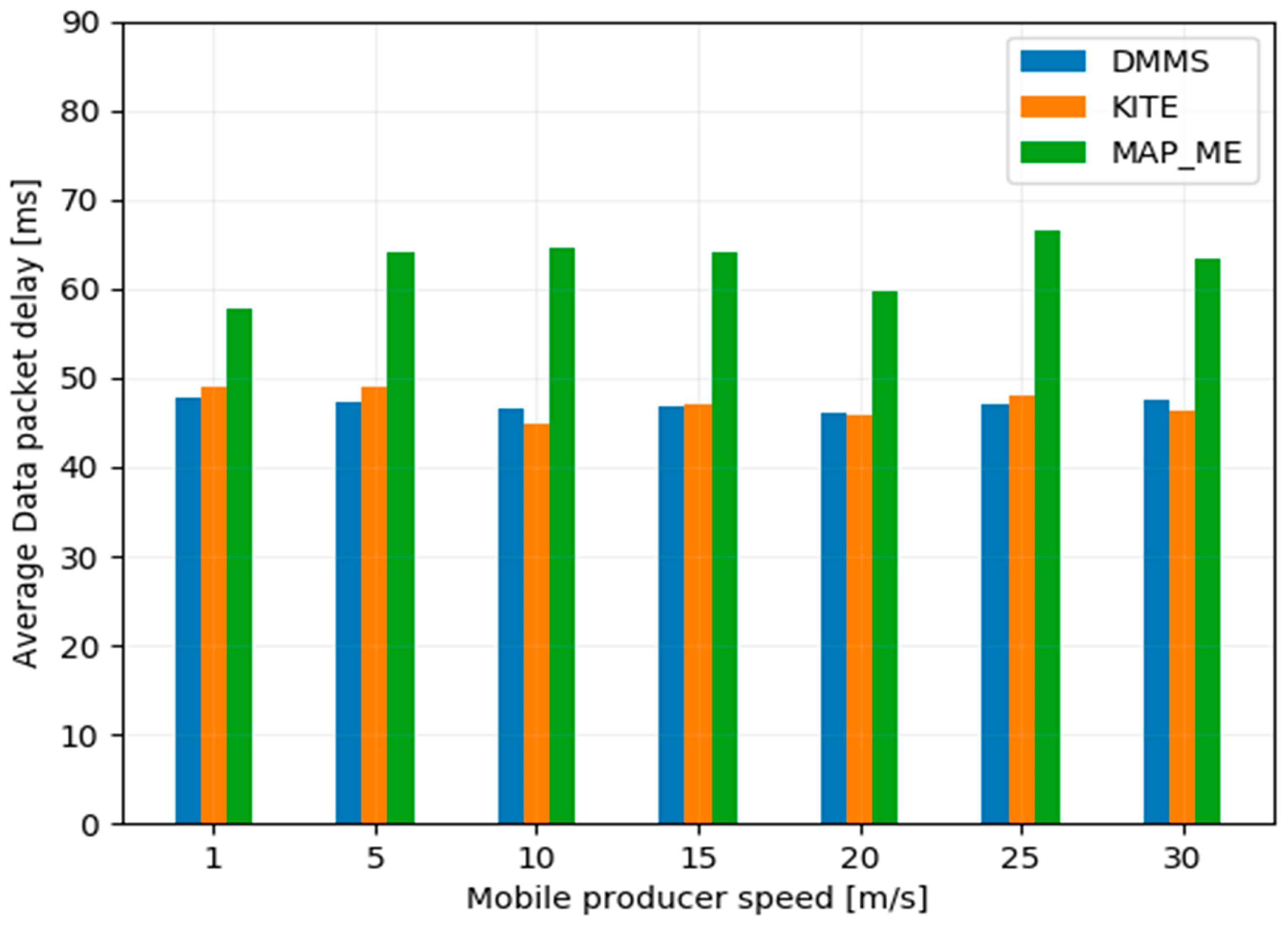
4.2.3. Data Packet Delay
To meet the low-delay requirements of latency-sensitive applications, a suitable mobility management scheme must ensure that data can be delivered quickly and with minimal delays. The Data packet delay refers to the time it takes for a consumer to successfully receive a requested Data packet after expressing an Inpt, including the time of Inpt retransmissions. The average Data packet delay is calculated by dividing the sum of delays for each Interest–Data pair by the total number of received Data packets.
Figure 10 demonstrates the average Data packet delay (represented on the vertical
y-axis) as a function of the producer’s movement speed (depicted on the horizontal
x-axis). We can see that the DMMS and multi-RV KITE achieved a slightly lower Data packet retrieval delay. In contrast, MAP-ME achieved the highest delay among the three schemes due to the significant effect of path stretching associated with each handoff event.
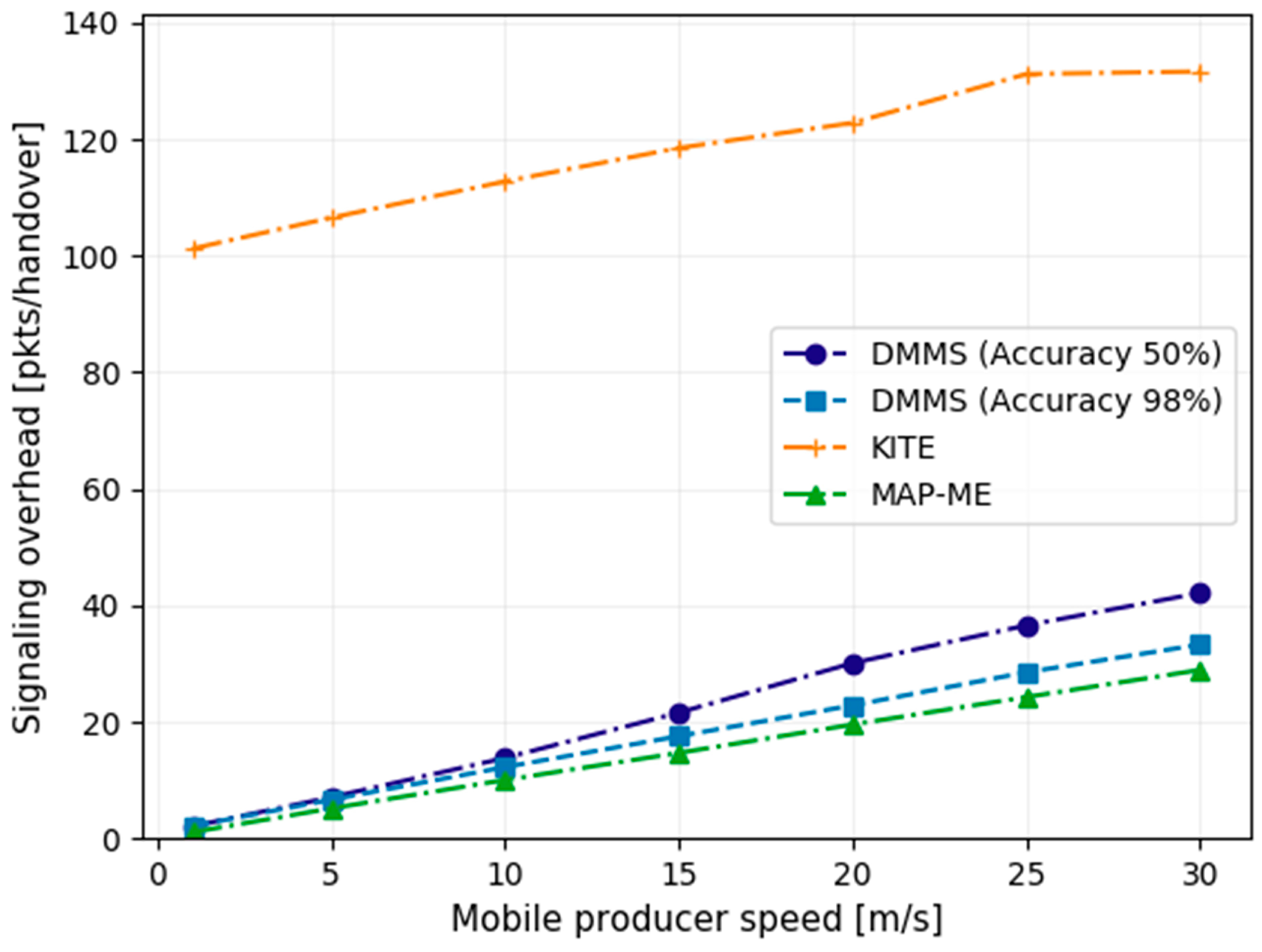
4.2.4. Signaling Overhead
Signaling overhead is an important aspect to consider when designing a mobility support scheme. There is a tradeoff between signaling overhead and user experience. In fact, minimizing signaling messages can help reduce network congestion and conserve resources, leading to a more efficient use of the network infrastructure. On the other hand, increasing signaling messages for frequent updates on the network’s condition can enhance user experience by maintaining a consistent quality of service. This tradeoff is a fundamental challenge in designing a mobility support scheme that provides a high-quality user experience while efficiently minimizing unnecessary signaling traffic. Signaling overhead is defined as the number of packets needed to ensure that the consumer’s Inpt can reach the MP when handoff occurs. We compared the signaling overhead generated by the three schemes while varying the producer speed, as shown in
Figure 11. Multi-RV KITE generates a higher signaling overhead compared to MAP-ME and DMMS. This is because of the periodic sending (every 2 s) of TI/TD packets to refresh the trace path between producer and rendezvous servers. In contrast, both the DMMS and MAP-ME schemes generate considerably less signaling overhead. The DMMS uses at least one Inpt packet to remove the old path, notify the Anchors about the handoff event, and inform Anchors about the predicted location of the MP after a handoff. Meanwhile, MAP-ME uses a single Inpt packet to update the path between the new and old producer’s PoA.
It is worth noting that DMMS is affected by the prediction accuracy of the producer’s next location, causing an additional signaling overhead.
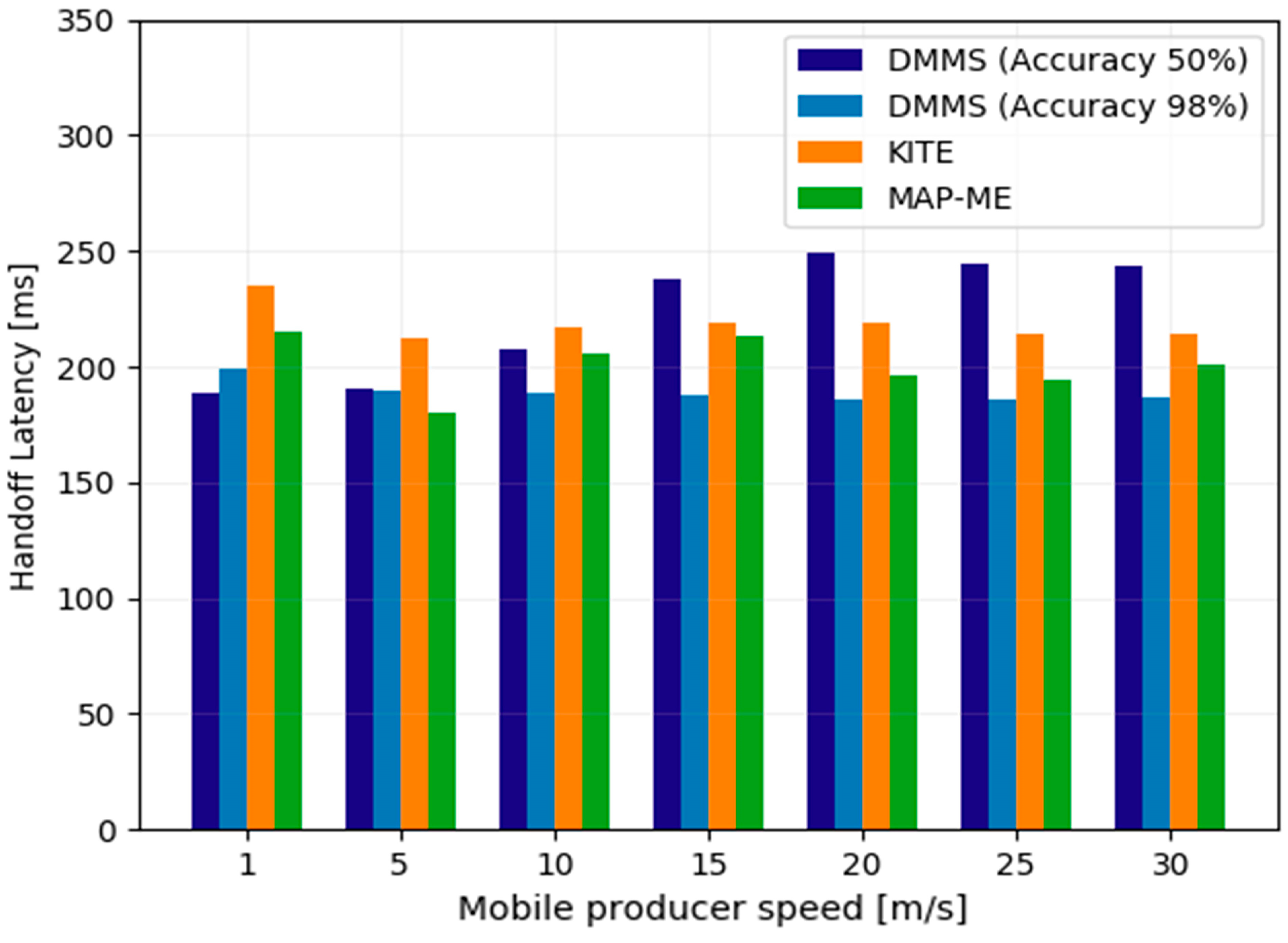
4.2.5. Handoff Latency
Handoff latency is defined as the period between the time when the MP loses the connection with its current PoA and the time when the MP receives the first Inpt from the new PoA. Handoff latency comprises two types of latency: (i) layer 2 latency: this delay represents the time required to complete the handoff, which is set at 100 ms in our scenario; (ii) mobility management latency: this delay is defined as the time required for the MP receive the Inpt after the handoff is completed.
Figure 12 shows the handoff latency measured in milliseconds for the MAP-ME, multi-RV KITE, and DMMS schemes against the producer speed. As we can see, the highest handoff latency was for the multi-RV KITE scheme. This increase in latency was primarily attributed to the mobility management delay resulting from the exchange of TI/TD messages between the MP and the RV server, which is necessary for creating the trace path, in addition to the time required to update the MP’s information on all RV servers. MAP-ME, on the other hand, achieved a lower handoff latency, where the Inpt only needs to wait for the update of the intermediate routers and reach the old PoA, which is nearly in close proximity to the new PoA in our scenario. Therefore, the handoff latency in MAP-ME is dependent on the distance between the old PoA and the new PoA.
The DMMS with high producer’s location prediction accuracy achieves the lowest handoff latency thanks to its proactive mechanism, which informs the Anchor about the expected location of the MP as soon as the handoff process is initiated. In other words, the DMMS reduces the handoff latency by overlapping the mobility management latency with link-layer latency, providing the quickest response to the producer’s handoff event.
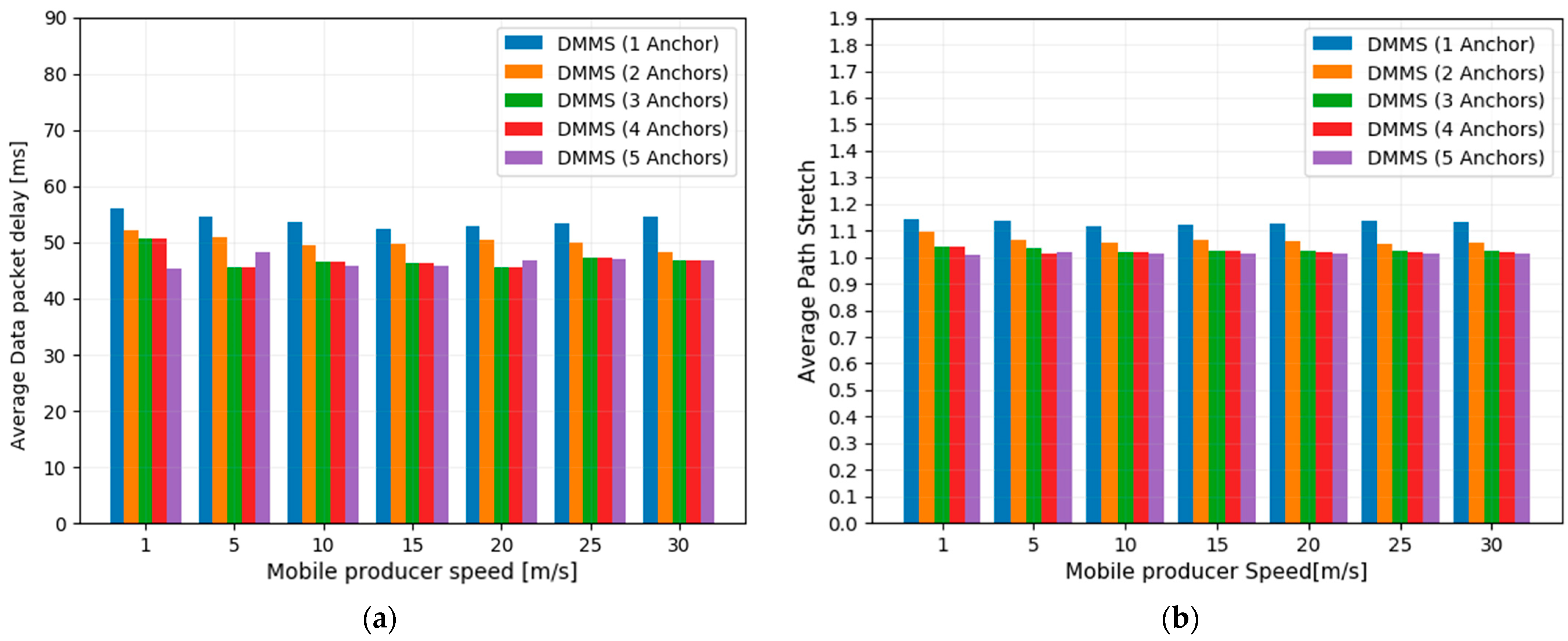
4.2.6. The Impact of the Number of Anchors on Consumer QoS
To quantify the impact of the number of Anchors on our proposed strategy’s performance, we particularly focus on two metrics impacted by the Anchor-based approach: the path stretches and Data packet retrieval delay. We tested these metrics across varying the number of Anchors from one to five using the K-Medoids-based Anchor placement algorithm.
Figure 13 depicts the path stretch and the average Data packet retrieval delay of the DMMS as a function of the MP speed using a number of Anchors varying from one to five. As the main observations, we notice that the number of Anchors significantly affects both path stretch and Data packet retrieval delay. Increasing the number of Anchors from
N = 1 to
N = 4 resulted in a 10% reduction in path stretch and a 16% reduction in delay. This is because an increasing number of Anchors leads to smaller clusters formed in the network, which decreases the distance between the consumer, producer, and Anchor. Consequently, it mitigates path stretch, especially in the worst scenarios where the consumer and producer are located in the same cluster and the path between them is stretched to the Anchor. We also observed that adding more than four Anchors in our scenario did not result in any additional reduction in either path stretch or Data packet retrieval delay. This is expected because increasing the number of Anchors results in shorter distances between Anchors. However, the clusters formed will become increasingly small, leading to the creation of clusters with few routers with no additional impact.
4.2.7. Limitations of the Proposed Approach
Our strategy has three main limitations. First, to support producer mobility we use the location-based forwarding strategy to fill the gap resulting from the lack of the information on the producer’s new location after handoff. However, location-based forwarding cannot guarantee 100% delivery in mobile and ad hoc networks due to the local minimum issue. In a connected graph, a local minimum occurs when a node, denoted as x, is closer to the destination y than any of its neighbors, even though y is not directly connected to x. In this situation, the node x faces difficulty in deciding the next hop, resulting in a failure in the forwarding process. Second, the effectiveness of location prediction depends on the accuracy of the prediction algorithm and the quality of the input data. If the predictions are not accurate, it may result in inefficient forwarding decisions, leading to increased latency and packet loss. Third, the limitation arising from the overhead generated by the synchronization of producer location coordinates among Anchors during frequent handoffs of producers poses a significant challenge. As producers move in the network with high speed, the necessity to synchronize data introduces a notable overhead, impacting the system’s performance and efficiency. The continuous synchronization process consumes communication and processing resources, leading to increased network congestion, latency, and potential resource contention among Anchors.
5. Conclusions
In this paper, we propose a distributed mobility management scheme in NDN designed to support producer mobility and ensure low-latency content delivery for UAVs as a use case. Our scheme is based on three components: (1) a new forwarding approach that combines default and location-based forwarding strategies; (2) a location prediction strategy to predict the location of the MP prior to handoff; (3) distributed Anchors that proactively track and forward the consumer Interest packets toward the MP when handoff events occur. Through simulation, we evaluated the performance of the proposed strategy using a real scenario and compared it with two popular schemes, which represent both Anchor-less and Anchor-based approaches. The results obtained showed that the proposed scheme can effectively minimize communication delay and Inpt loss with low overhead signaling under producer mobility. These promising results make the proposed strategy the best-suited producer mobility management for seamless data delivery.
Our future work includes: (1) further improving the distribution of Anchors by finding the optimal number and optimal placements of Anchors able to handle the network traffic; (2) improving the prediction accuracy by leveraging deep learning techniques by focusing on the producer mobility’s related features, which we expect to present even better prediction results; and (3) conducting further experiments for different network topologies and environments.


