1. Introduction
With the continuous advancement of multimedia technology, the volume of traffic generated by multimedia applications, such as online meetings and live video broadcasts, has been increasing steadily [
1,
2,
3]. Multicast is a data transmission method that transmits packets along a distribution tree from data sources to a set of receivers by simply replicating the packets at branches of the multicast distribution tree [
4,
5,
6]. Thus, multicast can effectively save network resources and improve bandwidth utilization. Multicast technology can be divided into network layer multicast, application layer multicast, and link layer multicast. Compared with the other two technologies, network layer multicast has greater scalability, as it has the ability to effectively avoid redundant data transmission and cover a wider network range. As a result, network-layer multicast has always been an important research topic.
According to Cisco’s annual internet report [
7], the number of devices connected to the internet worldwide is expected to increase by 50% from 2018 to 2023. With the growth in the number of network devices, the number of multicast groups on the network is also expected to increase. In multicast technology, the multicast capacity, which refers to the number of multicast groups that the network can accommodate, is a very important indicator. The multicast capacity signifies the throughput and efficiency of the network, and is an important measure of the scalability of multicast technology. The selection method of multicast joining nodes (MJNs) has a significant influence on multicast capacity. When joining a multicast group, a group member first sends a request to a designated router (DR). Then, the DR selects a node in the existing multicast tree (known as a multicast joining node, or MJN) to establish a multicast distribution path from the MJN to itself. The MJN selection method running on the DR has a significant impact on the distribution of the multicast tree, which directly affects the load distribution in the network, and thus has a considerable impact on multicast capacity [
8,
9,
10].
The main challenge faced by MJN selection methods is how to effectively detect the path load status between MJN and DR, especially in the case of asymmetric routing [
4,
8,
9]. Due to the fact that asymmetric routing has become a common feature of networks, more and more multicast technologies are adopting a downlink multicast path to ensure the quality of multicast data transmission [
1,
11,
12,
13]. The establishment of downlink paths means that the multicast path is the shortest path from MJN to DR, which ensures that data can be transmitted from the multicast tree to the receiver with the shortest delay. In contrast to the downlink path, the uplink path means that the multicast path is the shortest path from DR to MJN, and multicast data will not be transmitted from the multicast tree to the receiver with the shortest delay, leading to a deterioration in the quality of multicast service. In order to establish low-load downlink multicast paths, DR must consider asymmetric routing when detecting multicast path load status, otherwise the load status of the upstream path will be detected, resulting in incorrect detection results. However, few existing MJN selection methods consider this. This defect makes it difficult for existing MJN selection methods to achieve good results in real environments. In addition, MJN selection methods should have low latency and distributed characteristics for practical engineering deployment.
To address this issue, we have designed an MJN selection method based on the reverse shortest path tree (RSPT). During network initialization, the DR constructs an RSPT of K-hop subgraph with itself as the root, that is composed of all shortest paths from other nodes in the subgraph to the DR. As long as the leaf nodes of RSPT send probe messages to the DR, the DR can perceive the load status of all downlink paths and select the MJN with the lowest load to join the multicast tree. Therefore, RSPT can help the DR efficiently establish downlink multicast paths in the case of asymmetric routing. In addition, the RSPT-based MJN selection method is distributed, low-latency, and has the potential for practical engineering deployment.
The main contributions of this paper are:
This article proposes an efficient load detection mechanism for downlink multicast paths. By constructing RSPT, this mechanism enables DR to evaluate the load status of downlink multicast paths efficiently. This mechanism is fully applicable to situations where routing is asymmetric;
We have designed a real-time, distributed MJN selection algorithm that can immediately provide service for new group members, ensuring minimal delay in multicast service. Additionally, this algorithm does not require a central management node to participate in the calculation of multicast paths, which helps improve the scalability of multicast;
Through a large number of experiments, the proposed method has been shown to have a low cost, low latency, and the ability to effectively balance the load state in the network, even the routing is asymmetric.
The structure of this article is organized as follows.
Section 2 presents a review of the related work.
Section 2 introduces the proposed MJN selection method, which consists of two main parts: the construction of RSPT and the implementation of the MJN selection method.
Section 4 describes the experiments conducted to evaluate the proposed method. Finally,
Section 5 concludes the paper. The notations and definitions used in this paper are summarized in
Table 1.
2. Related Work
In this chapter, we focus on traditional IP multicast and existing ICN multicast.
In traditional TCP/IP multicast, WAVE [
13] is an important MJN selection method that influences many multicast mechanisms [
14,
15,
16,
17].
This method requires the DR to first send a request to the root of the multicast tree. When the multicast tree root receives the request, it will forward the request along the multicast tree. Each multicast tree node that receives the request will reply to the DR with a probe message, that will collect the load status information along the way. Upon receiving the probe messages, the DR can understand the load status of the downlink multicast paths, and then select the path with the lowest load to join the multicast tree. This method is essentially a greedy method that selects the path with the lowest load to join the multicast tree each time. It can effectively deal with situations where the routing is asymmetric. However, because it requires probing all of the nodes on the multicast tree, this method can lead to long multicast service delays, heavy network loads, and difficulty in deploying in engineering environments.
In order to meet the deployment requirements in engineering environments, many mature TCP/IP multicast techniques directly select the root node of the multicast tree as the MJN. Among them, some multicast technologies construct source trees, in which the root node of the multicast tree is located at the data source. Therefore, the MJNs of these multicast technologies are data sources, such as PIM-SSM [
18], PIM-DM [
19], MOSPF [
20], etc. There are also some multicast technologies that construct shared trees, in which the root node of the multicast tree is located at the core or Rendezvous Point(RP). Therefore, the MJNs of these multicast technologies are all cores or RPs. These MJN selection methods cannot consider the network load status, which may easily lead to network load congestion and limit the scalability of multicast.
In ICN, routing is based on the content name rather than the IP address. This name-based routing allows receivers to request data from any position on the multicast tree, which is beneficial for optimizing the path of multicast data transmission [
21,
22,
23,
24]. The following is an introduction to some of the MJN selection methods used in ICN multicast technologies.
ILDM [
25] is a multicast technology based on ICN. This technology proposes a path-state-aware MJN selection method. The method requires the control plane to calculate the path from MJN to DR and to detect various load statuses. Upon obtaining the load status of the downlink multicast path, the control plane returns the MJN with the lowest path load to DR. The MJN selection method of ILDM is essentially the same as WAVE, both of which adopt a greedy strategy to select the path with the lowest load to join the multicast tree. The difference is that the path detection of WAVE is distributed, while ILDM utilizes the control plane. ILDM can effectively deal with asymmetric routing issues. However, ILDM is a centralized MJN selection mechanism, that requires the control plane to perform a large amount of calculation, resulting in long multicast service delays and high pressure on the central node.
Classic ICN solutions, such as DONA [
26], CCN [
27], and NDN [
28,
29] inherently support multicast. The multicast mechanism of these solutions aggregates identical data requests by preserving existing data forwarding paths, thus supporting multicast services. When selecting MJN in these multicast solutions, they essentially choose the node closest to the receiver. Data request packets sent by the receiver will be forwarded in the network according to specific rules, and the first node that has the requested data will become the MJN. This method is advantageous in shortening data forwarding paths, but it cannot perceive the network’s load state, which can lead to congestion.
As a famous ICN solution, PURSUIT [
30] also proposes a multicast mechanism. The multicast mechanism in PURSUIT relies on the topology manager (TM). TM in PURSUIT encodes the forwarding path in the Bloom filter of the data packet. When the data packet reaches a forwarding node, the forwarding node only needs to perform an “AND” operation between the label of the outgoing link and the Bloom filter in the data packet. If there is any match, the data packet is forwarded through the corresponding link. Multicast transmission can be achieved by simply encoding the entire multicast tree into a single Bloom filter. This multicast method relies on the central management node TM. However, this method does not take into account the issue of routing asymmetry when calculating multicast trees. Moreover, the centralized calculation method is not conducive to improving multicast scalability.
NOMA [
31] is a multicast communication mechanism designed based on MobilityFirst. NOMA uses Global Name Resolution Service (GNMRS) as a mapping between identifiers and address locators. NOMA first assigns a unique name to each network node; all entities interested in receiving data from a multicast stream can register their unique name in GNMRS. Then, the multicast service manager near the gateway uses this information to construct a multicast tree based on available resources and the desired size of the tree. Then, recursively, the names of each branch router in the multicast tree are mapped to the multicast group identifier in GNMRS. Similar to ILDM, PURSUIT, etc., the construction and maintenance of the multicast tree in NOMA depends on the multicast management node. However, this method does not take into account the issue of routing asymmetry when calculating multicast trees. Moreover, the centralized calculation method is not conducive to improving multicast scalability. At the same time, when the multicast membership changes, this method requires recalculation of the multicast tree, which can have a significant impact on the quality of multicast services.
In addition, there are many methods attempting to construct Steiner trees to the balance network load and improve multicast capacity. These methods include algorithms based on genetic algorithms [
14,
15,
32], taboo search [
33], greedy randomized adaptive search process [
16,
34], simulated annealing [
17,
35], and other ideas. Many of these algorithms also use greedy strategies proposed in WAVE [
14,
15,
16,
17]. However, a common problem with these algorithms is that they rely on centralized computing paradigms and involve a large number of iterative calculations. This can lead to significant service delays and central node performance bottlenecks, which hinder the scalability of multicast. In addition, they have not been able to address the issue of routing asymmetry.
In summary, some of the existing MJN selection methods are unable to consider the asymmetry of routing, such as most TCP/IP multicast protocols; some methods have high multicast processing delays and heavy network loads, such as WAVE; and some methods use a centralized computing paradigm, that is not conducive to improving multicast scalability, such as ILDM, PURSUIT, and NOMA. Therefore, there is a need for an MJN selection method that fully considers the asymmetry of routing, has low latency, and distributed characteristics.
3. Reverse Shortest Path Tree Based MJN Selection Method
Our RSPT-based MJN selection method can be divided into two parts. The first part involves constructing the RSPT, while the second part involves utilizing network load state information collected by RSPT to select the MJN.
3.1. Construction of RSPT
RSPT is composed of the shortest paths from other nodes in the K-hop subgraph to DR. DR can efficiently evaluate the load status of the downlink multicast path using RSPT, even in cases of routing asymmetry. DR can further select the MJN that minimizes the cost of the multicast path to join the multicast tree, reducing network load congestion and improving multicast scalability. Therefore, RSPT is a key component of our proposed method.
The construction of RSPT consists of three main steps: firstly, the construction of a K-hop subgraph, secondly, the collection of information using probe messages, and lastly, the generation of RSPT.
3.1.1. The K-Hop Sub-Graph Construction
DR utilizes RSPT to the detect network load, but it may become overwhelmed when dealing with larger networks. To mitigate this, DR will only construct an RSPT that covers its own K-hop neighbourhood subgraph. During the network initialization phase, DR will broadcast requests with a maximum forwarding distance of K. This ensures that all K-hop neighbours of DR receive the requests. According to the “Six Degrees of Separation” principle, it is possible to connect with anyone within six hops in a social network. Therefore, we limit the value of K to be less than six.
3.1.2. Using Probe Message to Collect Information
Upon receiving a probe request, each node responds with a probe message that is sent to the DR via unicast. The nodes forwarding the probe message add their own load status to it. In large network topologies, the probe messages may contain excessive node information that exceeds the maximum transmission unit (MTU) limit. Therefore, the probe message supports fragmentation. The design of the probe message is illustrated in
Figure 1.
The header of the probe message has the following fields.
Type: This field indicates the type of the message, whether it is a probe message or a request message;
Fragment Tag: This flag indicates whether the message is the last fragment or not. If the message does not have any fragments or is the last one, the flag is set to 1; otherwise, it is set to 0;
Fragment Index: This parameter indicates the index of the current fragment;
Node Cnt: This parameter indicates the maximum number of node information that can be stored in the message;
Node index: This parameter indicates the number of nodes with information that has been recorded in the message;
(IM ID-load status): Each intermediate node’s information is stored as a key-value pair, with the ID of the node as the key and its load status as the value.
3.1.3. The Generation of RSPT
To reduce the number of probe messages, we construct a reverse shortest path tree(RSPT) with the DR as the root. Once DR establishes RSPT, DR can know all of the leaf nodes. Then, DR will periodically send probe requests to the leaf nodes. When nodes receive the probe request, they will know that they are the leaf nodes of the RSPT, and then reply to the DR with probe messages.
When the DR receives a probe message, it can extract a node sequence from it. The DR then checks whether is included in the existing RSPT C. If is included in C, it is discarded. Otherwise, is added to C, and any sequence in C that is contained by is removed. C is a set of sequences, where C, including , means that is a subsequence of any sequence in C.
Once the DR receives the probe messages of all nodes, the first node of all sequences in
C are leaf nodes in the reverse path tree. The algorithm is shown in Algorithm 1.
| Algorithm 1: The RSPT Generation Algorithm. |
|
3.1.4. An Example of RSPT
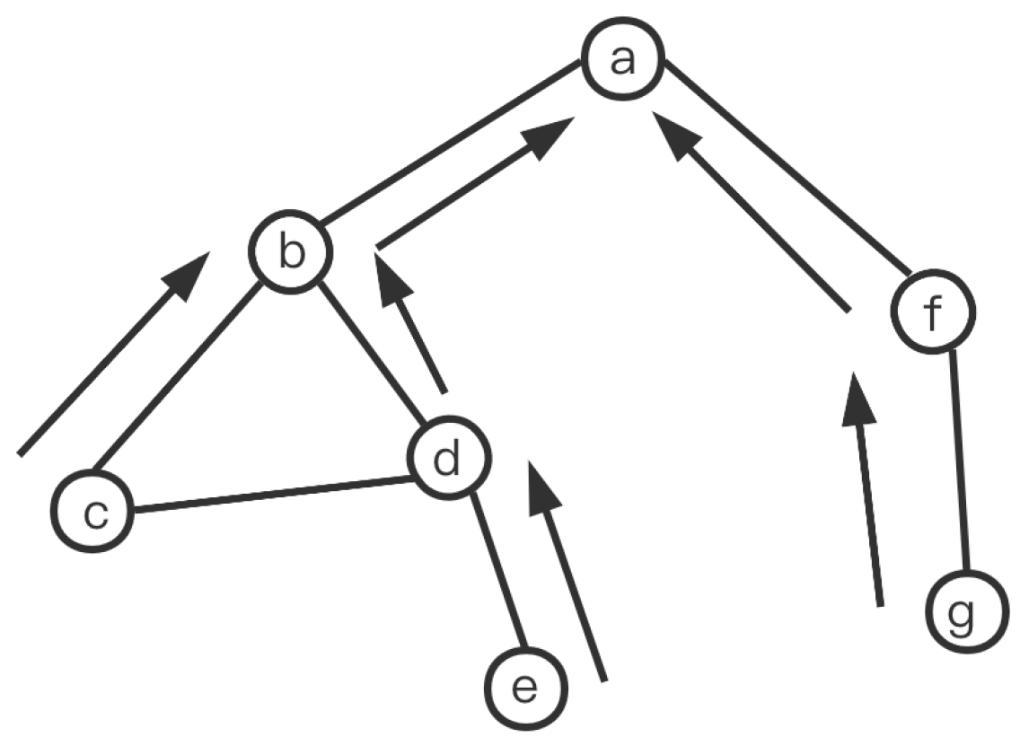
In
Figure 2, node
a constructs the RSPT with itself as the root node. It first floods requests to all other nodes in the network. Each node that receives the request will send the probe messages back to node
a. By following Algorithm 1, the RSPT can be constructed with nodes
c,
e, and
g as the leaves.
3.2. MJN Selection Method Implementation
In this section, we will discuss the process of selecting the most suitable MJN based on the information collected from the RSPT. By using the information gathered from RSPT, DR can calculate the downlink path cost related to each MJN, even when routing is asymmetric. The equation for calculating the path cost is shown in Equation (
1). DR will then choose the MJN with the lowest path cost to join the multicast tree.
In Equation (
1), we define several parameters to calculate the cost of a multicast path. The distance between nodes
i and
j is represented by
, while the topological diameter of the network is denoted by
. The reason for designing this parameter is that longer paths put more pressure on the network, so they should have a higher cost.
, , , and are four parameters that represent the load on the path. represents the number of MFT entries on the node with the highest load on the path. represents the bandwidth usage of the link with the highest load on the path. means the average number of MFT entries recorded by all nodes on the path. represents the average bandwidth utilization of all links on the path. The reason for considering these load parameters is to reduce load congestion and prevent paths from passing through nodes and links with high loads.
To normalize various types of loads, we introduce a maximum forwarding state quantity that a node can handle and a maximum load that a link can handle.
Next, we will introduce the determination method for each weight. In Formula (1), the values of and are both 0.3, the value of is 0.2, and the values of and are both 0.1. As PT and PL are the parameters that most intuitively measure the load status of the highest-loaded points and edges on the path, setting and to be larger can help avoid congestion of individual nodes and links, delaying the time to reach the network performance bottleneck. is also important. Setting it to be larger can help shorten the length of the multicast path and reduce the consumption of network resources. and measure the average load status of the path, which also helps to delay the time for the network to reach the performance bottleneck. However, through experiments, it has been found that their importance is not as significant as other parameters, so the values of and are relatively small.
In Formula (2), as the topology size increases, also increases accordingly. This is because in large topologies, in order to avoid excessive load concentration on nodes outside the detection range, each DR prioritizes selecting nodes within its own detection range. Since DR cannot obtain the path load status of nodes outside the detection range, it can easily lead to load congestion problems.
Upon computing the path cost for each MJN, DR selects the node with the minimum cost to join the multicast tree.
It can be seen that DR can make real-time decisions upon receiving join requests by utilizing cached information, thus ensuring low multicast service latency. Additionally, the method proposed does not require the participation of a central management node, making it a purely distributed approach that avoids central bottleneck issues and enhances multicast scalability.
4. Simulation
We used the Waxman model to generate four topological structures, each containing 200 nodes (Waxman200), 2k nodes (Waxman2000), 200k nodes (Waxman200k), and 2 million nodes (Waxman2000k). When choosing a baseline, our primary consideration is to select a method that has an impact; secondly, the baseline should be distributed and have the potential to be deployed in large-scale networks. Based on the above considerations, we have chosen the following three methods as baselines.
WAVE [
13]: Each time DR receives a join request, it needs to probe all nodes in the multicast tree and select the MJN with the lowest path load to join. The WAVE algorithm is suitable for asymmetric routing and has an impact on many algorithms [
14,
15,
16,
17];
Near: DR selects the nearest MJN to join. Many ICN multicast protocols use this method to select MJN [
26,
27,
28,
29]. This method cannot detect the path load status in the case of asymmetric routing;
SPT: DR adds the root node. Many IP multicast protocols use this method to select MJN [
13,
18,
19,
20]. This method cannot detect the path load status in the case of asymmetric routing.
Our experiment assumes that each multicast group occupies a bandwidth of 6 Mbps (2K video bandwidth), the bandwidth of each link is 10 Gbps (1500 multicast streams), and the switch can accommodate 1K forwarding status at most. Our experiments are conducted on a Dell R740xd PowerEdge server with two Xeon(R) Gold 5218R CPUs and 300 GB RAM.
In our experiments, the positions of DRs are distributed in nodes with relatively high degrees. This is because DR, as a link device between the internal and external networks, is a core device in a small area and therefore needs to be deployed in nodes with relatively high centrality. The number of DRs accounts for 1% to 0.1% of the total network nodes, which is a common simulation setting for sparse mode multicast [
17,
35]. Since sparse mode is the main mode for multimedia applications [
36,
37,
38], this paper simulates under sparse mode.
The value of in Formula (2) varies with changes in topology. For the waxman200 and waxman2000 topologies, since each DR can almost completely explore the topology, the value of has little effect on the results, so we set . In the waxman200k topology, we set to 1.5, and in the waxman2000k topology, we set to 2.
The traffic generation model in the experiment is as follows: for each multicast group, the source DR is randomly selected, and each multicast group has only one source DR. The number of receivers (group size) ranges from 1/20 to 1/3 of the total number of DRs, and their locations are randomly selected from all DRs [
17,
35]. The specific settings are shown in the
Table 2.
Additionally, in this experiment, the network routing is asymmetric, meaning that the route from point A to point B is often different from the route from point B to point A.
4.1. The Comparison of the Control Message Numbers
In this section, We compared the average number of control messages required for each algorithm to establish a multicast tree. As the number of control messages increases, the network burden becomes heavier, making this indicator very important. In the RSPT algorithm, the DR sends a request to the leaf nodes every certain period, which is set to send a request every time the DR processes 30 new multicast group members. In the WAVE algorithm, DR needs to detect all nodes in the multicast tree whenever a new group member joins. Therefore, we can anticipate that the control message count in RSPT will be much lower than that of WAVE. In contrast, the Near and SPT methods do not require any control message, so their control message count is zero.
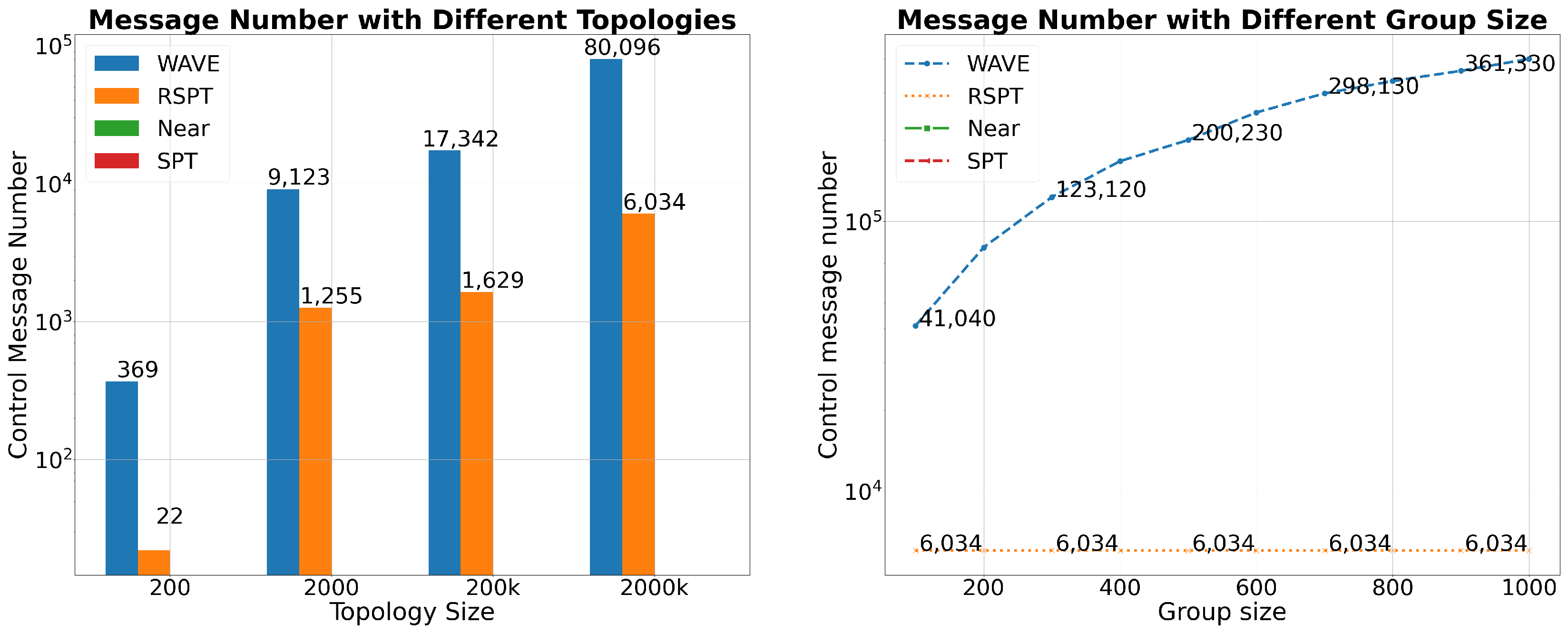
In the left graph of
Figure 3, we compared the control message counts of different algorithms in topologies of different sizes. Firstly, as the topology expands, the control message count gradually increases. The reason is that for the WAVE algorithm, as the topology grows, the size of the multicast tree also increases, and DR needs to probe more nodes; thus, the control message count gradually increases. For the RSPT algorithm, the larger the topology, the more nodes covered by DR neighbours, so the control message count also increases accordingly. In the topologies of 200, 2k, and 200k nodes, their diameters are 6, 8, and 13, respectively, and the DR’s probing diameter is 6. According to statistics, in these three topologies, the average number of nodes probed by DR is 134, 623, and 932, respectively. In the topology of 2 million nodes, the DR’s probing diameter expands to 4, so the number of probed nodes will increase significantly, with an average of 6789 nodes probed. In summary, for RSPT, the larger the topology, the more nodes DR needs to probe, and the more control messages are required. Secondly, we can see that the control message count of RSPT is about one-tenth to one-hundredth of that of WAVE, and the cost brought by RSPT to the network is much lower than that of WAVE.
In the right graph of
Figure 3, we compared the number of control messages for various algorithms in a topology with 2 million nodes. When each multicast group has 200 members, the number of control messages for RSPT is only 6034, while for WAVE it is 80,096, which is 7.5% of WAVE. As the number of group members increases, the number of control messages for WAVE gradually increases, while for RSPT it remains constant, eventually accounting for only about 1% of WAVE. The reason why RSPT can maintain the same number of control messages is that RSPT only detects the neighbourhood of DR, and its detection behaviour is not related to the size of the multicast tree. However, WAVE must detect the entire multicast tree. Therefore, as the number of group members increases and the multicast tree becomes larger, the number of control messages for WAVE will gradually increase.
The control messages of RSPT will not impose a heavy burden on the network. The control message payload of RSPT is relatively small, only about 20 bytes, and the sending period is relatively long. In this experiment, DR triggers a detection only after processing 30 multicast group requests, which takes about 10 s. Therefore, the bandwidth occupied by RSPT’s control message is below 1 Kb/s. In contrast, WAVE’s bandwidth usage can reach over 100 times that of RSPT, reaching the 1 Mb/s level. When the bandwidth usage of each multicast stream is in the Mb/s range, WAVE’s control message bandwidth usage will impose a significant burden on the bandwidth and network devices, while RSPT will not.
In short, RSPT is a cost-effective method.
4.2. Delay Comparison
The delay refers to the time from when DR receives the join request to when it calculates the MJN. We assume a propagation delay of 1ms for each link. The delay of WAVE consists of four parts. The first part is the forwarding delay of the request from the DR to the root node of the multicast tree. The second part is the delay of the request spreading from the root node to the leaf node. The third part is the forwarding delay of the control message from the node on the multicast tree to the DR, and the fourth part is the delay in obtaining MJNs from the NMRS. RSPT, Near, and SPT only have a delay in obtaining MJNs from the NMRS. In our experiment, we place the NMRS on the central node.
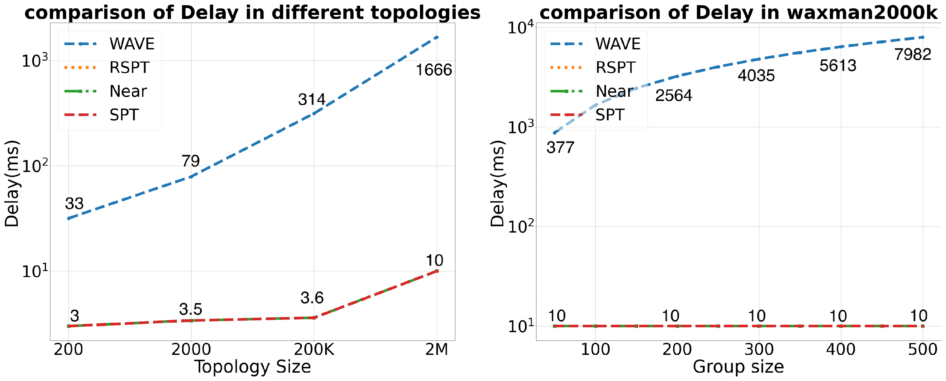
In the left part of
Figure 4, we conducted experiments in topologies of various sizes to compare the delay of different algorithms. It can be seen that the delay of WAVE increases with the topology size. This is because the larger the topology, the larger the multicast tree, and the longer it takes for the DR to complete the detection of all nodes on the multicast tree. In a topology of 200 nodes, the DR needs to spend at least 20 ms to process one join request on average. In a topology of 2 million points, the DR needs to spend 1600 ms. Compared to WAVE, RSPT, SPT, and Near have almost no delay, only a delay in obtaining the MJN list from the NMRS, which is less than 10 ms.
In the right part of
Figure 4, we conducted experiments in the topology with 2 million points. It can be seen that the delay of WAVE increases with the size of the multicast group. This is because the larger the multicast group, the larger the multicast tree, and the longer it takes for the DR to complete the detection of the multicast tree. However, the delay of RSPT, SPT, and Near are not affected by the group size at all. This indicates that RSPT, SPT, and Near can be applied to scenarios with extremely large group members, while WAVE cannot.
In short, RSPT is a low-latency method.
4.3. Traffic Congestion Comparison
In this experiment, we compared the traffic congestion of various methods. The degree of traffic congestion is an important indicator for evaluating MJN selection methods. Reasonable MJN selection methods can effectively reduce traffic congestion and improve multicast scalability. We use max link stress to measure traffic congestion. Max link stress refers to the number of multicast flows carried on the busiest link in the entire topology, measured in units of “group”.
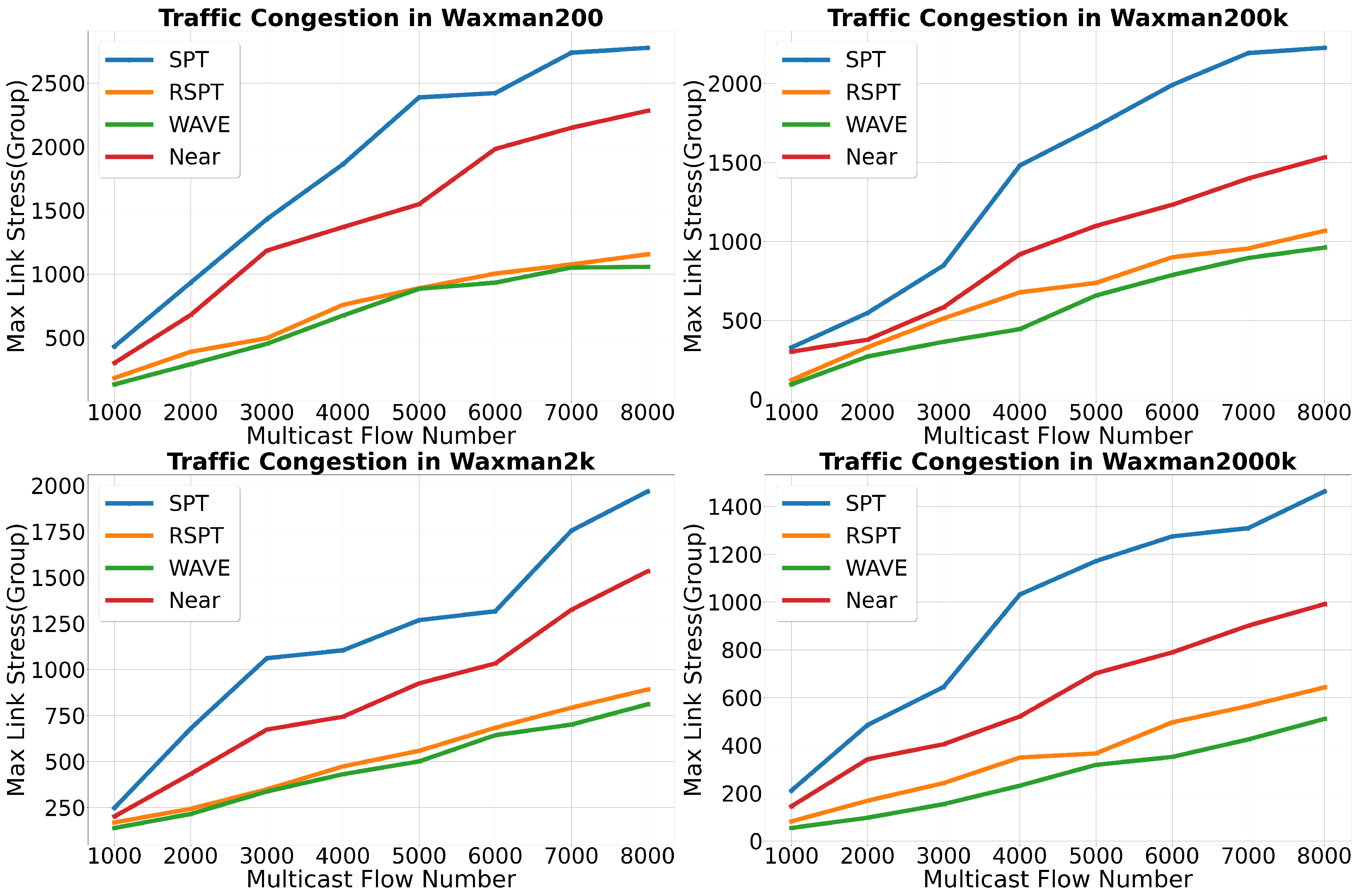
Results are shown in
Figure 5, It can be seen that RSPT, like WAVE, can effectively balance the traffic in the network. In the 200 and 2000-node topologies, RSPT and WAVE perform almost identically at certain times, with an average performance difference of less than 5%. This is because the diameter of these two topologies is 5 and 8, respectively, and each DR can explore a topology with a diameter of 6, allowing for the very precise exploration of most of the network. However, the detection of RSPT is not in real-time. In fact, during the experiment process, DR will only initiate a detection and update the cached network state after processing 30 join requests. This delay causes RSPT to not be able to perceive the network state in real-time like WAVE, which results in performance differences between RSPT and WAVE, even in small topologies. In the 200,000-node topology with a diameter of 16, and the 2 million-node topology with a diameter of 34, RSPT can only explore part of the topology with 6 or 8 hops, resulting in performance degradation. The impact of topology size on performance will be further analyzed later.
Moreover, in each topology, the performance of RSPT is far superior to SPT and Near. This is because RSPT can effectively detect the load on the multicast path, while Near and SPT cannot. SPT establishes a long forwarding path from the root node to the receiver, which cannot sense the network load status, and puts a heavy burden on the network due to the long multicast path. Although Near selects the nearest MJN, it also causes traffic congestion because it cannot sense the network load status.
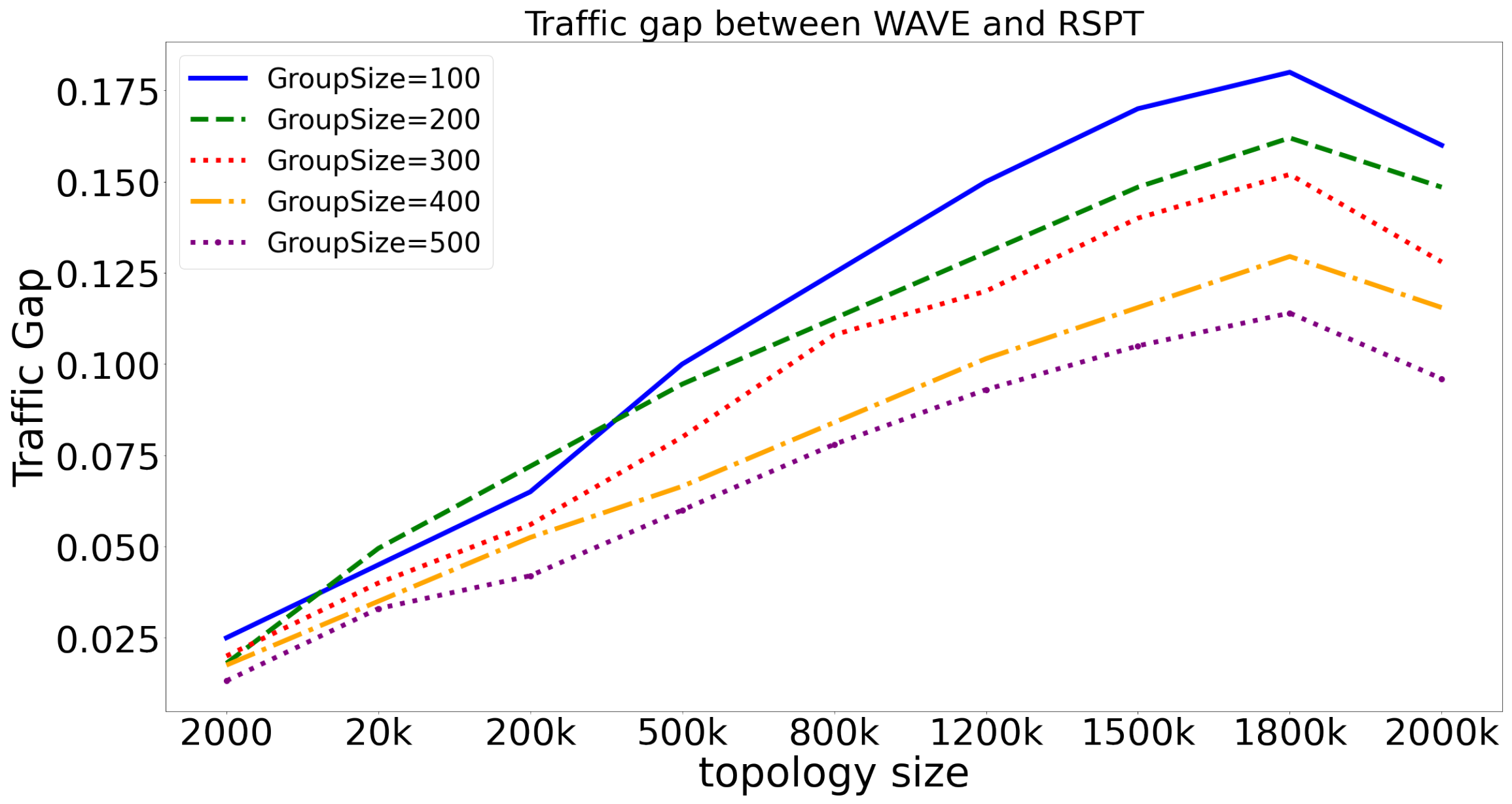
To demonstrate the impact of topology size on the performance of RSPT and WAVE, we compare the relative performance gap between the two on topologies of different sizes. Results are shown in
Figure 6. To illustrate the gap between RSPT and WAVE, we defined the traffic gap index, that can be expressed by Formula (
3).
represents the max link stress of the network. TrafficGap refers to the difference in traffic congestion level between RSPT and WAVE. As the traffic congestion level of RSPT has always been higher than that of WAVE, this index is greater than 0. The larger the value of this index, the more serious the traffic congestion of RSPT compared to WAVE, and the worse the performance relative to WAVE. The smaller the value, the more similar the traffic congestion level between RSPT and WAVE, and the closer their performance.
Through
Figure 6, we can observe that as the topology scale increases, the TrafficGap index also gradually increases. However, when the topology size reaches 2 million points, the TrafficGap index sharply drops. This is because as the topology grows, the proportion of the neighbourhood that RSPT can detect in the entire topology decreases, leading to the imprecise evaluation of path cost by DR. This increases the traffic load congestion of RSPT and also increases the traffic gap index. However, when the size of the topology reaches 2 million nodes, the detection radius of RSPT changes from 3 to 4 hops, and DR can perceive a larger range of the network, thereby reducing the traffic load congestion and causing a sudden drop in the traffic gap index.
From
Figure 6, we can also see that as the number of multicast group members increases, the TrafficGap gradually decreases. This is because as the number of multicast group members increases, the multicast tree becomes larger, allowing DR to perceive the load status of more multicast tree nodes. This reduces the degree of flow congestion of RSPT, that is, the TrafficGap decreases.
Overall, the maximum TrafficGap is around 17%, and in topologies with less than 200,000 nodes, the TrafficGap is below 5%. Therefore, the degree of flow congestion of RSPT and WAVE is quite similar, especially when the topology node number is less than 200,000.
4.4. MFT Congestion Comparison
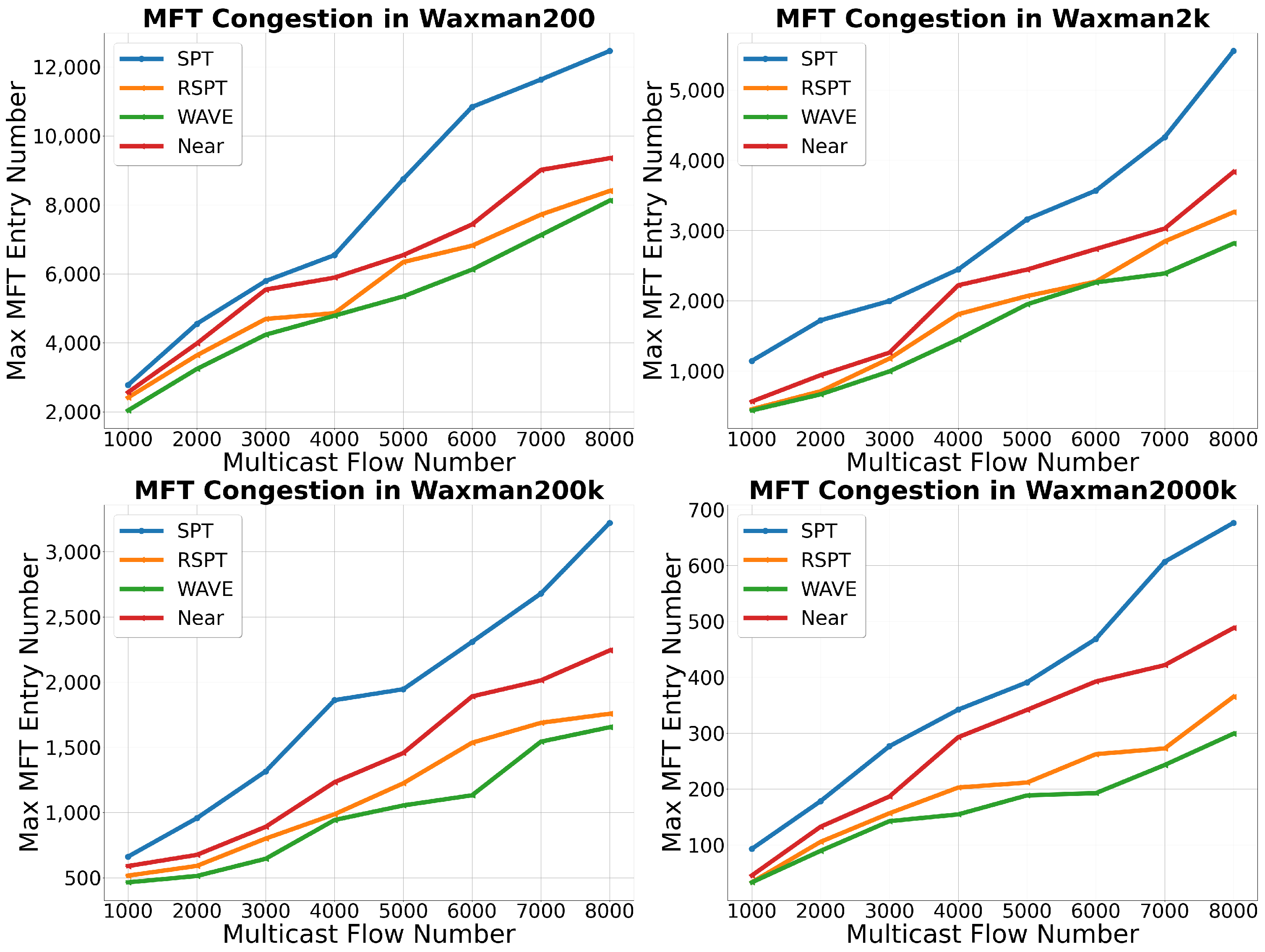
The level of MFT congestion is another important indicator for measuring the effectiveness of MJN selection methods. A reasonable MJN selection method can effectively reduce MFT congestion, avoid single-point performance bottlenecks, and improve multicast scalability.
In
Figure 7, we have illustrated the level of MFT congestion for various algorithms. We use max MFT entry number to measure MFT congestion. The max MFT entry number refers to the number of multicast forwarding states carried by the most heavily loaded node in the entire topology, measured in units of “count”.
Compared to the traffic load, it is more challenging to balance multicast forwarding states. This is because the forwarding state is maintained on the node, and a node can have multiple links. Once a node is in a multicast tree, its forwarding state increases by one. However, only one to two links in all of the node’s links will have an increase in load. Therefore, the granularity of adjustment for link states are smaller than that of the forwarding states. This results in WAVE or RSPT having a more severe congestion level for forwarding states than for traffic load. Specifically, the congestion level for forwarding states in WAVE and RSPT can reach about 40% of that achieved by SPT, while the congestion level for the traffic load is only about 30% of that achieved by SPT.
The curve of MFT congestion for different algorithms is similar to that of link stress congestion. The performance difference between RSPT and WAVE is within 12%, indicating that RSPT can effectively balance a forwarding state load. Although Near can join the multicast tree using the shortest path, its performance is slightly inferior to RSPT and WAVE due to its inability to avoid high-load nodes. Due to building long paths, SPT can increase the workload of more nodes; At the same time, SPT cannot perceive the network load status. Therefore, SPT has the worst performance.
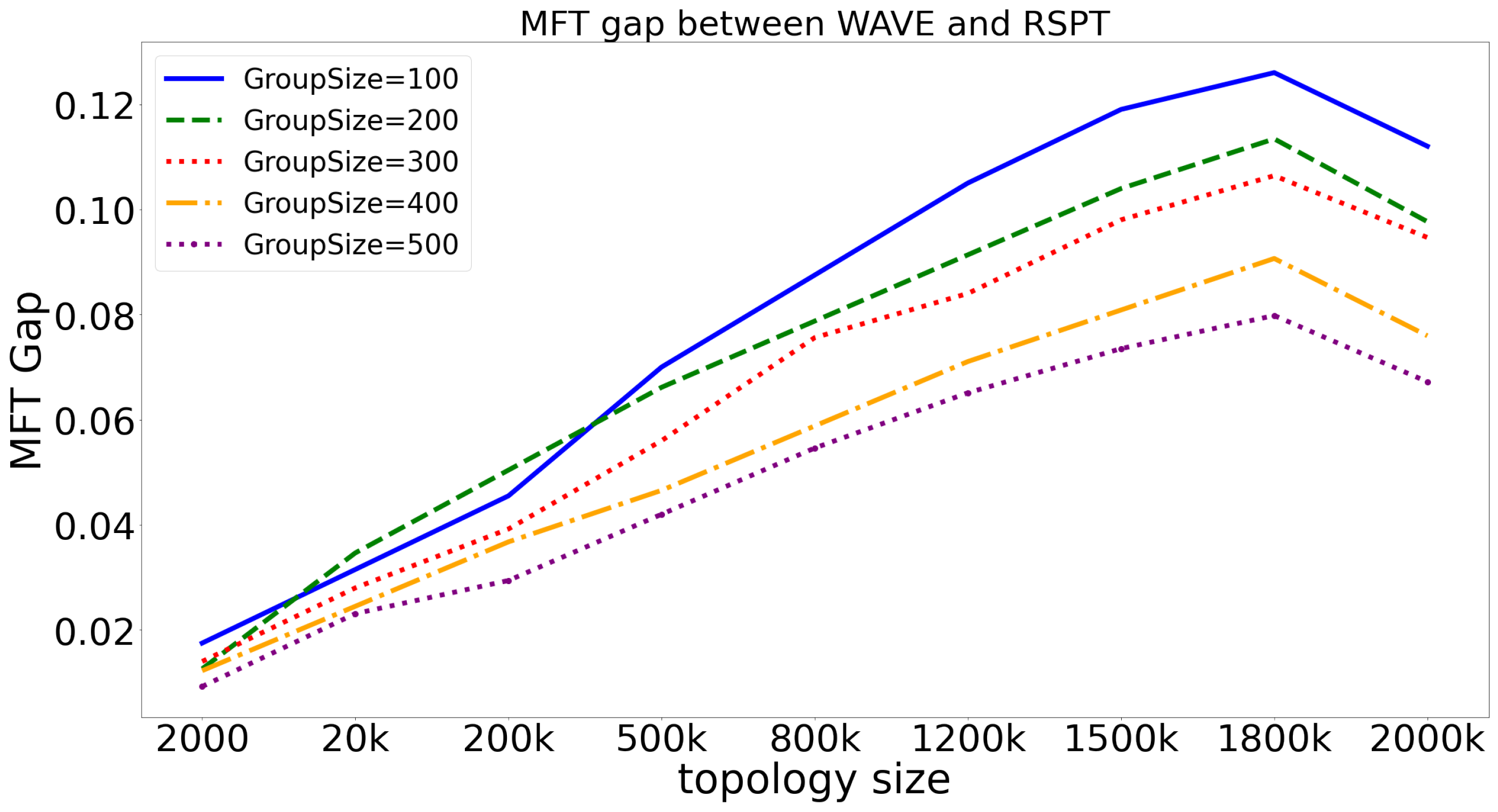
To demonstrate the impact of topology size on the performance of RSPT and WAVE, we compare the relative performance gap between the two on topologies of different sizes. Results are shown in
Figure 8. To illustrate the average difference between RSPT and WAVE, we defined the MFT gap index, which can be expressed by Formula (
4).
represents the max MFT entry number of the network. MFTGap refers to the difference in forwarding state congestion level between RSPT and WAVE. As the forwarding state congestion level of RSPT has always been higher than that of WAVE, this index is greater than 0. The larger the value of this index, the more serious the forwarding state congestion of RSPT compared to WAVE, and the worse the performance relative to WAVE. The smaller the value, the more similar the forwarding state congestion level between RSPT and WAVE, and the closer their performance.
The conclusion we obtained from
Figure 8 is similar to that from
Figure 6. The difference lies in that, from an overall perspective, the MFTGap index is around 12%, which is 5% lower than the TrafficGap index. This is because achieving balance in the forwarding state is difficult for both WAVE and RSPT, which we have discussed before. Therefore, the difference between the two is not as significant as when balancing the traffic load.
4.5. Multicast Capacity Comparison
Multicast capacity refers to the number of multicast groups that a network can accommodate. The reason why there is a limit to the number of multicast groups that a network can accommodate is mainly due to the limit of the forwarding state that nodes can accommodate and the limit of the link bandwidth. The experiment will terminate when the network can no longer accommodate more multicast groups. At this point, the number of multicast groups that the network can accommodate is the multicast capacity.
In this experiment, we assume that each node can accommodate up to 1k forwarding states, and each link can accommodate up to 1.5 k multicast flows. This experimental setup is based on commercial switching device, such as the Huawei CloudEngine S16700 series and CloudEngine S8700 series switches [
39].
As can be seen from
Table 3, SPT has the minimum multicast capacity because it establishes long multicast paths and cannot perceive the network load status, making it easy to cause load congestion. WAVE has the largest multicast capacity because it can detect the network load most accurately. The multicast capacity of RSPT is similar to that of WAVE, reaching 94%, 87%, 82%, and 89% of WAVE performance in four different topologies, respectively. At the same time, the multicast capacity of RSPT is 2.34 times that of SPT and 1.94 times that of Near. The reason why RSPT can have such a similar performance as WAVE and significantly surpass SPT and Near is because it obtains the load status that can effectively detect the multicast path established downlink, thereby avoiding high-load links and nodes.
It is worth noting that the performance gap between RSPT and WAVE first increases and then decreases. This is because as the topology increases, RSPT’s perception error will become larger, and therefore the performance gap with WAVE will increase. However, in the topology of 2 million points, RSPT’s detection range has been increased to 4, so the perception accuracy has been improved, and the gap with WAVE has been reduced. This is in line with our previous analysis.
It can be seen from
Table 3 that the larger the network, the greater its multicast capacity. This is easily understandable. With a larger network, there is more room for adjustment in the multicast tree, which is more conducive to avoiding high-load areas. Therefore, larger networks are less likely to experience congestion compared to smaller networks, and can accommodate more multicast groups.
4.6. Simulation Conclusion
By comparing the number of control messages and delays, it can be proved that the method proposed in this article has the advantages of low cost (using fewer control messages) and low latency (almost real-time response). In addition, by comparing the traffic congestion level, the forwarding status congestion level, and multicast capacity, we can find that the proposed method can reduce load congestion and improve multicast capacity.
Among existing methods, Near and SPT are two MJN selection methods that have low processing delays and minimal control messages. RSPT has more than twice the multicast capacity improvement compared to Near and SPT, so it can be chosen as the MJN selection method when a large multicast capacity is required. WAVE has the largest multicast capacity, but it has a large amount of control messages and extremely high processing delays. If deployed in practical engineering environments, it will greatly reduce the quality of user services and bring a heavy burden to the network. Based on this, in practical engineering environments, RSPT should be chosen as the MJN selection method instead of WAVE.


