Article

A Strategy-Based Formal Approach for Fog Systems Analysis

1
LIRE Laboratory, TLSI Department, Constantine 2 University, Constantine 25000, Algeria
2
LIUPPA Laboratory, Universite de Pau et des Pays de l’Adour, E2S UPPA, LIUPPA, 64000 Pau, France
*
Author to whom correspondence should be addressed.
Future Internet 2022, 14(2), 52; https://doi.org/10.3390/fi14020052
Submission received: 13 January 2022 / Revised: 1 February 2022 / Accepted: 4 February 2022 / Published: 9 February 2022
(This article belongs to the Section Network Virtualization and Edge/Fog Computing)

Abstract

:
Fog systems are a new emergent technology having a wide range of architectures and pronounced needs making their design complex. Consequently, the design of fog systems is crucial, including service portability and interoperability between the various elements of a system being the most essential aspects of fog computing. This article presents a fog system cross-layer architecture as a first step of such a design to provide a graphical and conceptual description. Then, a BiAgents* (Bigraphical Agents) formal model is defined to provide a rigorous description of physical, virtual, and behavioural aspects of Fog systems. Besides, this formalisation is implemented and executed under a Maude strategy system. The proposed approach is illustrated through a case study: an airport terminal Luggage Inspection System (LIS) while checking the correctness of its relevant properties: the portability of data and their interoperability. The integration of the Maude strategies in the rewriting of Fog system states made it possible to guide the execution of the model and its analysis.

1. Introduction

Fog computing is a paradigm bridging the gap between cloud and IoT devices, enabling computing at the edge of the network. Thus, computation networking, decision making, storage, and data management is made in the path between the IoT and the cloud. The OpenFog Consortium [1] defines fog computing as a horizontal platform allowing computing operations to be dispersed across platforms and sectors and as a vertical platform that encourages isolated applications. In fact, an IoT architecture may be defined as a superposition of layers, permitting data to be treated from the hardware to the applications located in the cloud. However, the cloud still suffers from some limitations such as connectivity, distribution, heterogeneity, and latency. Fog computing is introduced to tackle these challenges; actually, it supports a variety of IoT applications including transportation, agriculture, smart cities, smart buildings, healthcare, hospitality, and financial services, just to name a few. Further, it provides effective methods to overcome many limitations of existing computing architectures related to cloud and IoT systems. This emerging field in computer science has induced intensive investigations and studies during the last decade. Many researchers are working on its standardisation as the OpenFog Consortium has established the IEEE Std 1934-2018 standard for a definition of a fog architecture and its pillars. They met on its following main features [2,3]:
  • Low latency and location awareness: Fog computing provides location awareness by allowing fog nodes to be deployed in various places. Additionally, due to the fog proximity to end devices, it has a reduced latency while processing data.
  • Geographical distribution: Unlike the centralised cloud, the fog provides dispersed services and applications that may be installed anywhere.
  • Scalability: Fog provides distributed computing and storage resources that can handle such massive end devices.
  • Mobility: One of the most significant features of fog systems is their capacity to connect directly to mobile devices, allowing mobility technologies.
  • Interactions: Instead of the batch processing used in the cloud, fog systems enable real-time interactions between fog nodes.
  • Heterogeneity: Different manufacturers create fog nodes or end devices, which come in a variety of types and must be installed according to their platforms.
  • Interoperability: Fog components may interoperate with one other and perform across different domains and service providers.
The management and coordination of such heterogeneous and geographically widespread IoT devices, as well as the selection of appropriate resources, is incredibly challenging. Moreover, IoT devices have the capacity to evolve and dynamically modify their workflow composition. The internal properties and performance of IoT devices are, thus, affected. As a result, fog nodes require intelligent and automated elements to manage this dynamicity.
Such complex systems necessitate a conceptual design using the appropriate software engineering techniques. This will provide a high level of abstraction for them to address all of the aforementioned issues. In the context of fog systems engineering, formal methods are the best choice; they give the necessary rigour to describe and enforce high-level fog system specifications. In this context, the fundamental raised challenges are:
  • How to abstract this complex type of systems to deal with their heterogeneous, dynamical, geographically widespread, and intelligent aspects;
  • What formalism is appropriate to design structural and behavioural aspects of fog systems;
  • How to execute and analyse these formal models.
It is worth mentioning that the authors in [4] distinguish two types of approaches to model and understand dynamic and unpredictable behaviour of fog systems: software architecture-based approaches and algorithm-based ones. This classification is adopted since the majority of studies in the field look at the challenges from these both sides. In fact, some works such as [5,6,7] focus on the physical aspects of fog systems using architectures, graphical modelling, and a formal one. Others focused on the behavioural study of fog systems, such as [8], with algorithms.
The novelty of this work consists in the abstract definition of the intelligent and distributed behaviour of fog systems. We propose an incremental approach with diverse specification and analysis phases (Figure 1). By adding a communication layer containing internal and external protocols, in addition to managing agents in the fog layer of a fog system’s architecture, the management of the fog system’s elements is improved, and the communication between the different layers is well organised. Thus, time latency decreases the distribution of the different applications according to their role (critical or not) is possible. In addition, by redefining the formalism of BiAgents by improving agents’ behaviour, we allow the system to take as many pathways as it needs to, on the basis of an analysis, rather than just a binary decision as in [9].
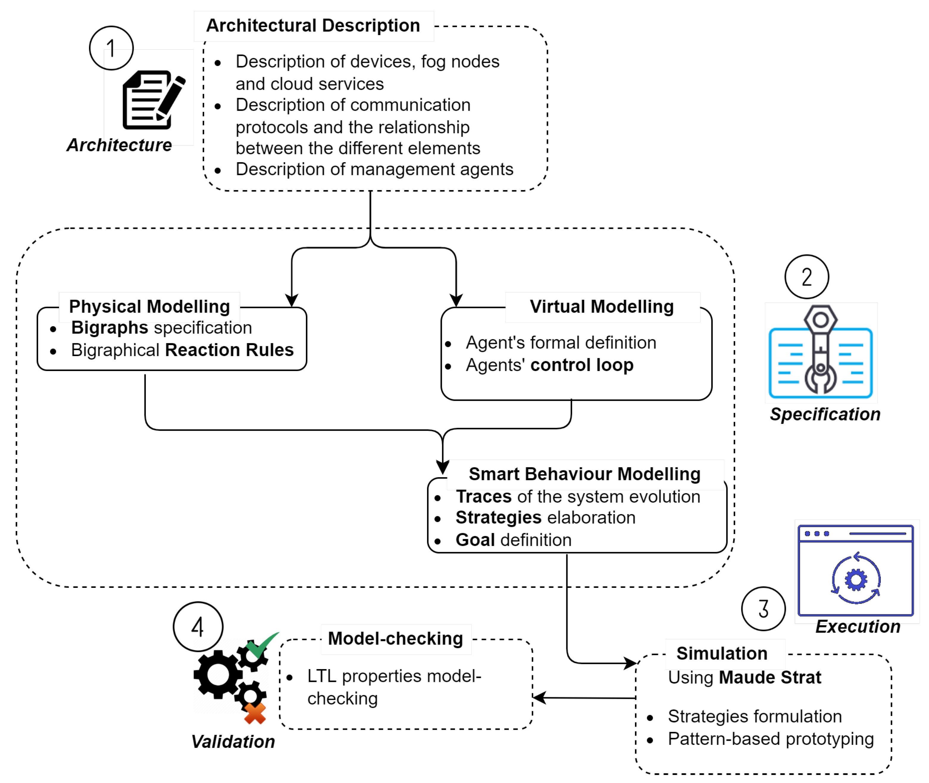
  • First, we propose an architecture for fog systems. This architecture relies on many overlapping factors that should be considered earlier in the design phase. It focuses on the orchestration of fog elements, cloud elements, and IoT ones, in addition to communication issues between these elements by managing intra- and inter-layer communication using dedicated agents.
  • Then, in the second step (Figure 1), we propose a model based on the formalism of BiAgents* (Bigraphical agents), a combination of bigraphs [10] and mobile agents [11], to model both physical and virtual aspects of complex systems. It permits also to represent its smart behaviour using the formal traces concept. The bigraphical part allows representing geographical dispersion of a fog system’s elements in addition to their heterogeneity. Besides, the dynamic behaviour of a fog system is defined by a combination of the bigraph reaction rules and agents’ states evolution.
  • In the third step (Figure 1), we make a guided execution of this specification model using the Maude strategy tool [12] while implementing the different BiAgents* aspects in Maude. This execution permits a simulation of different plausible scenarios of a fog system. By using the extension of Maude with strategies, we have the ability to implement all the dimensions of a BiAgents* model.
  • In the last step of our approach, we analyse formally the specified behaviours using the Maude strategy model checker.
In this study, we were interested in checking the portability of data properties and their interoperability (syntactic and semantic).
The rest of the article is organised as follows. Section 2 introduces our fog architecture proposition Cross-Layer Architecture for Fog computing (CLA4Fog) with its different layers and views. Section 3 gives a case of study we describe to instantiate the proposed architecture. In Section 4, we present a BiAgents* specification of a fog system that deals with the physical structure, the virtual structure, and the smart behaviour. Section 5 describes the execution of the model using the Maude strategy. It also shows how qualitative properties are checked using Maude strategy’s model checker. Section 6 discusses related work. Finally, Section 7 concludes the article and discusses future directions.

2. Cross-Layer Architecture for Fog Systems
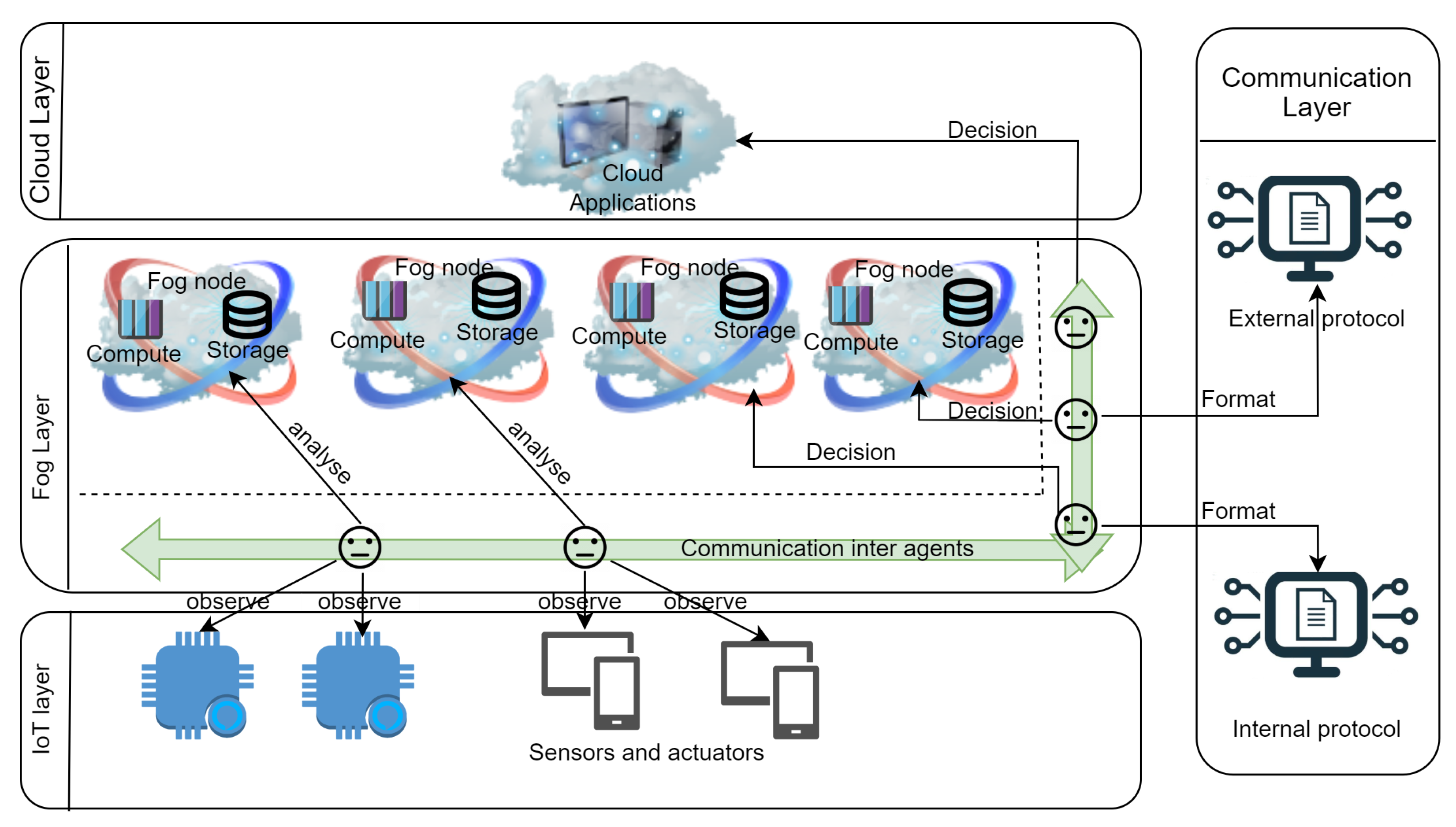
Recently, a rapid rise in interest in fog computing is widely observed. Some research works have proposed reference architectures for fog computing in order to facilitate its comprehension and development. In this section, we present some of these architectures and introduce our proposition.
The OpenFog Consortium group [1] has developed a reference architecture that addresses some issues in cloud computing such as security, latency, and efficiency. Actually, the fog nodes in this architecture are distributed over several layers. The consortium has published deployment hierarchies in which the combination of fog and the cloud is used to address various domain scenarios.
Additionally, the architecture proposed by Cisco [13] describes the role of IoT in the development of fog computing. The fog layer is responsible for assembling data collected by the sensors and the terminal devices, processing this data locally, and then responding with control commands (requests) to the actuators. On the other hand, the fog layer is capable of filtering, aggregating, and then redirecting this data, possibly, to a remote data centre.
Moreover, the fog nodes in the architecture proposed by the NIST [14] are context-sensitive and support a common data management and communication system. They can be organized in clusters, either vertically (to support insulation) or horizontally (to support federation), with respect to the latency distance of the fog nodes or with respect to intelligent terminal equipment. Fog computing minimises the response time of requests to supported applications and provides terminal devices with local computing resources and, if necessary, network connectivity to centralised services. Hence, the NIST proposed another type of fog node, the Mist.
In parallel, further research works elaborated other architectures for fog systems on the basis of these known ones [15,16,17].
In the same thought, we propose a cross-layer architecture, named CLA4Fog to improve the overall smartness of a fog system. In fact, this architecture extends an IoT architecture found in [18], to deal with the fog system’s elements, and we propose to locate all managing agents in a novel-single layer: the fog layer. Along with these agents, the fog nodes responsible for critical data processing are defined. The communication layer is enriched with additional functionalities.
The proposed CLA4Fog architecture, as shown in Figure 2, has four layers (IoT, communication, fog, and cloud) with three essential views (physical, virtual, and interactional). We detail for each layer possible views being addressed.
  • IoT layer:
    • Physical view: represents the different sensors that capture data from the environment and actuators that have a direct impact on it.
    • Interactional view: all the devices communicate data with the agents in the layer above.
  • Communication layer:
    • Physical view: represents external and internal protocols that permit to format and root data from IoT devices to both fog and cloud applications.
    • Interactional view: protocols embedded in this layer are used by associated agents to format data for either fog or the cloud.
  • Fog layer:
    • Physical view: depicts fog nodes responsible for critical computing, as a computing and storage.
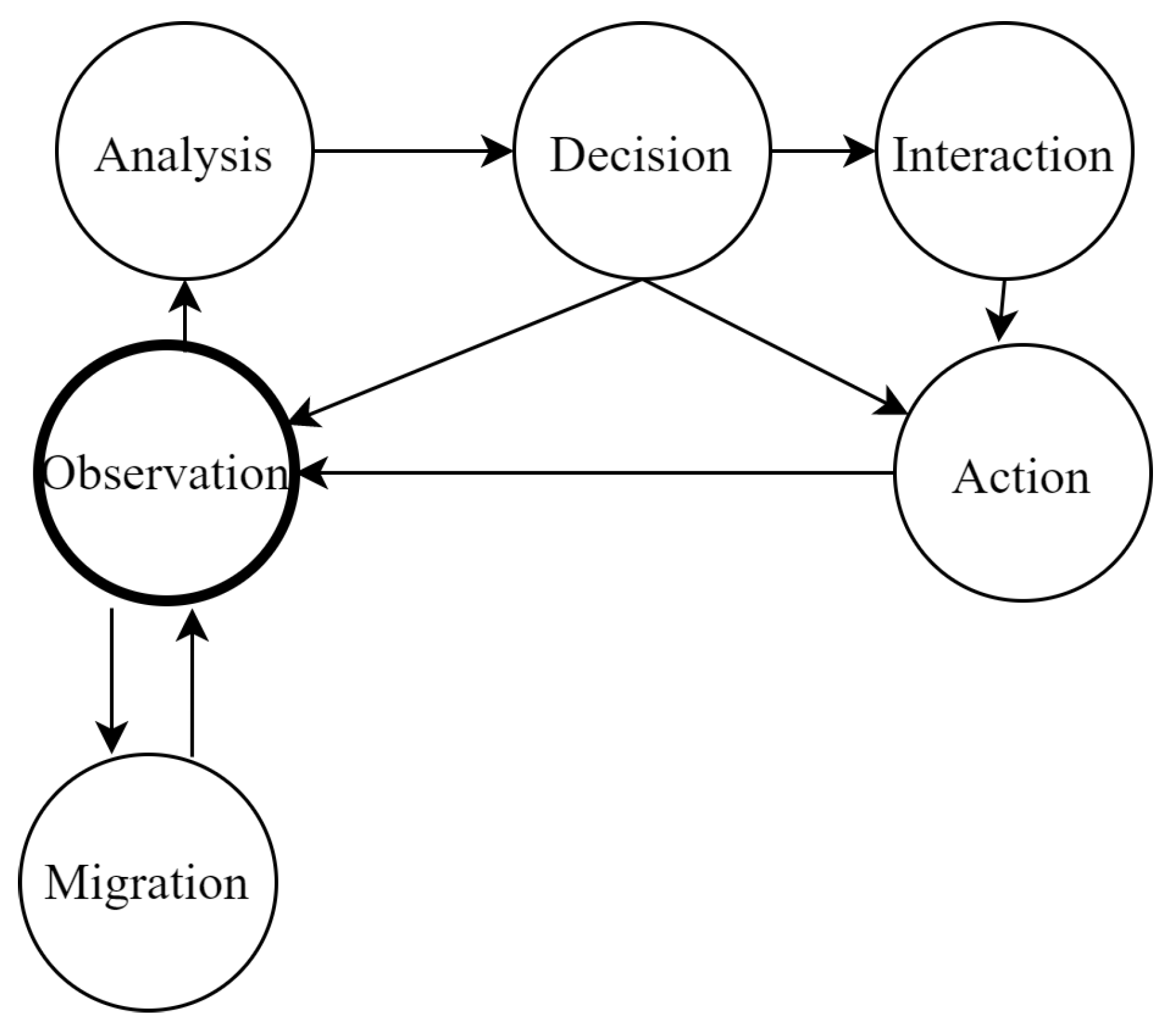
    • Virtual view: composed of intelligent agents that are responsible for managing the whole system. Each device type in the IoT layer is precisely managed by one agent, and each protocol type in the communication layer is also managed by one agent. The decisions of those agents orchestrate fog nodes and cloud applications. Each agent may observe, analyse, and interact. On the basis of at least one of these actions, the agent acts on the system elements.
    • Interactional view: the interaction between agents permits all the agents to communicate between each other. On the other, agents interact with the different system’s elements nodes to analyse data and to make a decision if necessary.
  • Cloud layer:
    • Physical view: concerns all cloud applications involved in the system.
    • Interactional view: reflects the interaction between the agent responsible for making a decision for data that must be treated in the cloud.
This architecture Figure 2 can be defined as a set of four layers:
C L A 4 F o g = { I o T , C o m m u n i c a t i o n , F o g , C l o u d }
With each layer containing entities according to the architecture’s view.
  • Physical view: I o T = { D e v i c e s } ; C o m m u n i c a t i o n = { P r o t o c o l s } ; F o g = { F o g _ N o d e s } ; c l o u d = { C l o u d _ S e r v i c e s } .
  • Virtual view: I o T = { } ; C o m m u n i c a t i o n = { } ; F o g = { a S , a F C , a C o m , a C C } ;
    C l o u d = { } .
  • Interactional view: I o T = { D e v i c e s P r o t o c o l s } ; C o m m u n i c a t i o n = { P r o t o c o l s C l o u d s y s t e m s / F o g n o d e s } ; F o g = { F o g _ N o d e s d e v i c e s , A g e n t s A g e n t s } , C l o u d = { C l o u d _ S e r v i c e s D e v i c e s } .
This definition does not represent well all the dimensions of CLA4Fog. In fact, the proposed architecture abstracts the complexity of fog systems and constitutes a prerequisite and inevitable step prior to the formal model. In the following section, we illustrate the proposed CLA4Fog through a concrete case study. As stated by Rhonda Dirvin and Matt Vasey (members of OpenFog Consortiom), there are some IoT systems that illustrate, better than others, the usefulness of fog computing.

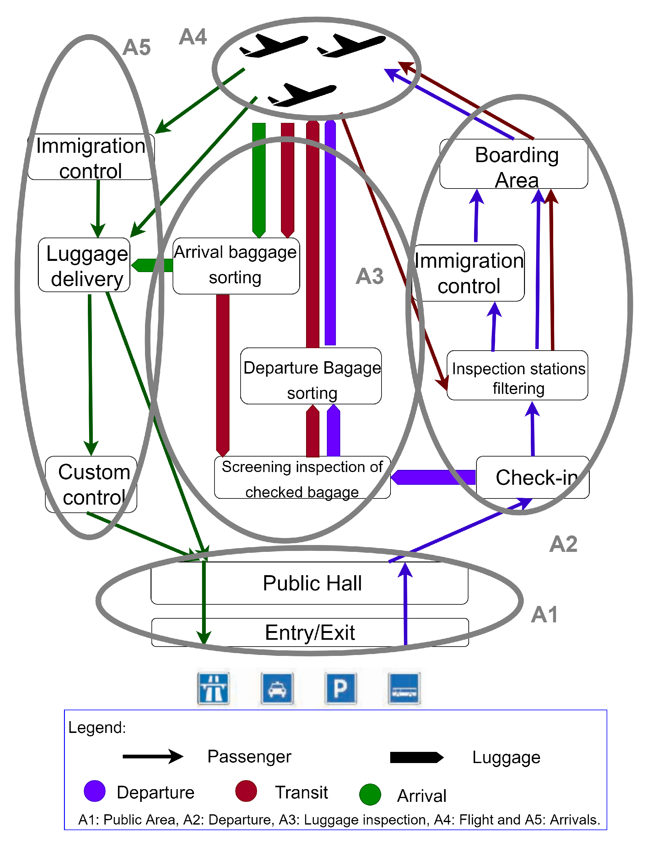
3. Motivating Case Study

In order to ensure public safety, video cameras are used in several places of daily life: car parks, large buildings, and various public and private spaces. With the help of a fog architecture, video processing is intelligently partitioned between nodes co-located with cameras and the cloud. This allows real-time tracking, anomaly detection, and the collection of information from data captured over long-time intervals. Our choice is towards modelling a video surveillance system for airport terminals. The surveillance of airport terminals permits to fight terrorism, makes a real-time surveillance for all the departments, advances video analytics, etc. Using a fog architecture, video transmission is intelligently partitioned between fog nodes, co-located with cameras, and the cloud. Figure 3 illustrates a generic configuration inspired by [19] of any airport and its possible functioning services
This system should monitor safety checkpoints for congestion, criminal behaviour, confrontations, and passengers posing possible risks. Cameras in luggage-claim areas should be in position to deter fraud and to watch for potentially unsafe objects. In general, any airport may be divided into five areas (A1, A2, …, A5) of surveillance as shown in Figure 3. In this article, we propose an abstract architecture based on the fog computing paradigm for the Luggage Inspection System (LIS), which is located in area A3. This surveillance system checks:
  • If the lines are busy (by counting the number of trays).
  • If bar codes are identifiable.
  • If the bags are acceptable; unacceptable bags are round-shaped with long straps and the ones tied with ropes.
We instantiate CLA4Fog by defining all the elements embedded in its four layers (see Table 1):
  • The IoT layer contains three sensors: Bag scanner, Bar-code scanner, and camera in addition to one actuator: Screen.
  • The communication layer includes internal protocols that format data using the JSON format, and external protocols format data using XML. Internal protocols are responsible of the communication between layers of a system, and external ones are responsible for the communication between different systems in the network.
  • The fog layer comprises two principal fog nodes: Recognition and alert fog nodes and all the agents that are hosted initially in the fog layer, scattered in the fog nodes. In this system, we define three sensor agents a S 1 , a S 2 , and a S 3 (a sensor agent instantiation for each sensor), one fog control agent a F C , two communication control agents a I C o m and a E C o m (internal and external communication), and finally one cloud control agent a C C . Each agent manages a physical element of the architecture making a general management of the system.
  • The cloud layer is defined by a cloud node responsible for analysing data and storing it.
There are different interactions between the elements of CLA4Fog (physical and virtual). The physical elements share data in order to compute, analyse, format, or store it. Agents communicate between each other in order to orchestrate the behaviour of the system.
The different sensors collect data from the physical world, and the various sensor agents a S 1 , a S 2 , and a S 3 use this data from their interfaces then observe this data and analyse it. a S 1 , a S 2 , or a S 3 decides whether there is an anomaly or not. If from the camera there is more or less than 10,000 trays counted, or the bar code detected from the bar-code scanner is an identifiable bar code, or a dangerous bag is detected (from the bags scanner), then there is an anomaly. The concerned sensor agent sends captured data to a I C o m . After analysis, a I C o m formats captured data using the defined internal communication protocols. Then, it communicates with the a F C and sends formatted data to the fog nodes. a F C treats the formatted data. With the help of the Alert Fog Service and the Recognition Fog Service a F C warns end-users by showing this warning on the screens.
If there is no anomaly, the concerned sensor agent a S 1 , a S 2 , or a S 3 shall send collected data to the a E C o m . The latter collects the data, formats it with the external communication protocol, and sends it to the analysis and storage cloud service. a E C o m later interacts with the a C C and informs it of the data sent to the analysis system. After that, a C C will display the storage confirmation on the screens.
The instantiation of CLA4Fog according to the case study LIS is presented in Table 1.
The instantiated architecture of CLA4Fog representing the inspection system LIS minimises its complexity in terms of geographically distributed services and the number of hardware and software components. It guaranties also a reduction in time latency and non-congestion of the bandwidth in comparison to cloud systems by providing fog nodes between cloud and IoT layers.
To ensure that this system can function properly and in a flexible way, we provide a formal specification of this architecture, on the basis of the BiAgents* formalism. Thus, we contribute by defining a fog system through its various aspects that are represented (or not) by this architecture (Figure 2).
Physical part
Virtual part
Interactional and control part
Functional properties part
We note that, using CLA4Fog architecture, we are not able to specify the smart behaviour of this system—how an agent may interact to fulfil some functional requirements such as, for instance, the portability of data and the interoperability of the LIS system in our case study. Indeed, the syntactical interoperability means that the message content must be coded before it can be sent as an XML or JSON file. The sender encodes the message, and the receiver decodes it [20]. Semantic interoperability lets different agents, programs, and applications to communicate correct information [20]. The portability of data means that we have to guarantee that moving data across various runtime systems and subsystems does not need to rewrite them entirely or partially [21].

4. BiAgents* Model Specification
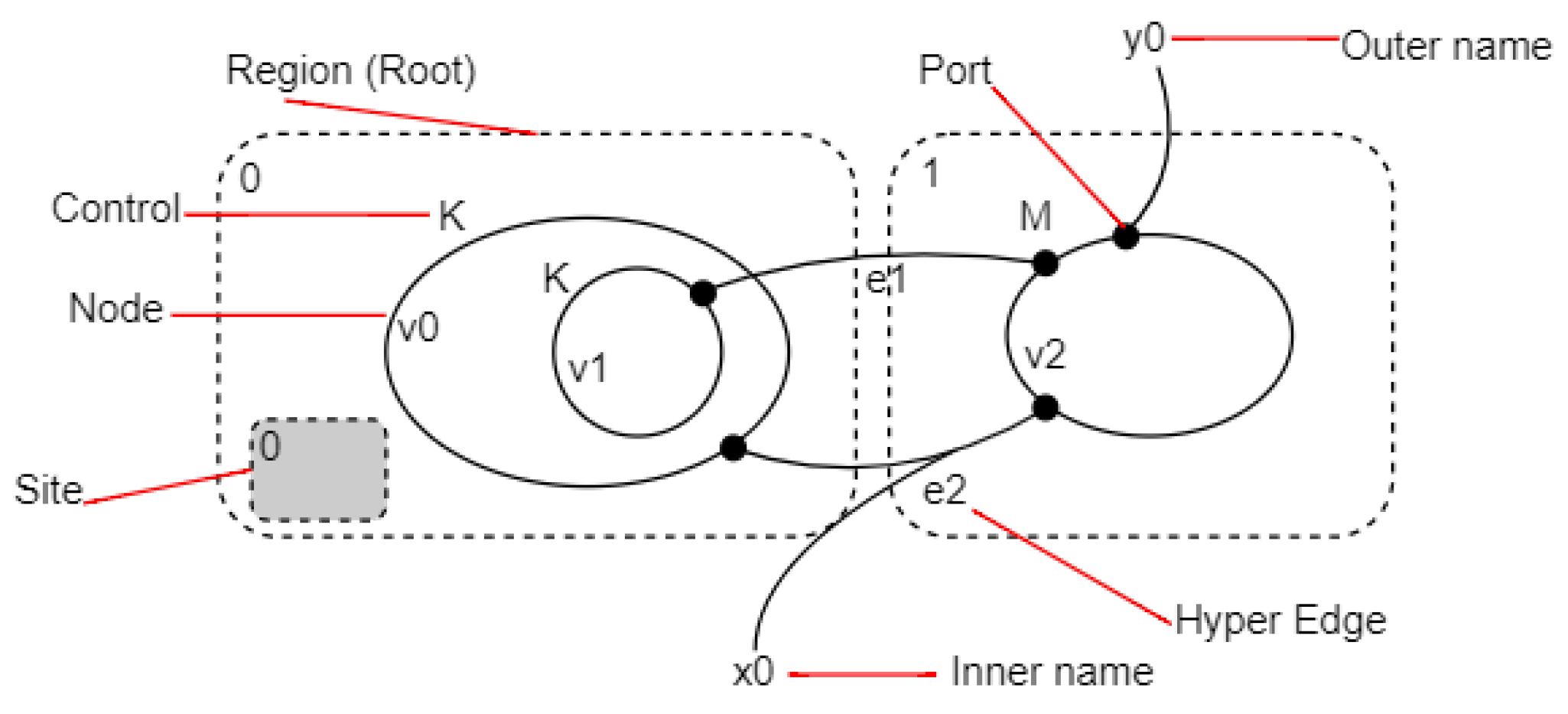
In this section, we show how we transform the proposed CLA4Fog architecture to a formal model defining any fog system’s smart or flexible behaviour. First, we introduce the fundamental concepts of BRS (more details about BRS can be found in [10]).

4.1. BRS Overview

A bigraph (Figure 4) is defined by a set of nodes, a set of hyperedges, an inner interface (inner names and sites), and an outer interface (outer name and region). The nodes have a relation of parent and a signature (a number of ports). A bigraph may be algebraic. The parallel product (noted ‖) depicts the juxtaposition of two bigraphs; the fusion (noted |) is the fusion of the elements of two bigraphs; the imbrication (noted.) is the insertion of a node into another; and the identity (noted i d ) is the elementary bigraph (i.e., a region and a site). More details about bigraphs can be found in [10].
In bigraphs, sorts are used to classify controls and links. A sorting discipline is a triple Σ = { Θ , K , Φ } , where Θ is a non-empty set of sorts; K is a signature; and Φ is a set of formation rules. A formation rule is a set of properties satisfied by a bigraph. Disjunctive sorts are written as a b ^ , expressing that a node can either be of sort a or sort b.
A Bigraphical Reactive System (BRS) is a set of bigraphs and a set of reaction rules. Each bigraph represents a state of a system. Reaction rules define the execution of a system (by going from one state to another). A reaction rule R i is a pair ( R , R ), where R is called redex and R , reactum. In this article, we consider that each reaction rule is labelled with a name, and a reaction rule R i is noted: R i   = def RR’.
The evolution of a system from the state S t to S t is made by checking if the redex R is present in the state bigraph S t and by replacing it with R to reach to a new state bigraph of the system S t .
There are many BRS extensions in the literature according to the need of each proposition as binding bigraphs [22], stochastic bigraphs [23], bigraphs with sharing [24], directed bigraphs [25], and BiAgents [11]. The BiAgents extension [11] is proposed to extend Bigraphs with agents that are able to observe, control, and migrate through a bigraph. Their purpose is to “clearly separate the virtual and physical components of a model and limit the interaction of both by semantics.”
In the present work, we consider a BiAgents extension of [9]. We refine its definition noted as BiAgents* in order to maintain the separation between both bigraphs and agents concepts and to specify more accurately the behaviour of the agent part. Indeed, an agent observes its environment, analyses it, takes a decision, may communicate it to other agents, and controls the bigraphical part by triggering reaction rules, in addition to its capacity to migrate through different bigraphical nodes and regions.
The formalism of BiAgents* is composed of two models:
B i A g e n t * = A B
where B models formally the physical aspect of any system and A the virtual one.
In our approach, we start by modelling the physical part of a fog system using the physical structure of a BiAgent*. After that, we model the virtual part using the virtual structure of a BiAgent*. Moreover, we specify how these structures behave in a smart way using concepts related to the BiAgents* formalism. Table 2 explains how we model the different concepts presented in the architecture CLA4Fog.
Obviously, each element of the CLA4Fog architecture has a semantic interpretation in the context of BiAgents* model. In general, a region represents a layer in the architecture. Place graphs define physical entities of each layer. Link graphs materialise connexions between these entities, and agents represent virtual entities managing the functioning of a fog system.

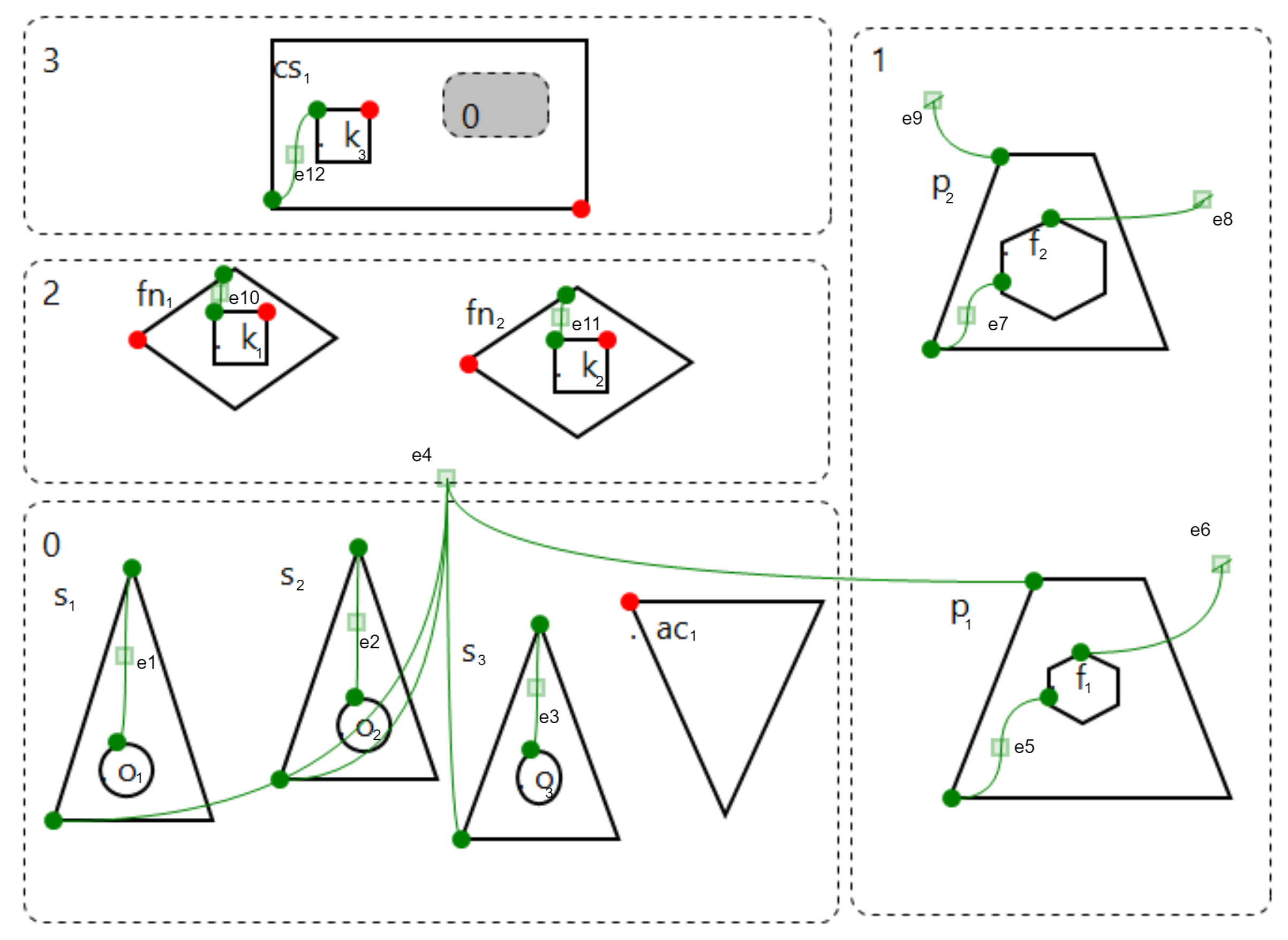
4.2. Physical Part Modelling

Definition 1.
Given a Fog system F, its physical structure B F is specified as:
B F = B , R , U , B 0 , F
with:
  • B is the set of bigraphs representing the fog system’s states, and each bigraph represents a given state of the fog system at some point.
  • R is the set of labelled reaction rules modelling the different possible transitions from a fog system state to another one. The set of labels is noted L .
  • U is the set of actions R × V B with V B the set of nodes of each bigraph B i B , and each action is related to a specific node belonging to V B .
  • B 0 represents the initial physical state of the fog system.
  • F is the transition function that the model uses to reach a new state.
Example 1
We return to the case of Luggage Inspection System (LIS). We illustrate the previous notations to define graphically the initial state B 0 of B F as shown in Figure 5. In addition, Table 2 and  Table 3 associate to each element of the physical part of the fog system the equivalent semantics in the bigraph model. The bigraph is composed of four regions. Each region represents a layer of the CLA4Fog. 0: IoT layer, 1: Communication layer, 2: Fog layer, and 3: Cloud layer.
Sorts are used to distinguish node types for structural purposes and constraints. For instance, some nodes must have a specific parent so that it is consistent with the fog paradigm, while controls identify states and parameters a node can have. We categorise the elements of LIS as follows: input devices’ interfaces are all of sort i; output ones are of sort k; captured data are of sort e; fog nodes are of sort f; communication protocols are of sort c; formats are of sort o; cloud services are of sort a; and instructions are of sort x.
The initial state of the system is modelled by a bigraph B 0 = ( V , E , c t r l , p r n t , l i n k ) : I J with V being the set of all the nodes; E is the set of all the hyperedges; the c t r l function represents the number of ports of each node; and the p r n t one associates to each node a parent node or a parent region (Figure 5). The link function connects each node port to a hyperedge. For example, e 1 is linked to the unique port of o 1 and to the second port of s 1 . I is the internal interface of B 0 〈 number of sites, set of inner names = 1 , , and J is the external interface 〈 number of regions, set of outer names = 4 , .
In our example, to ensure a correct bigraph construction of B , we have to add some formation rules Φ i ( i = 0 13 ), summarised in Table 4. These rules specify the structural constraints over the bigraphical part of the model. For instance, rule Φ 0 specifies that sensors host only captured data. Rule Φ 1 specifies that actuators host only instructions. Rules Φ 2 and Φ 3 specify that actions are made up only according to formatted captured data. Rules Φ 4 and Φ 6 express that fog nodes and cloud services host only actions or formatted captured data. In rule Φ 5 , we show that protocols produce the formats used to format the captured data. Rule Φ 7 states that a fog node or a cloud system are only responsible for producing an action. Rule Φ 8 states that a format is always linked to captured data. In rules Φ 9 Φ 12 , we structurally define the different layers of the fog system F. In rule Φ 13 , atomic nodes have no children.
The local behaviour expressing the dynamics of LIS is defined by a set of reaction rules R = R 1 , R 2 , . . . , R 14 summarised in Table 5. Possible local reaction rules that do not involve the virtual and intelligent part of the system (the agents) are classified according to their area of application.
The transition function that permits the transition from a state to another by associating a bigraph to an initial one and a control is defined in this example as follows: F ( B 0 , ( R 1 , s ) ) = B 1 ; F ( B 1 , ( R 2 , o ) ) = B 2 ; F ( B 2 , ( R 3 , f ) ) = B 3 ; F ( B 3 , ( R 4 , k ) ) = B 4 ; F ( B 4 , ( R 5 , a c ) ) = B 5 ; F ( B 3 , ( R 6 , k ) ) = B 6 ; F ( B 6 , ( R 7 , a c ) ) = B 7 ; F ( B 0 , ( R 8 , s ) ) = B 8 ; F ( B 8 , ( R 9 , o ) ) = B 9 ; F ( B 9 , ( R 10 , f ) ) = B 10 ; F ( B 10 , ( R 11 , o ) ) = B 11 ; F ( B 11 , ( R 12 , a c ) ) = B 12 ; F ( B 1 , ( R 13 , c l ) ) = B 13 ; F ( B 8 , ( R 14 , c l ) ) = B 13 .
For example, F ( B 0 , ( R 1 , s ) ) = B 1 expresses the transition from B 0 to B 1 with the execution of the control ( R 1 , s ) , which expresses the application of the reaction rule R 1 on the node s.
We notice at this modelling step of our approach that the system will not evolve as desired if we solely apply these rules without the involvement of the agents. In general, the structural evolution must be triggered by a virtual entity: agents. Each one observes and analyses its environment to orchestrate an efficient execution.
The physical structure B F of the BiAgents* model gives the opportunity to express different concepts of a Fog architecture. This formalism permits to model the hierarchical aspects of the CLA4Fog in addition to the modelling of its heterogeneous elements using the sorting discipline. Moreover, the distribution and links between these elements are well expressed using the l i n k and p r n t functions.

4.3. Virtual Part Modelling

In this section, we give the definition of the virtual part of the BiAgents*, which consists in a set of agents. Each agent may be in a given state at a time. Initially, it is at an “observation” state, then, it can evolve to an “analysis” state or a “migration” one. From the “analysis” state, the agent can pass to the state of “decision.” After being in the state of decision, it can return to the initial state “observation” or go to the state of “interaction” with other agents or apply an “action” in the structure of the system (trigger a reaction rule) as shown in Figure 6.
Definition 2.
The virtual part of a fog system F is defined by A F , which is a set of a i agents such that a i = ( O , o b s , h o s t , m g r t , a n , D , i n t , M , c t r , U ) where each element is responsible of the definition of an agent’s state:
  • Observation
    O is the set of the different system’s states (bigraphs) that the agent a i observes ( O B ).
    o b s is the function of observing a system’s state using the observed bigraph and a i host, o b s : B × V B O .
  • Migration
    h o s t is the host of the agent (a bigraphical node or region).
    m g r t is the function of migration. a i agent can move from any part of the system to another, and even though the layers m g r t : V B × O V B .
  • Analysis
    a n is the function of analysing an information a n : O × V B D .
  • Decision
    D is the set of decisions that the agent a i can take after an analysis ( D L ) with L the set of reaction rules labels.
  • Interaction
    i n t is the function of interaction between agents, using the receiver agent a A , the actual agent a i sends a message after analysis. i n t : A × D M a .
    M is the set of messages received by the agent a i
  • Action
    c t r is the application of a decision taken by an agent after analysis or reception of a message by another agent c t r : D M P ( U ) with P ( U ) the subsets set of U .
    U is the set of reaction rules that a i can apply according to a node of the current bigraph; it represents the set of actions that a i can do in a specific part of the system ( U U ) .
Example 2
In the LIS example, there are four types of agents: Sensor control, fog control, communication control, and cloud control. According to the specified fog system, there can be many instantiations of each type of agent to make each one focus on a specific task. The virtual part of the BiAgent* modelling the LIS example is A F = a s 1 , a s 2 , a s 3 , a F C , a I C o m , a E C o m , a C C : Three sensor agents, one fog control agent, two communication control agents, and one cloud control agent. The initial configuration of the considered system is materialised by: the different sensors containing captured data; the different formats relied to the protocols of communications and eventual actions generated in the fog nodes and cloud applications; and the multiple agents defined in the fog layer. The algebraic form of the fog system F modelling the LIS system focusing on its locality (i.e., place graph) is given by: F = def ((s1.o1)|(s2.o2)|(s3.o3)|ac1)‖(fn1.k1)|(fn2.k2)|as1|as2|as3|aFC|aICom|aECom|aCC)‖(p1.f1)|(p2.f2)‖(cs1.(k3|d0)).
We consider, for instance, the description of the agent a F C as follows:
a F C = ( O F C , o b s F C , h o s t F C , m g r t F C , a n F C , D F C , i n t F C , M F C , c t r F C , U F C )
  • O F C = B 3 , B 5 , B 7
  • o b s F C ( B 3 , 1 ) = o b s 1 , o b s F C ( B 5 , f 1 ) = o b s 2 , o b s F C ( B 7 , f 2 ) = o b s 3
  • h o s t F C = r e g i o n 1
  • m g r t F C ( r e g i o n 1 , o b s 1 ) = f 1 ; m g r t F C ( f 1 , o b s 2 ) = r e g i o n 1 ; m g r t F C ( f 2 , o b s 3 ) = r e g i o n 1
  • a n F C ( o b s 2 , f 1 ) = R 4 , a n F C ( o b s 3 , f 2 ) = R 6
  • D F C = { R 4 , R 6 }
  • i n t F C ( ) =
  • M F C = { “sending to Fog” }
  • c t r F C ( R 4 ) = { ( R 4 , k 1 ) , ( R 5 , a c 1 ) } ; c t r F C ( R 6 ) = { ( R 6 , k 2 ) , ( R 7 , a c 1 ) }
  • U F C = { ( R 4 , k 1 ) , ( R 5 , a c 1 ) , ( R 6 , k 2 ) , ( R 7 , a c 1 ) }
Considering the system LIS specified by a BiAgent* F = A F B F , its complex behaviour may be defined by observing a state in O with the function o b s , analysing its observation with the function an, taking a decision in D , communicating its decision with the function int by sending a message to another agent’s M , and triggering the adequate action in U at the right moment with the function c t r . It might migrate from a host to another with the function m g r t .
To deal with this BiAgents* complex behaviour, we have to define a new concept, extending the concept of a transition rule with these agents’ functions.

4.4. Smart Behaviour Modelling

We adopt the concept of BiAgents* traces and their projections in order to model the smart behaviour of a fog system. In this section, we will consider the example of LIS system.
A trace according to [26] is a sequence of bigraphs B 0 , B 1 , . . . such that for each B i and B i + 1 , there is a reaction rule B i B i + 1 . Traces provide the different events that happen in the considered system.
We note t = B 0 R 1 B 1 R 2 B 2 R 3 B 3 with R 1 , R 2 , and R 3 the reaction rules that allow the transition from a bigraph to another.
We represent the flow of agents in space through projection t a on the agent a of a trace t defined as follows:
t a = ( B i , h j a ) i n t a n o b s ( B i , h j a ) mgrt ( B i , h j + 1 a ) R ( B i + 1 , h j + 1 a ) . . .
where each B i is the bigraph that holds the host h i a . We notice that with the functions of observation ( o b s ), analysis ( a n ), and interaction ( i n t ), the couple ( B , h ) does not change, because neither the structure of the bigraph nor the host of the agent changes. Conversely, the functions of migration ( m g r t ) and a reaction rule (R) have an effect on this couple.
This study’s main contribution is to give a precise interpretation to the constituent elements of a trace (structures and behaviours) and their projections. The possible events that decorate a given projection are related to agent states (Figure 6). The projection of a trace on an agent inherits this extension by enriching these projections with the functions of analysis and interaction.
As shown in Table 6, each trace defines a fog system evolution that may involve one or more states B i B belonging to the physical structure B F . For instance, the trace t 3 indicated in Table 6 explains that, when captured data are sent to the internal protocol, the system formats this data and sends them to the fog layer. In the BiAgents* definition, the trace modelling of this behaviour implies three possible LIS states: B 1 : data are in the internal protocol; B 2 : data are formatted in internal protocol; and B 3 : data are in the corresponding fog node. The transition from one state to another is modelled by two reaction rules R 2 and R 3 .
More complex behaviour of LIS may be obtained by composing traces (operator “;”)—for example, the composed trace t 1 ; t 3 ; t 4 , to detect a dangerous bag in the area of luggage inspection.
The system executes the trace t 1 then t 3 and finally t 4 . This means that first, when data are captured ( B 0 ), the system sends it to the internal communication protocol ( R 1 ). Then, captured data are formatted ( R 2 ) and sent to fog ( R 3 ). Finally, the recognition system installed in the corresponding fog node triggers an action ( R 4 ) that displays an alert in the screens ( R 5 ). Similarly, other possible scenarios of LIS are as follows:
  • t 1 ; t 3 ; t 5 : detection of an abnormal number of bags/trays
  • t 1 ; t 8 : detection of hacking
  • t 2 : t 6 ; t 7 : data destined to analysis
  • t 2 ; t 9 : detection of hacking
Table 7 presents the different projections of the traces t 1 t 9 . We note that the functions host and int in our example are defined by:
i n t ( a , R 1 ) = ( “send to Fog” ) if a = a S 1 or a S 2 or a S 3 ;
i n t ( a , R 8 ) = ( “send to Cloud” ) if a = a S 1 or a S 2 or a S 3 ;
i n t ( a I C o m , R 2 ) = ( “sending to Fog” ) ; i n t ( a E C o m , R 9 ) = ( “sending to Cloud” ) .
h 0 ( a ) = r e g i o n 2 if a = a S 1 or a S 2 or a S 3 or a I C o m or a E C o m or a F C or a c c ;
h 1 ( a S 1 ) = o 1 ; h 2 ( a S 2 ) = o 2 ; h 3 ( a S 3 ) = o 3 ; h 4 ( a I C o m ) = f 1 ; h 5 ( a F C ) = f 1 or h 5 ( a F C ) = f 2 , h 6 ( a E C o m ) = f 2 ; h 7 ( a C C ) = k 1 or h 7 ( a C C ) = k 2 or h 7 ( a C C ) = k 3
For example, the projection of t 3 is as follows: The internal communication security control agent a I C o m observes the bigraph B 1 from the fog region and migrates to the format f 1 . This agent analyses the format and takes the decision to apply the reaction rule R 2 . This agent informs the fog control agent a F C about its decision. After this interaction, R 2 is applied followed by R 3 . When R 3 is applied, the system state becomes B 3 . a I C o m observes this bigraph and returns to its initial host, the fog region.

5. Execution and Formal Analysis

As far as we know, there exists no tool built around BiAgents that enables to deal with agents’ behaviour and actions. In this work, we opted to use a Maude language extension called the Maude strategy [12] to tackle this limitation and associate an executable model to BiAgents*. Thus, we defined the different aspects of the BiAgents* model in terms of the Maude strategy concepts.

5.1. Maude Strategy Presentation

Maude [27] is a high-level formal specification language based on equational and rewriting logics. A Maude program describes a logical theory, and its computation implements a logical inference based on the program’s axioms. A Maude module may be:
  • A functional module implements an equational theory in an extension of order-sorted equational logic called membership equational logic. This theory is mathematically described by a pair ( Σ , E A ), where Σ is the module’s signature that specifies the sorts, subsorts, kinds, and operators. E is the collection of equations (possibly conditional), and A is the set of equational attributes declared for some operators such as a s s o c for associative, c o m m for commutative, etc.
  • A system module that implements a rewrite theory as a triple ( Σ , E A , R ), where ( Σ , E A ) is the module’s membership equational theory part, and R is a collection of possibly conditional rewrite rules.
Example 3
We illustrate a simple problem using Maude. In this problem [28], a shepherd needs to carry to the other side of a river a wolf, a goat, and a cabbage. The shepherd has only one boat with two seats for himself and another traveller. The problem in this example is that, in the absence of the shepherd s, the wolf w would eat the goat g, and the goat would eat the cabbage c. Operation Initial refers to the initial situation, where it is assumed that all elements are located on the left side of the river through an equation. The rewrite rules represent how the wolf and goat eat and the different ways to cross the river. In this example, ( Σ R C , E R C A R C , R R C ) is defined as: Σ R C = (sorts as  Side , operations as  left : -> Side , and variables as  S : Side). E R C = equations as  eq change (left) = right. A R C = equational attributes as  assoc and comm. R R C = rewrites rules as  rl [ shepherd - alone ] : s (S) = > s (change (S)).
Futureinternet 14 00052 i001
The Maude language has been cited in many scientific articles and books. It has been used to formally specify and execute context-aware systems [29], cloud systems [30], supply chain management [31], and cyber-physical systems [32].
It is known that various extensions of Core Maude have been proposed such as HiMaude [33], to deal with hybrid systems, and RT Maude [34] for real-time systems.
Among these extensions, the Maude strategy extension [12] is a specific strategy language for Maude that aims to separate the rewrite rules R and their execution using strategies. The definition of the system module becomes ( Σ , E A , S ( R , S M ) ) with S the semantic describing the system’s behaviour. S is defined by: R (the collection of possibly conditional rewrite rules) and S M , the strategy module that is used to guide the rewrite process and the use of these rewrite rules that influences the system’s behaviour.
Due to the modular separation offered by this extension, we may provide several strategy modules for the same Maude system, with each module offering a specification of a separate execution track, allowing for greater versatility in terms of the various scenarios that can be asserted.
Example 4
To solve the shepherd problem [28], the first two equations of RIVER-CROSSING are used to force the Maude system to apply them before any rewrite rule. Apart from the fact that this solution introduces a coherence problem that had to be solved, it also changes the semantics of the problem. Another solution is to use three strategies defined in a strategy module. The eating strategy controls how to eat for the goat and wolf (controls the execution of the w o l f e a t s and g o a t e a t s rules). The o n e C r o s s strategy applies one of the other rules only once. Finally, the a l l C E strategy returns all accessible states. On the basis of the first definition ( Σ R C , E R C A R C , R R C ) , R R C is replaced by S ( R , S M ) where R = R R C and S M = strategies sortings as  strat eating : @ Group and strategies definitions as
Futureinternet 14 00052 i002

5.2. From BiAgents* to Maude Strategy

The defined BiAgents* specifications for the fog systems’ structure can be represented by a functional module, where the declared operations and equations define constructors that build the system’s elements (physical and virtual parts and their location) as shown in Table 8. Similarly, the specified BRS dynamics in addition to the agents’ functions describing the system’s behaviour can be specified by a system module. The different possible executions are described as conditional or non-conditional rewrite rules.
In addition, each defined trace in BiAgents* may be defined by strategies composition, as defined in a Maude strategy module. As mentioned in Section 4, each reaction rule or series of reaction rules are triggered by the analysis’ result of the appropriate agent. Table 8 depicts the transcription of the BiAgents* model into a Maude strategy specification. Each evolution of agents’ state is represented by a simple strategy as S 1 in Table 8. These strategies are a combination of sequential rewrite rules ( o b s e r v a t i o n , m i g r a t i o n , e t c . )
Example 5
In LIS, we define the BiAgents* model with three modules (Figure 7).
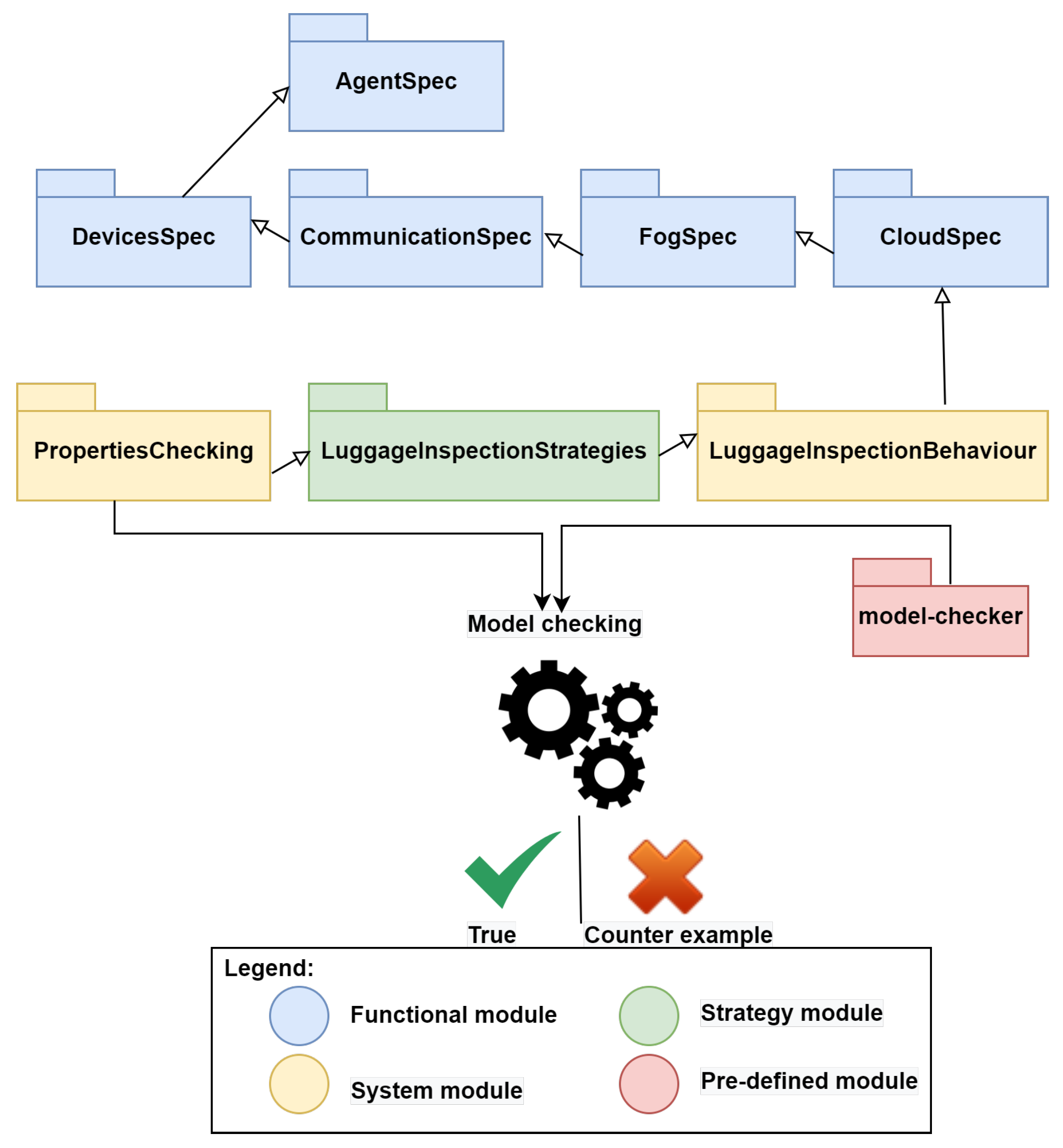
  • The functional module contains five sub modules according to the agents and the four regions of the bigraphical model, named: AgentSpec, DevicesSpec, CommunicationSpec, FogSpec, and CloudSpec.
  • The system module contains two sub modules named LuggageInspectionBehaviour and PropertiesChecking.
  • The strategy module is named LuggageInspectionStrategies.
The experiments were performed on a PC with an Intel(R) Core™ i7-8650U CPU @ 1.90 GHz 2.11 GHz, with 32 GB of internal memory, and running Windows 10, version 1903 18362.900 in an Oracle virtual machine virtual Box version 6.0.14 r133895 (Qt5.6.2) 2019 windows 7 with 16 GB of internal memory.
The proposed architecture is validated by the successful execution of the aforementioned system. Hence, given a starting state describing the architecture, the system always reaches the desired final state.
An example of execution of the aforementioned system using the Maude strategy tool is given by the following code
Futureinternet 14 00052 i003
The above code represents how the Maude strategy tool executes the system by starting with an observation of the sensor agent a S 1 and, after 62 rewrites, reaches to the final state, where an action is executed in the screens (to display an alert). We may notice, too, that there is a history of execution with the agent’s communications (fc and csc1 representing a F C and a I C o m , respectively).

5.3. Lis Formal Analysis

As shown in Figure 7, the next step after of our BiAgents* execution under the Maude strategy is a formal analysis of some relevant properties inherent to Fog systems, especially LIS. We chose, in this work, to develop a set of Linear Temporal Logic (LTL) propositional formulae that reflect the predicted model’s high-level strategies for the various layers of LIS. They characterise the system’s temporal evolution based on the evolution of the system’s symbolic states.
Defined formulae typically express the key qualities of liveness and safety, which may be used to assess behavioural correctness on a qualitative level. The key LTL symbols and operations that are used in this work are shown as follows (more information on LTL syntax and semantics are available in (Rozier, 2011): ∧ : Conjunction / and; ∨ : Disjunction / or; □ : Globally / always; ⋄ : Eventually.
Table 9 shows how the properties of portability of data and syntactical and semantic interoperability are interpreted in LIS and how they are expressed as LTL formulas using the predicated defined in Table 10.
As an example, the property of “ s e m a n t i c I n t e r o p e r a b i l i t y ” means that, always, data, formats, and actions related to it can be analysed by all the agents of the system.
The execution of the command
 reduce in PropertiesChecking : modelCheck(initial, portability, ’ST) 
gives a true result confirming the verification of portability property as for the execution of the same command with the properties of semantic and syntactic interoperability. These properties are checked to be true by the mean of the Maude strategy model-checker as given by the following code execution:
Futureinternet 14 00052 i004
These experimental results show the correctness of the proposed approach.

6. Related Work

In the literature, there have been various research studies dealing with connected objects environments such as fog computing, edge computing, and IoT. In this work, we only identify and analyse the approaches that are directly related to the fog infrastructure. Particularly, we cite some approaches that deal with the modelling of fog systems in the basis of various formalisms or notations, as illustrated in Table 11.
In the following, we address the approaches that deal with fog systems and their modelling based on different formalisms as illustrated in Table 11.
In [35], the authors proposed a framework that includes feature-based modelling to provide abstract models for expressing relations and restrictions between QoS properties of an IoT application, such as performance, security, and environmental conditions. The authors presented a lower-level modelling approach, based on the domain-specific language FAMILIAR, in which physical quantities were used to find measurable attributes that approximate QoS between modelled aspects. To find measurable associations between performance, security levels, and energy, they applied measurement-based models to generate a three-dimensional attribute space. They identified personalised health monitoring (PHM) as the key gap in the management of diverse devices in IoT systems, making this framework exclusive to these systems and not automatically adaptable to other IoT systems.
In [36], the authors modelled virtually the behaviour of a critical healthcare task management system using a multi-agents system (MAS). They used four types of agents: personal, master personal, fog node, and master fog nodes agents to manage critical tasks by prioritising and scheduling these ones. They simulated the behaviour of a critical healthcare system using iFogSim with real-world ECG datasets.
The authors of [37] proposed an adaptive approach for improving the processing time of tasks in fog–cloud systems using rule-based learning and case-based reasoning. They used scheduling algorithms in order to model virtually a fog system and express its behaviour using Uppaal timed automata. They improved the task-execution’s parameters by using some tasks randomly offloaded to the cloud and the fog. Using their results, they offloaded each remaining task to the nearest fog node or to the cloud when the latter is not free. They simulated this execution using iFogSim and verified their proposition using the Uppaal model checker.
The authors of [38] modelled a Hybrid-Cloud–Fog system (HFC) using the formal language: performance evaluation process algebra (PEPA). With the help of the PEPA compositional model, they specified the physical composition of fog systems. They designed the virtual management of this type of system using a PEPA scheduling scheme. PEPA helps in the modelling of large-scale systems because of its characteristics of compositionality and abstraction. They evaluated the performance of their framework by stochastic simulation and fluid flow analysis.
In [39], the authors proposed an authentication scheme based on an extension of a real-or-random (ROR) model for fog computing systems. The authors offered a lightweight and secure model. They verified the security of the model proposed through an analysis using formal (ROR) and informal security analysis. The model proved to be secure and lightweight. However, this approach does not show well the behaviour of the system through a simulation.
In [40], the authors modelled a self-adaptive fog system using the formal modelling approach of Bigraphical Reactive Systems (BRS). They modelled a fog system’s structure and behaviour with axiomatic construction rules to describe the physical distribution of a fog system’s elements and reaction rules to model their evolution. They also considered the formal verification of the behaviour’s correctness.
The authors of [43] considered different security protocols used in fog and IoT networks for data security. They used High-Level Petri Net (HLPN) for modelling physically and behaviourally their system and a Z3 constraints solver for an automated satisfiability modulo theories (SMT) solution and formal verification. They picked the Shibboleth security protocol after its analysis in the cloud–IoT environment. Considering the substantiality of this protocol’s properties, the authors added new layers of Shibboleth among clients and fog nodes. Their purpose was to make authentication, authorisation, user’s privacy, and data access secure from Service Providers (SP).
In [41], the authors proposed a fog architecture for a fog system, an oil and gas refinery plant. They used Bigraphs to model the physical view of this system and control agents for the virtual view. The behaviour of this system was studied through bigraphical reaction rules and control agents’ behaviour; the resulting model was simulated using a Maude-based tool for specified CA-BRS. They used Bigraphs and agents to model a specified fog system.
In [42], the authors modelled a fog system focusing on the orchestration of the resources aspect using the rewrite logic-based Maude language. They came up with a set of monitoring predicates and atomic adaptive operations. The predicates were applied to determine the resource provisioning situations of both levels. The operations were employed to determine which adaptation mechanisms should be used. They also specified a set of temporal properties that needed to be met in order to analyse the orchestrator’s behaviours and assure their quality.
As mentioned in Table 11, our work aimed to facilitate the development of a complex system such as a fog one, by giving a generic fog architecture and a formal and executable model dealing with the different aspects (physical, virtual management, and behaviour), which characterise a smart fog system.
However, the resort to the BiAgents* formalism with its concept of trace and projections, which are purely mathematical, shows a certain complexity in the understanding of the proposed model and its analysis. Thus, its use is intended for experts. To overcome this limitation, a practical environment simplifying the use of BiAgents* is possible.

7. Conclusions

In this study, we defined a BiAgents*-based model of fog systems in an incremental manner, starting with a cross-layered architecture proposition (CLA4Fog) that identifies various views through some layers: physical, virtual, and interactional ones.
In addition, we refined the definition of BiAgents* proposed by [9] to model these different aspects of a fog system. Indeed, bigraphs are a suitable framework supporting the hierarchical and modular description of fog systems. The smart aspect of the BiAgents* model, represented by the agents set is able to observe, analyse, interact, migrate, and trigger actions on the physical model. To guide the smart evolution of the model, we used bigraphical traces and their projections on agents. Further, we used the Maude strategy tool to execute and analyse the proposed model. Furthermore, we expressed properties of portability and semantic and syntactic interoperability with Linear Temporal Logic (LTL). Then, we checked them using the Maude strategy model checker tool through a case study of a Luggage Inspection System (LIS) in an airport terminal.
In the future, we plan to analyse some quantitative properties related to fog systems QoS. Besides, we aim to propose an extension of the proposed model to take into account the time constraints in fog systems.

Author Contributions

Conceptualization, F.B.; Formal analysis, S.M.; Investigation, S.M.; Methodology, S.M. and F.B.; Project administration, F.B. and N.H.; Supervision, F.B. and N.H.; Validation, S.M.; Writing—original draft, S.M.; Writing—review & editing, F.B. and N.H. All authors have read and agreed to the published version of the manuscript.

Funding

This research received no external funding.

Data Availability Statement

Not applicable, the study does not report any data.

Conflicts of Interest

The authors declare no conflict of interest.

References

  1. IEEE Standard 1934–2018; IEEE Standard for Adoption of OpenFog Reference Architecture for Fog Computing. IEEE: Manhattan, NY, USA, 2018. [CrossRef]
  2. Ai, Y.; Peng, M.; Zhang, K. Edge computing technologies for Internet of Things: A primer. Digit. Commun. Netw. 2018, 4, 77–86. [Google Scholar] [CrossRef]
  3. Yi, S.; Hao, Z.; Qin, Z.; Li, Q. Fog computing: Platform and applications. In Proceedings of the 2015 Third IEEE Workshop on Hot Topics in Web Systems and Technologies (HotWeb), Washington, DC, USA, 12–13 November 2015; pp. 73–78. [Google Scholar]
  4. Mouradian, C.; Naboulsi, D.; Yangui, S.; Glitho, R.H.; Morrow, M.J.; Polakos, P.A. A comprehensive survey on fog computing: State-of-the-art and research challenges. IEEE Commun. Surv. Tutor. 2017, 20, 416–464. [Google Scholar] [CrossRef] [Green Version]
  5. Asadi, M.; Fathy, M.; Mahini, H.; Rahmani, A.M. An Evolutionary Game Approach to Safety-Aware Speed Recommendation in Fog/Cloud-Based Intelligent Transportation Systems. IEEE Trans. Intell. Transp. Syst. 2021, 1–10. [Google Scholar] [CrossRef]
  6. Xiao, Y.; Krunz, M. AdaptiveFog: A Modelling and Optimization Framework for Fog Computing in Intelligent Transportation Systems. IEEE Trans. Mob. Comput. 2021. [Google Scholar] [CrossRef]
  7. Roig, P.J.; Alcaraz, S.; Gilly, K.; Juiz, C. Modelling a Plain N-Hypercube Topology for Migration in Fog Computing. In Advances in Computing and Network Communications; Thampi, S.M., Gelenbe, E., Atiquzzaman, M., Chaudhary, V., Li, K.C., Eds.; Springer: Singapore, 2021; pp. 595–608. [Google Scholar]
  8. Abd Elaziz, M.; Abualigah, L.; Ibrahim, R.A.; Attiya, I. IoT Workflow Scheduling Using Intelligent Arithmetic Optimization Algorithm in Fog Computing. Comput. Intell. Neurosci. 2021, 2021, 9114113. [Google Scholar] [CrossRef] [PubMed]
  9. Souad, M.; Faiza, B.; Nabil, H. Formal Modeling IoT Systems on the Basis of BiAgents* and Maude. In Proceedings of the 2020 International Conference on Advanced Aspects of Software Engineering (ICAASE), Constantine, Algeria, 28–30 November 2020; pp. 1–7. [Google Scholar]
  10. Milner, R. The Space and Motion of Communicating Agents; Cambridge University Press: Cambridge, UK, 2009. [Google Scholar]
  11. Pereira, E.; Kirsch, C.; Sengupta, R. Biagentsa bigraphical agent model for structure-aware computation. Cyber-Phys. Cloud Comput. Work. Pap. CPCC Berkeley 2012, 1–13. Available online: http://cpcc.berkeley.edu/papers/paperBiagents12.pdf (accessed on 12 January 2022).
  12. Eker, S.; Martí-Oliet, N.; Meseguer, J.; Verdejo, A. Deduction, strategies, and rewriting. Electron. Notes Theor. Comput. Sci. 2007, 174, 3–25. [Google Scholar] [CrossRef] [Green Version]
  13. McKendrick, J. Fog Computing: A New IoT Architecture? 2016. Available online: https://www.rtinsights.com/what-is-fog-computing-open-consortium (accessed on 12 January 2022).
  14. Iorga, M.; Feldman, L.; Barton, R.; Martin, M.J.; Goren, N.S.; Mahmoudi, C. Fog Computing Conceptual Model; NIST SP, National Institute of Standards and Technology: Gaithersburg, MD, USA, 2018. [Google Scholar]
  15. Kapsalis, A.; Kasnesis, P.; Venieris, I.S.; Kaklamani, D.I.; Patrikakis, C.Z. A cooperative fog approach for effective workload balancing. IEEE Cloud Comput. 2017, 4, 36–45. [Google Scholar] [CrossRef]
  16. Moreno-Vozmediano, R.; Montero, R.S.; Huedo, E.; Llorente, I.M. Cross-site virtual network in cloud and fog computing. IEEE Cloud Comput. 2017, 4, 46–53. [Google Scholar] [CrossRef] [Green Version]
  17. Bouheroum, A.; Benzadri, Z.; Belala, F. Towards a formal approach based on bigraphs for fog security: Case of oil and gas refinery plant. In Proceedings of the 2019 7th International Conference on Future Internet of Things and Cloud (FiCloud), Istanbul, Turkey, 26–28 August 2019; pp. 64–71. [Google Scholar]
  18. Marir, S.; Belala, F.; Hameurlain, N. A formal model for interaction specification and analysis in IoT applications. In Proceedings of the International Conference on Model and Data Engineering, Marrakesh, Morocco, 24–26 October 2018; pp. 371–384. [Google Scholar]
  19. Sales, M. The Air Logistics Handbook: Air Freight and the Global Supply Chain; Routledge: London, UK, 2013. [Google Scholar]
  20. da Rocha, H.; Espirito-Santo, A.; Abrishambaf, R. Semantic interoperability in the industry 4.0 using the IEEE 1451 standard. In Proceedings of the IECON 2020 the 46th Annual Conference of the IEEE Industrial Electronics Society, Singapore, 18 November 2020; pp. 5243–5248. [Google Scholar]
  21. Petcu, D.; Vasilakos, A.V. Portability in clouds: Approaches and research opportunities. Scalable Comput. Pract. Exp. 2014, 15, 251–270. [Google Scholar] [CrossRef] [Green Version]
  22. Damgaard, T.C.; Birkedal, L. Axiomatizing binding bigraphs. Nord. J. Comput. 2006, 13, 58. [Google Scholar]
  23. Krivine, J.; Milner, R.; Troina, A. Stochastic bigraphs. Electron. Notes Theor. Comput. Sci. 2008, 218, 73–96. [Google Scholar] [CrossRef] [Green Version]
  24. Sevegnani, M.; Calder, M. BigraphER: Rewriting and analysis engine for bigraphs. In Proceedings of the International Conference on Computer Aided Verification, Toronto, ON, Canada, 17–23 July 2016; pp. 494–501. [Google Scholar]
  25. Grohmann, D.; Miculan, M. Directed bigraphs. Electron. Notes Theor. Comput. Sci. 2007, 173, 121–137. [Google Scholar] [CrossRef] [Green Version]
  26. Perrone, G.; Debois, S.; Hildebrandt, T. Bigraphical refinement. arXiv 2011, arXiv:1106.4091. [Google Scholar] [CrossRef] [Green Version]
  27. Clavel, M.; Durán, F.; Eker, S.; Lincoln, P.; Martı-Oliet, N.; Meseguer, J.; Talcott, C. Maude Manual (Version 2.1); SRI International: Menlo Park, CA, USA, 2005. [Google Scholar]
  28. Martí-Oliet, N.; Meseguer, J.; Verdejo, A. A rewriting semantics for Maude strategies. Electron. Notes Theor. Comput. Sci. 2009, 238, 227–247. [Google Scholar] [CrossRef] [Green Version]
  29. Cherfia, T.A.; Belala, F. Bigraphical reactive systems based approaches for modeling context-aware systems. Int. J. Adapt. Resilient Auton. Syst. (IJARAS) 2014, 5, 1–19. [Google Scholar] [CrossRef] [Green Version]
  30. Khebbeb, K.; Hameurlain, N.; Belala, F. Formalizing and simulating cross-layer elasticity strategies in Cloud systems. Clust. Comput. 2020, 23, 1603–1631. [Google Scholar] [CrossRef]
  31. Laouadi, M.A.; Mokhati, F.; Seridi-Bouchelaghem, H. A formal framework for organization-centered multi-agent system specification: A rewriting logic based approach. Multiagent Grid Syst. 2017, 13, 395–419. [Google Scholar] [CrossRef]
  32. Metelo, A.; Braga, C.; Brandão, D. Towards the modular specification and validation of cyber-physical systems. In Proceedings of the International Conference on Computational Science and Its Applications, Melbourne, Australia, 2–5 July 2018; pp. 80–95. [Google Scholar]
  33. Fadlisyah, M.; Ölveczky, P.C. The HI-Maude tool. In Proceedings of the International Conference on Algebra and Coalgebra in Computer Science, Warsaw, Polan, 3–6 September 2013; pp. 322–327. [Google Scholar]
  34. Ölveczky, P.C. Real-Time Maude 2.3 Manual. Research Report. 2004. Available online: http://urn.nb.no/URN:NBN:no-35645 (accessed on 12 January 2022).
  35. Venckauskas, A.; Stuikys, V.; Damasevicius, R.; Jusas, N. Modelling of Internet of Things units for estimating security-energy-performance relationships for quality of service and environment awareness. Secur. Commun. Netw. 2016, 9, 3324–3339. [Google Scholar] [CrossRef]
  36. Mutlag, A.A.; Ghani, M.K.A.; Mohammed, M.A.; Lakhan, A.; Mohd, O.; Abdulkareem, K.H.; Garcia-Zapirain, B. Multi-Agent Systems in Fog–Cloud Computing for Critical Healthcare Task Management Model (CHTM) Used for ECG Monitoring. Sensors 2021, 21, 6923. [Google Scholar] [CrossRef] [PubMed]
  37. Murtaza, F.; Akhunzada, A.; ul Islam, S.; Boudjadar, J.; Buyya, R. QoS-aware service provisioning in fog computing. J. Netw. Comput. Appl. 2020, 165, 102674. [Google Scholar] [CrossRef]
  38. Chen, X.; Ding, J.; Lu, Z.; Zhan, T. An Efficient Formal Modeling Framework for Hybrid Cloud-Fog Systems. IEEE Trans. Netw. Sci. Eng. 2020, 8, 447–462. [Google Scholar] [CrossRef]
  39. Guo, Y.; Zhang, Z.; Guo, Y. Fog-centric authenticated key agreement scheme without trusted parties. IEEE Syst. J. 2020, 15, 5057–5066. [Google Scholar] [CrossRef]
  40. Sahli, H.; Ledoux, T.; Rutten, É. Modeling self-adaptive fog systems using bigraphs. In Proceedings of the International Conference on Software Engineering and Formal Methods, Oslo, Norway, 16–20 September 2019; pp. 252–268. [Google Scholar]
  41. Benzadri, Z.; Bouheroum, A.; Belala, F. A Formal Framework for Secure Fog Architectures: Application to Guarantee Reliability and Availability. Int. J. Organ. Collect. Intell. (IJOCI) 2021, 11, 51–74. [Google Scholar] [CrossRef]
  42. Khebbeb, K.; Hameurlain, N.; Belala, F. A maude-based rewriting approach to model and verify cloud/fog self-adaptation and orchestration. J. Syst. Archit. 2020, 110, 101821. [Google Scholar] [CrossRef]
  43. Zahra, S.; Alam, M.; Javaid, Q.; Wahid, A.; Javaid, N.; Malik, S.U.R.; Khan, M.K. Fog computing over IoT: A secure deployment and formal verification. IEEE Access 2017, 5, 27132–27144. [Google Scholar] [CrossRef]
Figure 1. Specification and analysis of fog systems: our approach.
Futureinternet 14 00052 g001
Figure 2. Cross-layered architecture for fog systems (CLA4Fog).
Futureinternet 14 00052 g002
Figure 3. Generic configuration of an airport and its areas of surveillance.
Futureinternet 14 00052 g003
Figure 4. A bigraph anatomy.
Futureinternet 14 00052 g004
Figure 5. B 0 : The initial bigraph of the LIS physical part model B F .
Futureinternet 14 00052 g005
Figure 6. Agent’s possible states.
Futureinternet 14 00052 g006
Figure 7. LIS modules under Maude strategy.
Futureinternet 14 00052 g007
Table 1. CLA4Fog for LIS.
LayerIoTCommunicationFogCloud
Entities
Physical• Bar-code scanner
• Bags scanner
• Camera
• Screens
• Internal protocols
• External protocols
• Alert system
• Recognition system
• Analysis and storage cloud service
Virtual//Agents:
a S 1 , a S 2 , a S 3 , a I C o m ,
a E C o m , a F C , a C C
/
Interactions• Bar-code scanner and internal protocols
• Bags scanner and internal protocols
• Camera and internal protocols
• Bar-code scanner and external protocols
• Bags scanner and External protocols
• Camera and external protocols
• Internal protocols and alert system
• Internal protocols and recognition system
• External protocols and analysis and storage cloud service
• Alert system and screens
• Recognition system and screens
a S 1 and a F C
a S 1 and a F C
a S 1 and a F C
a S 1 and a F C
a S 1 and a F C
a S 1 and a F C
• Analysis and storage Cloud service and screens
Table 2. CLA4Fog and BiAgents* correspondences.
CLA4FogBiAgents* Specification
IoT layerRegion 0
• Physical view: sensors, actuators, etc.
• Interactional view: connexions with communication layer
• Place graph
• Link graph
Communication layerRegion 1
• Physical view: protocols, etc.
• Interactional view: connexions with fog layer and cloud layer
• Place graph
• Link graph
Fog layerRegion 2
• Physical view: Fog nodes, routers, etc.
• Virtual view: agents, process, etc.
• Interactional view: connexions with the other layers and
communications between agents
• Place graph
• Agents (observe, analyse
control, migrate)
• Link graph
and agents (interaction)
Cloud layerRegion 3
• Physical view: Cloud systems, apps, etc.
• Interactional view: Connexions with the other layers
• Place graph
• Link graph
Table 3. Sorting discipline associated to B F .
LIS ElementAritySort
IoT layer (region 0)
Bags scanner2i
Bar-code scanner2i
Camera2i
Screen1k
Captured data2e
Fog layer (region 1)
Alert system2f
Recognition system2f
Communication layer (region 2)
Internal communication protocol2c
External communication protocol2c
Data formats2o
Cloud layer (region 3)
Cloud services2a
Instructions1x
Table 4. Formation rules Φ for B F .
RuleDescription
Φ 0 All children of i nodes have sort e
Φ 1 All children of k nodes have sort x
Φ 2 All children of x nodes have sort o
Φ 3 All children of o nodes have sort e
Φ 4 All children of f nodes have sort o x ^
Φ 5 All children of c nodes have sort o e ^
Φ 6 All children of a nodes have sort o x ^
Φ 7 In an x node, one port may be linked to a f a ^ node
Φ 8 In an o node one port is always linked to an e node, and the other may be linked to a f x a ^ node
Φ 9 All children of a 0-region have sort in { i , k }
Φ 10 All children of a 1-region have sort c
Φ 11 All children of a 2-region have sort f
Φ 12 All children of a 3-region have sort a
Φ 13 All e nodes are atomic
Table 5. Reaction rules of B F associated to LIS.
LayersRule DescriptionAlgebraic Form
IoT → CommunicationSend data to internal protocol R 1   = def ((s.o)|id‖(p1.f1)|(p2.f2)|id)→(s|id)‖(p1.(f1|o))|(p2.f2)|id
Send data to external protocol R 8   = def ((s.o)|id‖(p1.f1)|(p2.f2)|id)→(s|id)‖(p1.f1)|(p2.(f2|o))|id
CommunicationDelete data from internal protocol R 13   = def (s|id)‖(p1.(f1|o))|(p2.f2)|id→(s|id)‖(p1.f1)|(p2.f2)|id
Delete data from external protocol R 14   = def (s|id)‖(p1.f1)|(p2.(f2|o))|id→(s|id)‖(p1.f1)|(p2.f2)|id
Format data according to internal communication protocol R 2   = def (p1.(f1|o))|(p2.f2)|id→(p1.(f1.o))|(p2.f2)|id
Format data according to external communication protocol R 9   = def (p1.f1)|(p2.(f2|o))|id→(p1.f1)|(p2.(f2.o))|id
Communication → FogSend formatted data to fog layer R 3   = def (p1.(f1.o))|id‖(fn1.k1)|(fn2.k2)|idp1|id‖(fn1.k1)|(fn2.k2)|(f1.o)|id
FogCreate instruction in the recognition system R 4   = def (fn1.k1)|(fn2.k2)|(f1.o)|id→(fn1.(k1.(f1.o)))|(fn2.k2)|id
Create instruction in the alert system R 6   = def (fn1.k1)|(fn2.k2)|(f1.o)|id→(fn1.k1)|(fn2.(k2.(f1.o)))|id
Fog → IoTSend instruction from the recognition system to the actuator R 5   = def ac1|idfn1.(k1.(f1.o)))|(fn2.k2)|id→(ac1.(k1.(f1.o)))|idfn1|(fn2.k2)|id
Send instruction from the alert system to the actuator R 7   = def ac1|id‖(fn1.k1)|(fn2.(k2.(f1.o)))|id→(ac1.(k2.(f1.o)))|id‖(fn1.k1)|fn2|id
Communication → CloudSend formatted data to the cloud layer R 10   = def (p2.(f2.o))|id‖(cs1.(k3|d1))|idp2|id‖(cs1.(k3|d1)|(f2.o))|id
CloudCreate instruction in the analysis and storage system R 11   = def (cs1.(k3|d1)|(f2.o))|id→(cs1.((k3.(f2.o))|d1))|id
Cloud → IoTSend instruction from the cloud to the actuator R 12   = def ac1|id‖(cs1.((k3.(f2.o))|d1))|id→(ac1.(k3.(f2.o)))|id‖(cs1.d1)|id
Table 6. Possible traces modelling the LIS behaviour.
Possible LIS BehaviourTrace Definition
Send data to internal communication protocol t 1 = B 0 R 1 B 1
Send data to external communication protocol t 2 = B 0 R 8 B 8
Treatment of captured data destined to fog nodes t 3 = B 1 R 2 B 2 R 3 B 3
Trigger action according to the recognition system t 4 = B 3 R 4 B 4 R 5 B 5
Trigger action according to the alert system t 5 = B 3 R 6 B 6 R 7 B 7
Treatment of captured data destined to cloud systems t 6 = B 8 R 9 B 9 R 10 B 10
Trigger action according to the analysis system t 7 = B 10 R 11 B 11 R 12 B 12
Detection of hacking the fog nodes t 8 = B 1 R 13 B 13
Detection of hacking the cloud systems t 9 = B 8 R 14 B 13
Table 7. Traces projections examples.
Traces Projections on Agents
t 1 Projection on a s 1 , a s 2 , a s 3
( B 0 , h 0 ) obs ( B 0 , h 0 ) mgrt ( B 0 , h ) an ( B 0 , h ) int 1 ( B 0 , h ) R 1 ( B 1 , h ) obs ( B 1 , h ) mgrt ( B 1 , h 0 )
( h = h 1 or h 2 or h 3 )
t 2 Projection on a s 1 , a s 2 , a s 3
( B 0 , h 0 ) obs ( B 0 , h 0 ) mgrt ( B 0 , h ) an ( B 0 , h ) int 2 ( B 0 , h ) R 8 ( B 1 , h ) obs ( B 1 , h ) mgrt ( B 8 , h 0 )
t 3 Projection on a I C o m
( B 1 , h 0 ) obs ( B 1 , h 0 ) mgrt ( B 1 , h 4 ) an 2 ( B 1 , h 4 ) int 3 ( B 1 , h 4 ) R 2 ( B 2 , h 4 ) R 3 ( B 3 , h 4 ) obs ( B 3 , h 4 ) mgrt ( B 3 , h 0 )
t 8 Projectionon a I C o m
( B 1 , h 0 ) obs ( B 1 , h 0 ) mgrt ( B 1 , h 4 ) an 2 ( B 1 , h 4 ) R 13 ( B 13 , h 4 ) obs ( B 13 , h 4 ) mgrt ( B 13 , h 0 )
t 4 Projection on a F C
( B 3 , h 0 ) obs ( B 3 , h 0 ) mgrt ( B 3 , h 5 ) an 3 ( B 3 , h 5 ) R 4 ( B 4 , h 5 ) R 5 ( B 5 , h 5 ) obs ( B 5 , h 5 ) mgrt ( B 5 , h 0 )
t 5 Projection on a F C
( B 3 , h 0 ) obs ( B 3 , h 0 ) mgrt ( B 3 , h 5 ) an 3 ( B 3 , h 5 ) R 6 ( B 6 , h 5 ) R 7 ( B 7 , h 5 ) obs ( B 7 , h 5 ) mgrt ( B 7 , h 0 )
t 6 Projection on a E C o m
( B 8 , h 0 ) obs ( B 8 , h 0 ) mgrt ( B 8 , h 6 ) an 4 ( B 8 , h 6 ) int 4 ( B 8 , h 6 ) R 9 ( B 9 , h 6 ) R 10 ( B 10 , h 6 ) obs ( B 10 , h 6 ) mgrt ( B 10 , h 0 )
t 9 Projection on a E C o m
( B 8 , h 0 ) obs ( B 8 , h 0 ) mgrt ( B 8 , h 6 ) an 4 ( B 8 , h 6 ) R 14 ( B 13 , h 6 ) obs ( B 13 , h 6 ) mgrt ( B 13 , h 0 )
t 7 Projection on a C C
( B 10 , h 0 ) obs ( B 10 , h 0 ) mgrt ( B 10 , h 7 ) R 11 ( B 11 , h 7 ) R 12 ( B 12 , h 7 ) obs ( B 12 , h 7 ) mgrt ( B 12 , h 0 )
Table 8. From BiAgents* to Maude strategy.
BiAgents* ModelMaude Strategy Specification
Physical Structure
Sorting disciplinesorts Agent Sensor Actuator Action DLayer ComLayer Protocol Flayer ClLayer.
Reaction rulesConditional rewrite rules of the form:
crl [rewrite-rule-name] : term = > term’ if condition.
Rewrite rules of the form:
rl [rewrite-rule-name] : term = > term’
Parent functionOperation of the form:
op parent [_,_] : Parent Child > Parent.
Virtual Structure
Agents’ behaviourop observe (_,_) : Nat Host > System.
op analyse (_,_) : Nat Data > Bool.
op interaction (_,_,_) : Nat Nat String > System.
op mgrt(_,_,_) : Nat Host Host > System.
crl [action] : term = > term’ if decision.
Smart behaviour Traces
Global TracesComposed Strategy with operators(| ; ...)
strat ST @ System.
sd ST : = (ST1 | ST2 | ... | ST9) *.
ProjectionsDefined Simple Strategies
strat ST1 @ System.
strat S1 @ System.
...
ST1 : = (S1 ; S11 ; S41 ; S411).
S1 : = (observation1 ; migration1).
...
Table 9. Some LIS properties.
PropertyCommentsLTL Definition
Portability of dataCaptured data must have the ability to move through the different elements of the system p o r t a b i l i t y = ( q 1 q 2 q 3 q 4 q 5 q 6 )
Syntactical InteroperabilityData must be formatted after capture and this format must be understandable by the treatment nodes of the system and actuators. s y n t a c t i c a l I n t e r o p e r a b i l i t y = ( ( b 1 b 2 b 3 ) b 4 )
Semantic interoperabilityAny transmitted information in many types of systems and sub systems must be a meaningful information (a meaningful information is an information that can be analysed by an agent s e m a n t i c I n t e r o p e r a b i l i t y = ( a 1 a 2 a 3 a 4 a 5 a 6 a 7 )
Table 10. Predicates definition.
PredicateDefinition
q 1 Data are hosted in a sensor
q 2 Data are hosted in a communication protocol
q 3 Data are hosted in the alert fog node
q 4 Data are hosted in the recognition fog node
q 5 Data are hosted in a cloud system
q 6 Data are hosted in an actuator
b 1 Format is hosted in alert fog node’s action
b 2 Format is hosted in recognition fog node’s action
b 3 Format is hosted in cloud system’s action
b 4 Format is hosted in action that is hosted in actuator
a 1 Sensor agent 1 analyses information
a 2 Sensor agent 2 analyses information
a 3 Sensor agent 3 analyses information
a 4 Internal communication security control agent analyses format of information
a 5 External communication security control agent analyses format of information
a 6 Fog control agent analyses information
a 7 Cloud control agent analyses information
Table 11. Fog systems formal modelling approaches.
ApproachesFormalismModellingSimulation/
Analysis
Genericity
PhysicalVirtualBehavioural
Venckauskas et al., 2016 [35]FAMILIAR DSLSPLOT
Mutlag et al., 2021 [36]Multi-agents systemiFogSim
Murtaza et al., 2020 [37]Timed
automata
iFogSim/
UPPAL Model checker
Chen et al., 2020 [38]Process algebra
(PEPA)
Stochastic simulation
Guo et al., 2020 [39]Process algebra
(ROR)
ROR
Sahli et al., 2019 [40]BRS
Benzadri et al., 2021 [41]CA-BRSMaude
Khebbeb et al., 2020 [42]Rewriting logicMaude
Zahra et al., 2017 [43]High-level petri netsZ3 for SMT
This workBiAgents*Maude strategy
Publisher’s Note: MDPI stays neutral with regard to jurisdictional claims in published maps and institutional affiliations.

