Article

Unreachable Peers Communication Scheme in Decentralized Networks Based on Peer-to-Peer Overlay Approaches

1
National Engineering Laboratory for Computer Virus Prevention and Control Technology, Tianjin 300384, China
2
Key Laboratory of Computer Vision and System, Ministry of Education, Tianjin 300384, China
3
Tianjin Key Laboratory of Intelligence Computing and Novel Software Technology, Ministry of Education, Tianjin 300384, China
4
Engineering Research Center of Learning-Based Intelligent System, Ministry of Education, Tianjin 300384, China
5
School of Computer Science and Engineering, Tianjin University of Technology, Tianjin 300384, China
*
Author to whom correspondence should be addressed.
Future Internet 2022, 14(10), 290; https://doi.org/10.3390/fi14100290
Submission received: 8 September 2022 / Revised: 8 October 2022 / Accepted: 9 October 2022 / Published: 12 October 2022
(This article belongs to the Special Issue Future Communication Networks for the Internet of Things (IoT))

Abstract

:
Decentralized networks bring us many benefits, but as networks evolve, many nodes either actively or passively become unreachable behind an NAT or a firewall. This has become a hindrance to the development of decentralized networks, where peer-to-peer communication data transfer between unreachable nodes cannot be accomplished, whether in decentralized file systems, decentralized social, or decentralized IoT. The existing scheme requires a series of centralized servers or requires network-wide flooding for consensus data, which can lead to the loss of decentralized nature of the network and cause flooding bottlenecks, contrary to the design concept of decentralization. In this paper, our proposed scheme uses a structured P2P overlay network to store the indexes of unreachable nodes in the whole network, so that the characteristics of a decentralized network are still maintained while ensuring the efficiency of lookup. When nodes communicate, the transmission channel is established so that both nodes continuously transmit data streams peer-to-peer without relying on the central server. Moreover, the scheme guarantees the security and privacy of nodes’ data transmission and the P2P overlay network without relying on centralized trusted institutions. Finally, we deploy a real cluster environment to verify the effectiveness of each module at different network sizes and prove the overall feasibility of the scheme. The scheme has certain advantages over existing solutions in terms of security, privacy, communication efficiency, device democracy, etc.

1. Introduction

The original design of the Internet (the underlying protocol) was decentralized, which greatly ensured the stability, fault tolerance and security of the network [1,2]. Despite the initial design principles, as the Internet evolved, there was a gradual move towards a single centralized point of access. This is because a centralized approach is the easiest way to achieve the target functionality and at the same time facilitate management (e.g., Twitter, Facebook, WhatsAPP, Google Drive), but some of the problems associated with centralization, single point of failure [3], certificate leaks [4,5], leaked files [6], centralized social networking privacy disclosure [7], smart camera leaks privacy [8] etc. cannot be well solved. This has led many researchers to explore decentralized networks, for example, the early emergence of P2P networks such as Bittorrent [9] and Napster [10] represent this series of attempts to decentralise about file sharing. The emergence of cryptocurrencies such as Bitcoin [11] and Ethereum [12], using blockchain technology that allows peer-to-peer communication to be de-trusted. These have contributed to a process of “re-decentralization”, which has seen the emergence of many decentralized applications, such as decentralized data trading [13,14,15] and decentralized social networking [16,17]. They have benefits that are difficult to achieve with centralized networks, such as no single point of failure, no centralized authority, and privacy protection.
However, with the development of the network, the shortage of IPv4 addresses [18,19], the slow transition to IPv6 and other issues [20,21], there are many nodes that are either actively or passively behind NAT or firewall and become externally unavailable for an active connection. Because NAT protocol [22] was originally designed to solve the IPv4 address reuse problem under the traditional centralized network represented by the C/S model, they could only be initiated by clients who could not connect directly from the outside. This causes a lot of unreachable nodes in decentralized networks, for example 52.2% of unreachable nodes in IPFS [23,24] and 86.8% of unreachable nodes in the Bitcoin network [25]. In decentralized applications, they have the same communication needs as centralized applications, such as decentralized social [16,17]. They no longer communicate only with the central server as in centralization, as shown in Figure 1a, but may communicate with any node, as shown in Figure 1b, which will prevent communication from being established directly when unreachable nodes exist. Thus, the communication of unreachable nodes in decentralized networks is a matter of concern. In this case, some of the unreachable nodes in the decentralized network will not work properly and the unreachable nodes become a limitation to the development of the decentralized network to enable direct end-to-end communication.
Early P2P networks such as Napster [10] and Bittorrent [9] had their resources indexed centrally, so they could not be called decentralized networks yet, but only P2P networks. Although unreachable nodes can establish connections to resource fragmentation index nodes, they cannot establish connections to unreachable nodes to access data resources to solve this problem. Skype [26] divides nodes into super nodes and normal nodes according to their different capabilities, with the goal of trying to relay unreachable nodes through super nodes, solving the communication between unreachable nodes to some extent, but essentially not being able to solve the problem well using a decentralized approach. The Bitcoin network’s network layer protocol uses Gossip [11,27], an unstructured P2P network that also has no mechanism for dealing with unreachable nodes. However, because the blockchain shares a distributed ledger that is consistent across the network, there is no need to deliberately find any node, so this problem is not addressed in the blockchain network layer represented by Bitcoin either. The IOTA message channel [28] can transmit messages to a node in a directed manner, but it is implemented by broadcasting and cannot transmit large data streams, which does not solve the problem at the root. The IPFS [23] dependency library LibP2P [29] has to specify a relay node for unreachable nodes, which wastes network resources, so it does not solve the problem well in terms of efficiency, centralization and ease of use.
To fix the connection establishment problems caused by NAT protocols, protocols such as STUN [30], TURN [31], PCP [32] and UPNP [33] have been proposed, but the disadvantage of these protocols is that they require a series of centralized servers to help peers establish connections, pass the necessary information or relay packets. Protocols such as PCP [32] and UPNP [33], which rely on actively opening ports, also require the support of ISP equipment. This problem has been solved to some extent in traditional centralized networks. However, in a decentralized network a series of servers implies the presence of a central node, and more seriously unreachable nodes have to trust these servers when communicating, which can undermine the benefits of decentralization. This is contrary to the principles of decentralized design and so does not fit well into a decentralized network. Kfoury et al. [34] to overcome this effect, decentralized PCP protocols have been proposed, but this is not a generic solution, requires protocols with NAT device support on both sides, is not applicable for multi-layer NAT, and is less efficient for establishing connections via blockchain for consensus data. Moreover, decentralized naming systems [35,36], decentralized social [16,17] etc. are brought in to solve the problem of too much centralized power brought about by centralization, and the benefits of decentralization will be lost if traditional centralized solutions are used. There are some decentralized applications (e.g., data trading scenarios [13,14,15]) that use smart contracts, IPFS, etc. as a medium for data exchange or control in order to avoid communication between unreachable nodes. Although there is no communication between unreachable nodes, this can lead to low resource utilization and communication bottlenecks.
Therefore, finding a universal, structured solution that does not rely on trusted centralized servers, and that can transmit a large number of data streams continuously when communicating without consuming additional network resources, thus allowing unreachable nodes in a decentralized network to communicate with each other peer-to-peer, is currently the biggest challenge.
For the above background, the current status of the problem, and the challenges, we propose a decentralized, unreachable node communication scheme in a P2P network that does not depend on a centralized node. The proposed scheme uses a peer-to-peer overlay network as the underlying scheme for routing, where addressing between nodes does not depend on IP addresses and does not require a central server, thus maintaining the characteristics of a decentralized network. The unreachable nodes communicate with each other by finding a certain reachable node that is connected to the unreachable node in the index distributed throughout the network. Depending on the network conditions at both ends, a direct connection or a relay is selected to establish a data transmission connection between unreachable nodes. Once established, they can continuously transmit data without relying on other facilities. In terms of security, the scheme proposed in this paper does not rely on centralized trusted CA institutions, and the security of P2P overlay network and data transmission is ensured by the implicit relationship between node addresses and asymmetric encryption system. In summary, this paper makes the following novel contributions:
  • Node Address: For the problem of missing trusted third-party institutions in the process of switching from centralized to decentralized networks, and the problem of wasting resources by using a network-wide consensus approach as a trust module. An algorithm for generating node addresses in overlay networks is proposed. The address information either shows or implicitly contains the logical address in the DHT, the identifier for node identification and the cryptographic seed information, and the difficulty of address generation can be adjusted according to the computing power of the whole network when generating addresses. It achieves malicious node prevention in P2P networks and data security assurance without relying on centralized trusted institutions.
  • Routing: For existing decentralized network organization methods using a broadcast scheme to find nodes can cause routing bottleneck problems. A decentralized networking scheme based on overlay network containing unreachable nodes is proposed, which implements logical Node ID-based addressing routing between unreachable nodes through a DHT structured scheme. Compared with the broadcast scheme, it improves the node finding efficiency and consumes fewer resources. The entire network does not depend on trusted third-party entities, so it eliminates the performance bottleneck of centralized nodes and preserves the decentralized nature of the original network.
  • Communication: For the problem that the existing scheme requires a third node of full process assistance or network-wide consensus to transmit data wasting network resources when the two end nodes communicate, the transmission model of data flow under overlay network is proposed, and the data transmission channel is established using two methods, direct connection establishment and third-node relay, according to the type of unreachable nodes at both ends. After the establishment, the two nodes can communicate freely with each other without any limitations such as the amount of data to be transmitted. The scheme in this paper can minimize the consumption of additional network resources compared to existing schemes as long as the network conditions are met.
  • Evaluation: The three parts of node address generation, virtual network, and communication channel establishment are evaluated in terms of their operational effectiveness by real cluster servers, and their usability and security are verified. Compared with existing centralized and decentralized solutions, our scheme does not rely on any third-party central entity in terms of trust and data transmission, and achieves efficiency improvement in virtual networking and data transmission. It better ensures the privacy of users and realizes device democracy while taking into account the transmission efficiency.
The remaining chapters are organized as follows. In the second part, we describe the work related to unreachable node communication solutions in centralized and decentralized networks. The third part explains our model overview, threat model and requirements. The fourth part elaborates the detailed implementation of our model. The fifth part includes relevant experiments on our proposed model and analysis of the results. The sixth part is an analysis and discussion of the experimental results and the role played by each part in the whole. Finally, the seventh part summarizes our model and the results obtained.

2. Related Work

The communication problem of unreachable nodes is not only required in decentralized networks, previous research has proposed some solutions to the communication problem of clients behind NAT or firewall in centralized networks.
Packets from a client behind a NAT device are converted to another address by the NAT when they flow out, and conversely a packet received externally cannot be converted because the NAT device does not have this mapping. There are protocols that enable NAT devices to change the mapping table so that the NAT device can actively accept connections from external addresses. Universal Plug and Play (UPnP) [33], NAT-PMP [37] uses the SSDP discovery protocol to broadcast the ports required by the client, so that the NAT device knows and adds the appropriate mapping table, with a larger range any packet can be forwarded. Port control protocol (PCP) [32] controls the mapping table of NAT devices at both ends, making them accept packets from the other node and limiting the range of incoming ports compared to UPnP. In a software-defined network (SDN) [38], network devices including NAT can be controlled by custom programs, so many researches have been done from this perspective to allow two parties communicating with each other to accept each other’s packets [39,40]. However, most ISPs do not open these permissions to users, or the devices themselves do not have these capabilities, and as a normal user it is not possible to use these protocols and cannot achieve end-to-end connectivity.
The STUN protocol [30] solves this problem by taking advantage of the nature of the NAT device itself, where a client initiates a specific connection to generate the required records in the NAT device’s mapping table, and the NAT device allows incoming connections from another client. The TURN protocol [31] and the NAT cloud [41] research based on it, solves this problem by relaying packets directly from a server in a public network environment, regardless of the type of NAT device, but wastes network resources. WebRTC [42] proposes a framework for peer-to-peer communication in a browser application scenario, and is part of a framework that allows the browser to support client-to-client communication as well. Novo et al. [43] and Saka et al. [44] presents a approach based on IoT-related protocols that enable end-to-end IoT-based communication. These enable direct end-to-end communication across multiple protocols and application scenarios.
All of these studies have addressed this problem from the perspective of how to interconnect devices behind NAT, essentially requiring a mutually agreed-upon server through which the two end nodes help establish direct connections or relay connections between them. However, the impact of the added modules on the web application is not taken into account. In a centralized network, all clients have to connect to a server that is reachable by the public network. The server can act directly as a centralized dispatch, making itself or additionally specifying one as a server known to both parties. The above solution is applied to interconnect two clients that are behind NAT. However, in a decentralized network these methods become difficult to use due to the absence of a centralized server. There is some research in decentralized networks that proposes solutions.
The use of decentralized PCP and decentralized SDN has been proposed in some studies to help devices at both ends to establish connections [34,45]. Although it solves the problem of centralization to help establish connections, it is limited by the ISP devices and is not very versatile. In the IPFS [23] underlying communication framework LibP2P [29], UPNP is only responsible for mapping ports. If the connection is still not successful, then he adopts the strategy of relay address, i.e., this node must be guaranteed to be able to communicate with another node. This address must be manually specified by the user, and cannot be arbitrarily based on the content to find the node you want to find. The communication between unreachable nodes is indirectly achieved in some applications of decentralized data transactions through blockchain, cloud storage or IPFS, which can guarantee the data interaction between any peers [13,14,15]. However, waste of resources, blockchain to all peers to reach consensus, cloud storage or IPFS decentralized storage to the whole network presence, not peer-to-peer transmission mode. Several studies have proposed the use of decentralized address mapping [46,47]. The goal is to implement a decentralized end-to-end communication solution without a central authority. Addresses can be mapped by pre-known names, relying on a blockchain decentralized ledger. However, the connectivity of mobile nodes cannot be guaranteed and no solution is proposed for nodes that are behind NAT. Ding et al. [48], Aslanoglou et al. [49], and Kfoury et al. [50] consider the problem of unreachable nodes and propose the use of a fixed relay server to relay these data, which can realize that communication can be carried out between any nodes through the network. Although end-to-end direct transmission can be achieved, this will affect the degree of decentralization of the network, and the relay server may have a single point of failure, etc.
Close to our work, Keizer et al. [51] proposed to solve the communication problem between unreachable nodes by decentralized relaying, but their approach of finding nodes using broadcast will cause flooding bottleneck in case of large number of nodes in the network. Moreover, the use of relaying alone for end-to-end communication can cause waste of network resources to some extent. Kamel et al. [52] used a structured P2P network to organize the nodes which does not causes flooding bottlenecks due to large number of nodes. However, these nodes are composed of cloud services and still have a centralized nature. Moreover, the end-to-end communication in the proposed scheme uses messaging, which relies on the active message discovery mechanism of the receiver. Furthermore, there is no mechanism to establish an end-to-end transmission channel, so a large amount of data cannot be delivered continuously.
The proposed scheme in this paper does not require additional centralized servers and achieves IP address-independent routing between nodes including reachable and unreachable nodes through a structured overlay network that stores node indexes distributed across the network rather than unstructured flooding. The end-to-end transmission channel is established according to the type of nodes at both ends during data flow transmission. Once established, they can continuously transmit data without relying on other facilities, which saves network resources to some extent. Furthermore, in terms of security assurance, the proposed scheme in this paper does not depend on centralized trusted institutions and ensures not only the security of data transmission but also the security of structured overlay networks through the implicit relationship of node addresses and asymmetric encryption system.

3. System Model

A decentralized network is a network without centralized nodes, self-organizing to the extent that all nodes are equal. These nodes share control of the entire network, and there is no private changes to some characteristics of the system due to too much centralized power in one node. There is also no single point of failure, and the privacy and data security of users can be protected. This advantage of decentralized networks over the use of centralized servers that require trust is continued in the design of our model. Because there are no centralized nodes and it is important to ensure that all nodes can be connected properly, as shown in Figure 2, our model uses peer-to-peer overlay approaches for virtual networking over physical carrier networks. In addition, the special treatment for unreachable nodes is equivalent to connecting all nodes including unreachable nodes through virtual routing algorithms on top of the application layer without centralization. The data transmission policy is adapted to the network conditions at both ends, so that the unreachable nodes can communicate with each other through each other’s pre-defined fixed addresses. The following sections provide an overview of the system as a whole and the workflow of each phase.

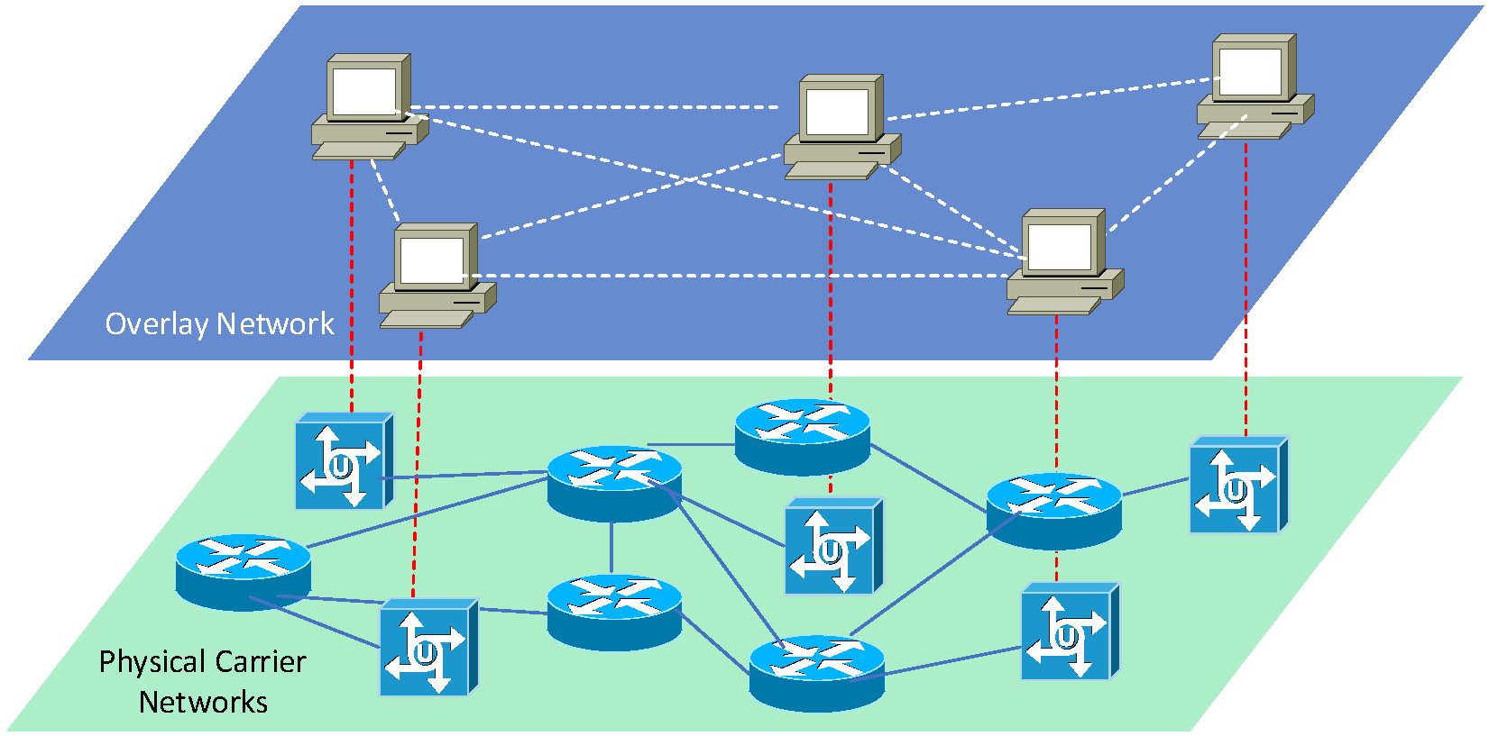
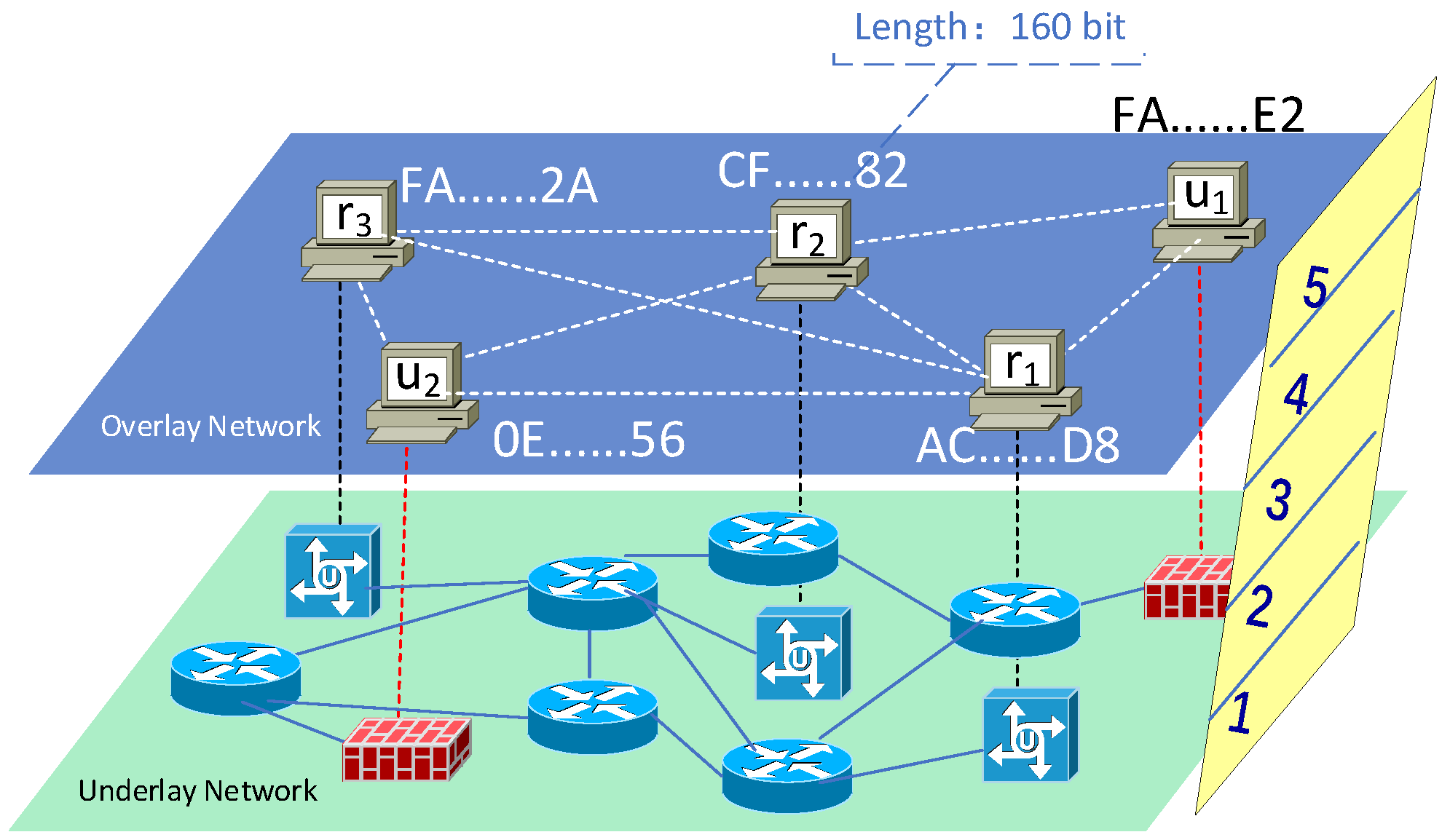
3.1. System Overview

In a traditional centralized network, any node in any network environment can directly access the centralized node and interact with data because the centralized node is always reachable, but in a decentralized network this is changed because there are no centralized nodes.
In a decentralized network, there are connectivity problems for unreachable nodes as shown in Figure 3. If simple name-to-IP conversion naming system is used only, incoming packets will be blocked due to the presence of NAT devices.
This paper combines the physical network properties with the decentralized design philosophy and gives an overview of the system organisation as shown in Figure 4. The red and black points represent reachable and unreachable nodes respectively, and their definitions will be given below.
  • Reachable node: A node directly connected in the public network environment or statically mapped from the public network environment to the internet, which can passively receive packets from other nodes through the node IP address and the specified port.
  • Unreachable node: A node that is behind one or more levels of NAT or firewall and cannot be actively accessed by other nodes through any port.
It is divided into the following parts: node identity, virtual networking, handling of unreachable nodes, routing messaging and data transmission both direct and relay connections.
Firstly, in order to enable the nodes in the decentralized network to be uniquely addressed, regardless of their geographical location and physical network. The address takes into account both the logical address of the P2P overlay network and the basis for ensuring the security of data transmission in the P2P network.
Secondly, in order to enable nodes in the network to be connected on a decentralized basis, a virtual overlay network plane is created, and special treatment is given to unreachable nodes so that unreachable nodes can be routed to each other via node addresses.
Thirdly, the data transmission mechanism of direct connections and third-node relays ensures the efficiency and availability of data transmission.
In the rest of this section we will describe the threat model and requirements in the system.

3.2. Threat Model and Assumptions

In this section we present the threats to the system at the peer-to-peer network level, transport authentication aspects and some assumptions related to them.
First of all, we make some assumptions about the system participants. Nodes in the network can join the P2P overlay network at random. They use various WAN access methods and they may be reachable nodes or unreachable nodes. Moreover, by some tests, other nodes can determine whether they are reachable nodes or unreachable nodes, and have already determined which type. Reachable and unreachable nodes together make up the entire network. They enjoy the services provided by the virtual network and also provide services to other nodes directly or indirectly, but among them there are dishonest nodes, malicious nodes, and some data eavesdroppers.
There are threats that arise at the P2P overlay network level:
(1)
Sybil Attack: This attack may occur in the virtual networking of second phase routing connection in Figure 4. This is an attack unique to decentralized networks, and if not prevented could lead to identity impersonation or even the entire network going down. As shown in Figure 5, there is no authentication authority in P2P networks, so it is costless for users to create nodes, which means that attackers can go to forge identities to join the network very easily. After that, they will try to obtain a large amount of node information in the network and make some malicious behaviors based on it, such as sending false node information, misleading the normal information transfer between nodes, faking the identity of normal nodes, not responding to network connection requests, etc.
(2)
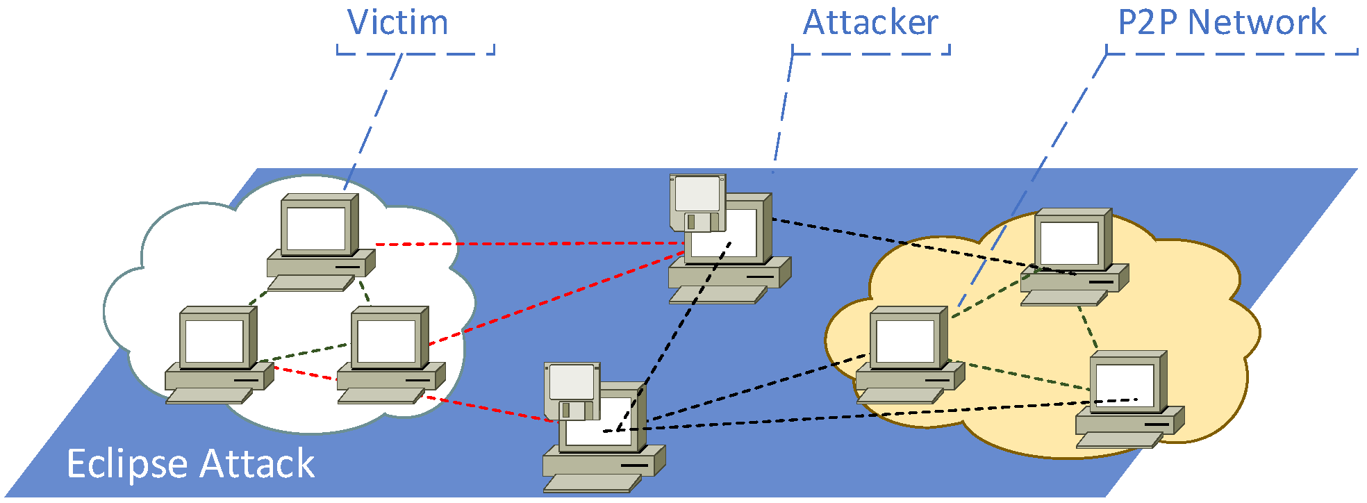
Eclipse Attack: This attack may also occur in the virtual networking of second phase routing connection in Figure 4. The eclipse attack usually has to be coupled with a Sybil attack, where the attacker adds enough fake nodes around a certain victim by appropriating the routes of nodes in the network and finding some nodes with similar addresses, thus isolating the normal nodes outside the normal P2P network, as shown in Figure 6.
(3)
DDoS Attack: This attack may occur in the routing messaging of second phase routing connection in Figure 4. In P2P networks, DDoS is different from the common centralized systems. The new DDoS attack does not require the establishment of a botnet to launch a large-scale attack, which is not only low-cost and powerful, but also ensures the secrecy of the attacker. In this way, if not prevented at the connection and authentication stages, it can have more serious consequences than centralized networks.
There are threats arising from data transmission and authentication:
(1)
Man-in-the-Middle Attack: This attack may occur in the various stages of third phase data transmission in Figure 4. In a centralized network, the authentication of the communication between two parties requires the participation of an authoritative and trusted institution, which in turn ensures the security of the authentication. In a decentralized network, there are many objects that need to communicate. On the one hand, since all nodes are peer-to-peer nodes, there is no certain authoritative centralized trusted authority. On the other hand, the overhead of authentication when communicating with a large number of nodes is too high. So authentication cannot be performed in this way, making MITM attacks more likely to occur in decentralized networks.
(2)
Replay Attacks: Replay attacks can happen during any network communication including routed messaging and data transmission in Figure 4. In decentralized networks, replay attacks on routing messages may cause an attacker to send intercepted packets repeatedly without breaking the cryptographic security, resulting in confusing routing information in P2P networks. Replay attacks on transport messages can bring about authentication problems in the network. So it is very important for the security of routed messaging and data transmission.
(3)
Data Eavesdropping Attacks: This attack may occur in the various stages of third phase data transmission in Figure 4. In the case of data encryption decrypt the data by means of MITM attack. In decentralized networks due to the more complex path of data, compared to centralized networks the possibility of attackers intercepting the packets is increased. Therefore, special care should be taken in decentralized networks to prevent such attacks.

3.3. Requirements

This section lists the requirements for implementing a P2P overlay decentralized network to achieve secure and private communication of unreachable nodes in a network that does not rely on centralized servers and does not rely on the underlying network devices to be untrusted. This includes both functional and non-functional requirements.
  • Turst: Since each node in the decentralized network can join at will and it is a non-trust environment, it is important to achieve mutual trust of nodes in the non-trust network and achieve identity authentication.
  • Privacy: Control information, routing, data, etc. transmitted between nodes or between users are not intercepted and tampered with by other nodes.
  • Security: Prevent attacks during P2P network and communication to ensure the stability and security of the whole network.
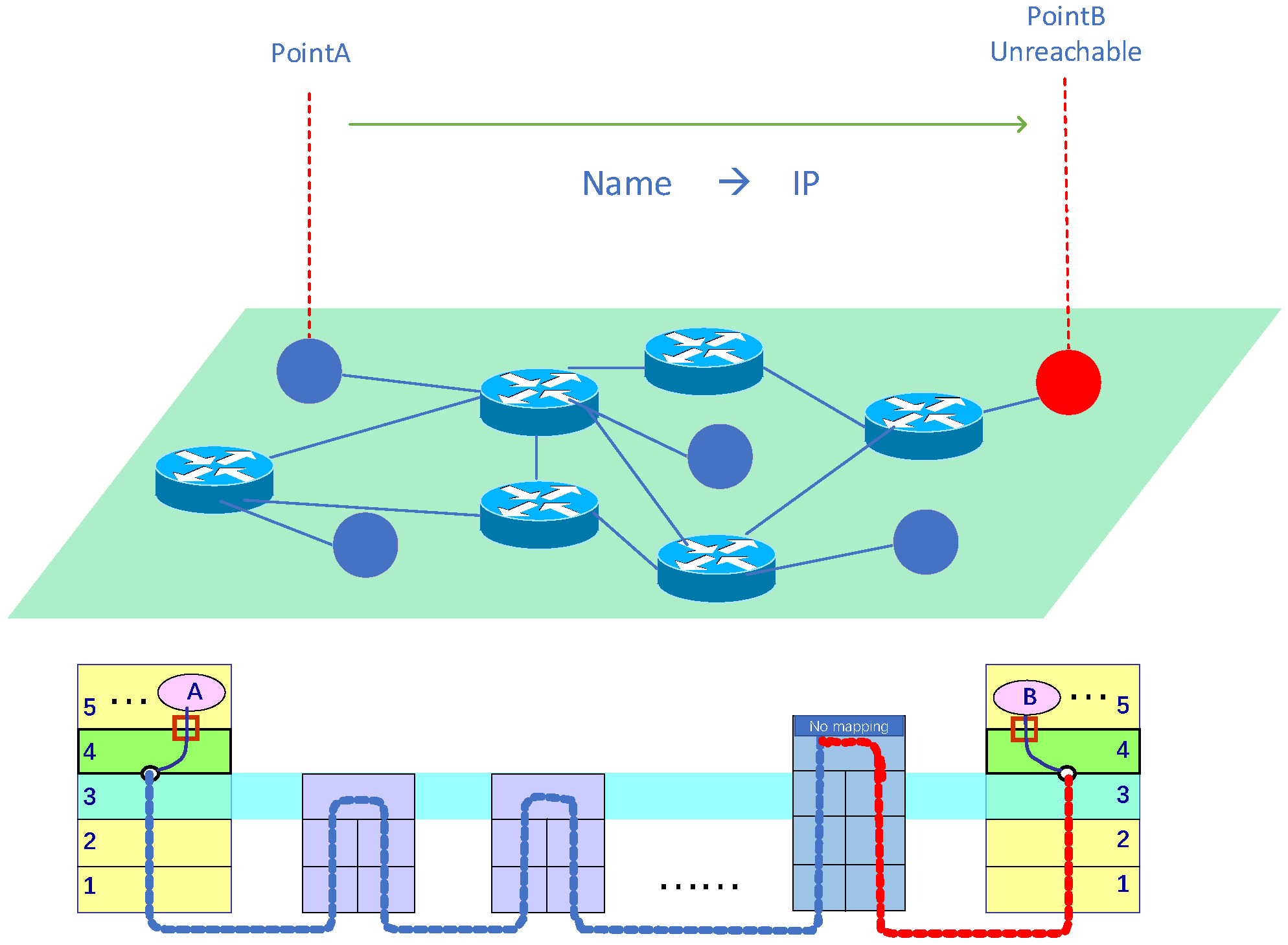
  • Search Convenience: The node is found independent of its IP address, and the conditions required to find it remain unchanged when its IP address changes, enabling IP address-independent finding of unreachable nodes.
  • Connection Efficiency: When two nodes are communicating, it is possible to quickly realize that the road has messages arriving, providing the prerequisites for establishing a connection.
  • Network Adaptability: The connection of unreachable nodes can adapt to various NAT network environments to ensure the success rate of the connection, and choose the mode of third point relay in case of unsuccessful direct connection.

4. System Design

In this section, we will focus in detail on each of the three areas node identity, virtual networking and communication channels.

4.1. Node Identity

As mentioned earlier, certain security requirements need to be met in decentralized networks, otherwise there will be significant security risks. At the same time, routing algorithms that do not rely on IP addresses need to be implemented when finding nodes. Therefore, addressing the nodes so that they can be uniquely and accurately identified is the basis for all subsequent work. This section first addresses node identity authentication and secure data transmission between nodes based on the decentralized network without a trusted institution, which provides a solid foundation for the subsequent overlay network establishment. The next section is divided into the address generation algorithm of each node that can prove its identity and the transmission and encryption authentication based on this.

4.1.1. Address Generation

In P2P overlay networks, to accommodate the needs of scenarios such as node identification and authentication, uniquely identifying each node so that the node can identify other nodes, as well as identifying any other information needed to complete authentication, the information contained directly or indirectly in the address is as follows:
  • Logical address: Logical address of the P2P overlay network, used for P2P network basic operations such as virtual networking and routing connections in DHT.
  • Identity: The unique identity used by the node for authentication, and the node performs identity authentication in both directions before transmitting information.
  • Encryption Key: The key for encrypting transmission, used to encrypt control information or routing information when transmitting.
At the same time, certain restrictions are made on the generation of addresses, requiring that the generation of this address requires a certain amount of computation. Nodes cannot be made to randomly generate addresses that are logically close to each other in order to prevent the attacks in P2P networks mentioned above.
The Node ID is calculated as defined below:
N o d e I D : = S h a 1 ( B l a k e 2 b _ 512 ( i p u b | i u k ) )
In above definition, i p u b represents the public key of the node, the node needs to generate a pair of ( i p u b , i p r i v ) , the public key is used for the generation of N o d e I D , the private key needs to be stored locally with the node. Suppose that the elliptic curve y 2 = x 3 + a x 2 + b x + c and its generator point G have been shared. We use the random number generator RNG() to generate a random number r n of length 160 bits as the private key i p r i v , and then calculate K = r n G as the public key i p u b . The public key and private key will be used for the process of authentication and encryption and decryption. i u k represents the uniform unique key in this network, which is used to break up the hash result of i p u b , so that the logical distance of N o d e I D is as large as possible and becomes irregular. b l a k e 2 b _ 512 ( . ) is a hash function that generates 512-bit message digest after execution. This digest is then used in the S h a 1 ( . ) hash algorithm to generate a final 160-bit message digest for the computed NodeID.
The difficulty D i f f n is also defined as the number of bits whose first part of the N o d e I D is continuously zero.
D i f f n : = B i n L e n ( P r e Z e r o ( N o d e I D ) )
Nodes with D i f f n less than the pre-defined the minimum D i f f n D m i n are not allowed to be routed in P2P networks, which makes the address generation of nodes difficult and requires some arithmetic power to generate a N o d e I D that can be used in the network. It can also further increase the uncertainty of address generation, and it is difficult to find the association between seed information and eligible N o d e I D information to prevent the generation of P2P network attacks in address generation.
D m i n will be determined by the average computational power of the nodes, and the N o d e I D logical distance L D i s t between the two nodes mentioned above is defined as below:
L D i s t : = N o d e I D A N o d e I D B
According to the above definition, the N o d e I D generation process is shown in Algorithm 1.
Algorithm 1: Routable N o d e I D generation algorithm in P2P overlay network
Futureinternet 14 00290 i001
The N o d e I D is generated according to the algorithm above, then compared with the known conditions D m i n until it is satisfied with the routable N o d e I D . The N o d e I D and the matching public and private keys are output for communication authentication, encryption and decryption.

4.1.2. Authentication and Encrypted Transmission

The previous section introduced the algorithm related to node identification, by which this identification and the implicit information contained can be used to achieve security and confidentiality when two nodes transmit information in an insecure channel. In order to simplify the process of node identification and encrypted communication, the following two types of network communication between nodes are classified according to the type of information transmitted between them, facilitating the selection of the appropriate type in the appropriate case.
  • Public message transmission: Transferring information that can be made public in the network between two nodes, verifying each other’s nodes’ identities, signing the authenticity of messages and preventing them from being tampered with, but not from being eavesdropped. Generally only one round of interaction takes place, so no transmission channel is established.
  • Confidential message transmission: Encrypted messages are delivered between two nodes, generally transmitting user data with large data volumes, so virtual encrypted channels are established to ensure the confidentiality of messages based on two-way identity authentication.
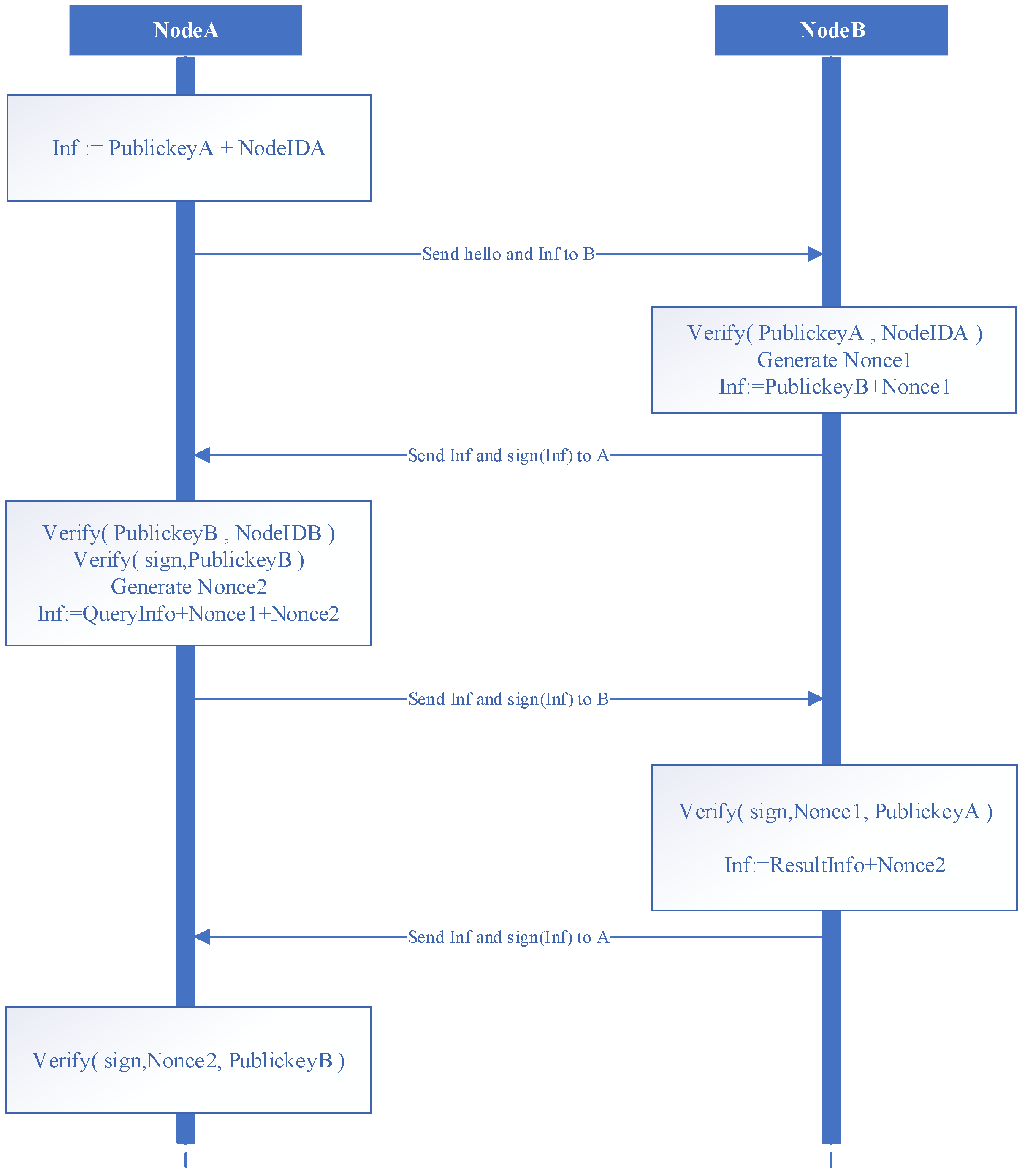
As shown in Figure 7, the interaction process of public messaging is demonstrated. The initiator is Node A and the receiver is Node B. The first interaction completes the authentication process. The second interaction completes a two-way pass of the public message. The random number mechanism prevents replay attacks and the message signature ensures that the message is tamper-proof. The detailed flow of the interaction process is as follows.
(1)
Node A first initiates a connection to Node B, sending its public key and N o d e I D .
(2)
Node B verifies that the N o d e I D and the public key sent by Node A satisfy the correspondence, as well as calculating whether D i f f n satisfies the requirements in the network. Generate the random number N o n c e 1 . Sign the public key of node B and N o n c e 1 using the private key and send the data and signature to node A.
(3)
Node A verifies that the N o d e I D and the public key sent by Node B satisfy the correspondence. Verify that the signature is correct using the public key of node B. Generate a random number N o n c e 2 . Sign N o n c e 1 , N o n c e 2 , the data to be passed using the private key, and send all data and the signature to node B.
(4)
Node B uses the public key of node A to verify that the signature of the message sent by node A is correct, compares the N o n c e 1 sent with the random number N o n c e 1 generated by node B. The data and N o n c e 2 to be sent are signed with the public key of node B, and the data and signature are sent to node A.
(5)
Node A uses the public key of node B to verify that the signature of the message sent by node B is correct, and compares whether the N o n c e 2 sent is whether the random number N o n c e 1 generated by Node A.
As shown in Figure 8, the interaction process of confidential messaging is demonstrated. The initiator is Node A and the receiver is Node B. The first interaction process completes the authentication and the generation and interaction of a new pair of public and private keys, and the second interaction process completes the key transfer for the symmetric encryption needed to establish the message channel, and then the encrypted channel is established, and Node A and Node B can communicate securely at that time. The detailed flow of the interaction process is as follows.
(1)
Node A first initiates a connection to Node B, sending its public key and N o d e I D .
(2)
Node B verifies that the N o d e I D and public key sent by node A satisfy the correspondence, as well as calculates whether D i f f n satisfies the requirements in the network. Generate a new elliptic curve private key d B , calculate H B = d B G based on the elliptic curve shared parameter base point G, sign the public key of node B and H B using the private key, and send the data with the signature result to node A.
(3)
Node A verifies that the NodeID and the public key sent by Node B satisfy the correspondence. Verify that the signature is correct using the public key of node B. Generate a new elliptic curve private key d A , compute H A = d A G . Compute symmetric key S = d A H B for DES encrypted transmission, generate I V vector at random. Sign H A and I V using the private key and send the data with the signature result to node B.
(4)
Node B uses the public key of node A to verify that the message signature from node A is correct and calculates the symmetric key S = d B H A used for DES encrypted transmission. At that time, node A and node B have the same DES encryption key S and I V vector, then use this key to encrypt the request to establish a channel command to send to node A.
(5)
After receiving the data, node A decrypts the data using S and I V . The data to be communicated can be sent to node B. The encrypted communication channel is thus established.

4.2. Virtual Networking

In this section, we will describe the detailed implementation of virtual networking. In the absence of a centralized control server and a centralized index server, the application layer of the network uses the overlay network approach, which can make any node in the network routable, including reachable and unreachable nodes, based on the logical ID of the node, independent of the IP address. The following sections describe the details related to virtual networks separately.

4.2.1. Overlay Network

This section introduces overlay network based on DHT (Distributed Hash Table) implementation. Overlay network is an application layer network, which is application layer oriented with no or little consideration of network layer and data link layer. Overlay networks allow routing messages based on logical addresses to destination hosts that are not identified by IP addresses. Without any central server, each client is responsible for a small range of routes and serves a small number of unreachable nodes, thus enabling the routing of the entire DHT network.
We define a series of nodes n 1 , n 2 , n 3 , , n n N in the overlay network plane of the application layer, as shown in Figure 9. They all have IP address-independent logical addresses generated by the same rules as defined before, with an address space of 160 bit, but their address space may become smaller due to the different definitions of D m i n , and the actual address space is ( 160 D m i n ) bits. The unique logical address generated by each node according to the algorithm is the identification of each node in the DHT network and is the basis for routing messages to be sent. We calculate the distance between two nodes using their logical distance instead of the physical distance. For example, to calculate the distance between node A and node B, we simply calculate the exclusive OR distance A B between them.
In the lower layer of the physical bearer network, we do not care about the way they access the WAN, the access location. They can use any kind of network layer, data link layer to access the network at any location, but when they access the network, they are divided into reachable nodes R = { 1 , 2 , 3 , , n } and unreachable nodes U = { 1 , 2 , 3 , , n } according to whether the node is reachable or not, R U = N . The node behind the red firewall in the Figure 9 is an unreachable node, but in the actual network access, we assume that the nodes do not know the way they access the network. They do not know the node type themselves. The node type needs to be determined with the help of nodes in the network that assist in accessing the network.
At this time, there are a series of reachable nodes r 1 , r 2 , r 3 , , r n R N and a series of unreachable nodes u 1 , u 2 , u 3 , , u n U N in the network. The type n i of nodes may change when different access methods and different locations are used to access the WAN, i.e., whether n i R or n i U can be determined only when a node is connected to the network. In different access methods, r i and u i may be transformed into each other.

4.2.2. Route Connection

In this section, we introduce the construction and connection of routes within the overlay network plane. We design how two potential types of nodes can join the virtual network and perform the corresponding functions based on Kademlia [53].
  • Bootstrap Node: In this system, first we need some bootstrap nodes so that nodes can join to the whole P2P network through them. We define a series of bootstrap nodes b 1 , b 2 , b 3 , , b n B . They are all reachable nodes, B R . When a node wants to join the P2P network, it first connects to any bootstrap node b i and then integrates into the whole P2P network according to the algorithm. A total of n bootstrap nodes serve as a backup for each other and also share the pressure of network connection. The bootstrap nodes need to expose the N o d e I D , IP address and port number < N o d e I D , I P , P o r t > after booting so that nodes can connect to them with this information. The triad can be hard-coded in the system, or it can be dynamically updated and obtained using DNS system. Additionally, load-balanced DNS also allows for a balanced distribution of traffic across bootstrap nodes.
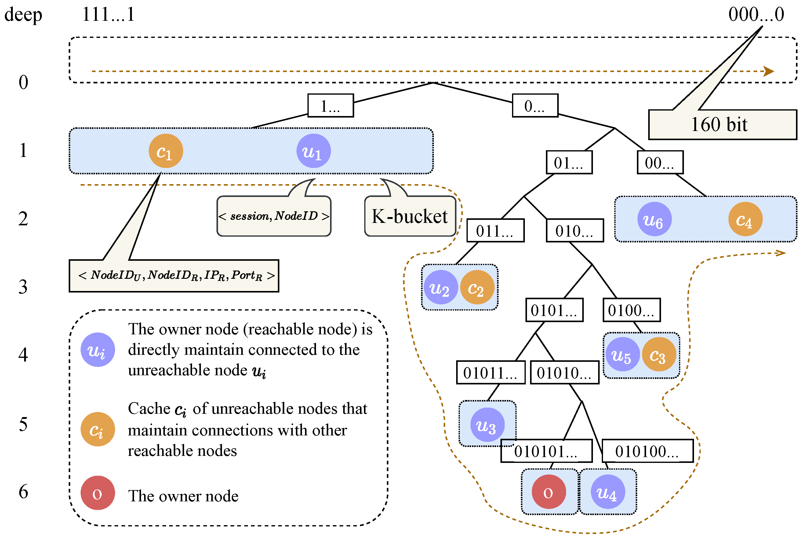
  • K-bucket: Each reachable node U has two k-buckets, which are stored in a binary tree. One of the k-buckets is used to store the logical address information of other reachable nodes, which can be used to find the nearest reachable node quickly. The definition of k-buckets and binary trees, and the update algorithm are the same as the standard Kademlia algorithm. The function a d d k b u c k e t R ( N o d e I D , I P , P o r t ) is defined to store another reachable node at the reachable node.
The other k-bucket of the reachable node is used to store two kinds of data. The first one is the connection session and N o d e I D < s e s s i o n , N o d e I D > of the unreachable nodes to which this node directly maintains connections. The second one store the information of unreachable nodes that maintain connection with other reachable nodes cached by this node, the information of unreachable nodes themselves, and the information of reachable nodes that unreachable nodes maintain connection < N o d e I D U , N o d e I D R , I P R , P o r t R > . Define the function a d d k b u c k e t U ( S e s s i o n , N o d e I D ) to add the unreachable node information in the second type of k-bucket, and the function a d d k b u c k e t U b u f f ( N o d e I D U , N o d e I D R , I P R , P o r t R ) to add the cache of unreachable nodes.
This k-bucket can be represented as a binary tree, as shown in Figure 10. The dashed rectangle at the top represents the result of the middle-order traversal of the binary tree, with the nodes with all binary bits of 1 on the left, decreasing from left to right, and the nodes with all binary bits of 1 on the far right. The following is a dynamic binary tree, where each leaf node is a k-bucket that splits and merges according to certain rules. From the root node down, the left branch of each subtree represents bit 1 and the right branch represents bit 0. Each branch down the binary tree node has a common prefix of logical address.
Initially, only the most specific own node is stored in this structure. When the cache of other unreachable nodes or nodes is added, it is inserted into the corresponding k-bucket according to the N o d e I D of the node. When the number of nodes in a particular k-bucket reaches the maximum number of nodes K specified by the system, the k-bucket is split before adding more nodes. The next bit of the current subtree is selected for splitting, bit 1 for the left subtree and bit 0 for the right subtree. The nodes in the current k-bucket are selected to enter the k-bucket in the left subtree or the right subtree according to this bit. When the k-bucket splits to the maximum level specified by the system, no more splits will be made. However, if the k-buckets are all unreachable nodes in which this node directly remains connected, they will not be restricted by this condition. When there are two types of nodes in a k-bucket and the maximum number of split levels has been reached, the node cache with the lowest access frequency will be removed when the directly connected unreachable nodes or node caches are added again. When the number of nodes in a particular k-bucket decreases, the merge operation of the k-bucket will be executed if the merge condition is satisfied.
  • Node joining: As mentioned earlier, the node joins the overlay network by first connecting to the bootstrap node. Then it becomes part of the network by joining to the network through the node. The joining algorithm of nodes is shown in Algorithm 2.
Algorithm 2: Nodes (reachable nodes R , unreachable nodes U ) join algorithm
Futureinternet 14 00290 i002
When node n i randomly connects to the last bootstrap node b i , the bootstrap node first makes a judgment on the node type of n i , which can be known as n i R or n i U . If the node type is the reachable node c i , then n i needs to join the routing network and participate in the construction of the routing table of the whole network. Firstly, it inserts its own node into its own k-bucket, as shown in Figure 10 for node o. Then execute F i n d N o d e operation of the Kademlia algorithm to update its own k-bucket according to the received information. Then these nodes are queried sequentially from near to far. In this way, while constructing its own routing table, it also inserts its information into the routing table of the neighboring nodes. If the node type is unreachable node r i , then n i does not need to be added to the routing network and does not participate in the construction of the routing table for the whole network. First, the F i n d N o d e operation is executed to extract the N nodes with the smallest logical distance from its own based on the received information. Then connections are established with each of these N nodes to make these nodes aware of their own information and add them to the k-bucket. Subsequently, these connections need to be continuously maintained.
Node joining is a dynamic process where nodes need to do some operations cyclically after joining to the network to ensure their own availability and that of the whole network. The unreachable and reachable nodes have to do the following operations respectively.
  • Unreachable node: After joining the network, the unreachable node needs to keep alive the long connection with N nodes, in addition to executing lines 12–20 of Algorithm 2 cyclically to ensure that it is always connected to the N nodes closest to its address. When a closer node is found, the long connection to the more distant node is disconnected while contact is made with the closer node.
  • Reachable node: After the reachable nodes join the network, they need to respond to the query operations of other nodes with the connection operations of unreachable nodes. In this process, the two k-buckets are split and merged in a timely manner according to the k-bucket update method described in the previous section. The long connection with the unreachable node is periodically tested for normalness, and if it is adjudged to be a deactivated node, this node is removed from the k-bucket.

4.2.3. Peer Discovery for Unreachable Node

In this section we introduce peer discovery within the overlay network plane, in particular discovery and routing messaging between unreachable nodes. If there are only reachable nodes in the network, the F i n d N o d e operation can be used to achieve peer discovery. However, there are reachable nodes R and unreachable nodes U in the network, and both r i and u i have the same address format, so it is impossible to make a distinction in the address. So we want to implement a generalized algorithm that, given an address of c i , without knowing the node n i is r i or n i is u i , the routing connection of this node can be obtained according to Algorithms 3 and 4.
When a node in the network wants to find a node of unknown type based on NodeID, assuming that it does not store this node and this node’s cache in its own k-bucket, it first finds the nearest α nodes to this point in its own k-bucket. Then send F i n d P e e r s ( ) requests to each of these nodes based on their < N o d e I D , I P , P o r t > and ask these nodes to query the target node for information. When the result is received, it updates its own k-bucket based on the result. If the N o d e I D to be looked up is still not in the result after the request is sent for each node, then the process is looped. In the current state, find the nearest α nodes to this point in its own k-bucket again and send a request query to each of them.
When the target node is found, it is determined whether the target node is a reachable node, if it is then it is directly connected based on the < N o d e I D , I P , P o r t > of the node and then the transmission channel is established. If it is an unreachable node, then it is necessary to first establish a connection with the node directly connected to this node, and then use the method in the next section to establish a data transmission channel with the unreachable node. Then, the nearest α node in the k-bucket is added to this node to the cache using the a d d k b u c k e t U b u f f ( . ) function.
Algorithm 3: Nodes (reachable nodes R , unreachable nodes U ) lookup (discovery) algorithm
Futureinternet 14 00290 i003
Algorithm 4: FindPeers() procedure in reachable nodes
Futureinternet 14 00290 i004
The F i n d P e e r s ( ) function in the reachable nodes is implemented in Algorithm 4. When a reachable node receives a request from another node, it first queries its first k-bucket and returns the information of the target node directly if there is a target node. If not, then query its own second k-bucket to see if there is a target node, and if there is then return the data of its own node directly. If there is a cache of the target node, the data of the node directly connected to the target node is returned. If there is no check in both k-buckets, the nearest α node from the first k-bucket to the target node is queried and returned.

4.3. Communication Channels

This section describes the final step of the unreachable node communication scheme, the establishment of the communication channel. After the routing connection is completed, the nodes can interact with each other with simple data, but cannot transmit data. The establishment of the data channel, combined with node identity-based authentication and data encryption, allows for secure and fast data transmission between the two nodes. Depending on how the two nodes access the network, there are two ways of establishing the connection: direct connection and third-node relay. The former does not take up additional network resources but some access methods cannot be used and the latter is widely available but takes up third-node network resources. The direct connection mode is used in order not to consume too many network resources and allows two nodes to communicate directly after the communication channel has been established. However, this mode is not available for some network access methods, where a direct transmission channel cannot be established to an unreachable node, and then a third-node relay mode is required. The following two sections describe the connection details for both direct connection establishment and third-node relay modes respectively.

4.3.1. Connection Directly
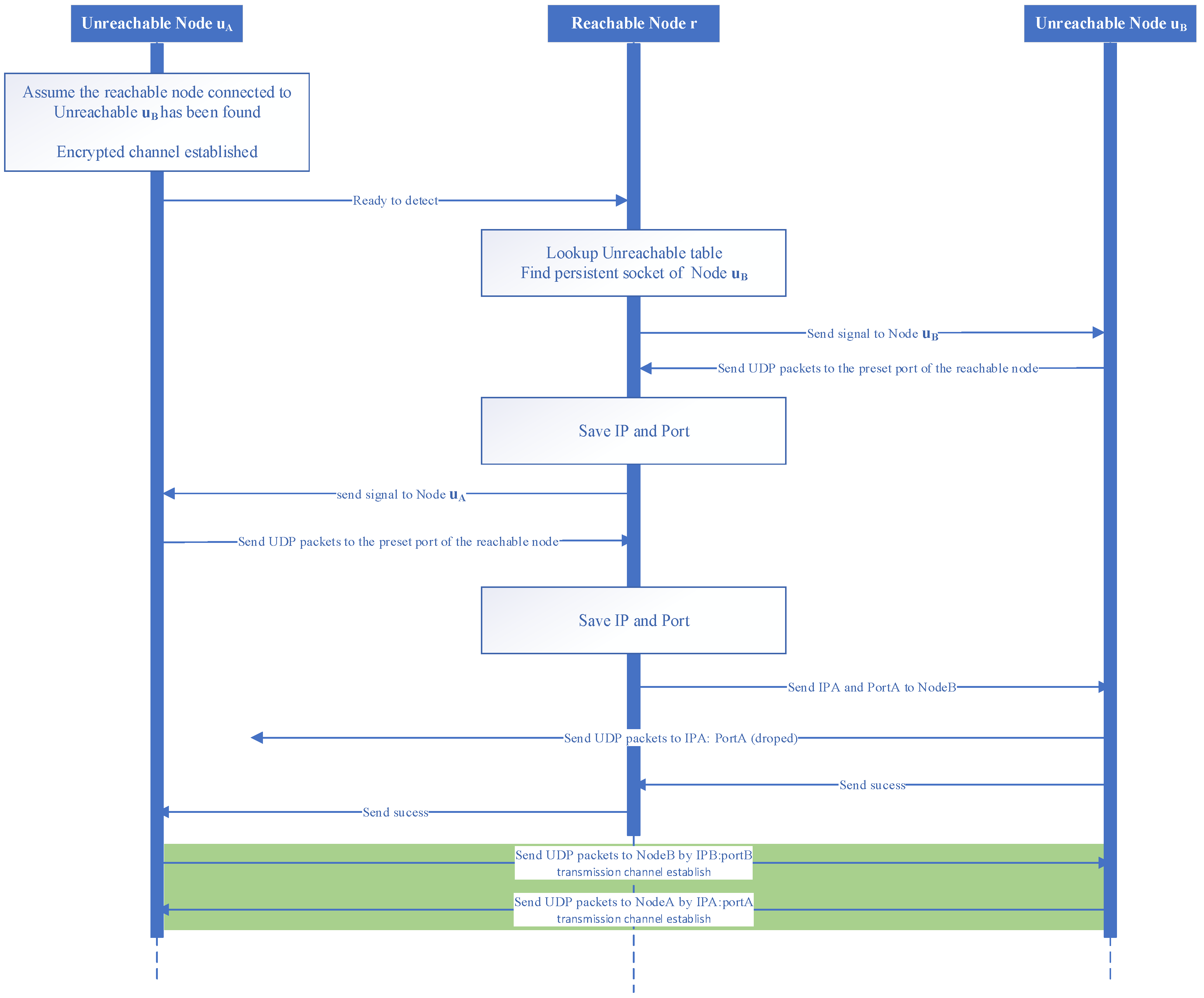
This section will describe the direct connection mode for unreachable nodes. As shown in Figure 11, in the previous steps, node u A has been contacted by node u B through a route lookup in the overlay network, but needs to transfer messages through the reachable node to which it is connected and can only perform simple message transfer. The yellow arrows in the upper plane indicate data transmission in the virtual plane and the yellow arrows in the lower plane indicates data transmission between routers in the physical bearer network. The next step is to make the two unreachable nodes connect directly with the help of this reachable node, as shown in Figure 12. As the unreachable node does not have an IP address and port for active access to the public network, all messages are forwarded by the reachable node before the connection is obtained. These messages are also authenticated and encrypted by the method previously described, thus ensuring security in transmission.
Specifically, when nodes u A and u B establish a direct connection, they obtain their mapped IP address and port number in the public network by actively sending packets out. If the other node opens this port for it in its previous NAT or firewall device, then it can use the IP address and port number mapped in the public network to transmit packets directly to and from the unreachable node, thus completing the establishment of the communication channel. The detailed steps for establishing a communication channel between unreachable nodes u A and u B are as follows.
(1)
First, assume that node u A has already determined that node u B is unreachable by the method described previously, and has found a reachable node r that maintains a long connection with node u B , and has already established an encrypted transmission channel. When the u A node and the u B node have the intention to establish a communication channel, an initialisation message to help establish the connection is sent to the reachable node r.
(2)
The reachable node r receives the message and finds the long connection session of node u B in its own table of unreachable nodes, and sends to node u B a message about the wish of node u A to connect and an already open UDP port.
(3)
The u B node receives the message and sends a UDP packet to the open port of the reachable node r and informs the reachable node r via a long connection.
(4)
The reachable node r receives the UDP packet and records the IP address and port number of the source of the packet. This is the IP address and port number that the u B node maps to the public network, and then sends this information to the u A node along with an open UDP port of the reachable node r.
(5)
After receiving the message, node u A sends a UDP packet to the open port of reachable node r and informs reachable node r via a long connection.
(6)
Reachable node r receives a UDP packet and records the IP address and port number of the source of the packet. This is the IP address and port number that node u A maps to the public network and then sends this information to node u B .
(7)
The u B node receives it and sends a UDP packet to the IP address and port number that the u A node injects into the public network. Obviously this packet will not be received by u A because the NAT device or firewall prior to node u A does not have this address mapped. However, the NAT device or firewall prior to node u B has created a mapping for this IP address to the port. After sending the UDP packet a message is sent to the reachable node that the transmission has been completed.
(8)
Reachable node r receives this message and forwards it to node u A .
(9)
After receiving this message, node u A sends a UDP packet to the IP address and port number of node u B mapped to the public network.
(10)
At this point the u B node can accept the packet as it has already established a mapping in the previous NAT device or firewall. Next, a UDP packet is sent to the IP address and port number mapped to the public network by node u A . At this point the direct connection data channel has been successfully established.
It should be noted that the unreachable node u A and the reachable node, the unreachable node u B and the reachable node and, finally, the unreachable nodes u A and u B are authenticated and encrypted using the previous method based on N o d e I D , which ensures transmission security and is not described in detail in Figure 12 and in the detailed steps.

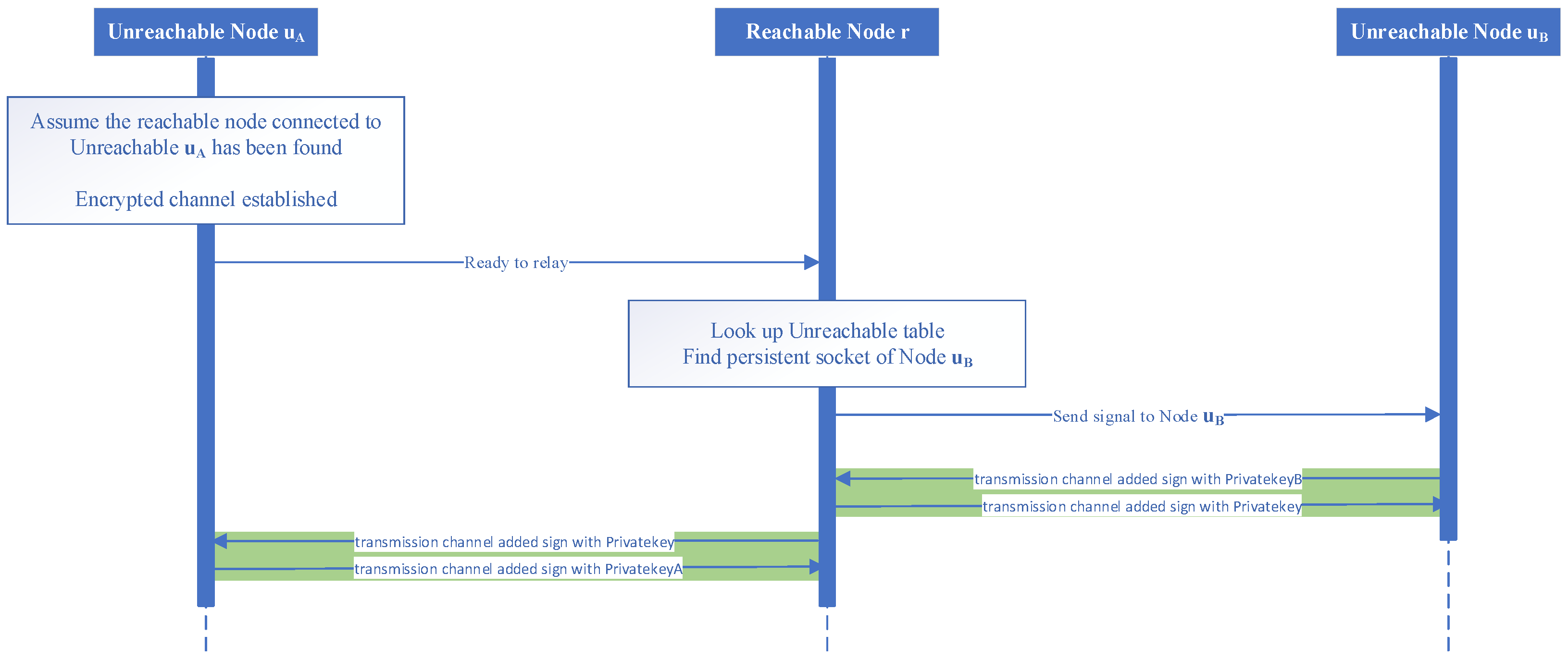
4.3.2. Connection by Third-Node Relay

This section will describe the direct connection mode for two unreachable nodes. The direct connection method may be unsuccessful due to the NAT type of the network device behind the unreachable node accessing the network. In case of unsuccessful use of the scheme described in this section, as shown in Figure 13, is the same as the direct connection scheme, where in the previous steps node u A has already been contacted by node u B through a route lookup in the overlay network. Later it is necessary to establish the forwarding transmission channel of the reachable node r with the assistance of the reachable node r, as shown in Figure 14. A transmission channel is established between unreachable node u A and reachable node r, unreachable node u B and reachable node r, respectively to forward data. Unreachable nodes u A and u B at both ends are authenticated and encrypted using the methods shown in the previous section. Reachable node r only forwards data and does not participate in authentication and encryption. The detailed steps for establishing a communication channel between the unreachable nodes u A and u B are as follows.
(1)
First, assume that node u A has already determined that node u B is unreachable by the method described previously, and has found a reachable node r that maintains a long connection with node u B , and has already established an encrypted transmission channel. When the u A node and the u B node have the intention to establish a communication channel, an initialisation message to help establish the connection is sent to the reachable node r.
(2)
Reachable node r receives the message and finds the long connection session of node u B in its own table of unreachable nodes and sends a message to node u B about the wish of node u A to connect.
(3)
Once received by the u B node, a transmission channel to the reachable node is established using public message transmission. At this time messages can be viewed by a third party, but are tamper-proof.
(4)
After the establishment of the transmission channel is complete, the reachable node r establishes a transmission channel with the u A node.
(5)
After the establishment is complete, the authentication between unreachable nodes u A and u B is started.
Up to this point, any node in the overlay network can be discovered and a secure transmission channel can be established and data can be transmitted. We use a decentralized scheme to implement data communication between unreachable nodes in the system that does not rely on trusted third parties and achieves the establishment of data communication channels between unreachable nodes while retaining the advantages of a decentralized system.

5. Evaluation

In this section, we will study and analyze the unreachable node communication scheme in this paper. First we evaluate the address generation algorithm to verify that node identification plays a fundamental role in the overall network to ensure the security and privacy of the network system. Then, we evaluate the overlay network based on a simulated scheme to verify the usability of the decentralized scheme in this paper, which is divided into the evaluation of the virtual networking, i.e., routing scheme and the evaluation of the connection channel establishment.

5.1. Address Generation Evaluation

In this section, we will evaluate the address generation algorithm, divided into the performance of randomly generated addresses and the scattering of randomly gene-rated addresses.
First, we evaluate the performance of randomly generated addresses. We assume that D m i n is 16, i.e., only the number of consecutive bits preceding the generated address that are 0 is greater than or equal to 16 can be used as a node that can be used for normal communication in the network. We implemented the algorithm using Java and completed the experimental framework. To reduce experimental error and for statistical purposes, our experiments were divided into five groups, each of which generated addresses that were not limited by D m i n 1000 times, and then we counted the metrics in each group of address generation experiments.
We conducted our experiments on a computer with an Inter i5-3470 CPU, 4GB of RAM and Ubuntu 18.04 as the operating system. We counted the total time consumed by each set of experiments, the average time consumed per address generated, and the number of valid addresses and the number of addresses with BinLen of 8 or more under the above assumptions. The results of the experiments are shown in Table 1.
Among the five groups of experiments, we observed that the shortest total time spent was 589 s in group 3, where the average time taken to generate each address was 589 ms. The longest total time spent was 660 s in group 5, where the average time taken to generate each address was 660 ms. The highest number of valid addresses generated among the five groups was in group 5, with five valid addresses. The lowest number was group 3, with no valid addresses. The highest number of addresses with BinLen of 8 or more generated in the five experimental groups was group 5, with 62 addresses. The least was group 3 with 43 addresses.
Next, we evaluate the dispersion of randomly generated addresses, i.e., the logical distance dispersion of node addresses. We assume that D m i n is 0, i.e., all generated node addresses can be used as nodes in the network that can be used for normal communication. We generated 1000 addresses using the same method as above and then calculated the maximum, minimum, average and variance of these 1000 addresses, as shown in Table 2.

5.2. P2P Network Simulation Method

In order to verify the usability of the communication scheme for unreachable nodes in decentralized networks proposed in this paper, we will simulate reachable and unreachable nodes, and the process of their sending and receiving packets, using methods that are as close to the real environment as possible. Although there are some P2P simulation methods available, most of them are based on a single program that simulates the algorithms running in an overlay network and cannot distinguish between nodes based on their network properties, and cannot simulate the real packet transmission process and the interruptions such as network delays that are generated in between. It also does not simulate the IP address and other infrastructure used for network transmission in a real environment, and therefore cannot simulate the process of establishing connections to unreachable nodes behind NAT or firewall. For this reason, we have used a real network environment, real IP addresses and other infrastructure and packet sending and receiving processes to test the availability and performance of the unreachable node communication scheme in the network.
Specifically, we used n ECS under the same proprietary network as the experimental virtual machines in the simulation, and they were on the same subnet and could communicate with each other through private addresses. The specifications of each ECS are 64 vCPU, Core 3.5 GHz, 128 GB RAM, 40 GB SSD, 32 Gbps of intranet bandwidth, 12 million PPS of intranet packets sent and received, and Ubuntu 18.04 operating system.
The scheme is organised as shown in Figure 15. n ECS ( e c s 1 , e c s 2 , , e c s n ) are connected to the virtual switch vSwitch via virtual ports v E t h 0 , v E t h 1 , , v E t h n , which contains a DHCP server that provides the ECS that access the network with IP address for the network segment 172.19.80.0/20. In each ECS we simulate simultaneous running nodes by means of independent threads, each bound to a socket, which also communicate with each other via the 172.19.80.0/20 network segment, but the packets are forwarded directly by the local switch instead of passing through the vSwitch. To simulate the unreachable node u i more realistically, the socket of the unreachable node will not accept external active connections, but only return packets from connections it has initiated. In addition, there is a console, ECS control center, which maintains a connection to the master process in e c s 1 , e c s 2 , , e c s n via vSwitch, thus establishing a connection to each node for functional control of the node and data collection.
It has been verified that in this configuration where the number of ECS running nodes does not exceed 1000, CPU time slice rotation does not significantly affect the algorithms run by the nodes, while the latency in transmitting packets is basically indistinguishable between each node in the same ECS and those in different ECS, and they can be considered to be on equal status. During the simulation run, in order to reduce the time required for each node to reach a relatively stable state prior to the experiment, the control center helps each node to reach a stable state as soon as possible by updating the k-bucket through the calculation of global addresses, but it will not be involved in this work when the experiment starts after this time.

5.3. Network Evaluation

In this section we evaluate the network connectivity aspects, including virtual routing and the creation of communication channels. We have implemented the routing of reachable nodes r i , unreachable nodes u i and the establishment of transmission channels for unreachable nodes in JAVA based on the standard Kademlia algorithm based on the method described above. To facilitate the management of the nodes, we create a thread for each node in the main program, which does not communicate with the main process except to guide behaviour and statistics, but transmits packets through a virtual switch in the same way as the real network.

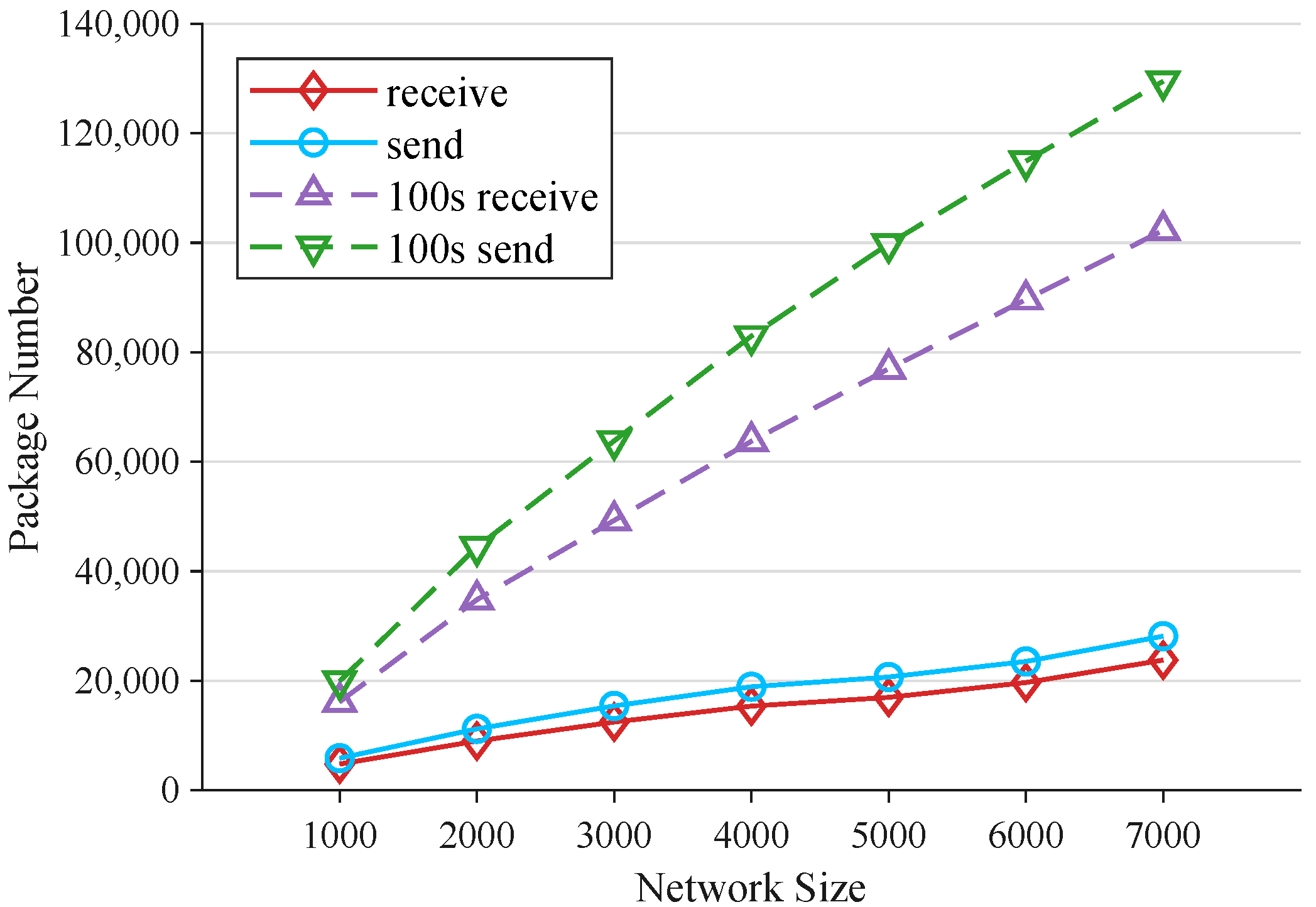
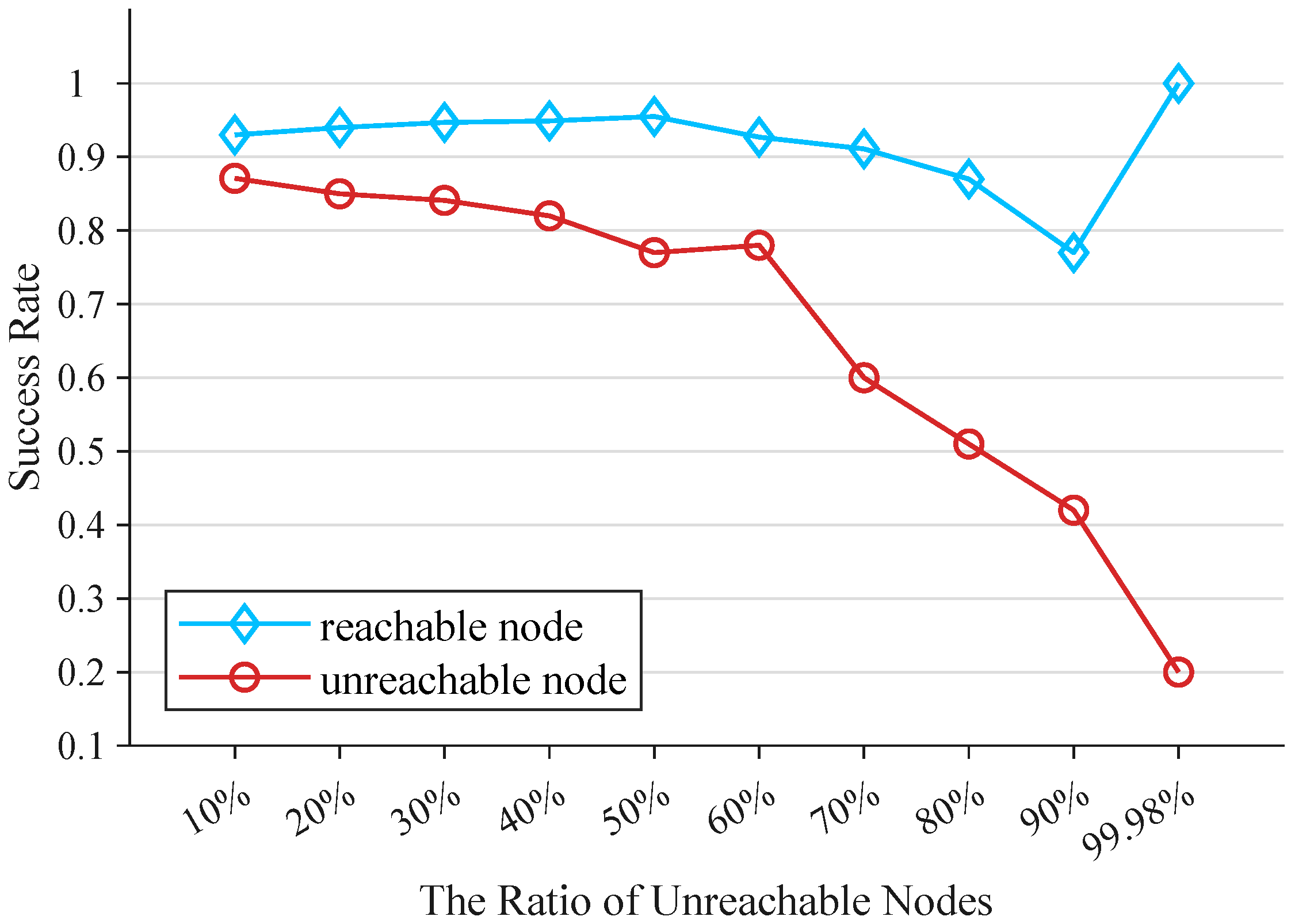
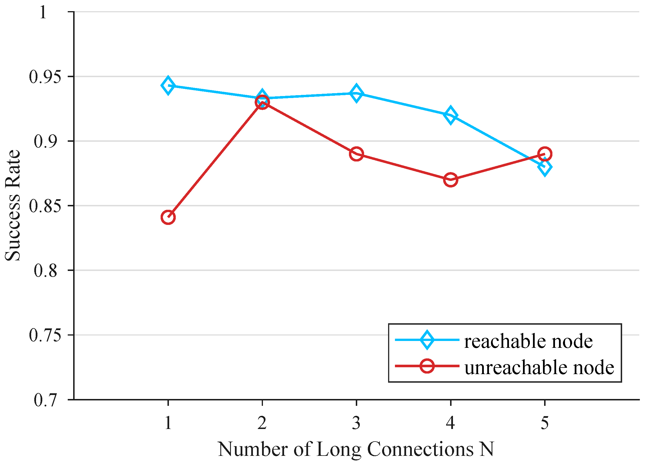
5.3.1. Virtual Network Evaluation

In this section we evaluate the metrics of reachable nodes that have joined the physical bearer network and unreachable nodes joining the overlay network plane and the success rate of lookups. We use the previous address generation algorithm to generate 7000 addresses, which are randomly assigned to each node via the control node, without distinguishing between reachable and unreachable nodes, and record the addresses with the node’s IP address and port number for backup.
First, we evaluate the joining of nodes to the overlay virtual plane. To avoid single point failure and single point bottleneck of the bootstrap nodes, we randomly selected five nodes as bootstrap nodes, hard-coded the bootstrap nodes into the control center, and the nodes randomly selected a bootstrap node when joining the overlay network. We used a total of 7000 nodes for our experiments and randomly selected 30% of them, 2100 nodes, as unreachable nodes u i and the remaining 4900 nodes as reachable nodes, with the bootstrap nodes included in the reachable nodes r i . The reachable and unreachable nodes are randomly distributed among all nodes. The parameter N for the unreachable nodes to access the network is taken as 1. Two sets of experiments were conducted. In the first set of experiments, when the bootstrap node is created and the rest of the nodes join the overlay network through the bootstrap node in turn, we obtain the average value of packets sent and received by the nodes in the network when 1000, 2000, 3000,..., 7000 nodes join the network. In the second set of experiments, the rest of the nodes join the overlay network through the bootstrap nodes in turn. We pause the joining of the rest of the nodes when 1000, 2000, 3000,..., 7000 nodes join the network, then wait for 100 s and obtain the average value of the packets sent and received by the nodes in the network. The experimental results are shown in the four curves in Figure 16.
The lower two curves show the number of packets sent and received by nodes joining without waiting time, while the upper two curves show the number of packets sent and received after 100 s of waiting time, both of which show an increasing trend. The difference between the top two curves is larger than the bottom two curves and tends to increase as the number of nodes increases, while the difference between the bottom two curves remains more or less the same. Overall, the slope of the two curves decreases slowly as the number of nodes increases and does not exceed 1 at the maximum slope, indicating that the average consumption of network resources by nodes becomes smaller as the network size increases. As the size of the network increases, the tendency to increase the average time complexity of building the network and the interactive refresh work after building decreases, which is a beneficial effect for us to build larger networks.
Next, we verified the success rate of finding reachable and unreachable nodes. As in the previous experiment, we used 30% of unreachable nodes and set N to 1. We constructed overlay networks of 1000, 2000, 3000,..., 7000 nodes and brought the nodes to a stable state of the DHT. Then, we select no less than 10 reachable nodes, and no less than five reachable nodes and no less than five unreachable nodes for each reachable node for different network size cases, and count the number of successes in each group as a proportion of the total number of successes, as shown in Figure 17.
In the figure we can see that the success rate is high when the network is small, with both unreachable and reachable nodes reaching around 96%. As the size of the network increases the success rate of reachable nodes decreases slightly, and the unreachable nodes start to decrease more at 4000 nodes, but then levels off at larger network sizes. As the size of the network increases, the success rate of the reachable and unreachable node lookups may be reduced by more network packets being sent and the node k-bucket refreshing. The significant decrease in the success rate of unreachable nodes at 4000 nodes may be caused by the interference generated when querying unreachable node addresses to each reachable node due to network congestion. As the ratio of unreachable nodes increases, the success rate of reachable nodes slightly increases probably because fewer reachable nodes are involved in DHT construction, while unreachable nodes do not have a significant impact on reachable nodes. Starting from 60% of unreachable nodes, the success rate of reachable nodes decreases probably because a large number of unreachable nodes occupy network resources and have an impact on the refreshing of DHT of reachable nodes, which can be confirmed by the rapid decrease of the success rate of unreachable nodes after 60%.
We then explore the effect of the proportion of unreachable nodes on the network. First, we randomly generate 5000 node addresses, without distinguishing between reachable and unreachable nodes. Then, with a constant total number of nodes and a constant number of long connections of unreachable nodes of 1, we investigate the effect of the ratio of unreachable nodes at 10%, 20%, 30%,..., 90%, and converging to 100% of the proportion of unreachable nodes in the overlay network were experimented with separately. In each group of experiments, when the nodes reach the steady state of the DHT, no less than ten reachable nodes are selected, and no less than five reachable nodes and no less than five unreachable nodes are selected for each reachable node respectively, and the success rate of the lookup are shown in Figure 18.
In the figure we can see that the reachable nodes show a stable state when the proportion of unreachable nodes is low, with a tendency to increase as the proportion increases, and the success rate starts to drop when the proportion is high. The success rate of unreachable nodes fluctuates when the proportion is below 60%, fluctuates around 85%, and decreases rapidly when the proportion is above 60%, until finally the success rate is only 20%.
Finally, we explore the effect of the size of the number N of unreachable nodes maintaining long connections on the success rate of the lookup. First, we randomly generate 5000 node addresses, without distinguishing between reachable and unreachable nodes. Then, we randomly select 30% of these 1500 nodes as unreachable nodes and the remaining 3500 nodes as reachable nodes, with the bootstrap nodes included in the reachable nodes. We take N as 1, 2, 3, 4, 5 to construct the DHT stable overlay network respectively. For each group of experiments, as before, no less than 10 reachable nodes are selected, and no less than five reachable nodes and no less than five unreachable nodes are selected for each reachable node respectively, and the success rate of the lookup is shown in Figure 19.
In the figure we can see that the success rate of finding reachable nodes decreases slightly as N increases. When N is 2, the success rate of unreachable nodes rises significantly compared to when N is 1, and fluctuates when N is greater than 2. As the number of long connections N increases, redundancy is created in finding unreachable nodes in the network, avoiding the failure of finding them due to the network or some nodes, so the success rate increases significantly at N of 2 compared to 1. However, that the success rate of unreachable node lookup decreases slightly for N of 3 to 5 may be due to the fact that the multiple long connections maintained in this network construction mode burden the network as a whole and the nodes are hindered in updating their own resources.

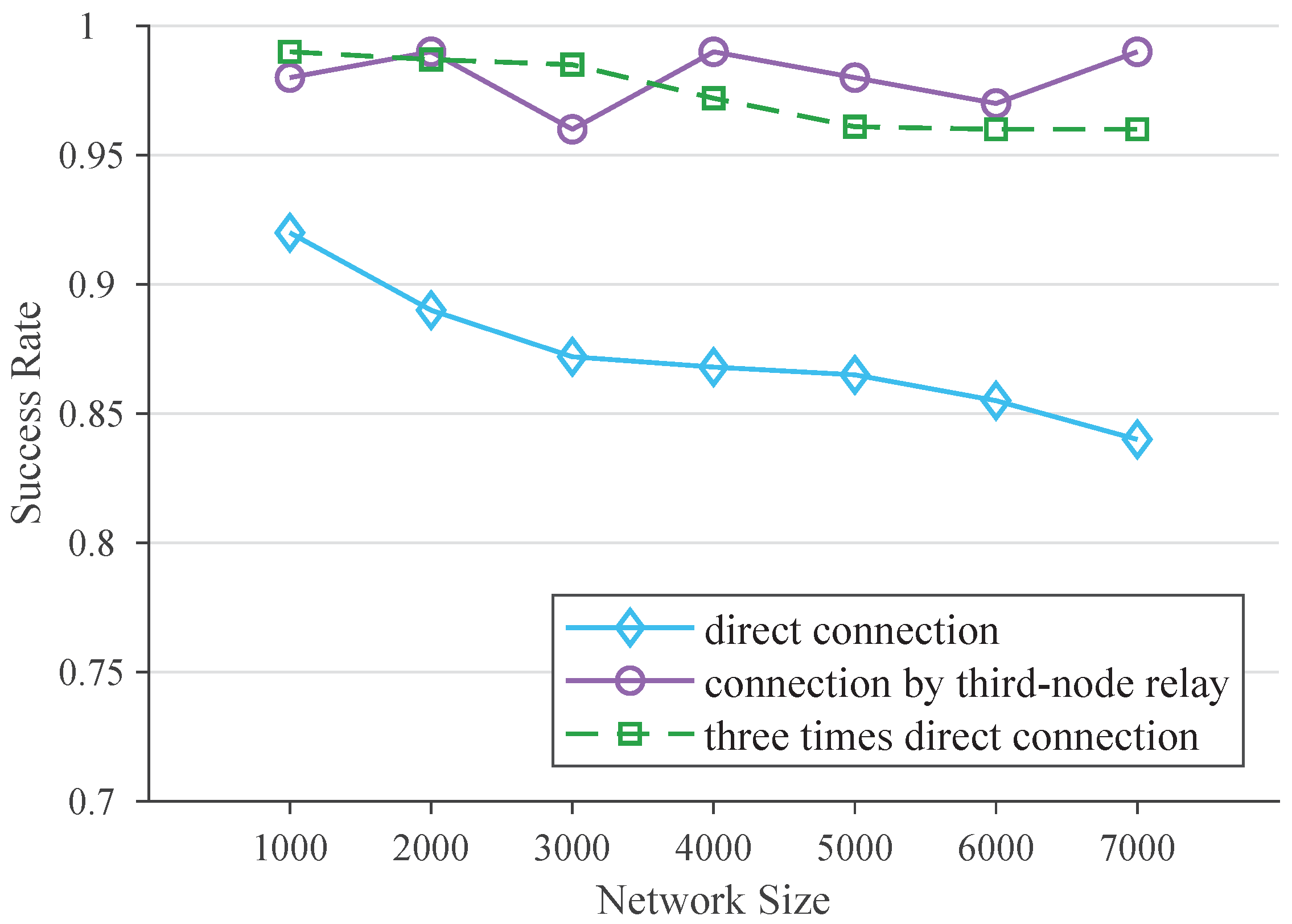
5.3.2. Communication Channels Establish Evaluation

In this section, we evaluate two communication channel establishment schemes. As in the previous section, we randomly select five nodes as the bootstrap nodes and hard-code the bootstrap nodes into the control nodes. A total of 7000 nodes are used for the experiments and 30% of them, 2100 nodes, are randomly selected as unreachable nodes and the remaining 4900 nodes are used as reachable nodes, and the bootstrap nodes are included in the reachable nodes. The reachable nodes and unreachable nodes are randomly distributed among all nodes. The parameter N for unreachable nodes to access the network is taken as 1. We construct DHT stable overlay networks of 1000, 2000, 3000,..., 7000 nodes respectively. Then, we verify the success rate of the two schemes in different network size cases by selecting not less than 10 unreachable nodes and not less than 5 unreachable nodes randomly selected for each reachable node respectively. The transmission channels were established between them using direct connection, relay connection, and direct connection three times, and the success rates of the two schemes in establishing communication channels based on the success of DHT lookup were counted, as shown in Figure 20.
In the figure we can see that the relaying scheme is not greatly affected by the network size and the success rate is always close to 100%. The success rate of the direct connection scheme decreases slightly as the network size increases, but the three times attempts of the direct connection scheme significantly increase the success rate of communication channel establishment.
The relay solution is less affected by the network condition because it does not need to establish a direct transmission channel for network packets, and the success rate is fluctuating without a decreasing trend. The success rate of the direct connection scheme gradually decreases with the increase of network size because it needs to establish mapping relationships on NAT devices or firewalls, and the increase of network size will reduce the success rate of this link. However, direct connection three times will increase the success rate of establishing mapping relationship, so it makes the success rate of the scheme increase significantly. Overall, the success rates of the direct connect three times and the third point relay scheme are basically the same, but the direct connect three times decreases slightly when the network size increases, which is also within the available range. Therefore, in use, it is still necessary to give priority to the direct connection scheme, and if the connection is not successful because of the network access method, the relay scheme is used, which will minimize the overall network resource consumption.

6. Discussion

This paper introduces a communication scheme for unreachable nodes in decentralized networks. This scheme does not rely on third-party platforms such as trusted institutions, is not limited by IP addresses, and can establish a secure transmission channel between any two nodes. In the following, we will discuss each part of the implementation of the communication scheme, discuss its role for the whole system, and finally we analyze and discuss the communication scheme as the whole.
First, we will discuss address generation. We define the address generation algorithm and the legitimate address requirements in overlay networks. On the one hand, the implicit information can be used to achieve authentication and transmission encryption with the participation of a centralized trustworthy agency, which prevents attacks such as data theft. On the other hand, the address containing the unique key i u k generated under the calculation of two hash algorithms with the regulation of D m i n ensures the randomness of address generation with the generation process consuming computational resources, which prevents the attacks in P2P networks.
Specifically, the address pre-generation step uses two different hash functions to do two consecutive hash operations on the randomly generated public key with i u k , which ensures the randomness of the generated addresses. If an attacker wants to pre-generate two node addresses with very similar addresses, assume that he has already selected two i p u b with close logical distance by elliptic curve, but when the two hash functions run as specified by the algorithm are completed, the results will be redistributed in the address space because of the characteristics of the hash functions and the logical distance will not exist, thus preventing the eclipse attack. The D m i n setting makes address generation require some computation, i.e., continuous computation to obtain the available addresses in the network, which makes it impossible for a particular node to assume a large number of identities in a short period of time, thus preventing sybil attacks. The nodes in the network include the need to verify that the node’s identity and address match before any interaction, which prevents an attacker without a legitimate identity from assuming multiple identities to initiate connections to other normal nodes, thus guarding against DDoS attacks. In addition, the implicit mapping relationship between the node address and i p u b makes it possible for both public and confidential message transfers to mutually verify the correctness of the claimed i p u b , which fundamentally eliminates i p u b substitution and prevents man-in-the-middle attacks. The signature of the public message transmission after adding a random number to the message and the signature of the confidential message transmission when a symmetric key is passed prevent replay attacks and data tampering. In this way, the security settings in the address generation algorithm achieve malicious node prevention and data security assurance in P2P networks without relying on centralized trusted institutions.
Then, we discuss the virtual network, which is the “skeleton” of the whole solution, connecting all nodes that contain reachable and unreachable nodes. Instead of a trusted centralized organization, such as a centralized cloud platform, we use overlay network technology to store the indexes of all the nodes in the network, including both reachable and unreachable nodes, decentralized in each reachable node via DHT. In the experiments, a thread-based node simulation close to the real environment is used to simulate the data interaction between nodes through real packet delivery. For network construction, network lookup is evaluated. Network construction indirectly estimates the time complexity of the construction algorithm by the trend of the average packets at different network sizes, which shows a decreasing trend as the network size increases. The above shows that the network construction as well as the success rate of lookup meets the basic needs of decentralized network scenarios for applications such as IoT, which can be used in scenarios such as decentralized smart homes. In addition, in our other two sets of experiments on the impact of the ratio of unreachable nodes to the number of long connections N on the network, we suggest that the ratio of unreachable nodes in the network should not exceed 60%. When the ratio of unreachable nodes is high, the increase in long connections maintained by each reachable node and the increase in query packets in the network lead to a decrease in the efficiency of unreachable node lookup. The number of long connections N is chosen according to the size of the network, and as the size of the network increases, a larger number of N can bring out the optimal lookup performance of the entire network for unreachable nodes.
Next, we discuss the establishment of the communication channel, which is the last step before two nodes have to communicate, and after successfully establishing the communication channel, they can communicate without restrictions. Our scheme provides two methods, direct connection between two nodes and a third-node relay, both of which require an assisted connection to a reachable node that maintains a long connection with an unreachable node. In our experiments, we verified that the success rate of direct connection is essentially the same as that of third-node relay connection three times, and direct connection has higher complexity in establishing the connection channel than third-node relay. However, after the communication channel is established, the third-node relay scheme needs this node to always forward network traffic, which consumes additional network resources on the one hand and tends to form a network bottleneck on the other. Therefore, when a large amount of data need to be transmitted, the direct connection scheme is preferred, and only when the direct connection scheme fails to establish the communication channel, the relay scheme is selected as a backup.
Finally, we discuss the communication scheme of this paper in its entirety. The address generation algorithm with the use of the implicit information contained in this address replaces the CA authority in the traditional scheme and allows authentication and communication encryption without the help of a trusted authority. The establishment of virtual network and communication channel replaces the centralized cloud platform in the traditional scheme, which can realize virtual routing and data transmission without relying on IP address without the help of a trusted centralized institution. The whole system no longer relies on the centralized platform and trusted institutions, and the user owns the device democracy and has autonomous control over the device, which brings help for privacy issues and centralized single point of failure due to centralized institutions, such as IoT smart home using centralized cloud platform with MQTT [54], CoAP [55] and other protocols. For the decentralized solution, compared to the decentralized naming system, our solution solves the finding and communication of unreachable nodes with unreachable IP addresses and the guarantee of transmission security without relying on additional third-party platforms. We compare their main 8 metrics as shown in Table 3.
In Table 4, we compare in detail three schemes related to our work about decentralized solutions. In contrast to the Keizer et al. [51], our scheme uses a structured P2P network as a decentralized networking scheme containing unreachable nodes in the overlay network, and achieves logical Node ID addressing-based routing between unreachable nodes through the DHT structured scheme, which improves the node lookup efficiency, eliminates the flooding bottleneck, and reduces the resource consumption when looking up nodes. At the same time, we establish peer-to-peer data transmission channels in two schemes, direct connection and relay. We choose the direct connection scheme when the network allows, saving the data flow resources in the network. In contrast to Kamel et al. [52], our scheme does not need to rely on a third party centralized institution to organize the cloud nodes, so it has good for autonomy and device democracy. The establishment of the data channel in this paper is improved in terms of real-time data transmission compared to the end-to-end communication using messaging in the scheme, while a large amount of data can be transmitted continuously when the data channel is established. Compared with the decentralized PCP and decentralized SDN [34,45] schemes, our scheme can establish a peer-to-peer data transmission channel without relying on ISP’s equipment support, which is more applicable. At the same time, compared with the blockchain as the medium of data interaction, the structured P2P network used in this paper as the organization scheme of the overlay network makes the data transmission in the overlay plane specific and does not require network-wide broadcast to find a particular node. Compared with the above schemes, the proposed scheme in this paper does not rely on the support of third-party trusted institutions for data security assurance. The proposed algorithm for generating node addresses in the overlay network either shows or implicitly contains the logical address in the DHT, the identification for node identification and the encryption seed information in the address information. Based on these, user authentication and transmission encryption can be completed, so it does not rely on third-party CA trusted institutions and is a completely decentralized scheme.

7. Conclusions

This paper introduces the problem of unreachable nodes communicating with each other arising from the transition from the centralized to the decentralized network phase. The proposed solution mentioned in the related work for the centralized network is incompatible with the decentralized network due to the need for additional trusted third-party servers. We propose a communication scheme for unreachable nodes in decentralized networks to solve this problem. The solution does not rely on third-party trusted institutions such as CA institutes and centralized cloud platforms, and does not rely on the IP addresses of nodes when finding nodes, and can choose to establish secure direct or relay transmission channels between any two nodes depending on the network conditions. We experimentally verify the feasibility of address generation, virtual networking, and communication channel establishment of the solution. Compared with existing solutions, our solution enables users to have device democracy, improves on data privacy and security, and also avoids single point of failure. Moreover, the solution solves the routing problem of unreachable nodes using structured DHT, and can establish direct or relayed transmission channels to unreachable nodes, improving in communication methods and efficiency.

Author Contributions

Conceptualization, G.L.; Methodology, G.L.; Supervision, C.W. and H.W.; Validation, C.W. and H.W.; Writing—original draft, G.L.; Writing—review & editing, C.W. and H.W. All authors have read and agreed to the published version of the manuscript.

Funding

This research received no external funding.

Data Availability Statement

All data were presented in main text.

Conflicts of Interest

The authors declare no conflict of interest.

References

  1. Leiner, B.M.; Cerf, V.G.; Clark, D.D.; Kahn, R.E.; Kleinrock, L.; Lynch, D.C.; Postel, J.; Roberts, L.G.; Wolff, S. A brief history of the Internet. ACM SIGCOMM Comput. Commun. Rev. 2009, 39, 22–31. [Google Scholar] [CrossRef]
  2. Sharma, N.; Shamkuwar, M.; Singh, I. The history, present and future with IoT. In Internet of Things and Big Data Analytics for Smart Generation; Springer: Berlin/Heidelberg, Germany, 2019; pp. 27–51. [Google Scholar]
  3. Gumrukcu, E.; Arsalan, A.; Muriithi, G.; Joglekar, C.; Aboulebdeh, A.; Zehir, M.A.; Papari, B.; Monti, A. Impact of Cyber-attacks on EV Charging Coordination: The Case of Single Point of Failure. In Proceedings of the 2022 4th Global Power, Energy and Communication Conference (GPECOM), Buenos Aires, Argentina, 26–28 February 2020; IEEE: New York, NY, USA, 2022; pp. 506–511. [Google Scholar]
  4. Stark, E.; Sleevi, R.; Muminovic, R.; O’Brien, D.; Messeri, E.; Felt, A.P.; McMillion, B.; Tabriz, P. Does certificate transparency break the web? Measuring adoption and error rate. In Proceedings of the 2019 IEEE Symposium on Security and Privacy (SP), San Francisco, CA, USA, 19–23 May 2019; IEEE: New York, NY, USA, 2019; pp. 211–226. [Google Scholar]
  5. Li, B.; Lin, J.; Li, F.; Wang, Q.; Li, Q.; Jing, J.; Wang, C. Certificate transparency in the wild: Exploring the reliability of monitors. In Proceedings of the 2019 ACM SIGSAC Conference on Computer and Communications Security, London, UK, 11–15 November 2019; pp. 2505–2520. [Google Scholar]
  6. Chen, F.; Duan, H.; Zheng, X.; Jiang, J.; Chen, J. Path Leaks of HTTPS Side-Channel by Cookie Injection. In Proceedings of the International Workshop on Constructive Side-Channel Analysis and Secure Design, Singapore, 23–24 April 2018; Springer: Berlin/Heidelberg, Germany, 2018; pp. 189–203. [Google Scholar]
  7. Oukemeni, S.; Rifà-Pous, H.; Puig, J.M.M. Privacy analysis on microblogging online social networks: A survey. ACM Comput. Surv. (CSUR) 2019, 52, 1–36. [Google Scholar] [CrossRef] [Green Version]
  8. Mare, S.; Girvin, L.; Roesner, F.; Kohno, T. Consumer smart homes: Where we are and where we need to go. In Proceedings of the 20th International Workshop on Mobile Computing Systems and Applications, Santa Cruz, CA, USA, 27–28 February 2019; pp. 117–122. [Google Scholar]
  9. Pouwelse, J.; Garbacki, P.; Epema, D.; Sips, H. The bittorrent p2p file-sharing system: Measurements and analysis. In International Workshop on Peer-to-Peer Systems; Springer: Berlin/Heidelberg, Germany, 2005; pp. 205–216. [Google Scholar]
  10. Honigsberg, P.J. The evolution and revolution of Napster. USFL Rev. 2001, 36, 473. [Google Scholar]
  11. Nakamoto, S. Bitcoin: A peer-to-peer electronic cash system. Decentralized Bus. Rev. 2008, 21260. Available online: https://bitcoin.org/bitcoin.pdf (accessed on 1 September 2022).
  12. Wood, G. Ethereum: A secure decentralised generalised transaction ledger. Ethereum Proj. Yellow Pap. 2014, 151, 1–32. [Google Scholar]
  13. Dai, W.; Dai, C.; Choo, K.K.R.; Cui, C.; Zou, D.; Jin, H. SDTE: A secure blockchain-based data trading ecosystem. IEEE Trans. Inf. Forensics Secur. 2019, 15, 725–737. [Google Scholar] [CrossRef]
  14. Kalbantner, J.; Markantonakis, K.; Hurley-Smith, D.; Akram, R.N.; Semal, B. P2PEdge: A Decentralised, Scalable P2P Architecture for Energy Trading in Real-Time. Energies 2021, 14, 606. [Google Scholar] [CrossRef]
  15. Zheng, S.; Pan, L.; Hu, D.; Li, M.; Fan, Y. A blockchain-based trading platform for big data. In Proceedings of the IEEE INFOCOM 2020—IEEE Conference on Computer Communications Workshops (INFOCOM WKSHPS), Toronto, ON, Canada, 6–9 July 2020; IEEE: New York, NY, USA, 2020; pp. 991–996. [Google Scholar]
  16. Ma, X.; Ma, J.; Li, H.; Jiang, Q.; Gao, S. ARMOR: A trust-based privacy-preserving framework for decentralized friend recommendation in online social networks. Future Gener. Comput. Syst. 2018, 79, 82–94. [Google Scholar] [CrossRef]
  17. Jiang, L.; Zhang, X. BCOSN: A blockchain-based decentralized online social network. IEEE Trans. Comput. Soc. Syst. 2019, 6, 1454–1466. [Google Scholar] [CrossRef]
  18. Bhattacharjya, A.; Zhong, X.; Wang, J.; Li, X. On mapping of address and port using translation. Int. J. Inf. Comput. Secur. 2019, 11, 214–232. [Google Scholar] [CrossRef]
  19. Ibhaze, A.E.; Okoyeigbo, O.; Samson, U.A.; Obba, P.; Okakwu, I.K. Performance evaluation of IPv6 and IPv4 for future technologies. In Proceedings of the Future of Information and Communication Conference, San Francisco, CA, USA, 5–6 March 2020; Springer: Berlin/Heidelberg, Germany, 2020; pp. 15–22. [Google Scholar]
  20. Zander, S.; Wang, X. Are we there yet? IPv6 in Australia and China. ACM Trans. Internet Technol. (TOIT) 2018, 18, 1–20. [Google Scholar] [CrossRef]
  21. Hamarsheh, A.; Abdalaziz, Y.; Nashwan, S. Recent impediments in deploying IPv6. Adv. Sci. Technol. Eng. Syst. 2021, 6, 336–341. [Google Scholar] [CrossRef]
  22. Egevang, K.; Francis, P. The IP Network Address Translator (NAT); RFC 1631; Internet Engineering Task Force (IETF): Fremont, CA, USA, 1994. [Google Scholar]
  23. Benet, J. Ipfs-content addressed, versioned, p2p file system. arXiv 2014, arXiv:1407.3561. [Google Scholar]
  24. Henningsen, S.; Florian, M.; Rust, S.; Scheuermann, B. Mapping the interplanetary filesystem. In Proceedings of the 2020 IFIP Networking Conference (Networking), Paris, France, 22–25 June 2020; pp. 289–297. [Google Scholar]
  25. Wang, L.; Pustogarov, I. Towards better understanding of bitcoin unreachable peers. arXiv 2017, arXiv:1709.06837. [Google Scholar]
  26. Baset, S.A.; Schulzrinne, H. An analysis of the skype peer-to-peer internet telephony protocol. arXiv 2004, arXiv:cs/0412017. [Google Scholar]
  27. Saldamli, G.; Upadhyay, C.; Jadhav, D.; Shrishrimal, R.; Patil, B.; Tawalbeh, L. Improved gossip protocol for blockchain applications. Clust. Comput. 2022, 25, 1915–1926. [Google Scholar] [CrossRef]
  28. Silvano, W.F.; Marcelino, R. Iota Tangle: A cryptocurrency to communicate Internet-of-Things data. Future Gener. Comput. Syst. 2020, 112, 307–319. [Google Scholar] [CrossRef]
  29. Guidi, B.; Michienzi, A.; Ricci, L. A libP2P Implementation of the Bitcoin Block Exchange Protocol. In Proceedings of the 2nd International Workshop on Distributed Infrastructure for Common Good, Virtual Event Canada, 6–10 December 2021; pp. 1–4. [Google Scholar]
  30. Petit-Huguenin, M.; Salgueiro, G.; Rosenberg, J.; Wing, D.; Mahy, R.; Matthews, P. Session Traversal Utilities for NAT (STUN); RFC 8489; IETF: Wilmington, DE, USA, 2020. [Google Scholar]
  31. Reddy, T.; Johnston, A.; Matthews, P.; Rosenberg, J. Traversal Using Relays around NAT (TURN): Relay Extensions to Session Traversal Utilities for NAT (STUN); RFC 8656; IETF: Wilmington, DE, USA, 2020. [Google Scholar]
  32. Wing, D.; Cheshire, S.; Boucadair, M.; Penno, R.; Selkirk, P. Port Control Protocol (PCP); Technical Report; IETF: Wilmington, DE, USA, 2013. [Google Scholar]
  33. Boucadair, M.; Penno, R.; Wing, D. Universal Plug and Play (Upnp) Internet Gateway Device-Port Control Protocol Interworking Function (IGD-PCP IWF); RFC 6970; Internet Engineering Task Force (IETF): Fremont, CA, USA, 2013. [Google Scholar]
  34. Kfoury, E.F.; Gomez, J.; Crichigno, J.; Bou-Harb, E.; Khoury, D. Decentralized distribution of PCP mappings over blockchain for end-to-end secure direct communications. IEEE Access 2019, 7, 110159–110173. [Google Scholar] [CrossRef]
  35. Patsonakis, C.; Samari, K.; Kiayiasy, A.; Roussopoulos, M. On the practicality of a smart contract PKI. In Proceedings of the 2019 IEEE International Conference on Decentralized Applications and Infrastructures (DAPPCON), Newark, CA, USA, 4–9 April 2019; pp. 109–118. [Google Scholar]
  36. Ali, M.; Nelson, J.; Shea, R.; Freedman, M.J. Blockstack: A global naming and storage system secured by blockchains. In Proceedings of the 2016 USENIX Annual Technical Conference (USENIX ATC 16), Denver, CO, USA, 22–24 June 2016; pp. 181–194. [Google Scholar]
  37. Cheshire, S.; Krochmal, M. Nat Port Mapping Protocol (Nat-Pmp); Technical Report; IETF: Wilmington, DE, USA, 2013. [Google Scholar]
  38. Xia, W.; Wen, Y.; Foh, C.H.; Niyato, D.; Xie, H. A survey on software-defined networking. IEEE Commun. Surv. Tutor. 2014, 17, 27–51. [Google Scholar] [CrossRef]
  39. Wang, H.C.; Chen, C.; Lu, S.H. An sdn-based nat traversal mechanism for end-to-end iot networking. In Proceedings of the 2019 20th Asia-Pacific Network Operations and Management Symposium (APNOMS), Matsue, Japan, 18–20 September 2019; IEEE: New York, NY, USA, 2019; pp. 1–4. [Google Scholar]
  40. Subratie, K.; Figueiredo, R. Towards island networks: SDN-enabled virtual private networks with peer-to-peer overlay links for edge computing. In Proceedings of the International Conference on Internet and Distributed Computing Systems, Tokyo, Japan, 11–13 October 2018; Springer: Berlin/Heidelberg, Germany, 2018; pp. 122–133. [Google Scholar]
  41. Kavalionak, H.; Payberah, A.H.; Montresor, A.; Dowling, J. Natcloud: Cloud-assisted nat-traversal service. In Proceedings of the 31st Annual ACM Symposium on Applied Computing, Pisa, Italy, 4–8 April 2016; pp. 508–513. [Google Scholar]
  42. Garcia, B.; Gortazar, F.; Lopez-Fernandez, L.; Gallego, M.; Paris, M. WebRTC testing: Challenges and practical solutions. IEEE Commun. Stand. Mag. 2017, 1, 36–42. [Google Scholar] [CrossRef]
  43. Novo, O. Making constrained things reachable: A secure IP-agnostic NAT traversal approach for IoT. ACM Trans. Internet Technol. (TOIT) 2018, 19, 1–21. [Google Scholar] [CrossRef]
  44. Saka, R.; Uehara, M. Web API-based NAT traversal in managed network blocks. In Proceedings of the Conference on Complex, Intelligent, and Software Intensive Systems, Matsue, Japan, 4–6 July 2018; Springer: Berlin/Heidelberg, Germany, 2018; pp. 660–669. [Google Scholar]
  45. Kim, G.; Kim, J.; Lee, S. An SDN based fully distributed NAT traversal scheme for IoT global connectivity. In Proceedings of the 2015 International Conference on Information and Communication Technology Convergence (ICTC), Jeju Island, Korea, 28–30 October 2015; IEEE: New York, NY, USA, 2015; pp. 807–809. [Google Scholar]
  46. Hansen, H.V.; Goebel, V.; Plagemann, T. DevCom: Device communities for user-friendly and trustworthy communication, sharing, and collaboration. Comput. Commun. 2016, 85, 14–27. [Google Scholar] [CrossRef]
  47. Ford, B. UIA: A Global Connectivity Architecture for Mobile Personal Devices. Ph.D. Thesis, Massachusetts Institute of Technology, Cambridge, MA, USA, 2008. [Google Scholar]
  48. Ding, D.; Conti, M.; Figueiredo, R. SAND: Social-aware, network-failure resilient, and decentralized microblogging system. Future Gener. Comput. Syst. 2019, 93, 637–650. [Google Scholar] [CrossRef]
  49. Aslanoglou, C.; Konstantopoulos, M.; Chondros, N.; Roussopoulos, M. Take Back your Friends with DCS: A Decentralized Connectivity Service for private social communication apps. In Proceedings of the 2020 IEEE International Conference on Decentralized Applications and Infrastructures (DAPPS), Oxford, UK, 3–6 August 2020; IEEE: New York, NY, USA, 2020; pp. 133–138. [Google Scholar]
  50. Kfoury, E.; Khoury, D. Securing natted iot devices using ethereum blockchain and distributed turn servers. In Proceedings of the 2018 10th International Conference on Advanced Infocomm Technology (ICAIT), Stockholm, Sweden, 12–15 August 2018; IEEE: New York, NY, USA, 2018; pp. 115–121. [Google Scholar]
  51. Keizer, N.V.; Ascigil, O.; Psaras, I.; Pavlou, G. Rewarding relays for decentralised nat traversal using smart contracts. In Proceedings of the Twenty-First International Symposium on Theory, Algorithmic Foundations, and Protocol Design for Mobile Networks and Mobile Computing, Virtual, 11–14 October 2020; pp. 309–314. [Google Scholar]
  52. Kamel, M.; Ligeti, P.; Nagy, A.; Reich, C. Distributed Address Table (DAT): A decentralized model for end-to-end communication in IoT. Peer-Netw. Appl. 2022, 15, 178–193. [Google Scholar] [CrossRef]
  53. Maymounkov, P.; Mazieres, D. Kademlia: A peer-to-peer information system based on the xor metric. In Proceedings of the International Workshop on Peer-to-Peer Systems, Cambridge, MA, USA, 7–8 March 2002; Springer: Berlin/Heidelberg, Germany, 2002; pp. 53–65. [Google Scholar]
  54. Soni, D.; Makwana, A. A survey on mqtt: A protocol of internet of things (iot). In Proceedings of the International Conference on Telecommunication, Power Analysis and Computing Techniques (ICTPACT-2017), Chennai, India, 6–8 April 2017; Volume 20, pp. 173–177. [Google Scholar]
  55. Tariq, M.A.; Khan, M.; Raza Khan, M.T.; Kim, D. Enhancements and challenges in coap—A survey. Sensors 2020, 20, 6391. [Google Scholar] [CrossRef]
  56. Rais, R.N.B.; Abdelmoula, M.; Turletti, T.; Obraczka, K. Naming for heterogeneous networks prone to episodic connectivity. In Proceedings of the 2011 IEEE Wireless Communications and Networking Conference, Cancun, Mexico, 28–31 March 2011; IEEE: New York, NY, USA, 2011; pp. 1091–1096. [Google Scholar]
Figure 1. Two modes of network communication. (a) Center model. (b) Peer-to-peer model.
Futureinternet 14 00290 g001
Figure 2. Overlay networks on top of physical carrier networks.
Futureinternet 14 00290 g002
Figure 3. Unreachable nodes are discarded directly from the packet.
Futureinternet 14 00290 g003
Figure 4. The overview of the system organisation.
Futureinternet 14 00290 g004
Figure 5. Sybil attack diagram.
Futureinternet 14 00290 g005
Figure 6. Eclipse attack diagram.
Futureinternet 14 00290 g006
Figure 7. The workflow of public message transmission.
Futureinternet 14 00290 g007
Figure 8. The workflow of confidential message transmission.
Futureinternet 14 00290 g008
Figure 9. The overlay network is an application layer network with a series of reachable nodes r 1 , r 2 , r 3 and unreachable nodes u 1 , u 2 in the plane, and they have the same format of 160 bit logical addresses; The lower underlay network represents layers 1 to 4 of the TCP/IP stack, with nodes accessing the network in different ways and at different locations.
Futureinternet 14 00290 g009
Figure 10. The k-bucket of reachable nodes represented using a binary tree. There are three types of nodes in the k-bucket, which are represented by three colors. For clarity of presentation, not all of the 160 bit address space is shown.
Futureinternet 14 00290 g010
Figure 11. Direct connection packet flow diagram for unreachable nodes u A and u B in the overlay and underlay planes.
Futureinternet 14 00290 g011
Figure 12. Flowchart of the direct data transmission channel of the unreachable nodes u A and u B .
Futureinternet 14 00290 g012
Figure 13. Packet flow diagram of unreachable nodes u A and u B in the overlay and underlay planes establishing connections via reachable node r relays.
Futureinternet 14 00290 g013
Figure 14. Flow chart of unreachable nodes u A and u B establishing data transmission channels via reachable node r relays.
Futureinternet 14 00290 g014
Figure 15. ECS experimental architecture.
Futureinternet 14 00290 g015
Figure 16. Average packet numbers for building overlay networks at different network size.
Futureinternet 14 00290 g016
Figure 17. Lookup success rate of reachable and unreachable nodes at different network size.
Futureinternet 14 00290 g017
Figure 18. Lookup success rate of reachable and unreachable nodes with different ratio of unreachable nodes.
Futureinternet 14 00290 g018
Figure 19. Lookup success rate of reachable and unreachable nodes with different number of long connections N.
Futureinternet 14 00290 g019
Figure 20. Success rates of two methods of establishing communication channels at different network size.
Futureinternet 14 00290 g020
Table 1. Node addresses generate five sets of experimental results.
GroupNumberTimeAverage Time of per Time8 bit ‘0’16 bit ‘0’
11000605 s0.605 s471
21000653 s0.653 s533
31000589 s0.589 s430
41000621 s0.621 s552
51000660 s0.660 s625
Table 2. Statistical information for 1000 addresses.
ItemNumerical Value (HEX)
Maximum0xffffb1931c879140b7561882a8953cb7abef14f3
Minimum0x502a121f6e286d8eda6c1a0f411bdf07e5d3
Average0x801e79cb28bc725f94b84c200bb522dc4ef9efe0
Variance0x1.54f215601abd8E+80
Table 3. A comparison of three types of solutions.
NAT Traversal
Capability
DecentralizedCentralized
Authority
Central
Bottlenecks
Additional
Deployments
Encryption and Authentication
Security Dependencies
User
Autonomy
Transmission Security
Centric solutions [54,55]YesNoYesYesYesCA InstitutionsNoCentralized institutional customization
Decentralized naming systems [36,46,47,56]NoYesNo——————Yes——
Decentralized solutions in this paperYesYesNoNoNoCryptographic algorithms and decentralizationYesForced
Table 4. A comparison of four types of decentralized schemes.
Decentralized
Node Organization
Flooding
Bottlenecks
Centralized
Organizations/Institutions
User Autonomy/
Device Democracy
Peer-To-Peer
Data Channels
CA Trusted
Institutions
Connection
Method
NAT Traversal
Capability
Dependent on ISP
Device Support
Keizer et al. [51]UnstructuredExistenceNoYesCan be established——RelayReliance on relay methodNo
Kamel et al. [52]StructuredNot existenceYesNoCannot be establishedNeedMessageDependent message mechanismNo
Decentralized PCP and
decentralized SDN [34,45]
UnstructuredExistenceNoYesCan be established——Direct connectionReliance on ISP device protocolsYes
Decentralized solutions
in this paper
StructuredNot existenceNoYesCan be establishedNo needDirect and RelayNo reliance on otherNo
Publisher’s Note: MDPI stays neutral with regard to jurisdictional claims in published maps and institutional affiliations.

