Article

High Throughput Data Relay in UAV Wireless Networks

School of Electronic Engineering and Computer Science, Queen Mary University of London, London E1 4NS, UK
*
Author to whom correspondence should be addressed.
Future Internet 2020, 12(11), 193; https://doi.org/10.3390/fi12110193
Submission received: 12 October 2020 / Revised: 21 October 2020 / Accepted: 26 October 2020 / Published: 9 November 2020
(This article belongs to the Section Internet of Things)

Abstract

:
As a result of their high mobility and reduced cost, Unmanned Aerial Vehicles (UAVs) have been found to be a promising tool in wireless networks. A UAV can perform the role of a base station as well as a mobile relay, connecting distant ground terminals. In this paper, we dispatch a UAV to a disaster area to help relay information for victims. We involve a bandwidth efficient technique called the Dual-Sampling (DS) method when planning the UAV flight trajectory, trying to maximize the data transmission throughput. We propose an iterative algorithm for solving this problem. The victim bandwidth scheduling and the UAV trajectory are alternately optimized in each iteration, meanwhile a power balance mechanism is implemented in the algorithm to ensure the proper functioning of the DS method. We compare the results of the DS-enabled scheme with two non-DS schemes, namely a fair bandwidth allocation scheme and a bandwidth contention scheme. The DS scheme outperforms the other two non-DS schemes regarding max-min average data rate among all the ground victims. Furthermore, we derive the theoretical optimal performance of the DS scheme for a given scenario, and find that the proposed approach can be regarded as a general method to solve this optimization problem. We also observe that the optimal UAV trajectory for the DS scheme is quite different from that of the non-DS bandwidth contention scheme.

1. Introduction

Due to the advantages of high mobility and reduced cost, Unmanned Aerial Vehicles (UAVs) have found promising applications in wireless communication systems [1,2], not only to support the existing cellular networks in high-demand and overload situations, but also to provide wireless connectivity in scenarios lacking infrastructure such as battlefields or disaster zones. Compared with terrestrial communications, UAV-aided wireless systems are in general faster to deploy [3], more flexible to reconfigure, and likely to have better communication channels as a results of Line-of-Sight (LoS) links. The 5G cellular network is expected to support a peak data rate of 10Gb/s with only 1ms round-trip latency, which is adequate for UAV communication applications [4]. Integrating UAVs into a cellular network is regarded as a new paradigm [4]. The role that a UAV performs in a wireless communication system typically follows either of two types—firstly, the UAV can be deployed as an aerial Base Station (BS) for the ground terminals [5]; secondly, the UAV can be deployed as a mobile relay providing wireless connectivity between distant ground terminals [6,7,8]. The relay often plays an important role in wireless communications [9,10,11].
How to deploy a UAV in a wireless communication system is a popular research topic [12,13], as it is related to energy consumption and data transmission performance. There are primarily two categories of UAV deployment study, static deployment of the UAV [14,15,16] and the use of mobile UAVs [17,18,19,20]. The efficient deployment of a UAV acting as a wireless BS providing coverage for ground terminals is analysed in References [14,15]. In Reference [16], the authors propose an intelligent strategy that allows UAVs to perform tactical movements in a disaster scenario, combining the Jaccard distance and artificial algorithms for maximizing the number of served victims. However, the analysis is based on static deployment of the UAV. The authors of Reference [21] propose a simple but effective dynamic trajectory control algorithm for UAVs. The proposal adjusts the centre coordinates and the radius of UAVs’ trajectories in order to alleviate congestion. Nevertheless, the method is implemented by a UAV control station, which introduces control signal overhead.
In regard to mobile UAV deployment, the UAV flight trajectory is planned considering the wireless communication features. A UAV that acts as a mobile BS serving a group of ground terminals to maximize the throughput is demonstrated in Reference [17]. The UAV flies in a cyclical pattern and the ground terminals are located along a straight line, rather than a 2D plane. An energy-efficient data collection problem in UAV-aided wireless sensor network is solved in Reference [18]. The authors only consider one common transmission channel that all the sensors have to contend for using a time division multiple access scheme. The resource allocation and trajectory design for energy-efficient secure UAV communication system is studied in Reference [19]. The authors consider the ground terminals to transmit data via separate sub-carriers so as to avoid interference. A joint trajectory and communication design for UAV-enabled system is elaborated in Reference [20]. The data transmission in these above-mentioned works are in orthogonal channels, either in different time slots or in different transmission bands. However, bandwidth efficient techniques which allow different data signals to be transmitted during the same time slot and radio band have not been considered in the UAV-aided wireless communication systems.
In this paper, in order to improve the throughput of the system, a bandwidth efficient technique named the Dual Sampling (DS) method [22] is employed in the data transmission procedure. In Reference [23] DS is applied in stationary caching network to enhance the throughput. This time, we focus on the usage of DS method in a mobile UAV network. With the DS method enabled, the UAV is able to receive the information of different ground terminals simultaneously, rather than separating the transmission of each ground terminal within sequential time slots or by using different radio bands. Meanwhile, the UAV flight trajectory can be modified when the DS mechanism is enabled, which is different from the trajectory derived in References [18,20]. It is shown in Reference [24] that the UAV flight trajectory is closely related to the UAV’s propulsion energy. Hence different trajectories can result in different consumption of propulsion energy for the UAV.
The contributions of this paper are listed as follows:
  • Propose an iterative algorithm which alternately optimizes bandwidth scheduling and UAV flight trajectory in each iteration, and a power balance method for supporting DS.
  • Comparison of the system performance of a DS-enabled scheme and non-DS schemes in terms of the optimal throughput, bandwidth scheduling and UAV trajectory.
  • Comparison of the UAV propulsion energy consumption of a DS-enabled scheme and non-DS schemes based on the derived optimal UAV trajectory.
In the next section, we present the system model.

2. System Model

The role of UAVs in the context of natural disaster management is identified in Reference [25]. The main applications of systems involving UAVs are classified according to the disaster management phase, and a review of relevant research as well as the research challenges is provided in Reference [
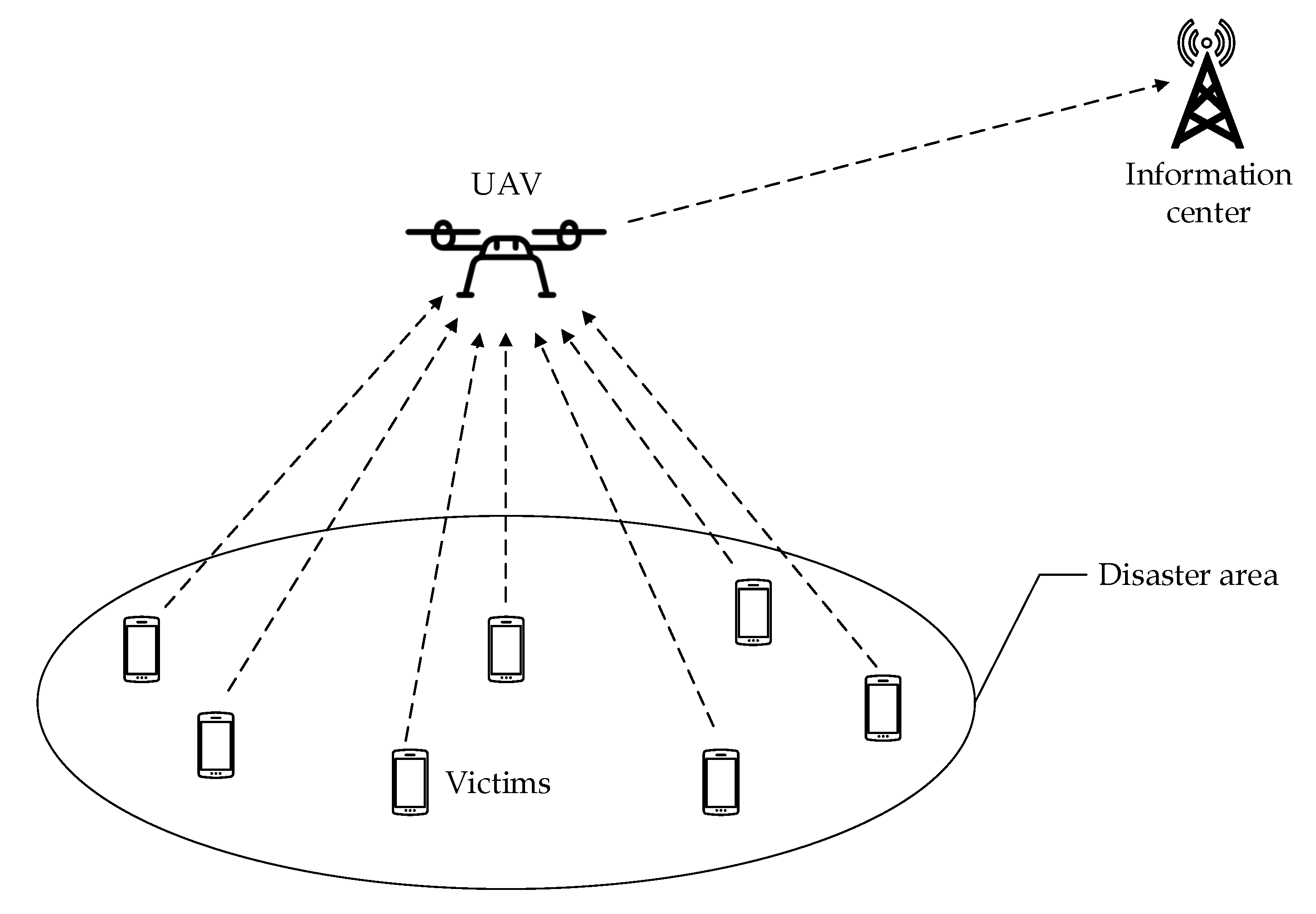
25]. In our paper, we consider a disaster scenario where a UAV is deployed within the affected area to relay the data from N ground victims to a remote information centre for coordinating search and rescue missions as the terrestrial infrastructure connecting the affected area and the information centre is damaged, as illustrated in Figure 1. The location of the nth victim is denoted by c n R 2 × 1 . The UAV is dispatched to collect data from the victims for a duration of T seconds. We assume that the UAV flies at a fixed altitude of H meters and we denote its maximum speed as V max in meters/second (m/s). The initial and final locations of the UAV are assumed to be pre-determined, whose horizontal coordinates are denoted as c I , c F R 2 × 1 , respectively. We assume that | | c F c I | | V max T such that there exists at least one feasible trajectory for the UAV to follow.
In this paper, we aim to optimize the transmission throughput from ground victims to the UAV, by jointly adjusting the wireless bandwidth scheduling and UAV trajectory. This is considered as a form of trajectory and communication resource allocation co-design problem in Reference [4]. Such problems can be first converted into more tractable forms with a finite number of optimization variables by trajectory discretization [4,18,20], and then utilize the more general optimization framework with Block Coordinate Descent (BCD) and Successive Convex Approximation (SCA) techniques to deal with the non-convexity [4]. Two trajectory discretization techniques, the time discretization and path discretization, are introduced in Reference [4], together with a comparison of them. Since time discretization has the advantages of equal time slot length, linear state-space representation, and the mission completion time T is assumed to be known. Therefore time discretization is considered here.
For convenience, T is equally divided into K time slots, such that T = K δ t , where δ t denotes the elemental slot length such that the UAV’s location is considered unchanged by the ground victims during this time even at the maximum speed. Therefore, the UAV’s trajectory can be approximated by the sequence { c [ k ] , k { 1 , , K , K + 1 } } , where c [ k ] denotes the UAV’s location at time slot k. To be specific, c [ 1 ] , c [ K + 1 ] corresponds to the initial and final locations of the UAV respectively, that is, c [ 1 ] = c I , c [ K + 1 ] = c F .
We compare the data transmission performance of the system when the DS method is enabled or disabled. We assume the total bandwidth of the system and the transmission power of each victim are the same. When DS is disabled, we consider two bandwidth allocation mechanisms. One is a fair allocation scheme [19]. We assume N different sub-carriers with the same bandwidth W are fairly allocated to the N victims to avoid interference during the period T. The other is a bandwidth contention scheme [18,20]. We assume the overall bandwidth N W is occupied by one victim for data transmission during each time slot.
When DS is enabled, due to the limitations of transmission synchronisation and processing complexity, we assume during each time slot only transmissions from one pair of victims can be supported. In order to ensure the proper functioning of the DS method, the signal level received by the UAV from the supported victims are kept the same [22]. Meanwhile, during each time slot, the non-DS supported victims are allocated with bandwidth W each. The supported victims can both transmit in the remaining bandwidth N W ( N 2 ) W = 2 W simultaneously [22]. Therefore, we denote the bandwidth scheduling variable as a n [ k ] = 2 if victim n is supported by DS at time slot k, and a n [ k ] = 1 if victim n is not supported by DS, where k { 1 , , K } .
The following statements relate to the DS enabled scheme. The distance between the UAV and victim n { 1 , , N } at time slot k { 1 , , K } is given by
d n [ k ] = | | c [ k ] c n | | 2 + H 2 .
We use P to denote the transmission power of a victim. Furthermore, we assume that the channels from the victims to the UAV are dominated by LoS links. Thus, the channel power gain between victim n and the UAV in time slot k is given by
h n [ k ] = β 0 d n 2 [ k ] = β 0 | | c [ k ] c n | | 2 + H 2 ,
where β 0 represents the channel power gain at a reference distance of unit length. The maximum achievable data rate in bits/s/Hz for victim n at time slot k with respect to the sub-carrier bandwidth W is given by
R n [ k ] = a n [ k ] log 2 ( 1 + P h n [ k ] σ 2 ) ,
where σ 2 is the power of the Additive White Gaussian Noise (AWGN). For the DS supported victims, the transmission bandwidth is 2 W . Since the noise power spectrum density is the same, the received noise power at the UAV is twice as that for a non-DS supported victim. However, the UAV treats the overlapping signal as the effective received signal [22], hence doubling the received signal power. As a result, the received SNR at the UAV for a DS supported victim is same as that for a non-DS supported victim.Thus, the average achievable data rate from victim n to the UAV is denoted as
R n = 1 K k = 1 K R n [ k ] .
Note that, for each victim, R n δ t K is the overall data throughput. As δ t and K are constants, thus the average achievable data rate R n is equivalent to the overall throughput.
Additionally, in this problem, the bandwidth scheduling variables set is A = { a n [ k ] , n , k } , and the UAV’s trajectory location variables set is C = { c [ k ] , k } .

3. Problem Formulation

For efficient transmission, whilst considering fairness among all the victims, we aim to maximize the minimum average data rate relayed by the UAV among all N victims. That is
max A , C R ,
subject to
R n R , n
n = 1 N a n [ k ] N + 2 , k
a n [ k ] { 1 , 2 } , n , k
P h i [ k ] = P h j [ k ] , k , ( a i [ k ] = a j [ k ] = 2 , i j )
| | c [ k + 1 ] c [ k ] | | V max δ t , k { 1 , , K }
c [ 1 ] = c I , c [ K + 1 ] = c F ,
where R is the objective average data rate to be maximized. (5a) represents the minimum average data rate among all the victims. (5b) assumes that one pair of victims can be supported by the DS method during each time slot. (5c) considers that a victim can be either supported by the DS method or not. (5d) means that for the DS method supported victims, their received signal power at the UAV are kept the same [22]. (5e) means that the maximum traverse distance of the UAV is limited by its maximum flying speed during each time slot. In addition, (5f) shows the pre-determined initial and final locations of the UAV trajectory.

4. Proposed Solution

In this section, an iterative algorithm based on the general optimization framework mentioned in Section 2 for solving the problem (5) subject to constraints (5a)–(5f) is discussed. The overall problem is separated into two sub-problems based on BCD. To be specific, for a given UAV trajectory C , we optimize the victim bandwidth scheduling A . On the other hand, for any given victim bandwidth scheduling A , the UAV trajectory C is optimized with the help of SCA. Furthermore, to ensure the best decoding performance of the DS method by the UAV, the received signal power from the paired victims are the same, as stated in (5d). We call this the power balance and it is implemented to link the two sub-problems. Finally, the overall algorithm is presented as a combination of the two sub-problems and power balance.

4.1. Victim Bandwidth Scheduling Optimization

For any given UAV trajectory C , problem (5) is simplified as
max A R ,
subject to
R n R , n
n = 1 N a n [ k ] N + 2 , k
a n [ k ] { 1 , 2 } , n , k
Sub-problem (6) is hard to solve as the optimization variable A involves integers. To solve this sub-problem, we first relax the integer variable restriction in (6c), allowing for continuous variables, which results in the following sub-problem
max A R ,
subject to
R n R , n
n = 1 N a n [ k ] N + 2 , k
1 a n [ k ] 2 , n , k .
Such a relaxation in general suggests that the objective value of sub-problem (7) serves as an upper bound for that of sub-problem (6). (7) is a standard linear programming problem, which can be solved by the CVX toolbox [26] in MATLAB. Later in the description of the overall algorithm, we explain how to construct a solution for problem (5) based on solving sub-problem (7).

4.2. UAV Trajectory Optimization

For any given victim bandwidth scheduling A , problem (5) is simplified as
max C R ,
subject to
R n R , n
| | c [ k + 1 ] c [ k ] | | V max δ t , k { 1 , , K }
c [ 1 ] = c I , c [ K + 1 ] = c F ,
The constraint (8a) is equivalent to the following expression
1 K k = 1 K a n [ k ] log 2 ( 1 + P γ 0 | | c [ k ] c n | | 2 + H 2 ) R , n ,
where γ 0 β 0 σ 2 . Note that (8a) is a non-convex constraint regarding the UAV trajectory variable c [ k ] . To deal with it, the expression in (8a) is replaced by its lower bound at a given local point. We denote the input UAV trajectory for sub-problem (7) as { c [ k ] , k { 1 , , K , K + 1 } } . Recalling that the logarithmic function is lower bounded by its first order Taylor expansion, we can obtain the following lower bound with the given local point c [ k ] when treating | | c [ k ] c n | | 2 as the variable
R n [ k ] = a n [ k ] log 2 ( 1 + P γ 0 | | c [ k ] c n | | 2 + H 2 ) a n [ k ] A n [ k ] ( | | c [ k ] c n | | 2 | | c [ k ] c n | | 2 ) + B n [ k ] R n l b [ k ] ,
where
A n [ k ] = P γ 0 log 2 e ( | | c [ k ] c n | | 2 + H 2 ) ( | | c [ k ] c n | | 2 + H 2 + P γ 0 )
B n [ k ] = log 2 ( 1 + P γ 0 | | c [ k ] c n | | 2 + H 2 ) , n , k .
With the lower bound (9), sub-problem (8) is approximated as the following sub-problem
max C R l b ,
subject to
R n l b = 1 K k = 1 K R n l b [ k ] R l b , n
| | c [ k + 1 ] c [ k ] | | V max δ t , k { 1 , , K }
c [ 1 ] = c I , c [ K + 1 ] = c F ,
For (10a) the victim bandwidth scheduling variable a n [ k ] is determined by solving the sub-problem (7). Hence both (10a) and (10b) are convex quadratic constraints and (10c) is a linear constraint. Therefore, sub-problem (10) is a convex quadratically constrained quadratic program which can also be solved efficiently by the MATLAB CVX toolbox.

4.3. Power Balance

A power balance mechanism is implemented to ensure the signal power received at the UAV from the DS supported victims are the same during each time slot, as presented by (5d). Upon solving sub-problem (7), the victim bandwidth scheduling variable is determined. As the transmission power for the paired victims are both P, therefore when the UAV locates at a position where its distances to the paired victims are same, the received power can be balanced. In order to obtain such UAV’s position, the coefficients A n [ k ] and B n [ k ] in constraint (10a) should be pre-adjusted to be the same. Power balance is the operation of coefficients pre-adjustments, which is implemented to connect sub-problems (7) and (10).

4.4. Overall Algorithm

Based on the results of the two sub-problems (7) and (10), we construct an overall iterative algorithm for problem (5). Specifically, during each iteration, the victim bandwidth scheduling A and UAV flight trajectory C are alternately optimized, by solving each sub-problem (7) or (10) in turn whilst maintaining the other variables unchanged. Moreover, the trajectory achieved in each iteration is used as the input to the next iteration. The details of the algorithm are provided in Algorithm 1. As stated, power balance is implemented to connect the two sub-problems. Furthermore, at the end of the algorithm, we construct the optimal integer victim bandwidth scheduling from the continuous values calculated by the iterative approach.
Algorithm 1 Iterative solution for problem (5)
1:
Initialize the UAV trajectory, and denote it as C 0 .
2:
Denote the iteration number variable as g, and let g = 0 .
3:
repeat
4:
 Solve sub-problem (7) for given C g , and denote the optimal solution as A g + 1 .
5:
 Execute power balance.
6:
 Solve sub-problem (10) for given A g + 1 , C g , and denote the optimal solution as C g + 1 .
7:
 Update g = g + 1 .
8:
until The increase of the objective value is below a threshold t h .
9:
Treat the optimal solution C g + 1 for the last iteration as the optimal UAV trajectory.
10:
Construct the optimal victim bandwidth scheduling based on the optimal solution A g + 1 for the last iteration.
In the solution obtained by Algorithm 1, if the victim bandwidth scheduling variables a n [ k ] are all integer, then the obtained solution is a feasible solution of problem (5). Otherwise, for all the non-integer a n [ k ] , the range for the value should be 1 < a n [ k ] < 2 . We denote the fractional part as b n [ k ] = a n [ k ] 1 . During each time slot δ t , we can regard the expectation of the victim bandwidth scheduling as a n [ k ] . Thus, for a specific victim with given a n [ k ] , in the period of δ t b n [ k ] the bandwidth scheduling is configured as 2, and in the remaining period δ t ( 1 b n [ k ] ) , the bandwidth scheduling is configured as 1. Therefore, the integer victim bandwidth scheduling is constructed based on the non-integer value. If the bandwidth is allocated explicitly, it permits an integer solution with zero relaxation gap.
Next, we discuss the convergence of Algorithm 1 as follows. We first define the objective variable R as a function of A and C , that is R = η ( A , C ) . In step 4 of Algorithm 1, since the optimal solution of sub-problem (7) is obtained for given C g , we have
η ( A g , C g ) η ( A g + 1 , C g ) .
Then for given A g + 1 and C g in step 6 of Algorithm 1, it follows that
η ( A g + 1 , C g ) η l b , g ( A g + 1 , C g + 1 )
η l b , g ( A g + 1 , C g + 1 ) η ( A g + 1 , C g + 1 ) ,
where (12a) holds since η ( A g + 1 , C g ) has the same objective value as η l b , g ( A g + 1 , C g ) at the given point C g , and η l b , g ( A g + 1 , C g ) η l b , g ( A g + 1 , C g + 1 ) since at Step 6 of Algorithm 1 with given A g + 1 , sub-problem (10) is solved optimally with solution C g + 1 . (12b) holds because for any iteration g, η l b , g ( A g , C g ) is always a lower bound of η ( A g , C g ) for any A and C . Based on (11), (12a) and (12b), we obtain η ( A g , C g ) η ( A g + 1 , C g + 1 ) , which means that the objective value of problem (5) is non-decreasing after each iteration of Algorithm 1. As the objective value of problem (5) is upper bounded by a finite value, Algorithm 1 is therefore convergent.
The proposed Algorithm 1 is based on the general state-of-the-art optimization framework consisting of BCD and SCA, together with a novel mechanism, named power balance, to handle the feasibility requirement of the DS method.

5. Numerical Results

In this paper, the main metric to assess the system is the average data rate among all the victims which is expressed in units of bits/s/Hz. With a higher average data rate, more throughput can be achieved for the victims. Additionally, the victim bandwidth scheduling and the UAV optimal flight trajectory are also metrics for evaluating the system performance.
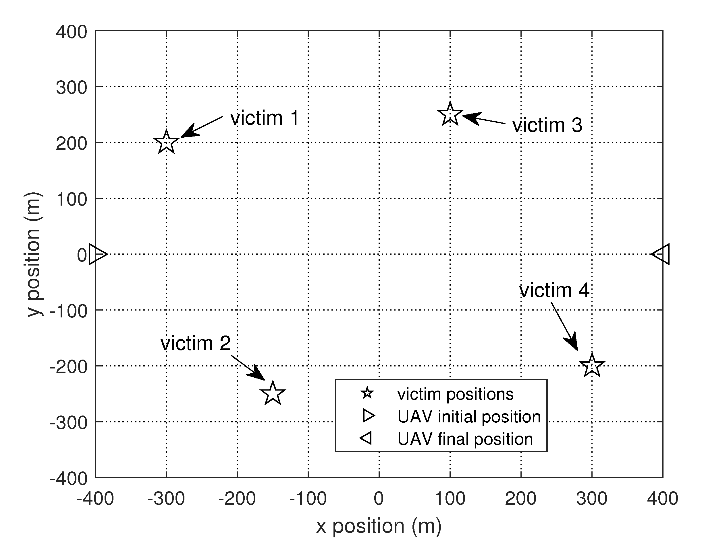
We consider a system with N = 4 victims that are located within an area of size 800 × 800 m2 as illustrated in Figure 2. The UAV is assumed to fly at a fixed altitude of H = 100 m. The receiver noise power is assumed to be σ 2 = 110 dBm. The channel power gain at the reference distance of unit length is set to β 0 = 50 dB. The transmit power for the victim is set to P = 0.1 W and the maximum flight speed of the UAV is set to V max = 50 m/s [20]. The elemental time slot is set to be δ t = 0.5 s [18]. The threshold to control the iteration of the solution algorithm is set as t h = 10 2 .
In this section, we compare the DS scheme with non-DS schemes comprising fair bandwidth allocation and bandwidth contention mechanisms. It should be noted that the bandwidth contention mechanism problem is solved by the BCD-SCA optimization framework. The fair bandwidth allocation mechanism problem is solved assuming fixed bandwidth scheduling. The DS scheme is solved by the BCD-SCA optimization framework, together with the power balance technique.
We first list the optimal max-min average data rate for the different schemes for various total period values T in Table 1. 
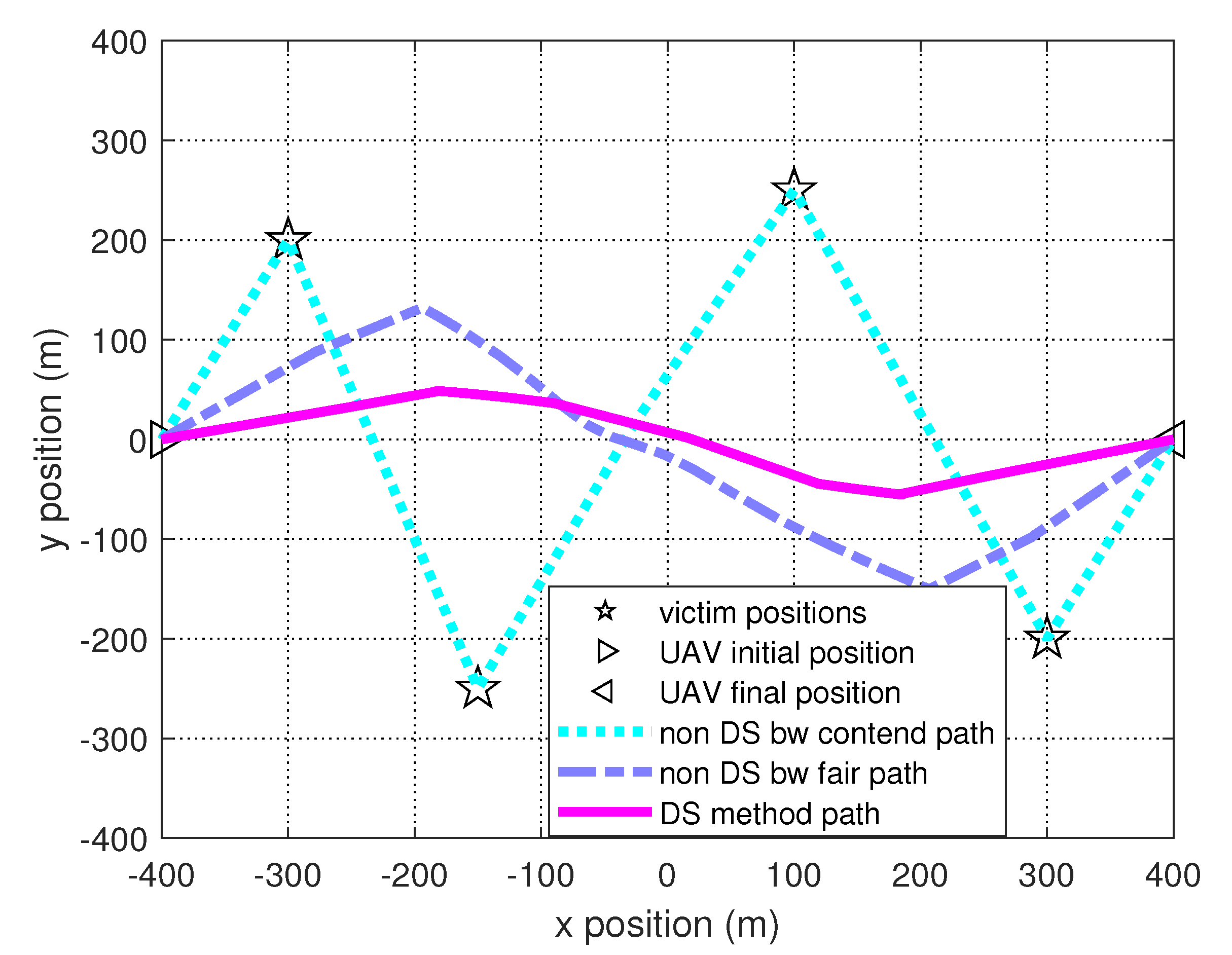
Figure 3 shows the optimal UAV flight trajectories for the different schemes when T = 60 s. The DS method has the best performance in terms of average data rate, since the bandwidth is multiplexed by a pair of victims in each time slot. The non-DS bandwidth contention scheme has better throughput performance than the non-DS fair bandwidth allocation scheme as the UAV flies to and hovers above each victim in the bandwidth contention scheme, which brings better channel gain for data transmission.
Furthermore, we analyse the theoretical optimal max-min average data rate for the DS scheme under different T, as shown in the last row of Table 1. The theoretical values for the scenario shown in Figure 2 are feasible to calculate. Within time T, the UAV should spend the most time supporting the DS enabled victims, and spend the least time traversing from the initial position to the final position. To be specific, the UAV should traverse at its maximum speed, and for the remaining time hover at two positions, one is the midpoint of line segment victim1–victim2, and the other is the midpoint of line segment victim3–victim4. By letting the UAV hover at the midpoint, it is able to maximize the received signal power at the UAV for the paired DS enabled victims. From a comparison of the results, we can see that the proposed solution is very close to the theoretical values, which shows the correctness and feasibility of our proposed approach. In addition, the proposed technique can be treated as a general method to solve the DS enabled UAV trajectory planning problem. Since the theoretical analysis is not always easy to undertake, due to the complex network topology, the proposed approach provides a practical way to get close to the ground true optimal value.
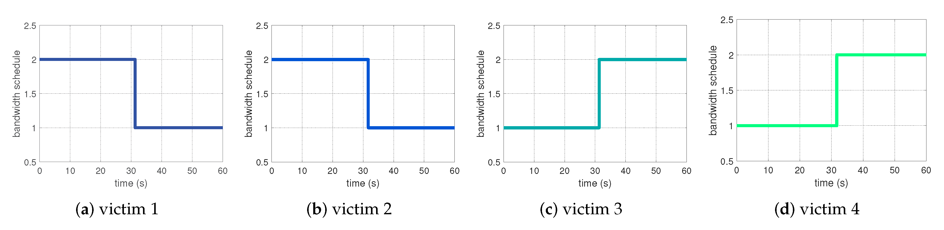
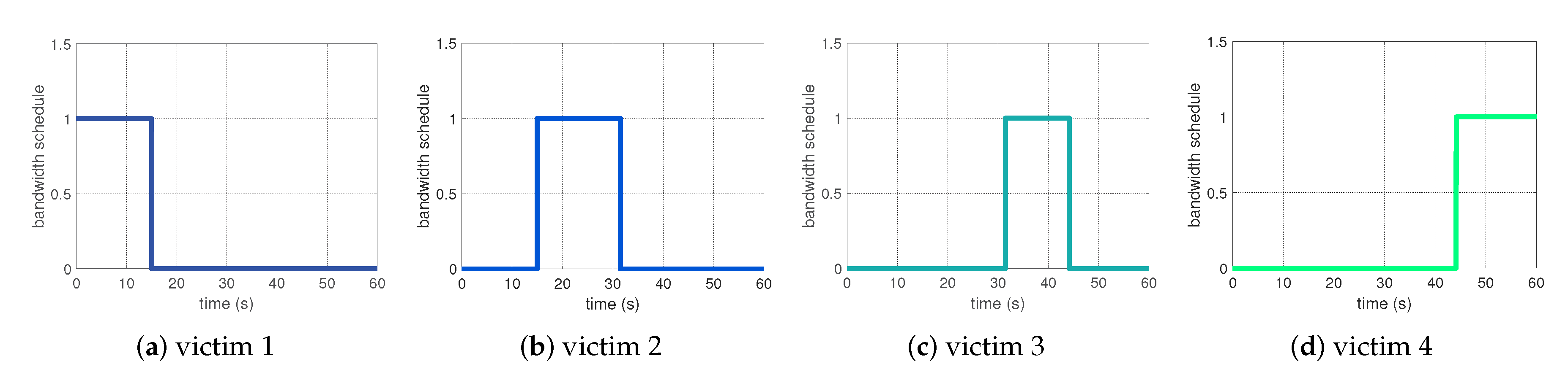
Figure 4 and Figure 5 show the bandwidth schedule for each victim in the DS method and non-DS bandwidth contention scheme, respectively. In the DS scheme, victim 1 and victim 2 are supported by the DS method first, then victim 3 and victim 4 are supported by the DS method. However, in the non-DS bandwidth contention scheme, from victim 1 to victim 4, each of them occupies the bandwidth sequentially. The bandwidth schedule configurations are delivered to the victims by the UAV via control signals.
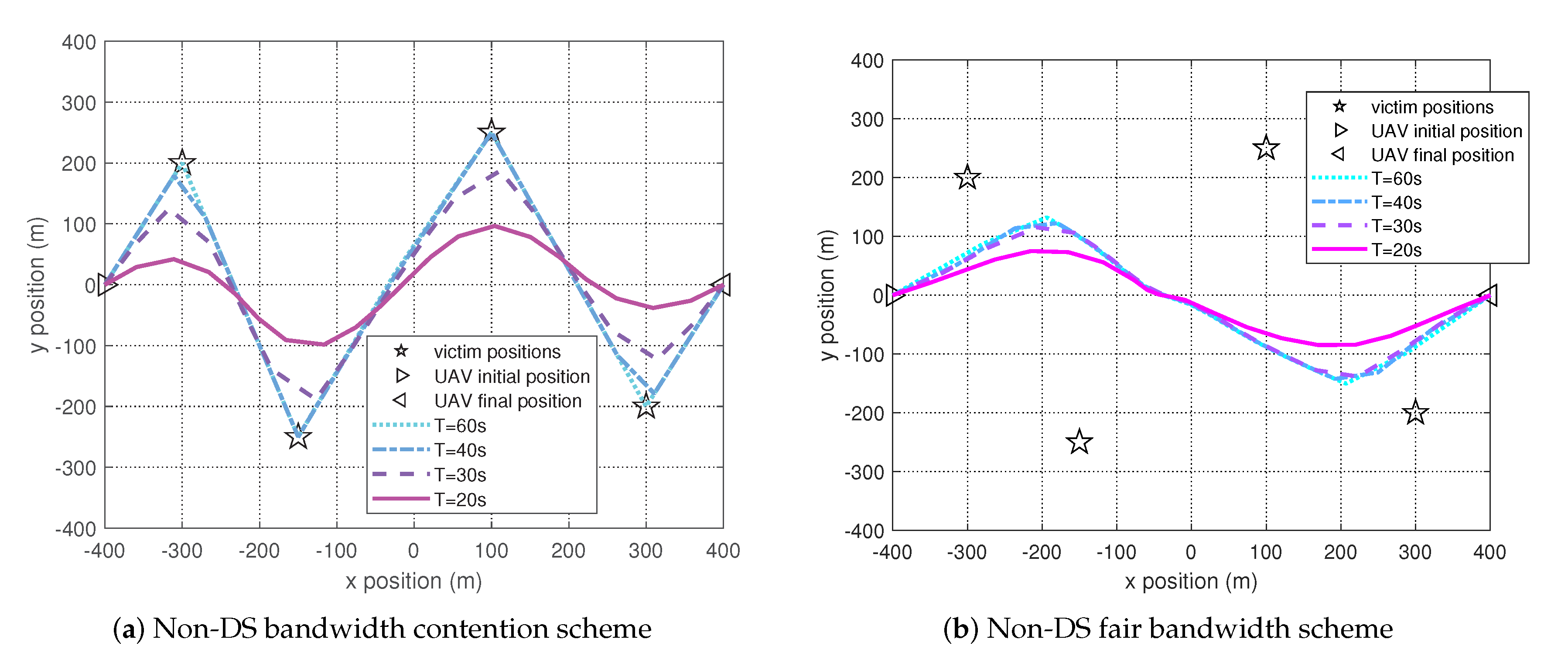
Figure 6a shows the optimal trajectories for the non-DS bandwidth contention scheme for different T values. As the period T decreases, the maximum distance that the UAV can traverse between the initial and final positions decreases, thus the UAV flight trajectory eventually becomes unable to reach every victim. However, the UAV tries to approach each victim as close as possible. Meanwhile, the channel gain worsens as the distance between the UAV and victim is increasing, hence resulting in a decrease of the optimal max-min average data rate.
Figure 6b shows the optimal trajectories for the non-DS fair bandwidth allocation scheme for different T values. The optimal average data rate for the non-DS fair bandwidth allocation scheme decreases slightly as the period T decreases. This is because that in the non-DS fair bandwidth allocation scheme, the UAV flies along a trajectory where the distances from each victim to the UAV do not vary much. The length of the resulting trajectory is covered by the maximum UAV traverse distance under different T. Therefore the change of T slightly changes the optimal UAV flight trajectory.
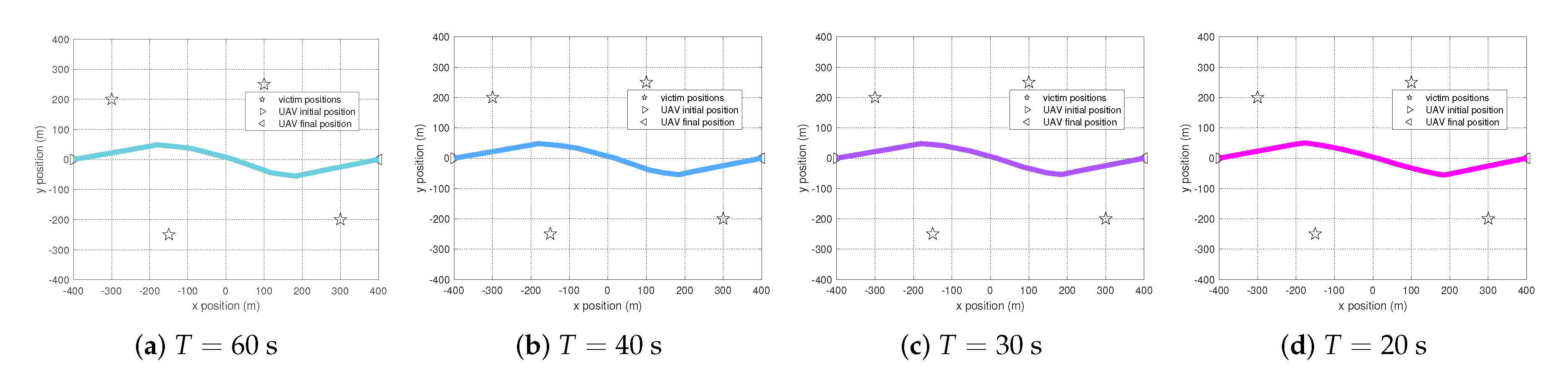
Figure 7 shows the optimal trajectories for the DS method for different T values. The change of the period T only changes the optimal average data rate slightly. In the DS method, the UAV is likely to fly at the positions that are the same distance to both of the DS supported paired victims, as discussed in the theoretical analysis. The maximum UAV traverse distance under different T values can cope with this kind of trajectory. Hence the change of T only slightly affects the UAV flying trajectory.
Next, we compare the propulsion energy consumed by the UAV for different schemes. As derived in Reference [27], the propulsion power consumption for a rotary-wing UAV in a time slot can be modelled as
P [ k ] = P 0 ( 1 + 3 v [ k ] 2 U tip 2 ) + P i ( 1 + v [ k ] 4 4 v 0 4 v [ k ] 2 2 v 0 2 ) 1 / 2 + 1 2 d 0 ρ s A v [ k ] 3 ,
where v [ k ] is the constant flight speed of the UAV in a time slot. P 0 and P i represent the blade profile power and induced power in hovering status, respectively. U tip denotes the tip speed of the rotor blade, v 0 is known as the mean rotor induced velocity in hover, and d 0 and s are the fuselage drag ratio and rotor solidity, respectively. ρ and A denote the air density and rotor disc area, respectively. Therefore, the propulsion energy in a time slot is P [ k ] δ t . Furthermore, the overall propulsion energy of the UAV is
E = k = 1 K P [ k ] δ t .
We assume that P 0 = 577.3 W, P i = 793.0 W, U tip = 200 m/s, v 0 = 7.21 m/s, d 0 = 0.3 , ρ = 1.225 kg/m3, s = 0.05 , and A = 0.79 m2 [28]. Based on the optimal UAV trajectory derived for different schemes, the overall propulsion energy consumed by the UAV is listed in Table 2. On observing the results, for shorter time periods, that is when T = 40 s, 30 s, and 20 s, the DS method consumes most propulsion energy, while the non-DS fair bandwidth allocation scheme consumes least propulsion energy. In the DS method, the UAV hovers for the longest time, and in the two non-DS schemes, it hovers for much less time. When the UAV flying speed is less than around 40 m/s, it consumes most power when remains in the hovering status [28]. This is why the UAV consumes most propulsion energy in the DS method. However, for a longer time period, when T = 60 s, the non-DS bandwidth contention scheme consumes most propulsion energy. This is because the UAV hovers at the position of each victim sequentially. The DS method consumes more energy than the non-DS fair bandwidth allocation scheme, but with higher max-min average data rate among all the victims.
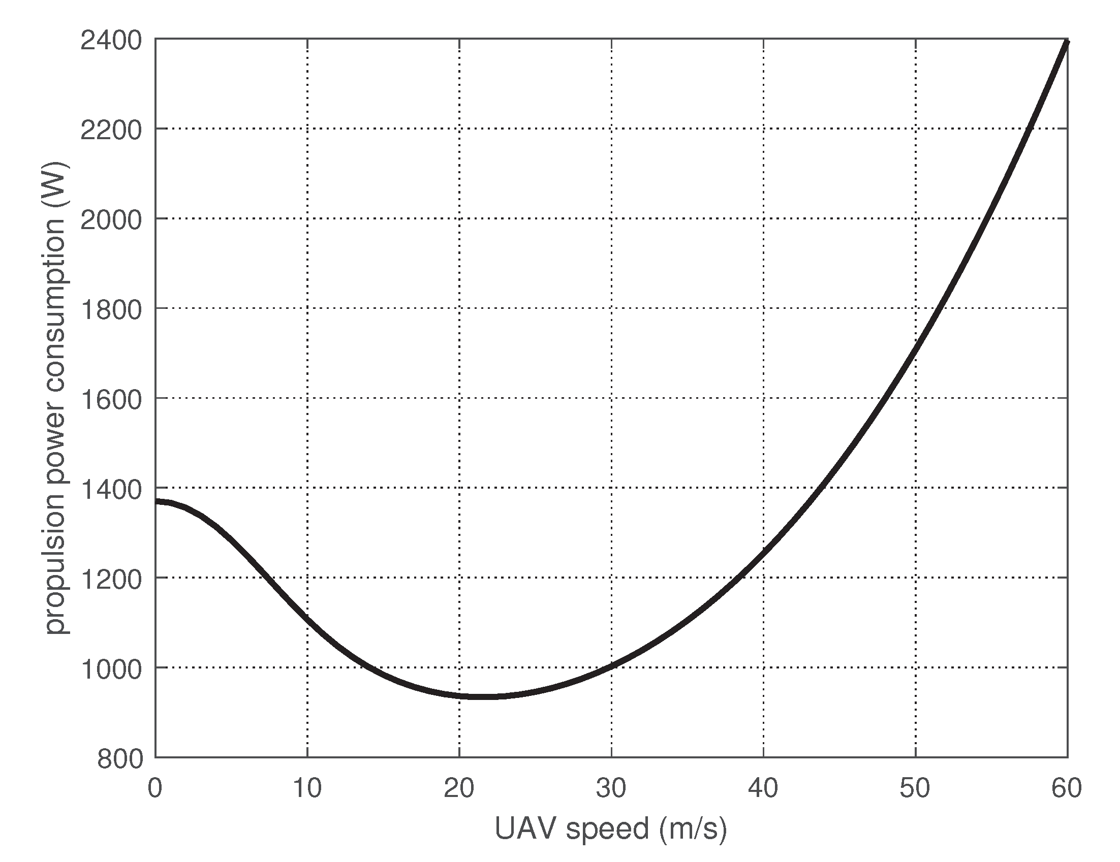
To better understand the relationship of propulsion power and the speed of UAV, we plot Figure 8 with the same parameters configured in the simulation. By observing the curve, the minimum power consumption is at a UAV speed of around 20 m/s rather than when hovering, at 0 m/s. Hence in order to reduce the propulsion energy consumption for the DS method, we replace the hovering status with a circular movement with a relative small radius at a speed of 20 m/s. By providing a small angular UAV movement, the propulsion energy needed to provide sufficient lift is appreciably reduced as shown in the last row of Table 2.

6. Conclusions

In this paper, we consider a dual sampling bandwidth efficient transmission technique in regard to the UAV flight trajectory, so as to maximize the minimum data transmission throughput among all the victims. In order to solve the problem, we propose an iterative algorithm which alternately optimizes the victim bandwidth scheduling and UAV trajectory. In addition, power balance is implemented in each iteration of the algorithm for supporting the DS method. We compare the DS scheme with two non-DS schemes, that is, a fair bandwidth allocation scheme and a bandwidth contention scheme. The DS scheme outperforms the non-DS schemes in terms of the optimal max-min average data rate among all the victims. The theoretical analysis reveals that the proposed solution is very close to the ground true optimal value. The optimal UAV flight trajectory for the DS scheme is different from the non-DS bandwidth contention scheme and non-DS fair bandwidth allocation scheme, as the UAV flies to positions that are not necessarily close to each victim. The UAV trajectory derived by the proposed algorithm is pre-configured before the UAV is dispatched and we assume the UAV is explicitly guided to follow the optimal trajectory. In regard to the UAV propulsion energy consumption, for shorter time periods, the non-DS fair bandwidth allocation scheme consumes the least energy. For longer time periods, the DS method consumes the second least energy but achieves the highest max-min average data rate among all victims. However, if the UAV hovering episodes are replaced by small circular movements, the propulsion energy consumption for DS method can be significantly reduced.
Moreover, the assumption that the UAV starts and ends at fixed locations is reasonable. As in a disaster scenario, maybe only some certain places are able for launching and landing the UAV. In addition, a feasible path can be either a straight line, a circular curve or in other types, as long as the UAV can follow this path to fly through the area to connect all the victims. Meanwhile, a feasible path helps the staff collect the UAV back.

Author Contributions

Conceptualization, F.J.; methodology, F.J.; software, F.J.; validation, F.J.; writing—original draft preparation, F.J.; writing—review and editing, C.P.; supervision, C.P. All authors have read and agreed to the published version of the manuscript.

Funding

This research received no external funding.

Conflicts of Interest

The authors declare no conflict of interest.

Abbreviations

The following abbreviations are used in this manuscript:
UAVUnmanned Aerial Vehicle
DSDual Sampling
LoSLine-of-Sight
BSBase Station
BCDBlock Coordinate Descent
SCASuccessive Convex Approximation

References

  1. Zeng, Y.; Zhang, R.; Lim, T.J. Wireless communications with unmanned aerial vehicles: Opportunities and challenges. IEEE Commun. Mag. 2016, 54, 36–42. [Google Scholar] [CrossRef] [Green Version]
  2. Sharma, V. Advances in Drone Communications, State-of-the-Art and Architectures. Drones 2019, 3, 21. [Google Scholar] [CrossRef] [Green Version]
  3. Basso, M.; Zacarias, I.; Tussi Leite, C.E.; Wang, H.; Pignaton de Freitas, E. A Practical Deployment of a Communication Infrastructure to Support the Employment of Multiple Surveillance Drones Systems. Drones 2018, 2, 26. [Google Scholar] [CrossRef] [Green Version]
  4. Zeng, Y.; Wu, Q.; Zhang, R. Accessing From the Sky: A Tutorial on UAV Communications for 5G and Beyond. Proc. IEEE 2019, 107, 2327–2375. [Google Scholar] [CrossRef] [Green Version]
  5. Fotouhi, A.; Qiang, H.; Ding, M.; Hassan, M.; Giordano, L.G.; Garcia-Rodriguez, A.; Yuan, J. Survey on UAV Cellular Communications: Practical Aspects, Standardization Advancements, Regulation, and Security Challenges. IEEE Commun. Surv. Tutor. 2019, 21, 3417–3442. [Google Scholar] [CrossRef] [Green Version]
  6. Chen, X.; Hu, X.; Zhu, Q.; Zhong, W.; Chen, B. Channel modeling and performance analysis for UAV relay systems. China Commun. 2018, 15, 89–97. [Google Scholar]
  7. Dan, Z.; Wu, X.; Zhu, S.; Zhuang, T.; Wang, J.Y. On the Outage Performance of Dual-Hop UAV Relaying with Multiple Sources. In Proceedings of the 2019 Cross Strait Quad-Regional Radio Science and Wireless Technology Conference (CSQRWC), Taiyuan, China, 19–22 July 2019; pp. 1–3. [Google Scholar]
  8. Khan, M.A.; Qureshi, I.M.; Khanzada, F. A Hybrid Communication Scheme for Efficient and Low-Cost Deployment of Future Flying Ad-Hoc Network (FANET). Drones 2019, 3, 16. [Google Scholar] [CrossRef] [Green Version]
  9. Li, Y.; Liao, C.; Wang, Y.; Wang, C. Energy-Efficient Optimal Relay Selection in Cooperative Cellular Networks Based on Double Auction. IEEE Trans. Wirel. Commun. 2015, 14, 4093–4104. [Google Scholar] [CrossRef]
  10. An, K.; Li, Y.; Yan, X.; Liang, T. On the Performance of Cache-Enabled Hybrid Satellite-Terrestrial Relay Networks. IEEE Wirel. Commun. Lett. 2019, 8, 1506–1509. [Google Scholar] [CrossRef]
  11. Sun, X.; Yang, W.; Cai, Y.; Xiang, Z.; Tang, X. Secure Transmissions in Millimeter Wave SWIPT UAV-Based Relay Networks. IEEE Wirel. Commun. Lett. 2019, 8, 785–788. [Google Scholar] [CrossRef]
  12. Ruan, L.; Wang, J.; Chen, J.; Xu, Y.; Yang, Y.; Jiang, H.; Zhang, Y.; Xu, Y. Energy-efficient multi-UAV coverage deployment in UAV networks: A game-theoretic framework. China Commun. 2018, 15, 194–209. [Google Scholar] [CrossRef]
  13. Zhang, X.; Duan, L. Fast Deployment of UAV Networks for Optimal Wireless Coverage. IEEE Trans. Mob. Comput. 2019, 18, 588–601. [Google Scholar] [CrossRef] [Green Version]
  14. Mozaffari, M.; Saad, W.; Bennis, M.; Debbah, M. Drone Small Cells in the Clouds: Design, Deployment and Performance Analysis. In Proceedings of the 2015 IEEE Global Communications Conference (GLOBECOM), San Diego, CA, USA, 6–10 December 2015; pp. 1–6. [Google Scholar]
  15. Mozaffari, M.; Saad, W.; Bennis, M.; Debbah, M. Efficient Deployment of Multiple Unmanned Aerial Vehicles for Optimal Wireless Coverage. IEEE Commun. Lett. 2016, 20, 1647–1650. [Google Scholar] [CrossRef]
  16. Sánchez-García, J.; García-Campos, J.M.; Toral, S.L.; Reina, D.G.; Barrero, F. An Intelligent Strategy for Tactical Movements of UAVs in Disaster Scenarios. Int. J. Distrib. Sens. Netw. 2016, 12, 8132812. [Google Scholar] [CrossRef] [Green Version]
  17. Lyu, J.; Zeng, Y.; Zhang, R. Cyclical Multiple Access in UAV-Aided Communications: A Throughput-Delay Tradeoff. IEEE Wirel. Commun. Lett. 2016, 5, 600–603. [Google Scholar] [CrossRef] [Green Version]
  18. Zhan, C.; Zeng, Y.; Zhang, R. Energy-Efficient Data Collection in UAV Enabled Wireless Sensor Network. IEEE Wirel. Commun. Lett. 2017, 7, 328–331. [Google Scholar] [CrossRef] [Green Version]
  19. Cai, Y.; Wei, Z.; Li, R.; Ng, D.W.K.; Yuan, J. Energy-Efficient Resource Allocation for Secure UAV Communication Systems. In Proceedings of the IEEE WCNC 2019, Marrakech, Morocco, 15–19 April 2019. [Google Scholar]
  20. Wu, Q.; Zeng, Y.; Zhang, R. Joint Trajectory and Communication Design for UAV-Enabled Multiple Access. In Proceedings of the GLOBECOM 2017—2017 IEEE Global Communications Conference, Singapore, 4–8 December 2017; pp. 1–6. [Google Scholar]
  21. Fadlullah, Z.M.; Takaishi, D.; Nishiyama, H.; Kato, N.; Miura, R. A dynamic trajectory control algorithm for improving the communication throughput and delay in UAV-aided networks. IEEE Netw. 2016, 30, 100–105. [Google Scholar] [CrossRef]
  22. Jiang, F.; Sun, Y.; Phillips, C. A Dual Sampling Cooperative Communication Method for Energy and Delay Reduction. In Proceedings of the 2018 IEEE 16th International Conference on Dependable, Autonomic and Secure Computing, 16th International Conference on Pervasive Intelligence and Computing, 4th International Conference on Big Data Intelligence and Computing and Cyber Science and Technology Congress (DASC/PiCom/DataCom/CyberSciTech), Athens, Greece, 12–15 August 2018; pp. 822–827. [Google Scholar]
  23. Jiang, F.; Sun, Y.; Phillips, C. Cache Migration Protocol for Information-Centric Networks. In Proceedings of the 2019 IEEE Wireless Communications and Networking Conference Workshop (WCNCW), Marrakech, Morocco, 15–18 April 2019; pp. 1–6. [Google Scholar]
  24. Yang, D.; Wu, Q.; Zeng, Y.; Zhang, R. Energy Tradeoff in Ground-to-UAV Communication via Trajectory Design. IEEE Trans. Veh. Technol. 2018, 67, 6721–6726. [Google Scholar] [CrossRef] [Green Version]
  25. Erdelj, M.; Król, M.; Natalizio, E. Wireless Sensor Networks and Multi-UAV systems for natural disaster management. Comput. Netw. 2017, 124, 72–86. [Google Scholar] [CrossRef]
  26. MATLAB CVX Toolbox. Available online: http://cvxr.com/cvx/ (accessed on 27 October 2020).
  27. Zeng, Y.; Xu, J.; Zhang, R. Energy Minimization for Wireless Communication With Rotary-Wing UAV. IEEE Trans. Wirel. Commun. 2019, 18, 2329–2345. [Google Scholar] [CrossRef] [Green Version]
  28. Zeng, Y.; Xu, J.; Zhang, R. Rotary-Wing UAV Enabled Wireless Network: Trajectory Design and Resource Allocation. In Proceedings of the 2018 IEEE Global Communications Conference (GLOBECOM), Abu Dhabi, UAE, 9–13 December 2018; pp. 1–6. [Google Scholar]
Figure 1. An Unmanned Aerial Vehicle (UAV)-aided wireless communication system in a disaster scenario.
Futureinternet 12 00193 g001
Figure 2. A disaster scenario topology.
Futureinternet 12 00193 g002
Figure 3. Comparison of optimal max-min average data rate UAV trajectories for T = 60 s.
Futureinternet 12 00193 g003
Figure 4. Dual Sampling (DS) method bandwidth schedule for T = 60 s.
Futureinternet 12 00193 g004
Figure 5. Non-DS method bandwidth contention schedule for T = 60 s.
Futureinternet 12 00193 g005
Figure 6. Non-DS schemes optimal UAV trajectory comparison.
Futureinternet 12 00193 g006
Figure 7. DS method optimal trajectories comparison.
Futureinternet 12 00193 g007
Figure 8. UAV propulsion power consumption.
Futureinternet 12 00193 g008
Table 1. Comparison of optimal max-min average achievable data rate (bits/s/Hz).
T = 60  s T = 40  s T = 30  s T = 20  s
non-DS bandwidth contention scheme10.409.999.639.12
non-DS fair bandwidth allocation scheme9.809.789.769.71
DS method14.6514.6414.6214.58
DS method (theoretical analysis)14.7014.6714.6314.58
Table 2. UAV propulsion energy (kJ) comparison.
T = 60  s T = 40  s T = 30  s T = 20  s
non-DS bandwidth contention scheme88.4363.8351.2134.14
non-DS fair bandwidth allocation scheme69.7745.2636.2630.84
DS method76.8369.7862.2452.24
DS method (adjusted)62.2246.9139.6830.82
Publisher’s Note: MDPI stays neutral with regard to jurisdictional claims in published maps and institutional affiliations.

