Article

A Proof-of-Concept Demonstration of Isolated and Encrypted Service Function Chains

by
Håkon Gunleifsen
*,
Thomas Kemmerich
and
Vasileios Gkioulos
Faculty of Information Technology and Electrical Engineering, Norwegian University of Science and Technology, 2802 Gjøvik, Norway
*
Author to whom correspondence should be addressed.
Future Internet 2019, 11(9), 183; https://doi.org/10.3390/fi11090183
Submission received: 31 July 2019 / Revised: 20 August 2019 / Accepted: 21 August 2019 / Published: 24 August 2019
(This article belongs to the Section Network Virtualization and Edge/Fog Computing)

Abstract

:
Contemporary Service Function Chaining (SFC), and the requirements arising from privacy concerns, call for the increasing integration of security features such as encryption and isolation across Network Function Virtualisation (NFV) domains. Therefore, suitable adaptations of automation and encryption concepts for the development of interconnected data centre infrastructures are essential. Nevertheless, packet isolation constraints related to the current NFV infrastructure and SFC protocols, render current NFV standards insecure. Accordingly, the goal of our work was an experimental demonstration of a new SFC packet forwarding standard that enables contemporary data centres to overcome these constraints. This article presents a comprehensive view of the developed architecture, focusing on the elements that constitute a new forwarding standard of encrypted SFC packets. Through a Proof-of-Concept demonstration, we present our closing experimental results of how the architecture fulfils the requirements defined in our use case.
Keywords:
NFV; SFC; NSH; IPsec; P4; RESTconf

1. Introduction

The current Service Function Chaining (SFC) architecture suggested by the European Telecommunications Standards Institute (ETSI) [1] lacks the capability to encrypt and isolate end-user traffic between Service Functions (SFs) in Network Function Virtualisation (NFV). End-to-end encryption of end-user traffic is by design impossible when middleboxes such as SFs require access to the data content of the packets. This constraint in NFV questions how confidentiality can be integrated into an SFC. The scope of our work is to cover this gap, by enabling automated hop-by-hop encryption in an SFC. We aim for contemporary data centre networks to support an architecture of nested SFC tunnels in order to support hop-by-hop encryption within the current NFV [1] and SFC [2] standards. As presented in our previous work [3,4], the current packet forwarding standards do not support SFC forwarding of encrypted packets because the relevant packet headers for SFC routing are also encrypted. Accordingly, our work explicitly focused on these constraints, aiming initially to provide a Proof-of-Concept for the capacity to deploy a secure architecture as an overlay to the existing NFV infrastructures.
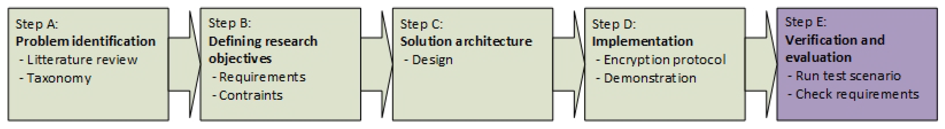
Under this scope, our security-related studies followed five consecutive steps (Figure 1), following the Design Science Research Methodology (DSRM) defined by Peffers et al. [5]. Initially (A), the operational constraints and the NFV forwarding standards were surveyed [6]. Consequently (B), the security requirements have been identified aiming to accommodate the requirements extracted from the aforementioned studies [4]. Thirdly (C), an automated forwarding architecture has been developed based on a web service architecture, aiming to accommodate the requirements and the constraints [3]. The fourth step (D) in our studies was to develop a security protocol for exchanging encryption keys between SFs [7]. This article (E) integrates the previous results into a customised NFV environment and combines it with SFC routing [8]. In order to overcome the network constraints, we developed a customised virtual switch by the use of P4 [9] in order to support a new SFC packet header based on Network Service Headers (NSH). Accordingly, we aim to verify that this implementation fulfils the requirements we have developed in our previous work.
Section 2 summarises the related work to this research. Section 3 presents the operational context under which the developed architecture was designed. Section 4 and Section 5 present the architecture and implementation, while Section 6 gives a verification of the presented scenarios for a closing demonstration. Through defining three episodes in this scenario, we seek to highlight how the elements presented in this paper are supporting a secure SFC implementation in NFV.

2. Related Work

In recent years, NFV based solutions have become a very active research area, due to the benefits promised by cost-effective solutions when virtualising network equipment. Within the research area of NFV, SFC forwarding protocols and their corresponding control plane mechanisms are NFV research areas that have gained attention [10,11,12]. Nevertheless, the security research on these networking standards is limited, where none of the SFC standards are protecting the privacy and the integrity the data plane traffic [13]. This is a complex problem that consists of data protection problems on multiple levels; the orchestration plane, the control plane and the data plane. Hence, our work aims to cover this research gap, by providing a new packet forwarding standard that is reflected on all these planes.
From a data plane perspective, the Internet Engineering Task Force (IETF) workgroup NVO3 [14] have considered multiple overlay protocol for use in data centres. Generic UDP Encapsulation [15], Geneve [14], VXLAN-GPE [16], and NSH [17] are all protocol competing to be the next standard. They all have limitations related to multi-vendor and multi-domain interoperability and they also have a lack of security extensions. MPLS-SR [18] does support multi-domain topologies, but, in an SFC context, they all rely on the underlying protocol, such as IPSec tunnels, to provide encryption. However, such a tunnel can be perceived as a wire between data centres. Multiples of these tunnels constitute a virtual overlay network that is unprotected from all data threats that reside within the network. Then, there is no protection of the integrity of the headers of the data-flow across multiple domains. In IPv6, Segment Routing (SR) [8] is supported; however, during encryption, the header is replaced and the segments become invisible for intermediate routers. We aim to solve this by introducing a new overlay packet header that supports encryption inside the overlying network protocols, such as NSH.
With respect to interconnected control planes, we have earlier showed [6] that there are two orchestration methods across multiple service provider domains. (1) A top-down approach by utilising a hierarchy of orchestration planes [19] or control planes [20] or (2) by using an east–west control plane approach such as SDNi [21] or BGP [22]. Both interconnection methods try to overcome the problem of multiple forwarding standards and multiple types of network controllers. The industry has responded by providing tenant-based data centres, where each tenant extends their data centre across multiple sites and omits the need for control plane interconnections. Networking by NSX-T [23] from VMWare is one example of such multi-tenant data centre technologies where a micro-segmented infrastructure can span over multiple sites. However, most of the underlying network protocols, such as Geneve [14] in NSX-T, are not capable of combining SR with micro-segmentation and flow-based encryption. Hence, we have in our previous work [3] suggested a new SFC header, based on an NSH extension that adds more granularity to the security aspect of an SFC. Correspondingly, we have in this paper developed a RESTconf based control plane for distributing the forwarding decisions of this new packet header.
Introducing a new packet header has historically been problematic with respect to the adoption into existing hardware. When a new network protocol was suggested, the network operators had to wait for a set of standardisation documents from organisations such as IETF and ONF [24]. Furthermore, they also had to wait for the switch vendors to develop a new software version. Sometimes, a new network standard also required new hardware. The Programming Protocol-independent Packet Processors (P4) [25] language aims to solve this issue by defining a framework that directly programs packet parsing and packet forwarding instructions to a switch in runtime. Then, network operators themselves can program their switches and add new protocols and features to them. The ONF group is currently aiming for standardising P4 as a part of SDN through the Stratum project [24]. In this research, we run P4 inside a Virtual Machine in order to simulate a virtual switch. Due to the lack of OpenFlow implementations in our P4 framework, we used RESTconf for the control plane protocol.
From the encryption perspective, no protocols have been found for providing micro-segmented and flow-based encryption per SFC. However, our previous work [7] that originated from Software-Defined IPsec Flow Protection in SDN [26] and IPsec Key Exchange using a Controller [27], showed how encryption and Software-Defined Security Associations (SD-SA) could be adapted to an NFV domain.
In this paper, we combine this SD-SA encryption architecture [7] with our new SFC header [3] and a new flow distribution control plane. The security features of the architecture are verified by demonstrating how the requirements such as isolation and encryption comply with a use case scenario.

3. Operational Context of Proof-of-Concept Scenarios

This section presents a use case scenario of SFC isolation and encryption. Furthermore, we show three episodes of this scenario that are developed based on a set of architectural security requirements.

3.1. Use Case

The verification scenario for our Proof-of-Concept demonstration is based on a fictional Internet Service Provider (ISP) that wants to extend their NFV portfolio and their data centre resources. The ISP located in country A, named ISP-A, wants to lower their costs on their Customer Premise Equipment (CPEs) by virtualising them and consequently more efficiently extending their service delivery. They have limited resources in their data centre and want to offload parts of their services to remote data centres. They have found two cooperative partners in country B (ISP-B) and country C (ISP-C) that can provide them with data centre resources. They want all data centres to contribute to delivering and extending their virtual CPE (vCPE) services. They are aiming to provide this by chaining SFs across all data centres by the use of the SFC protocol NSH.
The IETF has defined a variety of SFC use cases [
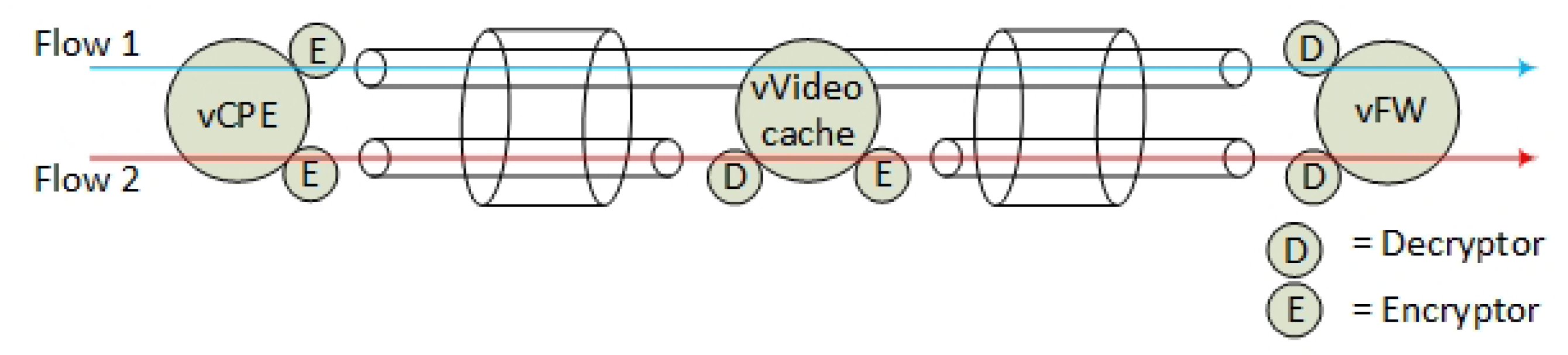
28], but, for our Proof-of-Concept demonstration, we limit the SFC use case to the following: ISP-A aims to provide three SFs to their customers. Two of the SFs are mandatory, while one additional SF is optional for the end-users to choose. The basic SFs are a vCPE (SF-1) and a firewall (SF-3), while the optional SF is a video caching service (SF-2). Due to the cost of data centre resource consumption and SF security policies, the ISP-A policy is defined to require that the vCPE runs at ISP-A, the video caching service at ISP-B and the firewall at ISP-C. The vCPE is the first element in the SFC. The additional video caching service is placed in the middle of the SFC in order to let the first two services be protected by the last element in the SFC, which is a virtual firewall (SF-3) (Figure 2). Hence, from a service plane perspective, the firewall is protecting the inner SFs and the end-user from the outside world.
The data centres operate with multi-tenants where ISP-A has interconnected all their tenant instances in an overlay network. In this setup, ISP-A is concerned about the privacy of their customers and they do not know if ISP-B is eavesdropping the end-user traffic traversing them. Neither are they sure whether ISP-B is malicious. ISP-C is, on the other hand, a trusted partner. In order not to let ISP-B being capable of eavesdropping all end-user traffic, all traffic that is traversing ISP-B, except video streaming traffic, must be encrypted. Note: for Proof-of-Concept purposes, the video caching service is categorised as a non-privacy sensitive service.
We simplified the SFC isolation problem by omitting a full mesh topology of the interconnected data centres in the Proof-of-Concept scenario. However, the components in a full mesh topology are also vulnerable to eavesdropping. Corrupt intermediate virtual switches or faulty SFs can modify, intercept and manipulate SFC traffic inside an overlay network. Hence, the protection of the Virtual Link (VL) [2] is relevant both between the Compute Nodes in one data centre and for the VLs between multiple data centres.

3.2. Requirements

We have in our previous work presented the NFV security requirements [4] for the encryption and the isolation of the VLs. We summarise these requirements in the context of the aforementioned scenario:
  • Hop by hop encryption—In order to prevent eavesdropping of the VLs, the VLs must be encrypted per SFC.
  • Micro-segmented isolation—The SFC specification [2] does not allow micro-segmentation within one SFC. However, we state that the end-user requires that they must be able to specify what data traffic the SFs are allowed to handle on a flow-based level. Hence, it is required that the associated data plane components are capable of isolating different packet flows with different encryption keys within one single SFC.
  • Header visibility—When encrypting VLs, the SFC packet header must be non-encrypted in order to enable SFC routing of the encrypted packets. We define that a new SFC header extension must be able to both allow and specify when the inner data-content of an SFC packet header is encrypted.
  • Control plane flow distribution—Multiple encryption-flows within one SFC require that the control plane is capable of distributing route information about each of these encrypted flows. These flow-rules must be securely distributed. Hence, secure and trusted intra- and inter-domain communication channels from the virtual network devices to the network controllers must be established.
  • Key distribution—Due to a non-bidirectional data plane between the SFs in an SFC [2], a new hop-by-hop key distribution mechanism is required. The key distribution mechanism must respond to a dynamic SFC behaviour such as an SFC modification. It must also support future encryption standards or protocol extensions. The key distribution mechanism must ensure confidentiality, integrity and availability of the keys.
  • Compliance and adoption—A new SFC header and the corresponding provisioning architecture must be compliant with the current NFV standards. In addition, adding encryption to the VLs should not degrade the end-to-end throughput performance more than traditional end-to-end encrypted channels. Another important factor for the architecture to be adopted is that the end-users do not perceive a significant increase in service provisioning times when they apply VL encryption.
  • Resilience and availability—The architecture must provide resilience towards components failing without reducing the level of security.
  • Security integrity—An attacker should not be able to manipulate the routing tables or to modify the packet headers in order to enforce access to non-encrypted data packets.
We aggregated these requirements and defined the following episodes from the aforementioned scenario.
Episode 1: Packet forwarding and provisioning (Req: i, iii, iv, vi)
This episode is created from an end-user perspective. An end-user orders a new virtual service according to our scenario. The end-user expects that his broadband service is not affected during service provisioning. A service provisioning demonstration can monitor the provisioning time by measuring network outage. However, demonstrating a full service provisioning also provides evidence of how the architecture provides the setup of the encrypted VLs. In addition, in a fully provisioned SFC, an end-to-end traffic test shows how the encrypted data packets are routed and if the traffic flow is satisfying the security requirement of flow-distribution.
Episode 2: Resilience and availability (Req: v, vii)
In this episode, we simulate hardware failure. From an availability and resilience perspective, the architecture must be resilient to components failing without compromising the network encryption policy. During service recovery, this demonstration also shows the dynamic behaviour of the key distribution during failovers.
Episode 3: Security integrity (Req: ii, viii)
For our third episode, we simulate that one of our data centres (ISP-B) is attacked and that a subset of the components is compromised. When simulating a set of basic network attacks, the architecture must be resistant to this. This also includes a demonstration of how flow-based encryption can protect the end-user data from being compromised by a malicious ISP (ISP-B).
Aiming to highlight a selected subset of the functionalities supported by our developed security architecture, we next present the architecture and the implementation of our Proof-of-Concept demonstration. Section 6 evaluates how the following architecture fulfils these episodes.

4. Encrypted SFC Architecture

In this section, we describe the architectural components and the network topology for enabling encrypted and isolated VLs. This work follows the design guidelines from our previous work [
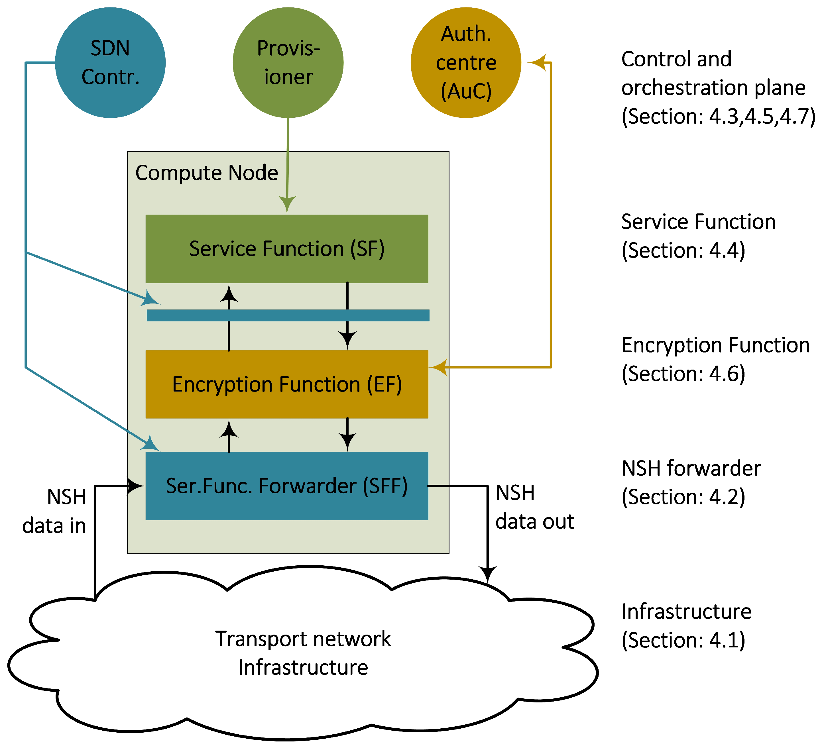
3] where we presented an architecture consisting of a tiered structure of data plane and control plane components. This architectural section summarises this work and focuses on the implementation-specific elements of the design. The main objective of the design is to structure a layered networking architecture into a data centre environment. Specifically, this includes a design of interconnected Compute Node components that are capable of forwarding encrypted SFC packets by the use of two layers of NSH headers. Accordingly, we have provided three data plane components running on the Compute Nodes (Figure 3); a new Service Function Forwarder (SFF), a new Encryption Function (EF) and a new forwarding framework for the Service Functions (SF). These components are based on the programmable switch language P4 [9]. Figure 3 shows that these data plane components also have their corresponding control plane units, following the Software-Defined Networking paradigm of centralised control and network programmability. We used a micro-service design principle and implemented each of these components as Virtual Machines (VMs). According to our previous work [3], we used RESTConf web services to exchange messages between these components.
The following subsections discuss the functionalities of these data plane components (Section 4.2, Section 4.4 and Section 4.6), the infrastructure that they are connected to (Section 4.1) and the control plane units they interact with (Section 4.3, Section 4.5 and Section 4.7).

4.1. The Infrastructure

The nature of an SFC accommodates Segment Routing (SR) [18,29,30], which implies that the sender of an IP packet specifies the packet path. Specifically, SR implies that the packet header contains SFC state information of how to route a specific packet for a selection of intermediate routers. We use NSH as a data plane enabler for SR in order to steer the traffic in such SR paths between the SFs and the EFs (
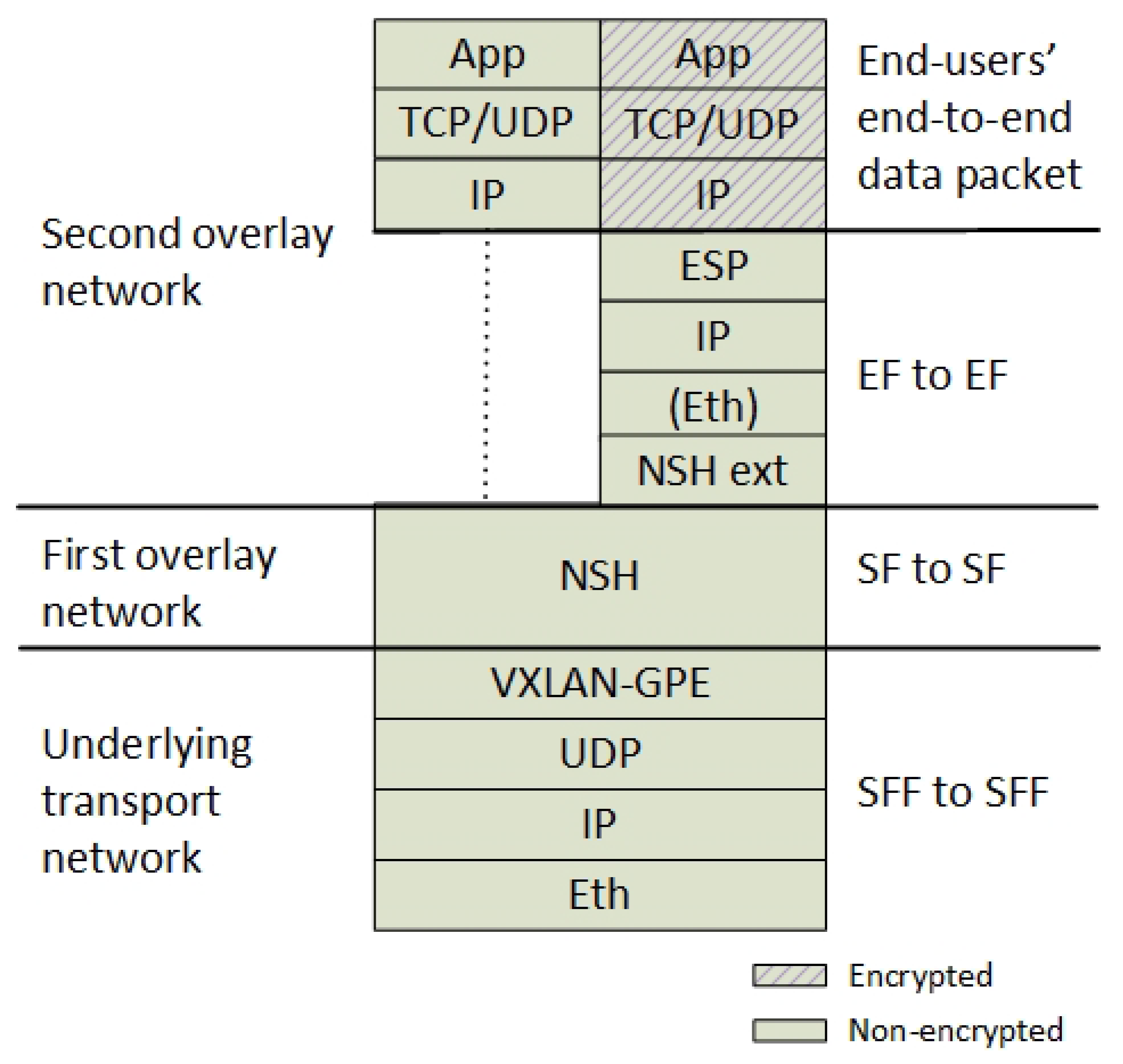
Section 4.1.1). Two layers of NSH headers constitute two overlay networks. One layer addressing the communication between the SFs and one additional layer addressing the point to point communication between the EFs (Figure 4).
Currently, SR by NSH is not widely supported by routers and neither is the new NSH encryption header extension that we have suggested. Therefore, in order to ensure packet forwarding through legacy network devices, we define that the NSH packet must be encapsulated by an outer transport network between the NSH-aware routers. Figure 4 shows that we use VXLAN-GPE for this underlying network. Each of these network layers accommodates the different communication layers in the architecture. For example, an NSH header is only valid between two SFs, while the new additional NSH header is only valid between two EFs. Hence, the structured packet header (Figure 4) is also reflected in a structured design of the networking components (Figure 3), where each data plane component is responsible for each layer.

4.1.1. Overlay Network Topologies

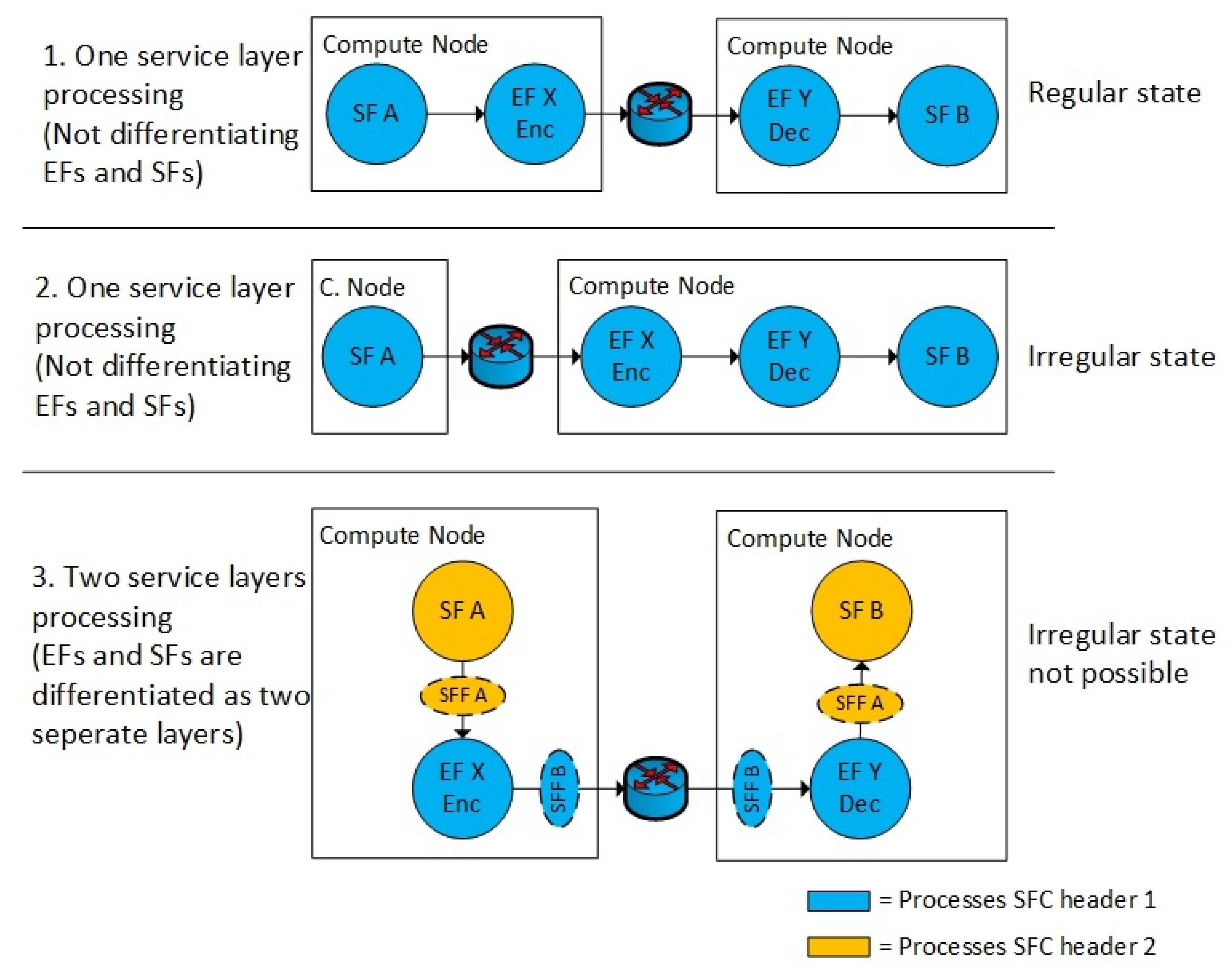
This structured setup of the networking components ensures that the routing of the data packets is not only controlled by flow-rules, but it is also controlled by how the network topology is designed. This is the main objective behind the design of the structured hierarchy of the NSH headers. The structured network topology disallows unencrypted data traffic between an SF and an EF to be routed out of the Compute Node and out on the network.
Figure 5 shows the main difference between using and not using an additional NSH header. Within the current NSH RFC [17] (no additional NSH header), the EF must be treated as a regular SF on one NSH layer (Figure 5 (1, 2)). The VL is perceived as encrypted and protected if both the EF and SF is located on the same Compute Node. However, if the EF is migrated to another host (Figure 5 (2)), the non-encrypted traffic (between SF-A and EF-X) is in fact allowed to flow both between different Compute Nodes or between different infrastructure domains. Hence, enabling the EF in a separate network layer (Figure 5 (3)) makes the network topology more secure. Using two NSH layers ensures that the SF never can be distributed in a way where non-encrypted traffic can leave the Compute Node. The VM, such as the EF-X (Figure 5 (3)), is in this case also open for VM migration, but, if the VM EF-X is migrated to another Compute Node, the next-hop network destination is unavailable due to a header mismatch between the two types of NSH headers. Hence, the VM’s EF-X and SF-A must be migrated in pairs for allowing the communication between them.
Dedicated networking components per Compute Node that are responsible for the inner and the outer NSH headers logically separate the EFs and the SFs. Therefore, we implemented two separate virtual switches on each compute node that is responsible for the routing of the two NSH layers. This structured setup of Compute Node components (Figure 3) ensures that the EFs must be co-located with the SF.

4.1.2. Underlay Network

A threat to this structured networking model is an underlying VXLAN-GPE network. In traditional data centres with no NSH overlay, VXLAN is not defined as an underlay network, but it constitutes an overlay network by abstracting the physical network into one big distributed virtualised switch. This implies that, if all the components in our architecture are running as VMs on one underlying distributed virtual switch, the overlaying NSH switches are unaware of the underlying Compute Node location. This compromises the structured setup of networking components on the Compute Node. We solved this problem by combining VXLAN and NSH networks into one customised virtual switch. In addition, we adopted the architectural networking principles from VMware NSX [23] and pinned the virtual switch to the Compute Node and perceived it as a hypervisor component. We simulated this structure by locking the virtual switch VM to the Compute Node and pretending that the virtual switch was not available in the hypervisor user space. According to the SFC RFC [2], introducing NSH/SFC-awareness to a virtual switch makes it a Service Function Forwarder (SFF). Hence, we defined two underlying SFFs to be responsible for each NSH layer respectively and let them also to be responsible for handling the VXLAN-GPE tunnels.

4.2. The Service Function Forwarders

In order to support the new NSH packet header formats [3], we created a new customised virtual switch, based on P4. The programming language P4 enables programmers to customise packet forwarding rules in switches. We made a very simple switch that constitutes an SFF, with VXLAN-GPE and NSH forwarding support. The SFF has the following functionality:
  • It can parse the new encryption attributes in the NSH header (MD-type = 3, E-SPI, E-SI [3]).
  • It classifies IPv4 traffic in order to apply NSH headers.
  • The SFF can act as a forwarder for NSH packet destined to other SFFs.
  • It can act as an NSH packet forwarder inside an SF in order to make the SF NSH-aware.
  • It can provide Layer 2 mac-address resolution based NSH packets instead of using IP and ARP (see Section 4.4).
  • It can provide VXLAN-GPE support.

4.3. The Service Function Forwarder Controller

In our previous work [3], we have suggested using BGP as a control plane mechanism in order to have a standardised method of exchanging NSH routes. However, we identified concerns related to scalability and security of using BGP. Applying route security in BGP includes that each route has to be authorised on a per-peer basis and all viable routes need to be pre-enumerated. In addition, with no route aggregation, route propagation and exponential growth of BGP routes for EFs, we question the scalability of BGP as an NSH control plane protocol. Hence, we changed the control plane component from our previous work [3] from BGP to distributed RESTconf. This opened up for more efficiently giving the exact routing instructions to the specific Compute Nodes only. RESTconf also enabled a more flexible authorisation of the NSH routes, by authenticating the RESTconf connection by the Secure Socket Layer (SSL).
However, we also selected RESTconf as the control plane protocol due to interoperability reasons. In federated multi-tenant NFV environments, an overlay network is created with virtual forwarding devices such as an SFF. This opens up for customising the virtual network devices and the network controller. This enables network operators to deploy customised networking software in an agile and fast manner. By utilising P4, it is also possible to specify customised flow rules when configuring these network devices. Hence, we utilised the feature of SDN-based network programmability, by specifying customised network configuration by the use of P4 flow rules over RESTconf. The need for customised flow rules is reasoned by the new NSH header extension.
For Proof-of-Concept purposes, we created a very simple RESTconf based network controller with a set of predefined P4 flow-entries. It consists of a simple HTTP client that distributes flow rules over RESTconf by using Linux shell scripts.

4.4. Service Functions

The Service Functions (SFs), applied as VMs, are intended to manipulate the end-user data packets. We simulated that we used SFs acting as a vCPE, video caching service and a virtual firewall by using dummy services. Therefore, all SFs are configured to simply forward all data traffic according to the flow-specification rules we apply. The SFC RFC 7665 [2] defines that an SF has primarily two data plane interfaces: one for incoming and one for outgoing traffic. Inside the SF, the packet forwarding is explicitly set to follow the SFC directions and not the standard routing table. Specifically, data traffic coming in on one interface must go out on the other interface and vice versa. We solved this SF routing problem by making the SF NSH-aware. This implies that the NSH header is not removed when a packet enters an SF. Due to the lack of NSH state capabilities in operating systems such as native Linux systems, we introduce a new virtual NSH network stack inside the SF. This new network stack is an NSH-aware P4 switch which acts as a front-end network stack inside the SF. This principle of NSH-awareness in the SF is extracted from the VXLAN-tool [31] implementation and adopted to a P4 environment in order to support the new NSH header. We defined the following features in the SF:
  • One SF can appear multiple times in one single SFC. Hence, the SF is NSH-aware by using an underlying P4 switch in the SF. The P4 switch is connected to two virtual veth interfaces facing the SF application and two native interfaces facing network interfaces of the VM.
  • According to the SFC specification, the SF should be independent of the IP subnet topology between the SFs. This means that the IP subnets connected to VM interfaces do not follow standard IP subnetting topologies. For example, when an SFC changes, the mac-address of the next-hop SF are also changing. From an SF perspective, this mac-address has to correspond to the next NSH hop. Hence, the virtual P4 switch in the SF must be able to map interface mac-addresses to SFs. For outgoing traffic from an SF, we use dummy static destination mac-addresses. For incoming traffic to an SF, it is the responsibility of the P4 switch to set the correct destination mac-address to the IP interface of the SF. This mac-address is based on next hop in the SFC. Hence, instead of using standard ARP as a binding between layer 2 and layer 3, we introduce a new mac-address mapping scheme between mac-addresses and NSH Service Function Identifiers. This is implemented as P4 flow-rule actions. A dynamic side effect of this is that the IPv4 addresses of the SF application theoretically can be reused for each hop in an SFC.

4.5. Service Function Provisioner

The Service Function Provisioner component corresponds to the Virtual Infrastructure Manager (VIM) in the NFV reference model [32]. It is responsible for maintaining the lifecycle management of all virtual network functions. We simplified this function and used Vagrant [33] and Vagrant scripts as a provisioning tool for all VMs per Compute Node. As an overlay to multiple Vagrant nodes, we used RESTconf to instantiate the Vagrant scrips.

4.6. The Encryption Service Function

This component is responsible for both encrypting and decrypting the data traffic in front of the SF. This functionality is realised with a data encryption application in a customised SF that we named the Encryption Service Function (EF). From a network infrastructure perspective, the EF is a copy of the SF, except for being responsible for a different network layer (the additional NSH layer). In addition to the P4 networking functionalities, the EF adopts the Software-Defined IPsec application (SD-SA) functionality that we have presented in our previous work [7]. In summary, this application has the following features:
  • We use the Linux based IP XFRM application to encrypt and decrypt IP packets and encapsulates them with an IPsec Encapsulating Security Payload (ESP) header.
  • The encryption application runs inside a Linux network namespace (netns) that separates the encryption application from the P4 switch.
  • IPsec Internet Key Exchange (IKE) is replaced with a new web service application that exchanges the encryption keys and the integrity keys in a separate control plane channel.
  • The EF is instantiated with a set of preshared keys. These keys are used to establish a secure connection to a centralised Authentication Center (AuC) that manages the key distribution.

4.7. The Authentication Centre (AuC)

The EFs are controlled by an Authentication centre that distributes the encryption keys and the integrity keys. Due to the non-bidirectional NSH communication channel between EFs [2], an IPsec IKE channel is not possible to establish on the data plane. Hence, we adopt the aforementioned SD-SA application from our previous work [7] in order to replace IKE in IPsec. In summary, this application includes the following functionality. The initial step is to pre-configure an authentication key for every EF during EF instantiation. Second, all EFs establish a secure channel to the AuC. Third, the AuC sends the integrity and confidentiality key to the encryption function over the authenticated and secured RESTconf channel. This last step is a periodic event that is repeated for every key change. An important requirement for this concept to work is that all EFs are connected to one common AuC. This also requires a shared control plane VPN between all data centre tenants. This control plane VPN is established by using site-to-site IPsec VPN tunnels between the data centres.

5. Implementation

Based on the aforementioned scenarios (
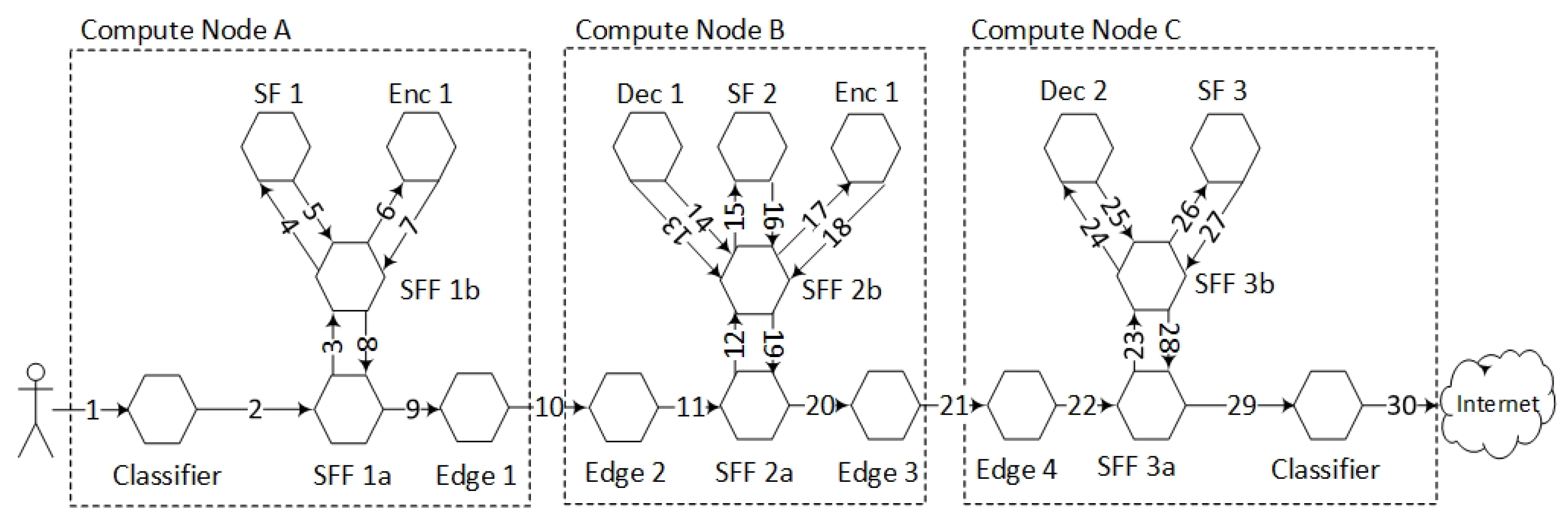
Section 3), we constructed a network topology consisting of three simple SFs and two underlying pairs of encrypted channels. Figure 6 shows the components that are involved in the data plane forwarding of the NSH packets.
This network topology setup implements the use case scenario (Figure 2) and also reflects the tiered network topology (Figure 3). We implemented this topology by running one Compute Node per ISP where each Compute Node had one inner and one outer SFF. We also configured an Edge gateway per network domain that was responsible for interconnecting the data centre domains. We used one Compute Node per NFV domain. Correspondingly, there is one Edge gateway per Compute Node.
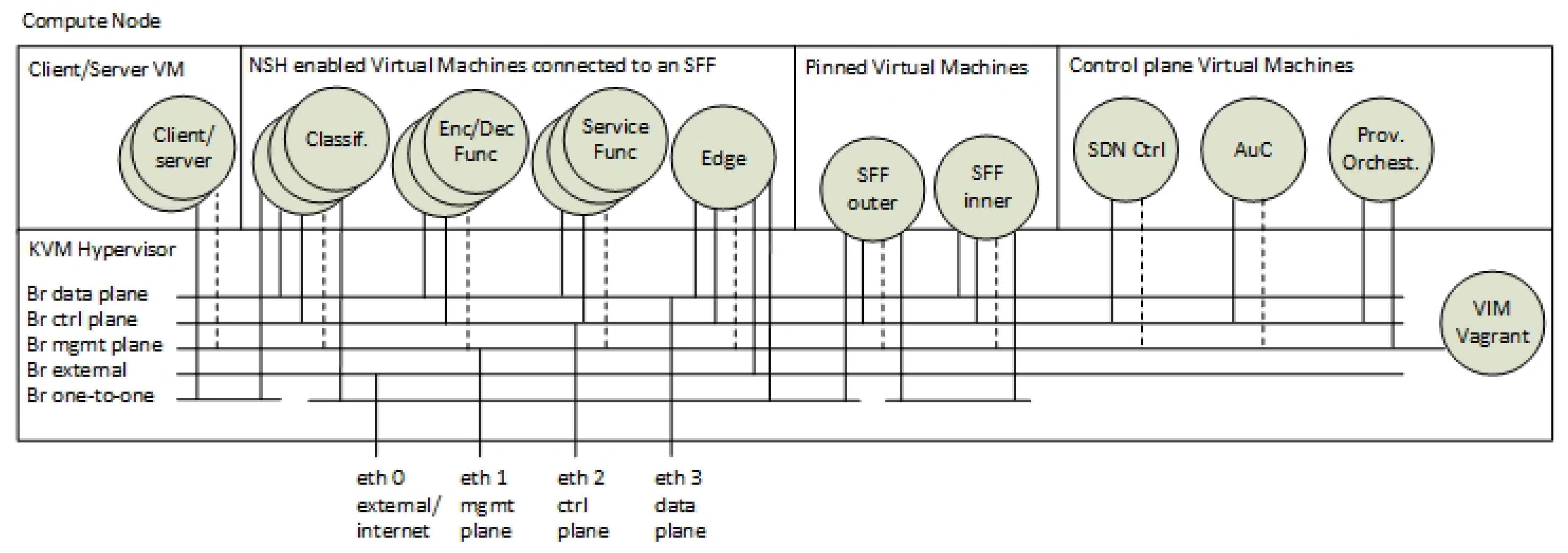
Figure 7 shows the categorisation, the enumerations and the virtual bridge connections of the VMs running on each Compute Node. The SFs, the EFs and the classifiers are instantiated as multiple instances of VMs. These VMs are instantiated per SFC during service provisioning. The SFFs are statically deployed VMs that are pinned to the hypervisor. The control plane components are also categorised as a special group of VMs. This is because they are only instantiated at one of the Compute Nodes and because they are not connected to the data plane.
From a networking perspective, Figure 7 also shows that each VM is connected to different Linux-bridge domains. We used virtual Linux interfaces (veth) to interconnect VMs to virtual bridges. Furthermore, these virtual bridges are also connected to the physical network interfaces. This network construction follows the principle of virtual network infrastructures in Linux that is also used in, for example, OPNFV [34] and OpenStack [35].
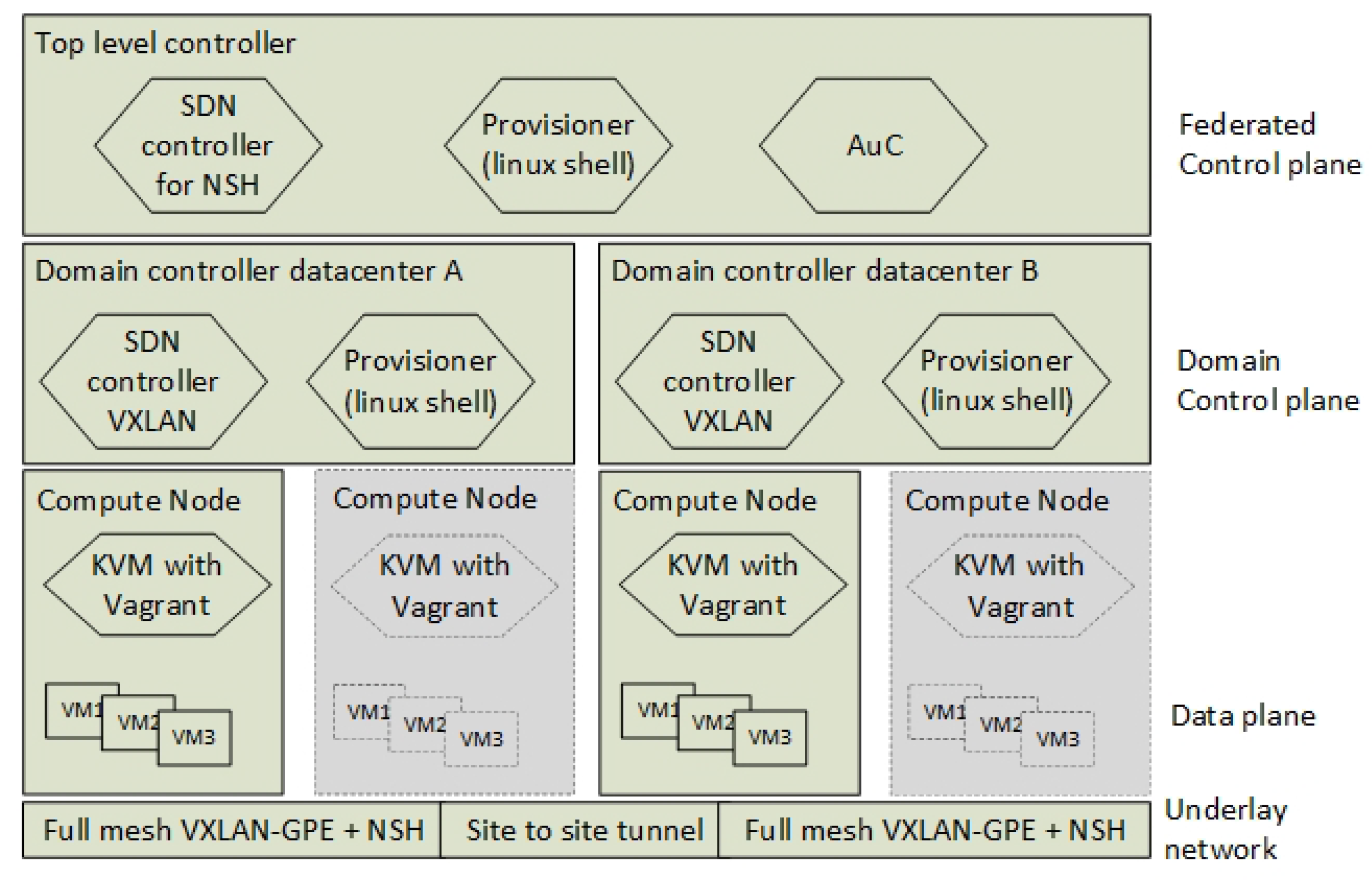
For local Virtual Infrastructure Management (VIM), we ran the VM provisioning tools and the local network/bridge management as non-virtual function alongside the Kernel-based Virtual Machine (KVM) environment. We used Linux scripts and Vagrant to control the instantiation of VMs and to control the mapping the virtual network interfaces to the underlying VXLAN-GPE infrastructure. The local VIM is orchestrated by a simple top-level RESTconf based orchestrator. Figure 8 shows the hierarchy of both this orchestrator and the other control plane components. For proof-of-concept purposes, we only used one Compute Node per domain controller.
The NFV implementation is developed by the use of Vagrant, Linux bash scripting and the switch programming language P4. The source code, the demonstrations and the test results are available at https://github.com/gunleifsen/encNSHinP4.

Lab Setup and Tools

We set up our experiment by using four HP Proliant DL380 G7 servers. All servers had two 3.47 GHz Intel Xeon X5690 processors with six cores each, 196 GB of DDR3 memory and 1 Gbit network adaptors (In a testbed provided by Eidsiva broadband, Oslo, Norway). The servers ran Ubuntu 18.04.2 LTS with kernel 4.15.0-47-generic. We used Vagrant 2.2.4 and qemu-kvm 1:2.11 with virtual network adapters by libvirt. For every Compute Node, we disabled Hyper-Threading, Turbo Boost, and power saving.
We simplified the instantiation of the VMs by only using one VM template for every VM. This VM template was set up with Ubuntu Linux 18.04.2 LTS, 2 GB RAM and one virtual CPU. The pre-installation of the template included the P4 framework (https://github.com/jafingerhut/p4-guide) where we used the P4 version P4_16 with the behavioural model 2 (BMv2) from Barefoot [36]. For running the P4 code, we used the inner virtualisation software from Barefoot named the “simple_switch”.
For all communication between the VMs, we simulated RESTconf by the use of simple web services running over secure netcat (socat) [37].
According to the scenario and the service plane topology, we created 21 VMs for data plane forwarding, including two endpoints (Figure 6). In addition, for the federated top-level controller, we combined the network controller, the service provisioner and the AuC in one common VM (22 VMs in total).
For end-to-end traffic testing, we used Iperf 3.0.11 for measuring the performance and provisioning time. By sending a fixed stream of packets per seconds, we measured the network outage time by counting the packet loss. For packet injection tests, we used the Python tool scapy [38] and, for packet monitoring, we used Tcpdump on the virtual Compute Node interfaces (veth).

6. Verification and Results

This section presents the results of the three verification episodes we introduced in Section 3. This includes (1) a packet forwarding and provisioning episode, (2) a resilience and availability episode and (3) a security integrity episode.

6.1. Episode 1: Packet Forwarding and Provisioning (req: i, iii, iv, vi)

This episode aims to provide a demonstration of the service provisioning. It also aims to show that the data packets are routed correctly and that end-to-end traffic tests and throughput tests are satisfying the requirements.

6.1.1. Service Provisioning Times

From an end-user perspective, it is expected that their NFV ISP provides them with on-demand service provisioning and a secure infrastructure. We developed episode 1 in order to provide a Proof-of-Concept demonstration of the implemented architecture with respect to service provisioning. This demonstration also shows that the layered NSH header architecture is capable of forwarding encrypted SFCs according to a network forwarding policy in a relatively fast and reliable manner. Specifically, we developed a test that demonstrates that the designed architecture is able to set up an SFC according to the requirement of hop-by-hop encryption with a new NSH header (req: i, iii) and by the use of RESTconf flow distribution (req: iv). We provide these demonstrations by monitoring the provisioning time of a subset of the services in the architecture.
The creation of VMs, the altering of the routing paths and the reestablishment of the encryption keys, result in network outage from an end-user perspective. Hence, we measured this time by monitoring network outage during service provisioning. We set up a simple Iperf measuring test between the client and server and experimented with altering the SFC. We altered the SFC from SF1 > SF3 to SF1 > SF2 > SF3. This simulated turning on and off the SF located at ISP-B and implicitly adding and removing a service from the SFC.
By sending a fixed stream of 64 packets per seconds from the client to the server, we measured the network provisioning time by monitoring the packet loss during these service alternations. One packet loss of 64 packets corresponds to approximately 15,63 ms of a network outage. The measurements were aiming to measure seconds. Therefore, we set the packet rate at 64 pps. This also ensured a minimisation of a potential packet loss due to unrelated reasons such as collisions, traffic congestion or buffers overflows.
We differentiated the measurements (Table 1) in three types. Full provisioning (1a) with no traffic flow during provisioning, Soft provisioning (1b) where the data traffic runs while new services are instantiating and (1c) we also measured the periodic key change provisioning times.
Setting up an additional SF with encrypted links includes; (1.a-1) instantiating the SF VM, (1.a-2) instantiating two EF VMs, (1.a-3) authenticating the EFs and distribute the encryption keys and (1.a-4) distribute the new flow routes. Hence, we measured the provisioning time for each of the sub-processes and summarized the total provisioning time (1.a).
The instantiation of the SFs (1.a-1) and the EFs (1.a-2) are the most time-consuming processes. However, these processes can be instantiated before the traffic flows are redirected into the new VMs. This also includes the setup and authentication of the EFs (1.a-3). We refer to this process as soft provisioning (1.b). It is expected that such a planned provisioning is most common. Here, the distribution of the flow rules is not assigned before the VMs are fully provisioned and EFs are authenticated. This scheduling of network provisioning significantly decreases the network outage time. However, for non-controlled events, such as hardware failure, the re-provisioning time increases due to the failure detection time and due to the lack of pre-instantiated VMs (see Section 6.2).
The periodic key change provisioning time is the most frequent provisioning process. It is assumed that the encryption keys are set up to change once every hour. However, for measurement purposes, we set the periodic key change interval to 5 s. Our previous work [7] indicated that the periodic key change provisioning had limited effects on the network outage time. This is also confirmed by these measurements where the network outage time for each key change is about 0.1 s (1c).
From an end-user’s perspective, the most relevant network outage times are the outages during the soft provisioning and during periodic key changes. It is expected that most web applications based on TCP, such as Youtube and Netflix, are resistant to these network outage times that are less than 100 ms. Re-using an EF in order to reconnect it to a different EF peer has a provisioning time of 1.2 s (1.b-1). Hence, this result indicates that it is more efficient to pre-instantiate and pre-authenticate a new pair of EFs instead of reusing any existing EFs during re-provisioning. This pre-authentication consequently sets the soft provisioning time and the network outage time to only include the time it takes to distribute the flow rules. It is assumed that the network outage time caused by the re-distribution of the flow rules is not perceived as network outage by most end-users.

6.1.2. Throughput

According to the requirement of adoption (req: vi), we argue that the architecture fulfils this requirement by using fully virtualised overlay networks. The new NSH header only needs to be implemented in virtualised environments and therefore it is also easily deployed in fully isolated, autonomous and customer-specific environments. However, other important factors for adopting the architecture are scalability and throughput performance. The TCP throughput is a product of bit rate, packet-size and latency. Hence, the latency factor for throughput performance is highly dependent on the number of NSH forwarders, their latency in processing packets and the latency between them. Hence, we measured the throughput by varying the number of SF and EF hops (Figure 9). We tested the throughput from the client to the server by using an Iperf TCP bandwidth test with window-size 512.
The results (Figure 9) show a decreasing throughput when the number of SF hops increases. The main reason behind this result is the increased latency that the virtual machines introduce. We measured that a VM with a P4 enabled switch in average used 6 ms to process a packet. The virtualisation software we used for P4 is based on CPU processing without any network accelerator driver. This lack of suitable software drivers for P4 explains this latency. However, it is expected that new generations of OVS, IPAC and other P4 runtime environments will decrease the packet processing latency in future releases of the P4 runtime frameworks.
However, the most important factor with respect to NFV adoptability (req: vi) is how much degradation in throughput the encrypted links introduce. Hence, we measured the difference between EF and SF hops, by creating multiple SFCs with and without encrypted Virtual Links. The graphs (Figure 9) show that there is no significant difference in the throughput between an SFC with EFs only and an SFC with SFs only. This confirms that it is the P4 switch that introduces the latency and that the performance degradation is due to the P4 hypervisor or the effectiveness of the P4 program.

6.1.3. Summary

The overall results show that the solution is fulfilling the following requirements:
Req i ✓: We have shown that the architecture provides hop-by-hop encryption by monitoring the traffic flows before and after the provisioning of the EFs. In addition, small network outages during re-keying confirm that the encrypted links are running and that the key change is working.
Req iii ✓: The fact that requirement i is fulfilled also confirms that the forwarding of the new packet header is possible when the Virtual Links are encrypted. Hence, the new SFC header is not encrypted. This is also confirmed by analysing SFC packets.
Req iv ✓: By running provisioning and alternating different network topologies, we have shown that a RESTconf based control plane in a multi-tenant environment is capable of distributing micro-segmented flow rules according to the requirements.
Req vi ✗: By applying the NSH header in an interconnected multi-tenant data centre, we have shown that the new NSH header is easily adaptable (Section 4.1). This is because the NSH header is applied in an overlay network. Throughput tests have shown that a single EF does not degrade the throughput performance more than a single SF. However, due to the lack of an effective P4 virtualisation platform in our implementation, the performance significantly degrades when the number of SFs increase. Hence, the adoption of P4 in NFV is highly dependent on hardware accelerators.

6.2. Episode 2: Resilience and Availability (req: v, vii)

The capacity of the architecture to adapt to controlled network alterations has been demonstrated earlier with respect to the network provisioning. This episode has been developed in order to highlight the details of the process and to show how the architecture responds to software or hardware failures (req: vii). Hence, we simulated that the intermediate ISP-B has a hardware failure and becomes unavailable. In addition, we have also simulated the consequences of unavailable control plane components and tested protection mechanisms in the key distribution method (req: v).

6.2.1. SFC Protection

Our Proof-of-Concept implementation of the P4 data plane did not include any event handlers of detecting network failures such as link-down or node-down (such as LLDP discovery events in OpenFlow). However, we simulated an “NFVi fault and management” [1] approach similar to ceilometer monitoring in OpenStack, by monitoring the VMs instead of the virtual switch interfaces. Consequently, we assume that the NFV infrastructure is capable of automatically migrating the VMs to another Compute Node during hardware failures. However, this migration process results in network outage time for the end-user where network outage time = detection time + VM provisioning + key distribution + route distribution (Table 1 (2.b)). In order to reduce the network outage time, it is possible to pre-instantiate redundant VMs. Consequently, the VM provisioning time is removed from the equation. Hence, we simulated a protection of software and hardware failure by duplicating the VMs running at ISP-B to also run at ISP-A. By letting the VMs run in both domains, the VM becomes protected and, consequently, it also creates an SFC protection. In order to simulate a hardware failure, we manually shut down the VMs running at ISP-B by using KVM virsh directly on the VMs.
Table 1 (2.a, 2.b) shows the failover time when SFC protection is enabled and when it is not. A network topology with SFC protection enabled provides evidence for a resilient and dynamic SFC architecture (req: vii). However, it is noted that the SFC protection introduces an additional resource consumption for all the VMs that are running in standby mode.
A method of reducing the resource consumption is to reduce the number of duplicate EFs. The aforementioned demonstration duplicated four EFs. Consequently, the additional pairs of EFs were already authenticated and failover is performed by a distribution of the flow rules only. By not duplicating EF1 and EF4, these EFs can be reused in order to reconnect to the duplicated versions of EF2 and EF3. This adds an additional 1.2 s to failover process, but it reduces the overall resource consumption.

6.2.2. Protection of Invalid VM Migration

The main objective of the architecture is to enable hop-by-hop encryption of VLs (req: i). This includes protecting the data traffic between two SFs with a pair of EFs. Hence, one of the most important features of the architecture is to ensure that non-encrypted data between an SF and an EF reside on the same Compute Node. We demonstrated the feasibility of the hop-by-hop encryption during the provisioning in episode 1 by running end-to-end traffic tests. Here, we also verified that the traffic was encrypted by monitoring the data traffic in the SFFs.
However, with respect to resilience, the aforementioned episode did not consider the consequences of VM migration. A failover of the VMs implies that SFs and their connected EFs must be migrated all together. A misconfiguration or failure in the VM migrations can result in an irregular topology of SFs and EFs. Hence, we aim to verify that the layered network topology introduced in Section 4.1.1 is protecting the non-encrypted flows from entering the network. We configured an invalid network topology by migrating one of the EFs to another Compute Node as we showed in Figure 5 (2). In this case, our architecture and flow policy disallowed the distribution of the flow rules. This result was expected. However, we successfully managed to manually override and manipulate the flow rules in order to allow such traffic flows. In order to accomplish this, we had to (1) manipulate the NSH packet coming from the SF and (2) define a flow rule that sets the NSH next hop to be a remote SFF destination for an NSH packet that is tagged for going into an EF for encryption. This is a clear flow-rule policy violation. This policy violation is easy to detect because the SFFs are pinned to the Compute Node. Hence, an NSH packet that is heading to an encryption function should never leave the outer SFF.
The demonstration confirms that the tiered SFF infrastructure and the pinned SFFs make it easy to control the inner encryption flows. It also shows that there is a need for providing policy rules for the P4 switches. We enforced this rule only by implementing it in the overlay RESTconf API.

6.2.3. Key Distribution

Due to the lack of a direct data plane communication between two SFs, we developed a new key exchange mechanism by using centralised key distribution (req: v). Our previous work [7] has shown that SD-IKE with a centralised key distribution and Authentication centre (AuC) makes key distribution more efficient in non-NFV environments. The SFC alternations in episode 1 and the SFC failover protection in SFC episode 2 (Section 6.2.1) provides a Proof-of-Concept demonstration for integrating this concept in NFV.

6.2.4. Availability of Control Plane Components

The aforementioned key distribution is not only performed during provisioning, while the encryption keys change periodically. This makes the AuC service a critical component. Killing the AuC service does not affect the end-user traffic. It only stops the encryption keys from being renewed. Hence, an additional key monitoring agent must run along with the encryption and decryption services. This monitoring agent detects if a new key is not received within a certain expire time. If the expiry time is reached before a new key is received, the EF deletes its’ Security Association.
Instead of shutting down the AuC, we simulated this key protection feature by manipulating the key expire time in the encryption service. We experimented with setting the expire time to 10 s in the encryption service and the AuC re-keying time to 20 s. Next, we ran a simple Iperf bandwidth test for 60 s and used tcpdump to monitor if the packets traversed the intermediate SF. We confirmed the functionality by observing that the EFs periodically stopped working every for 10 s.
This declarative SDN approach for the AuC also applies to the network controller. When the SDN controller has distributed the flow rules to the SFFs, it is expected that the SFFs continue forwarding packets even after the SDN controller becomes unavailable. Consequently, network topology changes and VM migration together with a non-functional SDN controller results in non-functional SFCs. We confirmed this behaviour by shutting down the SDN controller.

6.2.5. Summary

This section has shown that the following requirements are satisfied:
Req vii ✓: First, the architecture opens up for enabling protection of EF and SF. The measurements of failover times provide evidence for a resilient architecture towards hardware or software failure. Second, we have shown that the layered network infrastructure provides resilience towards misconfiguration of VMs. Third, a security feature of protecting network security during AuC or network controller outage have been demonstrated.
Req v ✓: SFC alternation in Episode 1 and the protected failovers in Episode 2 provides evidence for an effective key distribution method in NFV environments.

6.3. Episode 3: Security Integrity (req: ii, viii)

For this episode, we simulated that the intermediate ISP (ISP-B) is compromised. The objective of the demonstration is to show that the integrity of the architecture is maintained for ISP-A and ISP-C even if ISP-B is compromised. We demonstrate this by showing that the architecture supports flow-based encryption (req: ii) and by showing that it is resistant to manipulation of the packet headers or flow injections (req: viii).

6.3.1. Eavesdropping

In order to demonstrate flow-based isolation and encryption (req: ii), we defined one SFC with multiple inner encrypted flows. The SFC is defined as SF1 > SF2 > SF3 where the flows are defined as email traffic and video traffic (over HTTP). SF1 is a vCPE that contains multiple network services. However, in this episode of the scenario, we define it to handle email traffic. Hence, SF1 is set up to handle all email traffic (port 25,110), while SF2 handles video traffic over HTTP (port 80,443). SF3 is a firewall that handles both flows. Due to the risk of eavesdropping, we encrypt the email traffic between SF1 and SF3 and we encrypt the HTTP traffic for SF1 > SF2 and SF2 > SF3.
We ran both traffic types simultaneously by running two instances of Iperf on two different ports, namely flow 1 (port 25) and flow 2 (port 80) (Figure 10). Hence, we classified the traffic into two different types, in total, three pairs of encrypted links. Flow 1 was defined as SF1 (vCPE) > EF1 > EF2 > SF3 (vFW). Flow 2 was defined as SF1 (vCPE) > EF3 > EF4 > SF2 (vVideo) > EF5 > EF6 > SF3 (vFW). By using tcpdump, we observed both encrypted and non-encrypted traffic flows at ISP-B. This confirmed that the architecture was supporting flow-based encryption.

6.3.2. Route and Packet Injection

The main focus of our contribution was to protect the SFC from being eavesdropped when the data traffic is traversing ISP-B. However, another attack method of gaining access to unauthorised traffic is to manipulate the packet forwarding services in order to redirect the traffic path and implicitly gain access to non-encrypted traffic. Hence, an important feature of the architecture is that it is resistant to packet injection or route injection (req: viii).
We did not find any method to inject flow rules into the P4 switch without compromising the network controller. However, for test purposes, we turned off the authentication and SSL on the RESTconf interface towards to P4 switch. This allowed us to manipulate the flow rules and consequently also manipulate the SFC.
For packet injection, we simulated that SF2 is compromised in ISP-B. We used an NSH extension in the Python based scapy tool [38] in order to inject packets into the data plane. We successfully managed to inject packets from an SF to another SF that was belonging to another SFC. Due to a lack of security features in the SFF, the SFF was not able to detect the VM source of the injected packets and simply forwarded the packet according to the packet headers. However, this was only possible for non-encrypted data flows.
This packet injection problem is similar to spoofing the source address field in IP packets. A possible solution to this problem is to introduce an integrity attribute in the NSH headers. Extending the NSH integrity header RFC [39] to support layered NSH can potentially ensure that the NSH packet originates from a valid VM source.

6.3.3. Summary

The verification of the security integrity objectives is summarised as follows:
Req ii ✓: We confirmed that the architecture supports flow-based encryption by observing encrypted and non-encrypted traffic traversing ISP-B. End-to-end traffic tests also confirmed that each flow was tagged with two different types of inner NSH encryption headers.
Req viii ✓: The architecture is resistant to simple packet injections and to the manipulation of flow rules. However, this packet integrity is established by using IPsec over the encrypted links. Hence, it requires that every Virtual Link is encrypted and that the Compute Nodes are not compromised. A possible solution in order to ensure packet integrity to non-encrypted data are to add an integrity key to the NSH header.

7. Conclusions

This paper proposes an architecture for on-demand provisioning of encrypted and isolated SFC using P4, NFV and SDN architectural principles.
A comprehensive view of the developed security framework for SFC has been presented, according to the scenarios executed during the concluding system validation demonstrations. A subset of the security-related functionalities supported by the developed architecture has also been shown in order to highlight critical architectural details towards its implementation.
Furthermore, this article unifies the publicly available results of our security-related studies, by highlighting how the distinct components presented earlier interoperate towards providing secure SFCs. The presented results highlight the capacity of micro-segmented SFC in NFV, given that the corresponding security requirements are satisfied.
The presented architecture is based on virtualised overlay networks and the upcoming technology P4. These technologies aim to overcome network protocol standardisation and interoperability issues. Hence, the architecture is applicable in any IP network and any Infrastructure as a Service (IaaS) platform. However, this abstraction of physical resources raises new standardisation issues within the virtualised environment, such as the encryption application in the service function. This puts a burden on the SF developers and calls for a standardisation of the encryption application interfaces in the SF and the AuC. Hence, this proof of concept experiment aims to contribute to the standardisation of NFV application interfaces for enabling encrypted Virtual Links.
Through the executed studies of encrypted SFCs, a variety of future work paths have been identified. These include the investigation of hardware accelerators, integrated QoS, availability and security policies, particularly for protected and encrypted SFC. Furthermore, another potentially critical path of future work refers to the investigation of packed injection between SFCs where encryption enabled SF is a possible solution.

Author Contributions

The main author of this paper is H.G.; V.G. and T.K. have contributed with respect to the paper structure, quality assurance and editing.

Funding

This research was funded by Eidsiva, the Norwegian Research Council and the Norwegian University of Science and Technology (NTNU).

Conflicts of Interest

The authors declare no conflict of interest.

References

  1. ETSI. Network Function Virtualization (NFV); Architectural Framework. ETSI GS NFV 001 v1.1.1. 2013. Available online: http://www.etsi.org/deliver/etsi_gs/NFV/001_099/002/01.01.01_60/gs_NFV002v010101p.pdf (accessed on 23 August 2019).
  2. Halpern, J.M.; Pignataro, C. Service Function Chaining (SFC) Architecture; RFC 7665; Internet Engineering Task Force (IETF): Fremont, CA, USA, 2015; Available online: https://tools.ietf.org/html/rfc7665 (accessed on 23 August 2019).
  3. Gunleifsen, H.; Gkioulos, V.; Kemmerich, T. A Tiered Control Plane Model for Service Function Chaining Isolation. Future Internet 2018, 10, 46. [Google Scholar] [CrossRef]
  4. Gunleifsen, H.; Kemmerich, T. Security requirements for service function chaining isolation and encryption. In Proceedings of the 2017 IEEE 17th International Conference on Communication Technology (ICCT), Chengdu, China, 27–30 October 2017; pp. 1360–1365. [Google Scholar]
  5. Peffers, K.; Tuunanen, T.; Rothenberger, M.A.; Chatterjee, S. A design science research methodology for information systems research. J. Manag. Inf. Syst. 2007, 24, 45–77. [Google Scholar] [CrossRef]
  6. Gunleifsen, H.; Kemmerich, T.; Petrovic, S. An End-to-End Security Model of Inter-Domain Communication in Network Function Virtualization. In Proceedings of the Norsk Informasjonssikkerhetskonferanse (NISK), Bergen, Norway, 25–31 August 2016; pp. 7–18. [Google Scholar]
  7. Gunleifsen, H.; Kemmerich, T.; Gkioulos, V. Dynamic setup of IPsec VPNs in service function chaining. Comput. Netw. 2019, 160, 77–91. [Google Scholar] [CrossRef]
  8. Filsfils, C.; Previdi, S.; Ginsberg, L.; Decraene, B.; Litkowski, S.; Shakir, R. Segment Routing Architecture; RFC 8402; Internet Engineering Task Force (IETF): Fremont, CA, USA, 2018; Available online: https://tools.ietf.org/html/rfc8402 (accessed on 23 August 2019).
  9. Stubbe, H. P4 compiler & interpreter: A survey. In Proceedings of the Seminars Future Internet (FI) and Innovative Internet Technologies and Mobile Communication (IITM), Munich, Germany, 1 May 2017; Volume 47, pp. 1–72. [Google Scholar]
  10. Alwakeel, A.M.; Alnaim, A.K.; Fernandez, E.B. A Survey of Network Function Virtualization Security. In Proceedings of the SoutheastCon 2018, St. Petersburg, FL, USA, 19–22 April 2018; pp. 1–8. [Google Scholar]
  11. Afolabi, I.; Taleb, T.; Samdanis, K.; Ksentini, A.; Flinck, H. Network slicing and softwarization: A survey on principles, enabling technologies, and solutions. IEEE Commun. Surv. Tutor. 2018, 20, 2429–2453. [Google Scholar] [CrossRef]
  12. Firoozjaei, M.D.; Jeong, J.P.; Ko, H.; Kim, H. Security challenges with network functions virtualization. Future Gener. Comput. Syst. 2017, 67, 315–324. [Google Scholar] [CrossRef]
  13. Bhamare, D.; Jain, R.; Samaka, M.; Erbad, A. A survey on service function chaining. J. Netw. Comput. Appl. 2016, 75, 138–155. [Google Scholar] [CrossRef]
  14. Gross, J.; Ganga, I.; Sridhar, T. Geneve: Generic Network Virtualization Encapsulation; Internet-Draft draft-ietf-nvo3-geneve-13; Internet Engineering Task Force: Fremont, CA, USA, 2019; Available online: https://tools.ietf.org/html/draft-ietf-nvo3-geneve-13 (accessed on 23 August 2019)Work in Progress.
  15. Sajassi, A.; Banerjee, A.; Thoria, S.; Carrel, D.; Weis, B.; Drake, J. Secure EVPN; Internet-Draft draft-sajassi-bess-secure-evpn-02; Internet Engineering Task Force: Fremont, CA, USA, 2019; Available online: https://tools.ietf.org/html/draft-sajassi-bess-secure-evpn-02 (accessed on 23 August 2019)Work in Progress.
  16. Maino, F.; Kreeger, L.; Elzur, U. Generic Protocol Extension for VXLAN; Internet-Draft draft-ietf-nvo3-vxlan-gpe-07; Internet Engineering Task Force: Fremont, CA, USA, 2019; Available online: https://tools.ietf.org/html/draft-ietf-nvo3-vxlan-gpe-07 (accessed on 23 August 2019)Work in Progress.
  17. Quinn, P.; Elzur, U.; Pignataro, C. Network Service Header (NSH); RFC 8300; Internet Engineering Task Force: Fremont, CA, USA, 2018; Available online: https://tools.ietf.org/html/rfc8300 (accessed on 23 August 2019).
  18. Bashandy, A.; Filsfils, C.; Previdi, S.; Decraene, B.; Litkowski, S.; Shakir, R. Segment Routing with MPLS Data Plane; Internet-Draft draft-ietf-spring-segment-routing-mpls-22; Internet Engineering Task Force: Fremont, CA, USA, 2019; Available online: https://tools.ietf.org/html/draft-ietf-spring-segment-routing-mpls-22 (accessed on 23 August 2019)Work in Progress.
  19. Haleplidis, E.; Salim, J.H.; Halpern, J.M.; Hares, S.; Pentikousis, K.; Ogawa, K.; Wang, W.; Denazis, S.; Koufopavlou, O. Network programmability with ForCES. IEEE Commun. Surv. Tutor. 2015, 17, 1423–1440. [Google Scholar] [CrossRef]
  20. Muñoz, R.; Vilalta, R.; Casellas, R.; Martinez, R.; Szyrkowiec, T.; Autenrieth, A.; López, V.; López, D. Integrated SDN/NFV management and orchestration architecture for dynamic deployment of virtual SDN control instances for virtual tenant networks. J. Opt. Commun. Netw. 2015, 7, B62–B70. [Google Scholar] [CrossRef]
  21. Yin, H.; Xie, H.; Tsou, T.; Lopez, D.; Aranda, P.; Sidi, R. SDNi: A Message Exchange Protocol for Software Defined Networks (SDNS) across Multiple Domains; Internet-Draft draft-yin-sdn-sdni-00; Internet Engineering Task Force: Fremont, CA, USA, 2012; Available online: https://tools.ietf.org/html/draft-yin-sdn-sdni-00 (accessed on 23 August 2019).
  22. Farrel, A.; Drake, J.; Rosen, E.C.; Uttaro, J.; Jalil, L. BGP Control Plane for NSH SFC; Internet Engineering Task Force: Fremont, CA, USA, 2019; Available online: https://tools.ietf.org/html/draft-ietf-bess-nsh-bgp-control-plane-12 (accessed on 23 August 2019)Internet-Draft draft-ietf-bess-nsh-bgp-control-plane-12.
  23. Sangha, T.; Wibowo, B. VMware NSX Cookbook; Packt Publishing Ltd.: Birmingham, UK, 2018. [Google Scholar]
  24. ONF. Open Networking Foundation, Stratum Project. 2019. Available online: https://www.opennetworking.org/stratum/ (accessed on 23 August 2019).
  25. Bosshart, P.; Daly, D.; Gibb, G.; Izzard, M.; McKeown, N.; Rexford, J.; Schlesinger, C.; Talayco, D.; Vahdat, A.; Varghese, G.; et al. P4: Programming protocol-independent packet processors. ACM SIGCOMM Comput. Commun. Rev. 2014, 44, 87–95. [Google Scholar] [CrossRef]
  26. Lopez, R.; Lopez-Millan, G.; Pereniguez-Garcia, F. Software-Defined Networking (SDN)-Based IPsec Flow Protection; Internet-Draft draft-ietf-i2nsf-sdn-ipsec-flow-protection-07; Internet Engineering Task Force: Fremont, CA, USA, 2019; Available online: https://tools.ietf.org/html/draft-ietf-i2nsf-sdn-ipsec-flow-protection-07 (accessed on 23 August 2019)Work in Progress.
  27. Carrel, D.; Weis, B. IPsec Key Exchange Using a Controller; Internet-Draft draft-carrel-ipsecme-controller-ike-01; Internet Engineering Task Force: Fremont, CA, USA, 2019; Available online: https://tools.ietf.org/html/draft-carrel-ipsecme-controller-ike-01 (accessed on 23 August 2019)Work in Progress.
  28. Hares, S. Use Cases for Resource Pools with Virtual Network Functions (VNFs); Internet-Draft draft-hares-vnf-pool-use-case-02; Internet Engineering Task Force: Fremont, CA, USA, 2014; Available online: https://tools.ietf.org/html/draft-hares-vnf-pool-use-case-02 (accessed on 23 August 2019)Work in Progress.
  29. Filsfils, C.; Nainar, N.K.; Pignataro, C.; Cardona, J.C.; Francois, P. The segment routing architecture. In Proceedings of the 2015 IEEE Global Communications Conference (GLOBECOM), San Diego, CA, USA, 6–10 December 2015; pp. 1–6. [Google Scholar]
  30. Filsfils, C.; Dukes, D.; Previdi, S.; Leddy, J.; Matsushima, S.; Voyer, D. IPv6 Segment Routing Header (SRH); Internet-Draft draft-ietf-6man-segment-routing-header-22; Internet Engineering Task Force: Fremont, CA, USA, 2019; Available online: https://tools.ietf.org/html/draft-ietf-6man-segment-routing-header-22 (accessed on 23 August 2019)Work in Progress.
  31. The VXLAN-Tool Website. 2015. Available online: https://github.com/opendaylight/sfc/blob/master/sfctest/nsh-tools/vxlan_tool.py (accessed on 23 August 2019).
  32. ETSI. Network Function Virtualization (NFV); Management and Orchestration. ETSI GS NFV-MAN 001 v1.1.1. 2014. Available online: http://www.etsi.org/deliver/etsi_gs/NFV-MAN/001_099/001/01.01.01_60/gs_nfv-man001v010101p.pdf (accessed on 23 August 2019).
  33. Peacock, M. Creating Development Environments with Vagrant; Packt Publishing Ltd.: Birmingham, UK, 2015. [Google Scholar]
  34. Kapadia, A.; Chase, N. Understanding OPNFV: Accelerate NFV Transformation Using OPNFV; CreateSpace Independent Publishing Platform: Scotts Valley, CA, USA, 2017. [Google Scholar]
  35. Denton, J. Learning OpenStack Networking (Neutron); Packt Publishing Ltd.: Birmingham, UK, 2014. [Google Scholar]
  36. Budiu, M.; Dodd, C. The P416 Programming Language. Oper. Syst. Rev. 2017, 51, 5–14. [Google Scholar] [CrossRef]
  37. Kanclirz, J. Netcat Power Tools; Elsevier: Amsterdam, The Netherlands, 2008. [Google Scholar]
  38. Scapy Webpage. 2019. Available online: https://github.com/secdev/scapy (accessed on 23 August 2019).
  39. Reddy, T.; Patil, P.; Fluhrer, S.; Quinn, P. Authenticated and Encrypted NSH Service Chains; Internet-Draft draft-reddy-sfc-nsh-encrypt-00; Internet Engineering Task Force: Fremont, CA, USA, 2015; Available online: https://tools.ietf.org/html/draft-reddy-sfc-nsh-encrypt-00 (accessed on 23 August 2019).
Figure 1. Research method.
Futureinternet 11 00183 g001
Figure 2. Proof-of-Concept scenario.
Futureinternet 11 00183 g002
Figure 3. Top-level architecture.
Futureinternet 11 00183 g003
Figure 4. The layered network architecture.
Futureinternet 11 00183 g004
Figure 5. An additional encryption overlay.
Futureinternet 11 00183 g005
Figure 6. Service plane topology.
Futureinternet 11 00183 g006
Figure 7. Virtual Machines and networks per Compute Node.
Futureinternet 11 00183 g007
Figure 8. Hierarchy of network control.
Futureinternet 11 00183 g008
Figure 9. TCP throughput per SF/EF hop.
Futureinternet 11 00183 g009
Figure 10. Flow-based encryption test in episode 3.
Futureinternet 11 00183 g010
Table 1. Provisioning times.
EpisodeTest NamePacket RatePackets LostOutage Time
1.aFull provisioning64 pps13,184206.0 s
1.a-1-SF instantiation64 pps304947.6 s
1.a-2-EF instantiation64 pps10,176159.0 s
1.a-3-Auth and encr. setup64 pps811.2 s
1.a-4-Distribution of flow rules64 pps00.0 s
1.bSoft provisioning64 pps1541.2 s
1.b-1-Auth and encr. setup64 pps811.2 s
1.b-2-Distribution of flow rules64 pps00.0 s
1.cPeriodic keychange (every 5 s)64 pps70.1 s
2.aFailover with protection64 pps3265.0 s
2.a-1-Detection time 5.0 s
2.a-2-Distribution of flow rules64 pps00.0 s
2.bFailover without protection64 pps13,504211.0 s
2.b-1-Detection time 5.0 s
2.b-2-Full provisioning64 pps13,184206.0 s
pps = packet per second.

