1. Introduction
Over the years, the cellular network has evolved from providing basic wireless and mobile phone service to a complex system providing not only phone service but also Internet connectivity and interworking with other technologies (i.e., WiFi)—all of this while guaranteeing a seamless user experience.
We can identify two parts in a cellular network: the access network and the core network. Over time, the performance of the air interface, included in the
access network, has increased drastically, providing high throughput and low latency. This helped keeping up with consumers’ expectations in terms of “raw speed”. Changes in the core network, on the other hand, have been much slower and incremental. Furthermore, its complexity drastically increased due to the business necessity of guaranteeing support of older technologies such as 2G (i.e., GSM) and 2.5G (GPRS). Because of this, today’s core network architecture resembles what we show in
Figure 1: the union of multiple core networks from different technologies (i.e., 2G, 3G and LTE). The overall architecture has not significantly changed over the years. In LTE, for example, signaling and data planes have been decoupled from one another, but the overall architecture has remained unchanged: a monolithic architecture with a limited number of databases, servers and gateways that serve all User Equipment (UE).
Recently, with the introduction of Software-Defined Networking (SDN) and Network Function Virtualization (NFV), many proposals in both academia and industry suggest to move from a hardware-centric architecture to a software-centric architecture. In particular, this would be achieved by deploying generic hardware used to run Virtual Machines (VMs) implementing, in software, different functions of the core network. We show an example of a 4G LTE virtualized core network in
Figure 2. In such a network, it is possible to run single and multiple instances of core network elements as deemed necessary by the congestion state of the network at any given time. Such an approach is a significant step forward in terms of innovation in the core network, making the whole network more cost-effective with additional flexibility and control over the resources spent at any given time. However, it does not represent a paradigm shift in the core network architecture, but it continues mimicking, in software, the thirty-year-old architecture discussed earlier.
As we have preliminarily shown in [
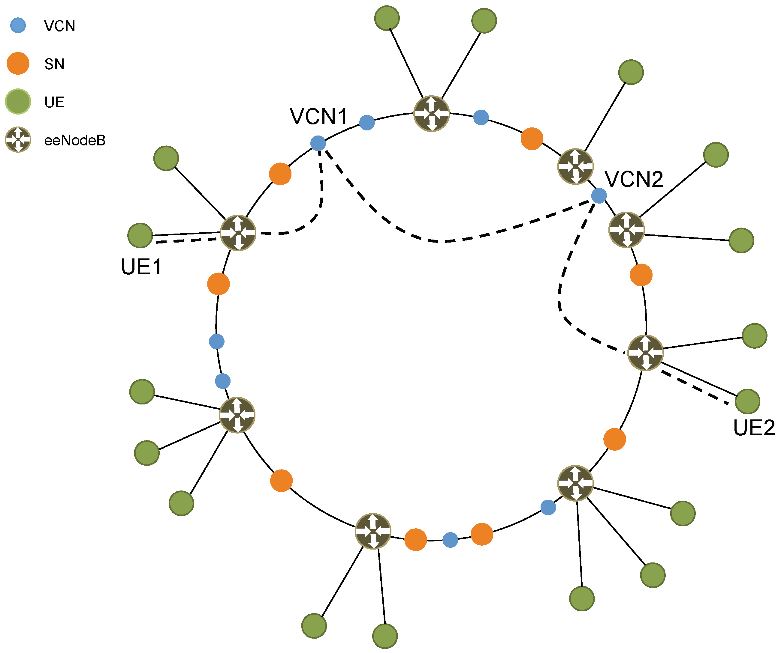
1], by leveraging the flexibility of SDN and NFV, one can propose a different virtualized architecture of the core network. In this architecture, each UE gets its own “private” virtual copy of the Enhanced Packet Core (EPC) which we call Virtual Core Network (VCN). In particular, as we show in
Figure 3, the proposed core network is a P2P network of VMs. Each VM functions as either a SuperNode (SN) or a VCN. By leveraging NFV, SNs and VCNs implement all the typical functions of an EPC (e.g., Mobility Management Entity (MME), Serving Gateway (S-GW), PDN Gateway (P-GW), Home Subscriber Server (HSS)). In particular, a VCN serves a single UE and typically has a short lifetime, while an SN serving a group of UEs is responsible for assigning VCNs to UEs and has a very long lifetime.
In this paper, we present and discuss the VCN architecture shown in
Figure 3. This new architecture presents many challenges, but, at the same time, has many significant advantages over the current architecture. Thanks to its highly distributed and personalized nature, the new architecture can, for example, disable cellular botnets from performing Distributed Denial of Service (DDoS) attacks. In addition, it allows the implementation of per-UE custom security and services. In particular, it is now possible, for example, to host an UE’s core network (i.e., its VCN) on: public cloud infrastructure (e.g., Microsoft Azure, Amazon AWS); private cloud infrastructure (e.g., enterprise, Government); cellular operator infrastructure. Furthermore, due to its single IP-layer architecture (see
Section 3.3) and VCN’s live migration capability (see
Section 7), the new core network improves on overall latency and delay.
Besides classical eNodeBs, we also consider a second scenario with an enhanced eNodeB, thus breaking the assumption of backwards compatibility with existing access networks. Furthermore, we discuss additional aspects of the new architecture such as IP addressing and non-security-related novel services enabled by the new architecture. Finally, we add additional cellular traffic measurements in order to better study the feasibility of the new architecture and fine-tune some of its most critical parameters.
The rest of the paper is organized as follows. In
Section 2, we briefly discuss current efforts in cellular core network technology.
Section 3 introduces our new architecture and its main elements, while in
Section 4 we discuss IP addressing in the new architecture. In
Section 5, we present message flows for basic operations of the cellular network (e.g., registering, making a call), while
Section 6 discusses in detail the concept of “UE redirection”.
Section 7 introduces a new type of mobility management and
Section 8 presents some high level considerations on scalability. Relevant advantages of the new architecture are discussed in
Section 9 and
Section 10, with a particular focus on security. In
Section 11, we present experimental measurements and related architectural considerations. Finally,
Section 12 concludes the paper.
2. Related Work
The scientific community and various standardization bodies (e.g., 5GPPP) have focused their attention and efforts towards new access networks for next-generation cellular networks [
2,
3,
4]. In particular, many approaches focus on harmonizing different access technologies (e.g., LiWi, WiFi, LTE) [
5], while others focus on improving spectrum efficiency [
6,
7] also by deploying micro-cells and pico-cells [
8,
9] with significant focus being given to mm-wave [
10,
11].
In the cellular core network, on the other hand, changes have been more incremental. In recent times, the most significant innovation has been the introduction of SDN and NFV. By leveraging SDN and NFV, relevant efforts focus on re-organizing the core network of operators and virtual operators on the cloud [
12] and in many other ways [
13,
14], but without changing the architecture which remains the same, although virtualized. In [
15], the authors go in the opposite and more drastic direction of completely removing the core network, by having eNodeBs directly accessing the public Internet.
We re-think the cellular core network and propose a new virtualized P2P architecture. This architecture still leverages SDN and NFV but does not follow the same thirty-year-old blueprint used by existing and past cellular networks. In doing so, we provide a new level of network security and flexibility as well as novel services that would not be possible otherwise.
3. A Novel Architecture
Unlike current efforts that propose to virtualize single elements of the existing core network architecture (see
Figure 2), we propose a completely different and novel virtualized architecture.
The new core network is a P2P network of VMs, where each VM can have the role of either an SN or a VCN. An SN is responsible for managing a certain number of UEs. In particular, it performs basic tasks (i.e., paging, voicemail and SMS delivery) as well as complex orchestration tasks (i.e., creating and destroying VMs that run VCN functionality). A VCN, on the other hand, is assigned to a single UE and provides voice and data services to that UE. Once a UE is associated with a VCN, the VCN takes over all tasks, including those previously handled by the SN with the exception of orchestration.
We envision two scenarios in the proposed architecture. In the
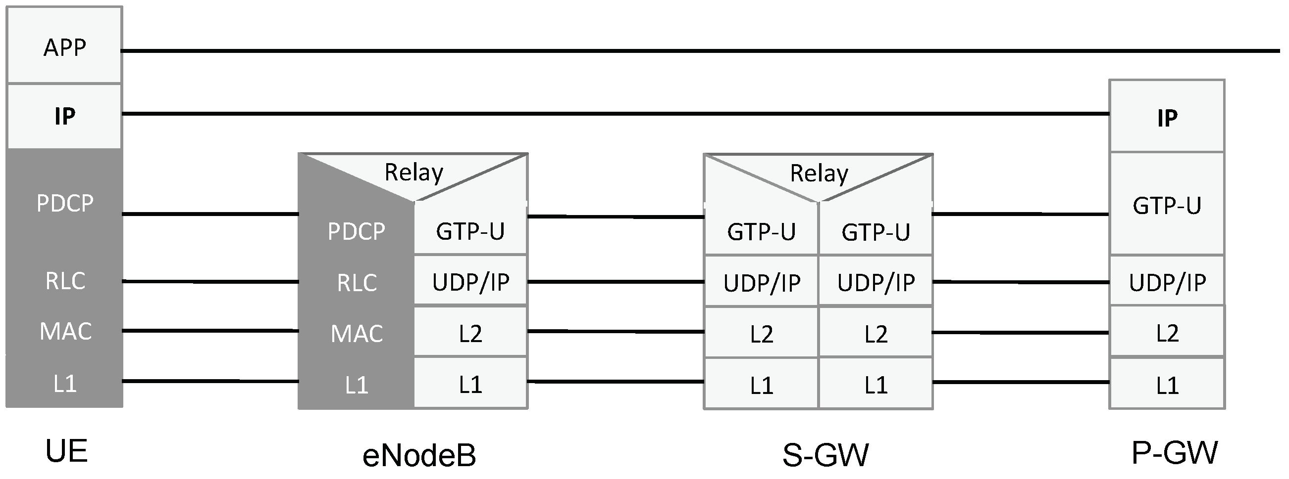
first scenario, we keep the existing protocol stack based on tunneling, in order to maintain compatibility with the existing access networks. Due to historical reasons, in current cellular core networks, tunneling is heavily used at a very fine granularity. For example, in the downlink, UE’s IP packets are fragmented and encapsulated in GPRS Tunneling Protocol (GTP) tunnels over UDP: in other words, the UE’s IP layer is encapsulated over the underlying IP layer of the Multi-Protocol Label Switching (MPLS) core network. This encapsulation is shown in
Figure 4. Furthermore, a single UE often uses multiple tunnels to different gateways. This is highly inefficient and leads to high latency and long delays regardless of the access network. In the
second scenario, we remove the assumption of backwards-compatibility with existing access networks and introduce an enhanced eNodeB (eeNodeB). In doing so, we introduce a single MPLS network, with IP on top, for both core network nodes (i.e., SNs and VCNs) and UEs, thus avoiding the IP-in-IP tunneling typical of today’s core networks.
Figure 5a,b show the protocol stack of a new Core Network Node (CNN) for the user plane and the control plane, respectively. As mentioned above, when using the eeNodeB, the new core network uses MPLS with IP on top for both CNNs and UEs, and no IP-in-IP tunneling. Above IP, the usual transport layer protocols are considered and, at the application layer, CNNs must support RELOAD [
16], SIP [
17] and P2PSIP (peer-to-peer version of SIP which relies on the RELOAD overlay) [
18] in the control plane and RTP and RTP-related protocols in the user plane. As will be described in more detail in
Section 5, RELOAD is used in order for the UE to attach to the network, while SIP and P2PSIP are used for Voice over LTE (VoLTE) call session setup. On the other hand, RTP is used for real-time media since a VCN always remains in the media path of a call.
Let us now look at the main three elements of the new architecture: SN, VCN, and eeNodeB.
3.1. SuperNode
A new user (UE) subscribing for service to a cellular network operator must provide some information (e.g., personal information, billing, SIM data) which is added to the cellular operator’s customer database and provisioned to an SN in the P2P network. How the provisioning mechanism and the SN selection process work are out of scope and reserved for future study. The operator’s customer database is a distributed database and is hosted on the operator’s private cloud. Such private cloud is separate from the cellular core network hosting infrastructure. Lastly, the customer database is also used to routinely store and backup UE’s state.
The Distributed Hash Table (DHT) used in the P2P core network can be any DHT characterized by the pair
. In particular, the
key is an
, where the International Mobile Subscriber Identifier (IMSI) is a unique identifier assigned to a subscriber [
19], and the corresponding
value is a URL pointing to the UE’s entry in the customer database.
The number of active SNs can vary over time depending on various factors such as network load, security, and maintenance. Every time a new SN is added to the P2P network, the DHT re-organizes itself and the new SN gets a list of entries in the DHT containing pointers to the customer database. By having such information, the new SN can retrieve the current state of all the UEs it has to serve from that moment on.
As summarized in
Figure 6a, SNs in the P2P core network serve the following four different purposes:
The SN is the UE’s first point of attachment to the core network. As such, the SN is responsible for the UE authentication during the attachment phase. In particular, the SN behaves as a standard EPC and performs the standard authentication process. On a successful authentication, a default bearer is established between SN and UE. The attachment procedure is further discussed in
Section 5.
After a successful authentication and attachment between UE and network, if the UE is not associated with a dedicated VCN, all basic signaling and “light-weight” tasks such as paging, SMS, push services (e.g., email notifications), voicemail, are handled by the SN the UE authenticated with.
An SN covers also the role of orchestrator for its UEs by creating and destroying VCNs and redirecting traffic accordingly. In particular, when a UE changes its state to
active (e.g., by initiating or receiving a call, by browsing the Internet), its SN deploys a new VCN dedicated to that UE, updates the DHT accordingly (i.e., the UE is now reachable at its VCN) and informs the eNodeB (or eeNodeB) to redirect all traffic for that UE to the UE’s VCN. On the other hand, once a UE goes back to
idle state and stays in such state for a certain amount of time (see
Section 11), the SN destroys the VM hosting the UE’s VCN and triggers a “redirect” at the eNodeB. From that point on, all data and signaling for that UE are again sent to the SN.
The SN also acts as an SIP Registrar and re-direct server. In particular, after a successful attachment to the network and successful authentication with the SN, the UE performs an SIP registration with the SN. This registration allows the UE to be reachable for VoLTE service as per standard SIP operations. The re-direct server functionality, on the other hand, is used for redirecting the UE to the VCN and back to the SN, as described in
Section 6.
3.2. Virtual Core Network
A VCN is dedicated to a single UE and handles: real-time media, data traffic and SIP signaling as well as all other functionalities that are typical of an EPC.
Figure 6b summarizes the different behaviors of a VCN. In particular, when using a legacy eNodeB, a VCN implements a dedicated IMS core for VoLTE and a dedicated EPC for Internet access and all non-voice data traffic. When using an eeNodeB, a VCN implements: (i) a dedicated SIP Proxy server and an SIP Back-to-Back User Agent (B2BUA) for VoLTE and (ii) a dedicated Internet gateway for Internet access and all non-voice data traffic. The SIP B2BUA functionality is required as we want the VCN to remain in the call data-path. We will discuss call establishment in
Section 5.
3.3. Enhanced eNodeB
The key idea behind the eeNodeB is to modify the interface between eNodeB and core network to better take advantage of the new core network architecture. In particular,
Figure 7a,b show the protocol stacks for the eeNodeB referring to both user and control planes, respectively. As one can see, in the user plane, the eeNodeB behaves essentially as an MPLS router while, in the control plane, it can “talk” directly to the P2P core network. In particular, in the latter case, it interacts with the P2P core network (i.e., queries the DHT) in order to identify the correct SN for a given UE and to route the traffic accordingly. Moreover, it handles redirects for traffic flows and notifies an SN of specific events (e.g., the UE has moved).
It is important to note that the LTE Uu interface between UE and eeNodeB has not been modified and is identical to that between UE and legacy eNodeB. This makes the new eeNodeB backwards-compatible with existing UEs.
4. IP Addressing
An SN uses a private IP address space with its UEs and VCNs. In particular, in
Figure 8 and
Figure 9, the IP addresses labeled with an
IN suffix belong to the private address space, while the ones labeled with an
OUT suffix are public IP addresses as they have to be routable.
The IP address of the UE (i.e., a private IP address) does not change when switching between SN and VCN as it does not change its SIP Proxy server’s IP address. This greatly simplifies the re-direction between VCN and SN, in terms of SIP and SDP payload, since the SDP information contained in the INVITE does not need to be modified when moving from SN to VCN. As we discuss in
Section 6, the IP address of the default gateway (i.e., P-GW) can also be left unchanged when moving between SN and VCN. On the other hand, the IP addresses of the SN’s Mobility Management Entity (MME) and of the VCN’s MME need to be different. This is because, in order for the EPS bearer update procedure to work (see
Section 6), the two MMEs need to be independently addressable by the eNodeB.
When a UE “moves” between SN and VCN, the external IP address of the UE changes as SN and VCN have different public IP addresses (i.e., addresses labeled with an
OUT suffix in
Figure 8 and
Figure 9). This breaks all existing TCP connections: while this may seem a negligible issue, we have to remember that, today, smartphones keep several TCP connections open in order to enable, for example, push services. In order to address this issue, we create a tunnel between SN and UE so that data on existing TCP connections are forwarded by the SN to the VCN and from this to the UE (see
Figure 10). Once all the “old” TCP connections have timed-out or have been closed, the tunnel is terminated by the SN.
5. Basic Operations
We now describe some of the basic message flows in the new architecture. We do this by considering two different scenarios. In the first scenario, we consider standard eNodeBs, while, in the second scenario, we consider the new eeNodeBs.
5.1. UE Attachment and SIP Registration
Generally speaking, in order to get Internet access, a UE needs to be attached to and authenticated with the cellular network. For VoLTE service, it also needs to be successfully registered with the IMS (i.e., with its SIP Registrar).
5.1.1. Scenario with eNodeB
In the current cellular architecture, when an eNodeB receives an attach request by a UE, it needs to discover which MME to connect to. This is usually done by querying an internal Domain Name System (iDNS) server which returns the IP address of the MME to use. Usually, one or more IP addresses of such DNS servers are either statically configured at each eNodeB or are provided to the eNodeB by a DHCP server, for example. Once the eNodeB connects to the MME, during the UE attach, the MME queries the iDNS server in order to discover which P-GW and S-GW to use in order to serve the UE [
20].
Figure 11 shows, at a high level, how UE attachment and SIP registration (A simplified SIP registration flow is shown for improved readability.) work in the new architecture when using a legacy eNodeB. In particular, when receiving an attach request from a UE, the eNodeB queries the network iDNS server to discover which SN (i.e., its MME) to talk to for that UE and, once discovered, UE and network perform the usual attach procedure. In particular, the eNodeB is not aware of talking to an SN, but, as far as it is concerned, it is “talking” to a traditional MME which, as per standard protocol, will direct it to a P-GW and S-GW. Once the attachment procedure completes, SIP authentication and registration can take place as per IMS standard [
21]. In the proposed architecture, the DNS server nodes are also nodes of the P2P core network and, while they expose a standard DNS interface to the eNodeBs, they resolve DSN queries by interrogating the DHT of the P2P core network. This can be achieved by translating between the DNS protocol and the P2P protocol (i.e., RELOAD) used by the core network and vice versa.
5.1.2. Scenario with eeNodeB
Figure 12 shows UE attachment and SIP registration when using an eeNodeB. In such a scenario, the eeNodeB can directly “talk” to the P2P core network and directly query the DHT in order to find the SN responsible for a specific UE: in other words, no iDNS is necessary. Furthermore, when using eeNodeBs, we do not have IP-in-IP tunneling and, therefore, the eeNodeB will only have to setup MPLS routes with the SN which are then used to route IP packets between the UE and the SN. The only bearer left, when using an eeNodeB, is the radio bearer on the
Uu interface between UE and eeNodeB. For establishing MPLS routes, the SN behaves as an SDN controller for that UE and takes care of establishing such routes by leveraging OpenFlow [
22], ReSource ReserVation Protocol-Traffic Engineering (RSVP-TE) [
23] or any other similar protocol.
In both scenarios (i.e., with eNodeB and with eeNodeB), once the UE performs an SIP registration with the SN, the SN updates the P2PSIP overlay with such information.
5.2. VoLTE Call Flow
We describe the steps involved in VoLTE call establishment in the new architecture. In particular, we present two scenarios, one with eNodeBs and the other with eeNodeBs.
5.2.1. Scenario with eNodeBs
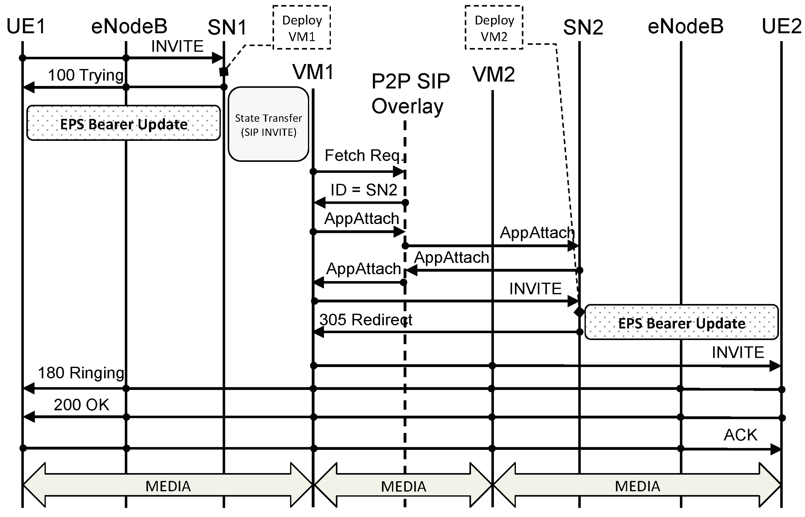
Figure 13 shows a VoLTE call setup message flow when using a legacy eNodeB. Given that in our new architecture the core network is a P2P network, we use P2PSIP as the signaling protocol for VoLTE calls. When UE1 wants to call UE2, UE1 sends an
INVITE to its outbound SIP Proxy server that is, to SN1. (In the UE, outbound SIP Proxy Servers can be configured either statically or dynamically via DHCP or DNS, for example.) When SN1 receives the
INVITE from UE1 it replies with a
100 TRYING to let UE1 know that it has received the
INVITE and to stop re-transmissions. At the same time, SN1 deploys a VCN for UE1 and transfers UE1’s state, including security context and SIP state, to VCN1. An EPS bearer update is also triggered by SN1 in order for UE1 to be able to send and receive packets from VCN1. We discuss the EPS bearer update process in
Section 6. Once VCN1 is up and running, it queries the P2PSIP overlay in order to find which VCN is responsible for UE2’s Address of Record (An Address of Record is a unique SIP identifier in the form
user@domain.) (AoR). If the VCN of UE2 (i.e., VCN2) is already up and running, the P2PSIP overlay replies with the address of VCN2; if, on the other hand, VCN2 is not available, the P2PSIP overlay replies with SN2’s address. As per P2PSIP standard,
AppAttach messages are then exchanged so that the two nodes can directly talk to each other. A this point, assuming VCN2 is not yet available, VCN1 forwards the
INVITE to SN2. When SN2 receives the
INVITE, it deploys a VCN for UE2 (i.e., VCN2) and starts the EPS bearer update process. Simultaneously, SN2 replies to the
INVITE with a
305 REDIRECT informing VCN1 that it has to use VCN2 as inbound SIP Proxy for UE2. VCN1 then sends the
INVITE to VCN2 which forwards it to UE2. From this moment on, all SIP messages are routed directly from UE1 to VCN1 to VCN2 to UE2, and vice versa (see
Figure 14). It is important to remark how P2PSIP is used only for the discovery of the callee’s SN and VCN while subsequent signaling and data do not leverage the P2P overlay but are sent via the respective VCNs.
A few other considerations are in order. When SN1 deploys VCN1, it transfers SIP state to VCN1. Moreover, as explained in
Section 4, VCN1’s SIP Proxy server has the same private IP address of SN1’s (i.e., SIP_IP_IN). Furthermore, an EPS bearer update is performed. This means that, at the application layer, UE1 is completely unaware that this change from SN1 to VCN1 has occurred, as it will continue using the same SIP Proxy server’s IP address it was using before. The same thing, however, is not true for SN2 and VCN2. In particular, when VCN1 sends the
INVITE to SN2, it sends it to SN2’s public IP address (i.e., SIP_IP_OUT). This means that when VCN2 is up and running, SN2 will have to send a
305 REDIRECT in order for VCN1 to point to VCN2’s public IP address (i.e., SIP_IP_OUT) instead of SN2’s, given that these two are different. Therefore, in this case, transferring SIP state between SN2 and VCN2 is unnecessary, as the
305 REDIRECT triggers a re-transmission of the
INVITE. UE2, on the other hand, is still unaware, at the application layer, of the change between SN2 and VCN2 because it continues to see the same SIP Proxy server’s IP address (i.e., SIP_IP_IN).
5.2.2. Scenario with eeNodeBs
Figure 15 shows a VoLTE call setup message flow when using an eeNodeB. In this case, almost everything remains the same as with the legacy eNodeB. The only difference is in the way the re-direction between SN and VCN is performed: this no longer involves the UE (see
Section 6.2). At the lower layers, however, the use of an eeNodeB and the consequent absence of all bearers (except for the Radio bearer) significantly improve latency, as we do not have all the IP-in-IP tunnels typical of a bearer-based architecture.
5.3. Internet Access
As mentioned earlier, an SN handles basic tasks for multiple UEs. However, when one of these UEs starts some data intensive activities (e.g., photo uploads, audio and video streaming), its SN deploys a VM running a dedicated VCN for that UE and redirects the UE SIP signaling and routing (see
Section 6) to such VCN. From that moment on, the UE communicates with the outside world through its VCN. In particular, if a legacy eNodeB is used, the VCN behaves as a dedicated EPC; if, on the other hand, an eeNodeB is used, the VCN behaves as a dedicated Internet gateway. The respective standard procedures apply to both scenarios.
Once these data intensive tasks end, the VCN notifies the SN, which performs three main actions: it triggers a routing redirect in order to redirect all UE traffic to itself; it points the UE’s AoR back to itself by updating the P2PSIP DHT; it destroys the VM running the UE’s VCN as it is no longer needed.
6. Re-Direction
As described in
Section 4, when a UE UE “moves” between SN and VCN (i.e., when UE goes form
idle state into
active state and vice versa), IP routes and UE tunnels must be updated. In particular, we have two different scenarios: one when using a legacy eNodeB and another one when using an eeNodeB. Let us look at these two scenarios.
6.1. Scenario with eNodeB
Figure 8 and
Figure 9 show the high-level components of an SN and VCN, respectively, when using an eNodeB. In particular, we show the IP addresses relevant for UE operations and mobility. As mentioned earlier, when a UE attaches to the network, its eNodeB will identify which MME to talk to. The MME will then tell the eNodeB which S-GW and P-GW to talk to. Tunnels are then established between UE and P-GW and between UE and IMS (i.e., SIP proxy or P-CSCF). Such tunnels are also known as EPS bearer and IMS bearer, respectively. According to 3GPP terminology, a
bearer is a tunnel with an associated Quality of Service (QoS), and it may have either a short or long lifetime. As it can be evinced by
Figure 16, there are two types of bearers: default bearers and dedicated bearers. A default EPS bearer is created between UE and P-GW when the UE attaches to the network for the first time and remains as long as UE is attached. At the same time or as soon as the UE performs an SIP registration, a default IMS bearer is also created (for VoLTE service). Each default bearer has its dedicated IP address. When a VoLTE call is initiated, the default IMS bearer is used for the SIP signaling, while a new dedicated bearers with higher QoS are set-up for voice and/or video data traffic. One or multiple dedicated bearers, bundled together, are encapsulated (tunneled) on top of a default bearer, without requiring new dedicated IP addresses. Default bearers are established and switched through the core network by means of dedicated MPLS flows. For this reason, when a UE moves from an SN to a VCN, the EPS bearer, IMS bearer, and MPLS routing (MPLS flow tables) must be updated. In the eNodeB case, the MPLS routing is automatically updated as a consequence of the bearer update—this, however, is not true for the eeNodeB case, as will be discussed later.
6.1.1. EPS Bearer Update
When using a legacy eNodeB, we need to act within the constraints of the current 3GPP standards. In particular, the authors in [
24] define how a UE registered with an MME can move to a different MME belonging to the same MME pool area, and load re-balancing between MMEs is performed.
Regarding load balancing, a weight factor proportional to the probability of being selected by an eNodeB is associated with each MME. The higher the weight factor, the larger the number of UEs that will associate with that MME. In case the MME cannot handle any UE traffic, the weight factor is equal to zero. Each time an MME has to be removed from a MME pool area (i.e., for maintenance purpose), the connected UEs must be off-loaded to other MMEs of the same pool area. This is performed by initiating a S1 Release procedure specifying “load balancing with TAU required”. This procedure triggers a Tracking Area Update (TAU) at the UE side making the eNodeB select a new MME based on the weight factors of all MMEs in the pool. A new EPS bearer is then established between the UE and the new P-GW.
In our scenario, in order to execute such a procedure, the MMEs of either SN and VCNs have to belong to the same pool. When a SN has to “redirect” a UE to a VCN, it starts a load re-balancing procedure, and the VCN sets the weight factor for its MME to a high value, while all other weight factors are kept unchanged. This weight factor is kept high until the UE is properly re-connected. For further improving the efficiency of this procedure, the SN may set a different MME pool for each VCN so that, at any time, in the pool, there are only the SN MME and one VCN MME. In this case, the SN MME would have to be part of multiple MME pool areas. The same procedure can be used for re-directing back the UE from the VCN MME to the SN MME.
6.1.2. IMS Bearer Update
As already stated, IMS and EPC use different bearers. When UE attaches to the network or when an SIP registration occurs, a default IMS bearer is established. When a UA moves from the SN to a VCN, the default IMS bearer is updated, while other actions must be performed at the application layer. In particular, the SIP Proxy’s IP address used by the SIP UA for connecting to the IMS must be updated with the address of SIP Proxy server of the VCN. However, this task can be easily solved by letting the two SIP Proxy addresses coincide. This is possible without any conflict since the bearer establishes a dedicated circuit pointing either the SN or the VCN, and the SIP Proxies must not be reachable by the UA at the same time.
6.2. Scenario with eeNodeB
Figure 17 shows the high-level architecture of a CNN when using an eeNodeB. Similarly to the previous scenario, the SIP proxy server behaves as a Registrar and Redirect server for the SN, while it behaves as a B2BUA for a VCN. The EPC, on the other hand, has now collapsed into a simple Internet gateway.
As mentioned in
Section 3.3, we do not modify the
Uu interface between UE and eeNodeB. This means that, when a redirection takes place, it will not involve the UE. The UE will be unaware of any change taking place while eeNodeB and SN will make sure traffic is redirected accordingly. In particular, as shown in
Figure 7a,b and as described in
Section 3.3, the eeNodeB is an MPLS router on the user plane and supports P2P protocols on the control plane in order to be able to talk to the P2P overlay of the core network (e.g., RELOAD). When a redirect for a UE needs to take place, the SN behaves as an SDN controller for that UE and it updates the MPLS flow tables accordingly so as to route the UE traffic to its VCN. This can be accomplished by leveraging existing protocols such as OpenFlow and RSVP-TE. At the application layer, the SN updates the information in the P2PSIP DHT in order to point the UE’s AoR to the newly created VCN. In this case, the UE is completely unaware of this change taking place. As before, the UE’s IP address, the SIP Proxy server’s IP address and the Internet gateway’s IP address do not change. The underlying MPLS network takes care of re-routing the traffic from the SN to the VCN.
7. Mobility
Mobility management in today’s cellular networks is a major component of the cellular infrastructure. In particular, the access network is split in Tracking Areas (TAs) and the MME keeps track of which UEs are in which TAs. Whenever a UE changes TA, it notifies the network which records the new TA for that UE. If a UE needs to be reached by the network (e.g., incoming call), the network pages the UE in the last known TA for that UE. This, together with handover management, makes mobility possible in the cellular network.
One downside of this architecture is that, as the UE moves around, the signaling has to always reach the EPC infrastructure in the datacenter to which the UE is assigned. This means that, when a user from New York goes to LA and makes a call, the signaling has to go all the way to the datacenter in New York and back to LA. This clearly introduces high delays and long Round Trip Time (RTT).
In our new architecture, we propose a significantly different approach to mobility, borrowing concepts from Content Distribution Networks [
25]. In particular, we try to deploy a VCN as close to the UE as possible in order to minimize latency and RTT. We distinguish between pre-call mobility and mid-call mobility.
In pre-call mobility, the UE is in idle mode and notifies its SN of changes in TA. When this happens, the SN searches and selects the available hosting infrastructure closest to the UE’s new location: if needed, the SN will deploy there a VCN. When the UE goes into active mode, the SN carries out this deployment.
In mid-call mobility, the UE is in active mode (e.g., in the middle of a call) and, as the user moves, the UE changes TA. Because the UE is in active mode, it has already been re-directed to a VCN and, as such, notifies the VCN of the change in TA. On receiving this TA update (TAU), the VCN notifies its SN by forwarding the TAU to it. When the SN receives the TAU from the VCN, it searches and identifies a new hosting infrastructure as close as possible to the UE’s new location. Once this infrastructure has been identified, the SN starts a live migration [
26] of the VM hosting the UE’s VCN to a VM hosted in the new infrastructure—all standard live-migration techniques can be applied [
27,
28,
29]. At the MPLS layer, flow tables must be updated accordingly in order to enable routing to the VCN’s new location. As mentioned in
Section 6.2, this can be enabled by the SN acting as an SDN controller and leveraging protocols such as OpenFlow and RSVP-TE.
The hosting infrastructure closest to the UE’s new location (i.e., its new TA) can be discovered by relying on any of the existing protocols used for location-based services, such as Location-to-Service Translation (LoST) [
30,
31] and DNS [
32]. The identified hosting infrastructure can be either: a datacenter of the cellular operator; a specific eNodeB, provided that this has VM hosting capabilities (e.g., fog computing); or anything in between. In particular, for high-profile users (e.g., Government), VCNs can be hosted on private cloud infrastructures not operated by the network operator, hardened with their own security measures in order to achieve a higher level of privacy and security for the UE. For such private infrastructures, the network operator would only retain a control interface between SN and VCN in order to initiate and terminate VCN deployment. In particular, as described in
Section 5.2, media is exchanged directly between VCNs and UEs with no SN involvement, thus preserving privacy and confidentiality.
8. Scalability
Due to the very large amount of connected devices that a network operator has to manage (also of the order of 100 million), a
statically assigned dedicated core network to each UE might easily lead to scalability problems. Our architecture overcomes this issue by assigning a VCN to a UA only for a limited amount of time. After the UA comes back to the
idle state and persists for a while, the UA is connected back to its SN, while the VCN is destroyed. As shown in
Section 11, this mechanism drastically improves the scalability.
A VCN instance can be created on a physical node by using one of the following mechanisms: VMs, containers, clear containers [
33], or separated processes. The choice of the mechanism to use depends on different factors and usually it is a trade-off between scalability and isolation.
Running VCN instances simply through different processes maximizes, of course, the scalability, but it guarantees very little isolation. From a security point of view, this solution requires a very high level of trust (and protection) of the underlying OS. For this reason, the choice of this solution will strongly depend on the type of network and system which VCNs have to be deployed in and on the corresponding threat model.
A solution based on containers guarantees higher isolation than processes, while it still very easy to deploy and performs very well in terms of scalability with respect to other virtualization mechanisms. The main drawback is that it still relies on a high level of trust in the underlying OS. Moreover, a particular attention must be payed to the rights assigned to the various containers: a container with root privileges may compromise the security of all other containers running on the machine.
A possible alternative is the use of
clear containers that provide the same characteristics and properties in terms of flexibility and scalability with respect to traditional containers, while they guarantee stronger isolation, of the same level of classical VM, by exploiting various kernel level features and CPU support. From a scalability point of view, results have shown that a clear container can be launched in less than 150 ms and has a memory footprint of about 20 MB, allowing the running up to 3500 clear containers on a single machine with 128 GB of RAM. (Source:
https://clearlinux.org/features/clear-containers) Although it cannot be considered yet as a “large scale” solution yet, it is very promising since it seems to combine the best of two opposite approaches, i.e., “classical” containers and VMs.
In terms of isolation, the strongest solution is the use of classical VMs. Unfortunately, it comes at the cost of higher CPU and memory consumption, leading to a limited scalability. However, for scenarios with a small user population, this solution can be attractive too. Moreover, in some cases, a combination of these different mechanisms can be also considered: for example, containers running in VMs.
Another parameter that has to be taken into account is the delay in setting-up the VCN. Amongst the four different mechanisms, the one that may require longer set-up time is the use of VMs. In order to reduce this delay, a technique similar to the thread-pool pattern used in multi-threaded programming can be used. A pool of idle VMs containing an already configured VCN can be maintained by each SN. Then, when a new VCN is requested, the SN has just to load the UE state and data into one VM (HSS data, billing, etc.) and make the VM reachable.
Some measurement results will be shown in
Section 11, together with some consideration on scalability and other issues related to real-world mobile networks.
9. VCNs and Core Network Security
The current architecture of mobile core networks is reactive, i.e., it reacts to events when they occur. For example, when high traffic to the HLR is detected, the network may react by spawning additional VMs running new instances of the HLR. On the contrary, the proposed architecture is proactive by design.
From the security point of view, the isolation of VCNs prevents the occurrence of some types of attacks. For example, if a cellular botnet composed of several UEs tries to carry out a DDoS attack, the attack would be restricted to the VCNs connected to the bots, with each bot performing the attack with its VCN. As a result, the DDoS would fail (left side of
Figure 18). Instead, if a DDoS attack targeted to a core network is carried out from external nodes (for example attached to the external Internet), it may occur but it will be limited to a single VCN and will affect only one user (refer to the right side of
Figure 18). All other users remain unaffected by the attack. Moreover, the VCN under attack can be easily isolated and replaced by a fresh VCN. The attacked VCN can be destroyed or used to study the attack and identify the attacker. The same result would be reached if a malware in some way succeeds in infecting a core network element: at most, only the corresponding core network would “crash”, leaving all the VCNs and UEs unaffected.
There are also other types of attacks that a cellular botnet (formed by compromised UEs) can carry out. For example, a cellular botnet may try to perform a “low bitrate” attack against a SN: such an attack can be executed for example via SMS messages without triggering re-direction of UEs to a VCN, and affecting all the UEs associated with the targeted SN. However, the main difficulty in carrying out this attack is to be able to target a sufficient number of UEs associated with the same SN, since generally these associations can be established randomly (the SN for each UE can be selected randomly out of a pool of SNs). Moreover, in case the attack succeeds, it can be easily solved by letting UEs of the SN partially or totally migrate to a new SN, making the attack no longer effective. The compromised SN could be destroyed and the DHT updated accordingly.
Another type of DoS attack could be the exploitation of the redirection of UEs from SN to VCNs as a consequence of the switching from
idle to
active state. Forcing such a switching operation, the attack may have two effects: (i) overload the core network with unnecessary orchestration and signaling traffic; and (ii) increase the lifetime of the VCNs (
Section 11. We saw that a VCN is destroyed only when the UE has come back to idle mode and stayed in that state for a certain amount of time) that, in turn, has the effect of increasing the number of active VCNs and the corresponding amount of required resources.
By increasing the idle mode time required for triggering the removal of a VCN and the transition of the UE back to the SN, it is possible to make the VCN-to-SN switching rate too low for letting the first result of the attack (unnecessary orchestration and signaling traffic) to be effective. However, this timeout must be carefully selected since it has an impact also on the total number active VCNs and resource consumption. Fortunately, this attack starts to have an effect only when a very large botnet is used (millions of bots/compromised UEs) and this is an extremely unlikely scenario. However, also in that case, some countermeasures do exist.
Having a single VCN per UE has another interesting feature related to security: security mechanisms implemented within the VCN can be highly customized for each single user. Some basic users may not be interested in encrypted data communications, reducing the required CPU time, while other users may require a higher level of security in terms of stronger authentication, encryption, and other security services. Firewall rules can also be customized for each single UE. Particular types of traffic can be enabled, e.g., to let the UE act as server or to enable M2M communications, while other types of traffic can be filtered, in order to block some services or to protect the UE and VCN against particular types of attacks and malware.
Similarly, as mentioned in
Section 7, the infrastructure used for running VCNs may vary depending on the user scenario. For example, private cloud infrastructure, together with strict local security policies and stronger encryption, can be used when a high security level is required (e.g., Government, enterprise), while a public cloud infrastructure (e.g., Amazon AWS), a cellular operator hosting infrastructure, or eNodeBs with hosting capabilities (e.g., edge cloud, fog computing) could also be used for hosting VCNs of other users. Furthermore, in the case of multi-SIM UEs, one user may be associated, at the same time, with multiple core networks hosted in different clouds. If an external hosting infrastructure (either public or private) is used to host some VCNs (see
Figure 19), the network operator would only keep control on setting up and tearing down the VCNs, and managing some billing and administration operation. This, together with specific service level agreements with cloud operators, would enable the cellular operator to provide a new class of custom security services while, at the same time, reducing operational cost.
10. Other Advantages
Let us summarize some of the non-security-related advantages the new architecture brings.
By assigning a VCN to each UE, we can now assign network resources at the user level. In particular, not all users need all the capabilities a cellular network has to offer. For example, some users are static or nomadic while others are highly mobile. This means that a UE may have no need for high mobility management and, as such, this functionality may be stripped out of its VCN. Similarly, a user may have no need for paging as, perhaps, it is not supposed to receive notifications or calls (e.g., possible in some machine-to-machine scenarios). In such a case, the paging functionality could also be stripped out of the UE’s VCN, further reducing its complexity. Another UE may still not need VoLTE services but just Internet access: this would allow the removal of all IMS-related functionalities from the UE’s VCN. In other words, the proposed architecture allows for customization of the cellular core network at the UE level, giving a much more personalized experience and services. This is beneficial for both the user and the network operator as it allows for new business models and, at the same time, simplifies operations. In addition, it reduces VCN complexity, simultaneously reducing the VCN’s attack surface.
As mentioned earlier, in today’s cellular networks, when a user travels from New York to Los Angeles, for example, whenever he/she makes a call, the signaling has to go all the way to New York and back to Los Angeles, introducing greater latency and delays. To make things worse, as discussed in
Section 6, each UE establishes multiple IP-in-IP tunnels with the core network, further adding to RTT and delays. By using the proposed architecture, these two sources of delay are no longer present. In particular, as discussed in
Section 6, by removing all bearers in the core network and simplifying the core network into one single MPLS network, there are no more multiple fine-grained tunnels to be established by the UE. In addition, as discussed in
Section 7, by having a VCN per UE, we can “move” the VCN as close to a UE as possible, further reducing latency and delay due to physical distance.
The current core network architecture, virtualized or not, has a bottleneck at the datacenter where all traffic converges with consequent load peaks and, potentially, service degradation. On the other hand, as we show in
Figure 19, our core network architecture is distributed and very dynamic, as VCNs can be deployed in different hosting infrastructures and datacenters and can be moved as needed. This minimizes load peaks and avoids bottlenecks turning VCNs placement into an optimization problem with many parameters to consider (e.g., distance from UE, current load at hosting infrastructure, security requirements).
Finally, a per-UE customization of the core network also helps in Operations and Management thanks to easier access to single-user traffic, easier billing, easier policy enforcement and more.
11. Measurements
In this section, we address two critical design issues: (i) the total number of entities required to accommodate the traffic of a given user population; and (ii) the life cycle of an entity from its creation to the destruction. Hereafter, we will refer to an “entity” as either a VM, a clear container, a container or a process (see
Section 8).
Dataset: For the analysis, we used a sample of fully anonymized Call Detail Records (CDRs) collected within a large cellular network provider in USA over a period of nine days from 10 February 2016 to 18 February 2016. The subset contains approximately 5,000,000 of experimental records related to 200,000 users within the entire population. User privacy has been protected by anonymizing the phone numbers through randomized unique identifiers. Each call record is formed by: the start time of the call; the caller and callee anonymized identifiers; the call duration. The following performance results are obtained by statistically analyzing, with Matlab, the CDRs.
Analysis 1: We first analyze the total number of entities needed for serving the traffic load required by the call records. We refer to
concurrent calls as active calls that fall into the same minute. In
Figure 20, the number of concurrent active calls over nine days is shown. As it is possible to see, a clear diurnal cycle is present: the daily minimum is around at 2:00 a.m.–3 a.m., while an increased call activity is achieved during working hours and early at night (from 9:00 a.m. to 9:00 p.m.). These characteristics are consistent with the study by Becker et al. [
34]. Starting from these data, we want to obtain the maximum number of concurrent calls in order to compute the maximum number of entities that need to be simultaneously active in the system. Because, during the two weekend days (13 and 14 February), the traffic is less than during weekdays, we will focus only on weekdays (seven days total).
For predicting the concurrent traffic load in the network, we use the seasonal AutoRegressive Integrated Moving Average (ARIMA), a simple time-series module. The set of seven days have been divided into six days for the training and one day for the test. Since we are interested in the maximum traffic load in the network, for each hour during the training, we keep the maximal count among the original non-aggregated data points. We use the R package
forecast [
35] to fit an ARIMA model to our hourly count time-series.
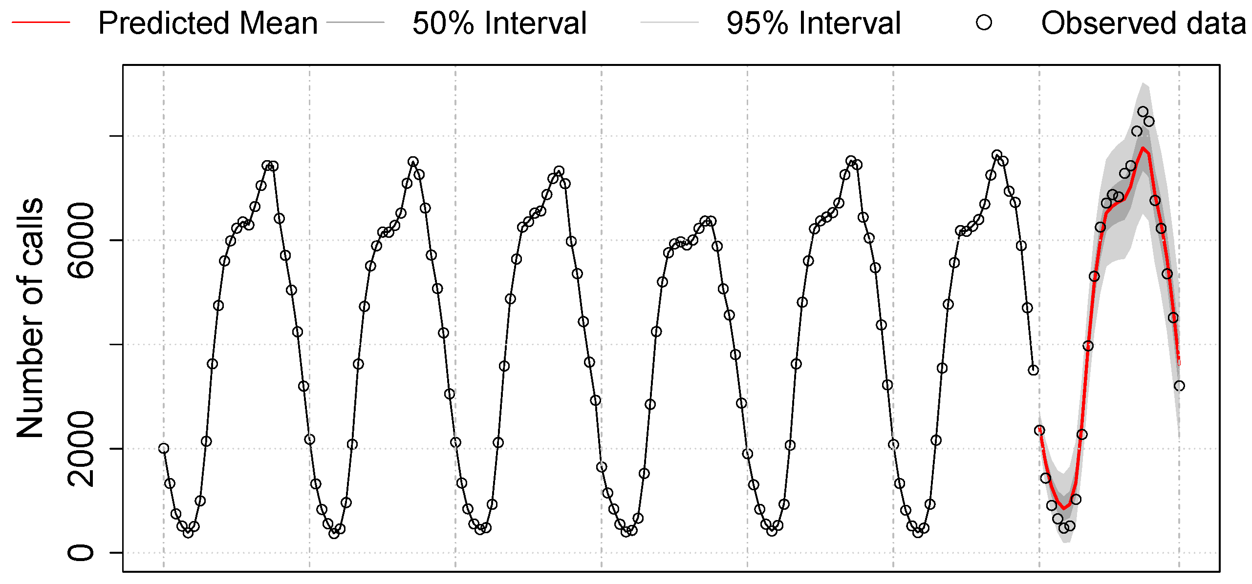
Figure 21 shows the forecast of one-day traffic according to the best ARIMA model learned from the training:
ARIMA . The solid red curve at the end of the graph represents the prediction of the next one-day per-hour call load. The two shaded areas, one smaller and one larger, represent prediction intervals of 50% and 95%, respectively. The true test data for one day lies within the 95% prediction interval with a maximum of 8400 concurrent calls, thus showing an accurate prediction. The highest count of the 95% interval represents 9126 concurrent calls, which correspond to ∼4.6% of the total number of users.
Recommendation 1: If both caller and callee use the proposed system, then each call will involve two VCNs: therefore, the maximum number of required VCNs is twice the maximum number of concurrent calls. On the basis of the previous model and assuming that VCNs are destroyed as soon as UEs move back to idle mode, the maximum number of simultaneously active entities (i.e., one entity per VCN) would be around 9.2% of the user population.
If a small or medium size of user population is using the network, on the order of hundreds of thousands of users, it is possible to use VMs to host VCNs. However, if the number of users increase up to hundreds of millions, other solutions such as containers and processes should be preferred, although this leads to a lower level of VCN isolation.
Analysis 2: We study users’ traffic patterns in order to determine the life cycle of an entity between its creation and its destruction. Given our sample of call records, we found some calls to be extremely short (shorter than ten seconds). One common pattern for these short calls is that two records of a phone number
A show the same start time and duration but with different phone numbers, that is, one towards phone number
B and one towards phone number
C. These cases correspond to calls for which the callee (i.e., phone number
A) does not answer the caller (i.e., phone number
B). Instead, the calls are redirected to voicemail (i.e., phone number
C), a service that stores voice messages. In such a case, setting up a VCN is inefficient as no real call happens. This suggests a change in our protocol for VoLTE calls (see
Section 5). In particular, instead of deploying a VCN when the SN receives an
INVITE, the VCN gets deployed once the SN receives the
200 OK to the
INVITE, that is, once the callee has accepted the call. For the rest of the analysis, we remove calls that last less than ten seconds.
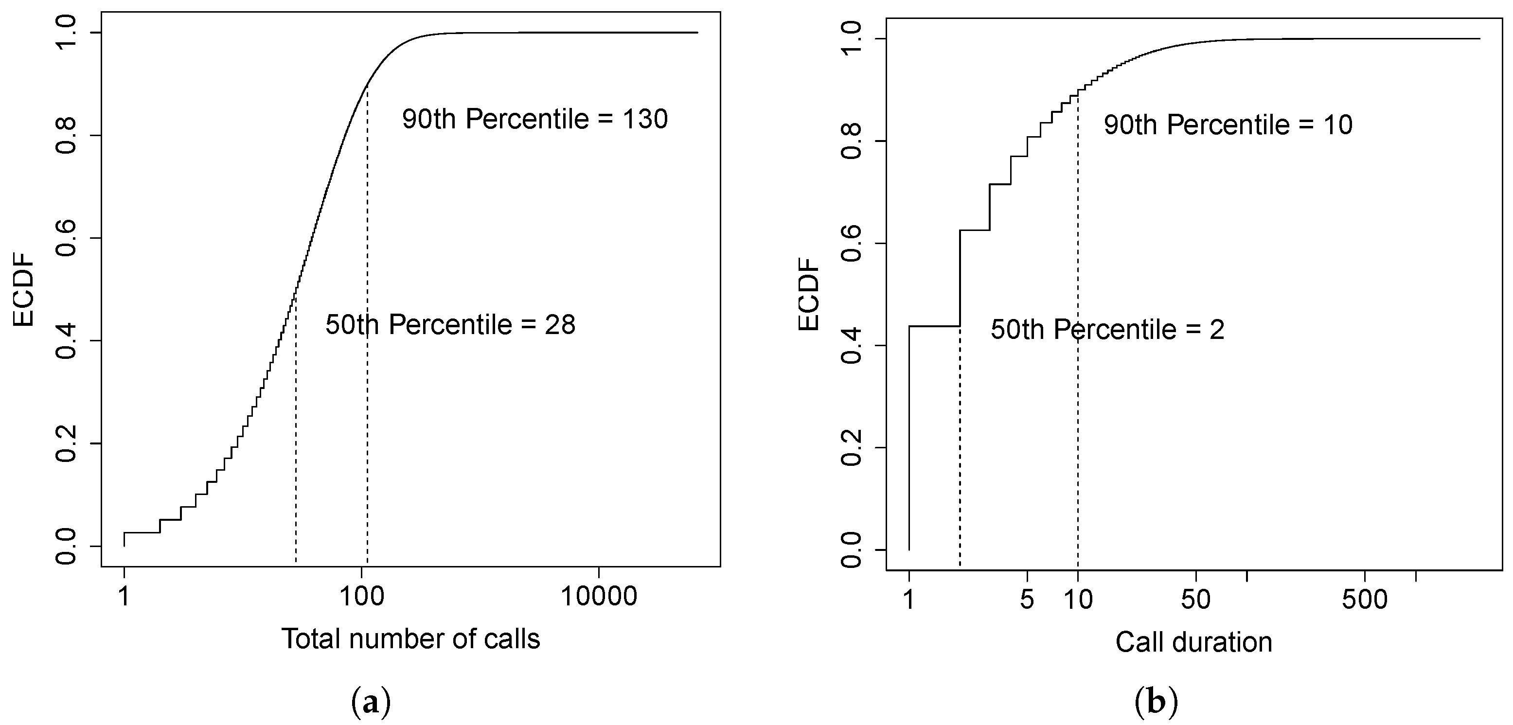
We measure the duration of a call in minutes.
Figure 22a,b show the Empirical Cumulative Distribution Function (ECDF) of the number of calls and call duration over a ten-day period, respectively. Notice that both the number of calls and the call duration are discrete variables; this makes the ECDF look like a step function. The median number of calls per user over ten days is 28, with approximately three calls per user per day. About
of the users have less than 130 calls over ten days (i.e., approximately 13 calls/day) which is consistent with the results in [
36]. The median of the call duration is two minutes and approximately 90% of the calls are less than ten minutes long. This means that the majority of the calls has a short duration, that is, the lifetime of an entity could be short if based only on the call duration. However, we need also to consider the time between calls since we do not want to destroy an entity just to find out that we have to deploy it again a few seconds later.
A
call interval is defined as the lag between the time a call terminates and the time the next call is placed, for a given user. As before, we measure the call interval in minutes.
Figure 23 shows the box-and-whisker plot of the ratio of calls with different call interval levels per user. The levels are indicated by the labels on the left side of the
y-axis. For example, a level of (2, 5] indicates a call interval that goes from above two to five minutes. The levels are evenly partitioned with a step size of five minutes, excluding the last level which represents a call interval longer than 30 min. The first 5-min level is further broken into two levels to show more details on very short call intervals (i.e., less than two minutes). The labels on the second
y-axis on the right indicate the percentage of outliers for each level (i.e., shown as black dots in the plot).
If the time interval between two calls is short, or if the majority of the calls are placed within a certain time interval, it may be inefficient to destroy the entity around that interval. For example, if a user places a call every three minutes, it is inefficient to destroy his VCN at the 2-minute mark as it will have to be deployed again 1 min later.
Recommendation 2: In
Figure 23, a small ratio value on the
x-axis for a given call interval tells us that the percentage of calls per user that have a time between calls as indicated by the interval on the
y-axis is small and, thus, unlikely. From our collected data sample, the median for interval not longer than two minutes is 8%, meaning that half of the users have 8% of the call intervals shorter than or equal to two minutes. The median and third quartile are 4% and 8%, respectively, for the next two call interval levels, i.e., (2, 5] and (5, 10]. The median for the
call interval level is 2% and the third quartile is 6%. It is encouraging to see that long call intervals (i.e., more-than-30-min bin) are the largest percentage of all call intervals. In particular, the median is 67%, meaning that half of the users have 67% of the call intervals longer than 30 min, with the first and third quartiles being 54% and 80%, respectively. In other words, this means that, if a VCN is idle for more than 10 min, we can destroy it and, with high probability, there will be no need to deploy it again for another 20 min or so. To conclude, it is reasonable to measure and use the user call interval patterns in order to determine the life cycle of an entity, i.e., its restart rate.
Summary: By combining both recommendations, we show how the maximum number of concurrent entities that the network must support is affected by both the number of concurrent calls and the amount of time the UE has to spend into
idle mode before its entity gets destroyed. By considering both conditions, we compare three cases: (i) the UE’s entity gets destroyed right after the UE goes back to idle mode; (ii) the UE’s entity gets destroyed five minutes after the UE goes back to idle mode; and (iii) the UE’s entity gets destroyed 10 min after the UE goes back to idle mode.
Figure 24 shows the average, over nine days, of the ratio between the maximum number of active entities reached in cases (ii) and (iii) over the one reached in case (i). From the results in
Figure 24, one can observe that: in case (ii), the maximum number of active entities in the network can be twice the number reached in case (i); in case (iii), the maximum number of active entities in the network can be three times the number reached in case (i). This means that, in case (ii), the maximum number of entities is roughly 20% of the user population, while it grows to about 30% in case (iii). Picking a threshold value sets a trade-off between entity restart rate and maximum number of active entities. A waiting time of 10 min would have a lower entity restart rate, but a quite large maximum number of active entities. A waiting time of five minutes, on the other hand, would still take care of most of the very short calls (as shown in
Figure 23), while keeping the maximum number of concurrent entities active in the network anywhere between 9% and 18% of the user population.
When to create and destroy VCNs, hence changing their number, is an optimization problem that, due to scalability, is critical to our new architecture. In order to study and estimate VCN scalability, we focused our analysis on voice-call traffic. In the future, we plan to enhance our traffic analysis with IP data traffic in order to estimate VCN scalability for non-voice data traffic and, in doing so, engineer a system optimized for all types of traffic.
12. Conclusions
Unlike the access network, the cellular core network has not really changed since the very first cellular networks. In this work, we have proposed a novel P2P dedicated virtual core network, describing in detail its architecture and operational characteristics. In the new virtual core network, one dedicated VCN is dynamically assigned to each UE, resulting in a much greater degree of flexibility, security and privacy. For example, from the security point of view, DDoS attacks by cellular botnets are prevented from being carrying on, while the damage of other attacks to a single UE can be limited, and the recovering is simplified. The proposed architecture allows also per-UE custom security and services (e.g., 3rd party VCN hosting), and can reduce network latency and RTT. Moreover, we have shown how an accurate prediction of the number of active VCNs and SNs required for a given scenario can be obtained through a proper ARIMA-based data analysis, relying on a large voice-call traffic database of a large U.S. cellular network provider.


