Abstract
Long Term Evolution networks, which are cellular networks, are subject to many impairments due to the nature of the transmission channel used, i.e. the air. Intercell interference is the main impairment faced by Long Term Evolution networks as it uses frequency reuse one scheme, where the whole bandwidth is used in each cell. In this paper, we propose a full dynamic intercell interference coordination scheme with no bandwidth partitioning for downlink Long Term Evolution networks. We use a reinforcement learning approach. The proposed scheme is a joint resource allocation and power allocation scheme and its purpose is to minimize intercell interference in Long Term Evolution networks. Performances of proposed scheme shows quality of service improvement in terms of SINR, packet loss and delay compared to other algorithms.
1. Introduction
Long Term Evolution (LTE) is the solution proposed by the 3GPP consortium to provide high data rates to users in order to satisfy high bandwidth demand. LTE is a 4G technology and uses IP technology for data transport. It supports 100 Mbps data rates in the downlink and 50 Mbps data rates in the uplink [1]. LTE uses frequency reuse factor one that leads to intercell interference (ICI) [2]. LTE uses Orthogonal Frequency Division Multiplexing Access (OFDMA) in the downlink and Single Carrier Frequency Division Multiplexing Access (SC-FDMA) in the uplink to eliminate intra-cell interferences. The bandwidth is divided into orthogonal narrowband subcarriers of 180 kHz separated by guard band of 15 kHz. The main radio impairment faced by LTE is intercell interference as it uses frequency reuse one scheme where all frequencies are used by each cell. Cell edge users are likely to suffer interference causing by neighboring cells transmitting at the same frequencies while receiving weak signals from their serving cell due to the path loss that is higher with the distance to the serving enodeB [3].
Intercell interference mitigation techniques are used to address the ICI problem. There are three approaches to intercell mitigation defined by the 3GPP consortium: intercell interference randomization, intercell interference cancellation and intercell-interference coordination/avoidance [4]. They can be combined in a system as their benefits are mutually exclusive [5]. The goal of intercell interference randomization is randomizing the interfering signals with cell-specific scrambling, cell-specific interleaving or frequency hopping. Intercell interference cancellation goal is to suppress interference at the user beyond what can be achieved by just exploiting the processing gain. This is done by using multiple antennas at the user or by detection and subtraction of the intercell interference. Intercell interference coordination/avoidance goal is to minimize intercell interference since it is impossible to prevent it as LTE uses reuse frequency 1 (RF1) scheme. This technique applies restrictions to the downlink resource management in a coordinated way between cells. Restrictions are made on transmit power and resource allocation both in time and frequency domain. The effect of these restrictions is the improvement of SINR, thus the data rate and coverage, especially for cell edges users.
Basic intercell interference coordination techniques use static schemes [6,7,8] where available bandwidth is partitioned among users within each cell thanks to frequency reuse schemes. This bandwidth partitioning divide users in cell edge users and cell center users. However, some techniques combine dynamic schemes with static schemes [9,10,11,12], dynamic schemes being used for cell edge users. Resources are likely to be waisted in some partitions if there are fewer users to use them, while users in other partitions could use them.
In this paper, a full dynamic intercell interference coordination in a multi-cell environment scheme that combines resource allocation and dynamic power control in the downlink using reinforcement learning is proposed. The proposed scheme does not use bandwidth partitioning. Reinforcement learning is a computational intelligence approach which belongs to machine learning and is used in many areas. Among these area, we have robotics, games, control, and operations research [13,14]. It has low computational requirements, medium memory requirements, high flexibility, and is optimal [15]. The proposed scheme has four steps: user selection, resource allocation, dynamic power control and packet to retransmit identification. We introduce a new way of handling packet retransmission, which, instead of waiting for a notification from the receiver, checks the channel conditions before sending a packet. When channel conditions are bad, the packet is immediately transferred in retransmission queue.
The rest of the paper is organized as follows. In Section 2, related woks on intercell interference coordination are presented. In Section 3, the problem formulation is presented. The system model is presented in Section 4. In Section 5, our proposed ICIC scheme is presented. In Section 6, results are presented and the conclusion follows in Section 7.
2. Related Work
Intercell interference being the main problem in LTE networks, intensive research has been carried out to address it. Surveys have been carried out on intercell interference mitigation techniques in LTE downlink networks [16,17], on intercell interference coordination techniques in OFDMA-based cellular networks [18] and on ICIC techniques in OFDMA based-cellular networks and LTE [19].
ICIC techniques can be classified in two groups [18]: static ICIC or frequency reuse based schemes and dynamic ICIC or cell coordination schemes.
In static ICIC schemes, a common technique is Fractional Frequency Reuse (FFR). Users are divided into two groups: cell edge users and center cell users. The available resources are divided into two groups: one group for cell edge users and one group for center cell users. FFR is divided into three main classes [18]: Partial Frequency Reuse (PFR) schemes, Soft Frequency Reuse (SFR) schemes and intelligent reuse schemes. Performance of reuse-1, reuse-3, FFR, and SFR are investigated regarding network load and user distribution in [20]. Some hybrid schemes associate a static scheme to another techniques, for example in [21] where the authors proposed a hybrid mechanism using Fractional Frequency Reuse (FFR) and Almost Blank Sub-frame (ABS) schemes to mitigate inter-cell interference caused to Device-to-Device (DUE-Rxs) receivers by cellular user equipments (CUEs) in sensor networks underlying LTE-A.
On the other side, coordination-based schemes can be categorized into four categories [18]: centralized, semi-distributed, coordinated-distributed, and autonomous-distributed. The level of coordination can be differentiated by four dimensions [18]: optimization objective, power control technique, channel allocation recommender and fairness to user. In [22], a joint resource block allocation and transmission power allocation in the uplink communication for multi-cell D2D enabled networks scheme is proposed. The proposed scheme uses bilateral symmetric interaction game for RB allocation problem and linear programming for the power allocation problem. In [23], the authors proposed a coordinated multi point interference mitigation scheme that uses destructive spatial phase coding as a pre-coding scheme to reduce the SNR. The scheme is proposed for heterogeneous OFDM networks.
Intercell interference coordination is an optimization problem that can be better addressed using computational intelligence (CI).
In this paper, we consider centralized cell coordination schemes. Obviously, the problem to solve in coordination schemes is resources allocation in multi-cells networks. Most studies addressing resource allocation found in the literature consider single cell networks. There are however some studies that consider multi cell networks.
In [24], an ICIC technique based on user’s ratio and frequency allocation is proposed for OFDM based networks. Cell-center users are allocated resources that are allocated to cell-edge users in neighboring cells. In [25], an ICIC scheme using downlink multi-cell chunk allocation with dynamic intercell coordination is proposed with two level-algorithm, at a base station and at a central controller.
In [26], a heuristic intercell coordination scheme for the uplink of LTE networks is proposed. The proposed scheme is formulated as an integer programming problem. The basic idea of the scheme is to switch users on and off to maximize a certain utility function. Coordination is carried out between two cells at a time, and then iterative improvement is implemented for the whole coordination. Power control is not done in this scheme. The scheme just mitigates the intercell interference by resource allocation. The performance of the scheme has been evaluated in terms of uplink average throughput and delay via Monte Carlo simulations with a two-cell network case. The proposed scheme has been compared with no coordination schemes using proportional fairness (PF) and round robin (RR) schedulers.
In [27], a joint resource block and transmit power allocation scheme in LTE downlink networks is proposed. Resource blocks are allocated to users based on their priority measured by interference level, quality of service and delay. The transmit power of enodeBs are then dynamically controlled using fuzzy logic system, considering messages exchanged between enodeBs over X2 interface. The proposed scheme has been compared to reuse factor one (RF1) SFR. In [28], a dynamic ICIC technique that uses dynamic resource allocation is proposed with no cooperation between base stations. Evaluation of the technique with a MATLAB®-based LTE downlink level simulator shows throughput fairness improvement compared to the reuse-1, FFR and SFR models.
In [29], role game theory is applied to uplink power control and ICIC for LTE where users are defined as having different roles within a cell of the LTE network. In [30], a genetic algorithm (GA) approach is proposed to optimize the resource block allocation in a multi-cell network. The aim of the approach is to minimize intercell interference by maximizing channel capacity in the resource allocation process. The cells are grouped in independent clusters and the resource allocation optimization is done cell by cell within a cluster. The authors exploited information exchanged over the X2 interface between cells within a cluster. The article shows the efficiency of the methods. Simulation results show that the interference of most users is decreased by 3 dB and the average throughput per cluster is increased by 21 Mbps according to the universal frequency reuse in a few iterations. In [31], a GA-based self-organized downlink resource allocation in a multi-cell LTE-Advanced Network is proposed. The aim of the optimization method is to mitigate the intercell interference by maximizing the throughput. The proposed algorithm is compared with the random allocation. A MATLAB® simulation program is used. The article shows that the proposed algorithm outperforms in terms of average user throughput and system fairness.
Listed related works use bandwidth partitioning, which distinguishes users based on their position relative to enodeB within a cell. Users are divided into cell edge users and cell center users. Portions of a bandwidth are reserved for users in coordination with neighboring cells. Basic ICIC schemes failed to consider real time services as they do not consider packet loss ratio as a property but rather focus on throughput maximization Besides, packet retransmission is not considered in the proposed schemes and most of them consider one step ICIC scheme like resource allocation or power allocation.
In this study, we propose a new ICIC scheme that does not partition bandwidth. The whole bandwidth is shared among users regardless for their position relative to the enodeB within serving cell making resource allocation an optimization problem. Resource allocation optimization problem is handled with the objective of minimizing intercell interference among neighboring cells. The proposed ICIC scheme, which is a joint resource allocation and power control optimization, is intended for real time services and consider packet retransmission.
3. Problem Formulation
Intercell interference is caused by multiple sources transmitting signals with the same subcarrier and received by a receiver. A user receives signals from the serving cell and neighboring cells but at different power levels due to the pathloss. The interference is measured by the Signal to interference plus noise ratio (SINR).
SINR for a user located on cell j can be expressed by [29]:
where is the path-loss exponent, is the transmit power of the serving enodeB j, n is the number of neighboring enodeBs, is the transmit power from the neighboring enodeBs, is the distance of the user to the serving station, is the distance of the user to each of the neighboring stations, and is the background noise with the thermal noise and B the system bandwidth.
Assuming a severe interference scenario, the background noise can be ignored [29]. The expression of SINR can then be rewritten as:
The expression of SINR shows that it depends on the distance between the user and the transmitter. It clearly appears that SINR for cell edge users will be low as channel gain for neighboring cells will be greater than transmit power of serving cell. In the case where each cell is transmitting with the same power level, cell edge users will experience low SINR as the distance between serving enodeB and some neighboring enodeBs are approximatively the same.
To ensure good quality signal received by a user, interference has to be minimized. Minimizing interference is the same thing as maximizing SINR value. This becomes an optimization problem.
From the expression of the SINR, it can be seen that it can be increased either by decreasing transmit power from neighboring cells or by increasing transmit power from serving cell. This can be done using power control by coordination between enodeBs through X2 interface.
The distance of a user from its serving enodeB and neighboring enodeBs also cannot be changed but transmit power from serving enodeB and neighboring enodeBs can be assigned different values to increase SINR value. Given that there are multiple neighboring enodeBs, it becomes mathematically difficult to get a solution of finding transmit power of serving enodeB and neighboring enodeBs when targeting a desired SINR value.
Heuristic methods are well suited for this kind of optimization problem. They use computational intelligence to find solution to optimization problems. Some heuristic methods that use computational intelligence are genetic algorithm (GA) [32], ant colony optimization (ACO) [33], swarm optimization (PSO) [34], simulated annealing (SA) [35], reinforcement learning (RL) [13], and decision tree [36].
A comparison of some CI approaches in [15] shows that reinforcement learning and swarm optimization have low computational requirements, medium memory requirements, high flexibility, and are optimal, thus are the best choices to consider for our optimization problem. Since LTE networks offer online services to users to users, these approaches cannot be used on live LTE networks because of the computation time they will require which will certainly lead to disasters. Reinforcement learning however offers the advantage that it can learn the optimal solutions with data coming from real networks through exploration process by simulating the real network [13] and can then be use online using exploitation process. We thus chose reinforcement learning instead of swarm intelligence.
4. System Model
We consider a multi-cell LTE network. The bandwidth channel on each cell is divided into N RBs to be allocated to M actives users attached to each enodeB. The users are randomly distributed in the cells. Users are facing intercell interferences caused by neighboring cells. A central unit collects channel state information from users. We assume perfect knowledge of channel state information. Each user faces different levels of SINR on each RB. User mobility is considered and user speed is 3 km/h, which means channel signals are assumed to be constant over 1 TTI (Time to Transmit interval). RBs are allocated to actives users every TTI. A RB is allocated to only one UE and a UE can be allocated more than one RB.
Each user has two queues of data. The first queue contains data for first transmission and the second contains data for retransmission. The retransmission queue is considered here because of the perturbed nature of the network since cell edge users are facing weak channel signals. The queues sizes are considered to be finite. Asynchronous adaptive HARQ with 8 stop and wait parallel processes and maximum retransmission number is set to 3 as specify in LTE standard for downlink [37] is considered. One packet is transmitted on each allocated resource block for simplicity.
The queues and head of line delay (HoL) are updated accordingly. When queues are full of data, older packets are discarded for that user. When maximum HoL delay is reached, older packets are discarded for that user. Packet loss ratio is obtained at the end of the resource allocation process by dividing the total number of discarded packets by the total number of packets that is left the buffers either lost or effectively transmitted. When resource blocks are allocated to a user, the HoL delay of that user is decreased. For users that have not been allocated resources blocks, HoL is increased.
We consider voice traffic. The assumptions of the system models are follows:
- There is a fixed data block size (in the case of voice service, it is 40 bytes [37]).
- The data rate is represented by a Poisson distribution (one block every 20 ms for voice service [38]).
- The buffer size has a finite length.
- The process is initialized by allocating random buffer size and HoL delay.
- HARQ (Hybrid Automatic Repeat reQuest) is considered.
- One packet is transmitted on each allocated resource block.
5. The Proposed ICIC Scheme
The flowchart of the whole scheme is shown in Figure 1.
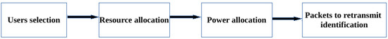
Figure 1.
Flowchart of the proposed ICIC scheme.
Real time services are sensitive to delay and packet loss. The proposed scheme aims to keep delay and packet loss under acceptable values specified by the QoS Class Identifier (QCI). According to the standardized QCI [39], the acceptable delay for conversational voice service is 100 ms while the acceptable packet loss is 1%.
In Step 1, users are selected based on user priority. The objective of the step is to minimize delay, thus packet loss. We use HoL to give priority to users given that, if a packet wait for more than acceptable delay, it will be discarded and packet loss will increase. Once users have been selected, RBs are allocated in Step 2. In Step 3, the transmit power of each enodeB on each RB is determined to maximize SINR value for each user on allocated RBs, which means minimizing intercell interference. In Step 4, packets to retransmit are identified based on the SINR value. There is no need to transmit a packet if SINR value on allocated RB is so low that it will not be recovered. The packet is then transferred to retransmission queue.
Each enodeB is responsible of RBs allocation within a cell while transmit power determination is centralized. Position of selected users is subject to changes, which makes reinforcement learning a good choice for its flexibility to topology changes [15].
We use GA [32,40] as a policy search-based reinforcement learning for both resource allocation and power control steps. GA is a method used in evolutionary algorithms (EARL) [41,42,43,44,45,46,47,48,49] for reinforcement learning as a policy search method.
Reinforcement learning is learning what to do—how to map situations to actions—to maximize a numerical reward signal [50]. A reinforcement learning system can be described by the following elements: an agent, an environment, a policy, a reward function, a value function, and, optionally, a model of the environment [50].
Genetic algorithm (GA) is an optimization and search technique based on the principles of genetics and natural selection [42,51,52]. Genetic algorithms belong to meta heuristics family approaches of solving problems and are inspired by the evolution.
5.1. User Selection Step
Users selection step is responsible for selecting users that are eligible for RBs allocation. Users selection is done per cell.
Depending on the number of users, the number of possible combinations to have for allocating resource blocks can be very high.
It does not make sense to allocate resource to users if there are no packets to be sent to them. Packets should be sent within acceptable delay, otherwise they will be discarded. The selection process then considers buffer status (transmission and retransmission queues) and head of line delay so that only users having packets to receive will be selected. Users are selected in two phases to reduce the state space for the resource allocation step.
In the first phase, users are sorted according to the buffer status. Since a resource block should be allocated to users that may effectively use it in order to not waste it, only users that have data to receive are eligible to be selected. Both transmission queues and retransmission queues are considered. Two lists are obtained. The first list contains users having data in their transmission queue and the second list contains users having data in their retransmission queue. The two lists are then combined to make one list.
In the second step, users are selected based on their priority. The HoL defines the priority. Users that have their HoL closed to the maximum allowed for the considered service are placed on the top of the list. The number of users selected is greater than the number of resource blocks available.
The selection process is summarized in Algorithm 1.
Algorithm 1 not only cares about QoS but also cares about fairness, since, if a user is starving, its head of line delay will become higher. It also cares about users with bad channel conditions since users having traffic in their retransmission buffer are considered. Users having their HoL greater than the maximum delay allowed will have some packets discarded in the frequency domain scheduler and that action will lowered their HoL.
| Algorithm 1: Users selection |
 |
5.2. Resource Allocation Step
This step is responsible for allocating resource blocks to users selected in the previous step.
In this step, policy space based reinforcement learning is used instead of value function space to allocate RBs to users selected in the previous step. Policy space search methods use explicit policies and modify them through search operators [41]. We use GA as a policy space search, where a policy is represented by a chromosome. An agent interacts with its environment and learns the best policy to allocate RBs to users. The reinforcement learning agent–environment interaction [13] for resource allocation is represented in Figure 2, where is a representation of the state at time t and represents action taken by an agent at time t, which leads to the state after receiving reward at time . represents reward received from previous action. There are two possible rewards: −1 and 1.
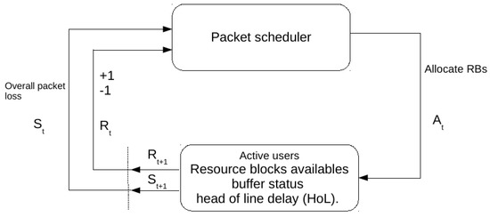
Figure 2.
Reinforcement learning agent–environment interaction for resource allocation.
The environment is composed of the following parameters: user buffer status and user head of line delay (HoL).
A state represents the number of users with their HoL, their buffer status, the overall packet loss ratio, and the QoS bearers, as in [53].
An agent is a packet scheduler located at each enodeB, thus we have a multi-agent environment. A policy is an action taken by an agent in a given state. An action chooses for each RB a user that the RB will be allocated to. For simplicity, a RB will carry one packet.
A reward is then associated on each action taken by the agent. If action taken by an agent increases the packet loss ratio, a negative reward is given to the agent. If the action taken by an agent decreases the packet loss ratio, a positive reward is given to the agent. The two reward values are −1 and +1.
A single policy represents a chromosome [41]. A good policy should have a fitness value below a given threshold corresponding to the QoS requirements of a given service. The fitness function for the resource allocation GA algorithm is the sum of HoL.
A RB represents a gene. Its value corresponds to a user that the RB have been allocated to. A chromosome is a set of available RBs that are allocated each time to interval (TTI).
Each gene will be encoded in decimal to ease the computational process. The size of the population will not vary.
Elitism strategy is used to keep the best solutions and the least feasible solutions are been discarded.
A sample chromosome is shown in Figure 3 that represents a policy used for a sub agent located in a cell with a bandwidth that have 25 RBs and 60 actives users. The numbers represent users. We can see that User 60 has been allocated two non-contiguous RBs, User 9 has been allocated two non-contiguous RBs, User 25 has been allocated two contiguous RBs, and User 16 has been allocated two non-contiguous RBs.

Figure 3.
Policy example for 25 Resource Blocks and 60 active users. The numbers inside the blocks indicate users.
The resource allocation can be modeled by a matrix where each row represents cells and each column represents a resource block to be allocated. A sample resource allocation matrix can be seen in Table 1 for a network composed of n cells and a bandwidth corresponding to m RBs where identifies cells and identifies resource blocks. For example, is the first cell and is the first resource block. represents user i in cell j. A vector is used for chromosome representation to ease GA operations crossover and mutation.

Table 1.
Resource allocation matrix.
An initial population of policies is generated at the beginning of the reinforcement learning process. An agent evaluates each policy through policy evaluation. A fitness function is used to do this.
Each policy is evaluated and improved to obtain the best policy. The best policy will be the policy that delivers packet loss ratio value less than or equal to the value of the maximum packet loss acceptable according to the QoS requirements [39]. The population of policies is modified through crossover and mutation operations over a defined number of generations with the aim of solutions converging to the best solution. This corresponds to the learning process during which policies are improved.
During crossover operation, some chromosomes are selected according to the crossover probability and divided into two groups. Pairs of chromosomes are composed by choosing one chromosome on each of the two groups to be crossed in order to produce new chromosomes. An example of crossover operation is shown in Figure 4. The number of RBs of each chromosome is 25. In this example, two chromosomes, namely Child 1 and Child 2, are obtained from two chromosomes, namely Parent 1 and Parent 2.
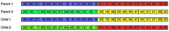
Figure 4.
Example of crossover operation.
During mutation operation, some chromosomes are selected according to the mutation probability to be mutated. Six genes are randomly chosen to be mutated on each chromosome selected for mutation to add diversity to population.
A gene value represents a user to whom the corresponding RB is allocated. Mutation of a gene consists of changing its value. In other words, mutating a gene means deallocating a RB from a user and allocating it to another user. The RB is allocated to a user in the waiting list, which contains users selected in the first step of the proposed ICIC scheme but have not been selected to form the initial population of chromosomes.
An example of mutation operation is shown in Figure 5. An initial chromosome is replaced (mutated) to obtain a mutated chromosome by changing the color of genes, which means deallocating RBs previously allocated to users associated to these genes from the initial chromosome and allocating these RBs to users in the waiting list.
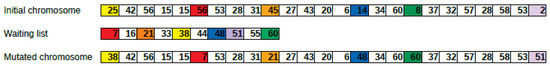
Figure 5.
Example of mutation operation.
The best policy is obtained after selection, crossover, mutation and evaluation have been repeated a certain number of generations, and then the learning process terminates.
Elitism strategy is used for chromosomes selection and the population size is kept constant. Chromosomes are sorted according to their fitness function value after crossover and mutation operations. Since crossover and mutation operations increase the population number, selection operation ignore will retain only a number of solutions equal to the number of the initial population and discard the remaining solutions. Retained solutions are chosen among the best solutions. The whole process is summarized in Algorithm 2. Details are shown in Algorithm 3. Algorithm 4 details the update of buffers and HoL as well as packet loss calculation operation in Algorithm 3.
| Algorithm 2: Resource allocation algorithm |
 |
| Algorithm 3: Resource allocation algorithm details |
 |
| Algorithm 4: Buffers and HoL update |
 |
5.3. Dynamic Power Allocation Step
An agent learns to find the best policy, which maximizes SINR values for each user on each cell. The environment of the agent is a multi-cell network composed of enodeBs and users’ geographic locations.
A state represents the location of a user and its SINR value. Only users that have been allocated at least one physical resource block are considered.
The agent is located at a centralized unit that may be located on one of the enodeBs and collects geographic location of users on each enodB. The agent learns the best policy to set transmit power for each enodeB on each physical resource block allocated to users based on their locations.
A reward is associated to each action taken by the agent. If the action taken by an agent is such that the obtained SINR is less than the minimum SINR acceptable, a negative (−1) reward is given to the agent. If the action taken by an agent is such that the obtained SINR is greater than the minimum SINR, a positive reward (+1) is given to the agent.
The reinforcement learning agent–environment interaction [13] is presented in Figure 6 where , , , and have been described in the resource allocation step.
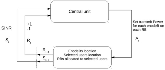
Figure 6.
Reinforcement learning agent–environment interaction of the power allocation problem.
A single policy represents a chromosome [41]. The transmit power of an enodeb on a RB represents a gene. A chromosome is a set of transmit power on each enodeB on each RB.
Each policy is evaluated by the minimum SINR obtained with the corresponding enodeB’s transmit power. A gene represents an enodeB transmit power on a RB. A chromosome sample is shown in Table 2.
Table 2.
Power allocation chromosome.
The power allocation problem can be seen as a matrix represented in Table 3 for a network composed by n cells with a bandwidth corresponding to m RBs. In Table 2 and Table 3, represents transmit power of enodeB in cell i on resource block . For example, is the transmit power of enodeBin cell 1 on the first resource block and is the transmit power of enodeBin cell 2 on the first resource block.
Table 3.
Power allocation matrix.
An initial population of policies is generated at the beginning of the learning process. Each gene in a policy is assigned randomly a transmit power value between the minimum transmit power and the maximum transmit power. An agent will evaluate each policy through policy evaluation. The minimum SINR is used as fitness function of the power allocation GA. Precisely, the range of SINR values is used as fitness function. To lower the computation process time, a SINR is calculated for each user only on RBs that have been allocated to the user. Each policy is evaluated during a process where the initial population is modified through crossover and mutation operations. A good policy is the one that has a minimum SINR value greater than the minimum acceptable SINR value. Policies evaluation is repeated many times corresponding to a number of generations in order to find the best policy. Policies are improved during policies evaluation.
Crossover operation is done similar to the one in resource allocation step. An example of crossover operation is shown in Figure 7 for a power allocation in a network that has three cells and a bandwidth of 5 MHz corresponding to 25 RBs.
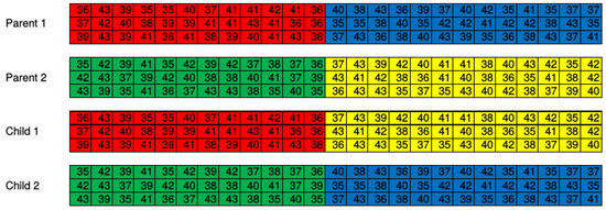
Figure 7.
Crossover operation for power allocation.
Mutation operation is done similar to the one in resource allocation step. An example of mutation operation is shown in Figure 8 for a three-cell network with 25 RBs to allocate on each cell.
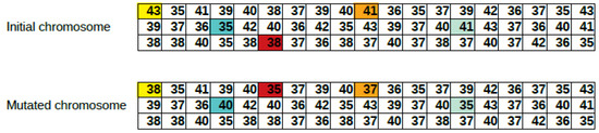
Figure 8.
Mutation operation for power allocation.
The whole process of dynamic power allocation is summarized in Algorithm 5. The algorithm has some input parameters: users coordinates in the network, maximum and minimum transmit power, population size, generations number, crossover rate, and mutation rate. Details of how initial population is generated, and evaluation and selection of policies, and crossover and mutation operations are done can be viewed in Algorithm 6.
| Algorithm 5: Power allocation summary algorithm |
 |
5.4. Packet to Retransmit Identification Step
In this step, we identify which packets to retransmit. In the previous step, transmit power of each enodeB on each RB have been set. A best solution solution may have some users still experiencing high interference by getting low SINR. We assume a packet sent on the corresponding RBs might not be correctly decoded at the receiver side and thus will be rejected. These packets should be transferred in the retransmission queue of the corresponding user. The retransmission is handled by the HARQ manager. There are eight parallel stop and wait (SAW) HARQ processes. The retransmission of packets can occur at any time relative to the initial transmission since HARQ processes are asynchronous in the LTE downlink. The step is summarized in Algorithm 7.
| Algorithm 6: Power allocation algorithm details |
 |
| Algorithm 7: Packet to retransmit identification algorithm |
 |
6. Results and Discussions
To verify the effectiveness of our ICIC scheme, a Matlab® based simulation tool was implemented.
The simulation tool enables us to change system model and genetic algorithm parameters. System model parameters that were changed are the number of cells, the bandwidth, the number of active users, and the simulation time in terms of number of TTIs. Genetic algorithm parameters that were changed are population size, selection rate, crossover rate, mutation rate and number of generations.
We conducted simulations for an LTE network with 19 cells [16] with one enodeB located on each cell; a bandwidth of 5 MHz [16], which corresponds to 25 RBs to share among users; and a simulation time of 3000 TTIs. Different number of active users were taken (50, 150, 200, 2500, 300, 350, 400, 450, 500, 550 and 600) to observe the performance of the proposed method and its overhead. Each enodeB used omnidirectional antenna. UEs were randomly distributed in each cell. Voice traffic was considered with a Poisson distribution. Each user’s transmission queue was updated with a new packet every 20 ms corresponding to inter arrival time [38]. Head of line delay and buffer size were set according to VoIP QoS requirements [39].
For the EARL parameters, we tried many combinations but, for results shown here, we used a population size of 500, a selection rate of 0.5, a crossover rate of 0.4, a mutation rate of 0.1 and a number of generations of 50. We choose maximum transmit power to 43 dBm [27] and we set minimum transmit power to 35 dBm. The range of transmit power was [35 dBm, 43 dBm] for the proposed power allocation algorithm, and 43 dBm for the uniform transmit power scenario. Note that, for uniform transmit power, Equation (1) (Section 3) was used but all transmit power values were equal to 43 dBm.
Table 4.
System model parameters.
Table 5.
GA parameters.
For each active users number, we executed 100 simulation runs. At the beginning of each simulation, each user’s position was randomly generated within a cell. Performance of proposed ICIC scheme was evaluated in terms of average packet loss ratio, delay and SINR.
6.1. Average Packet Loss Ratio
The reinforcement learning agent converges after 50 generations for each TTI. Average packet loss ratio results values were compared with values obtained with maximum throughput (MT), Proportional Fairness (PF), Earlier Deadline First (EDF) and Largest Weighted Delay First (LWDF) [54] algorithms, which results were calculated with a confidence interval of 95%, as shown in Figure 9. We implemented these algorithms as well.
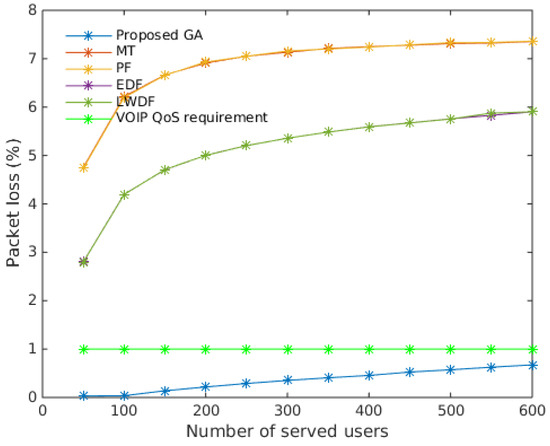
Figure 9.
Overall average packet loss with 95% confidence interval. Proposed GA showed better performances.
It can be seen from the figure that our proposed resource allocation algorithm showed the best packet error loss ratio compared to MT, PF, EDF and LWDF resource allocation algorithms. The figure shows that packet error loss ratio significantly increased with the number of served users. It is worth nothing that our proposed resource allocation algorithm is the only algorithm that gave packet error loss rate below conversational voice QoS requirement, which is 1% for packet error loss ratio [39]. The packet loss values of our proposed GA algorithm were between 0.03% and 0.67% while packet loss values of other algorithms were between 2.7% and 7.3%, which are far greater than voice QoS requirement. This difference can be explained by other algorithms using metrics that are mathematical functions and the algorithm always being able allocate resources to users that have the maximum value of corresponding metric. The advantage of the proposed GA algorithm is that it is a heuristic method.
6.2. Delay
To compare performances of proposed GA algorithm, we considered cumulative distribution of head of line delay at the end of each simulation. Figure 10 shows empirical cumulative distribution function of user’s HoL at the end of a simulation for each algorithm. We plotted the figure for a maximum active users equal to 600. Recall that HoL value is between 1 and 100 ms, such that, if a packet stays longer in the buffer, the HoL increases and, when it reaches 100 ms, the last packet is discarded.
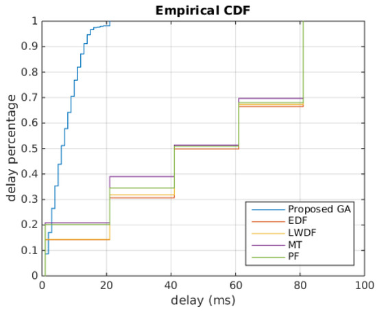
Figure 10.
Cumulative Distribution function of delay. Proposed GA showed better performances than other algorithms.
It can be seen in the figure that our proposed resource allocation algorithm showed the best delay distribution compared to MT, PF, EDF and LWDF resource allocation algorithms. The Figure shows that, at the end of the simulation, HoL value of our proposed GA were between 0 ms and 20 ms, while HoL values of other algorithms were between 0 ms and 80 ms. We can see that 50% of users had HoL values between 0 ms and 40 ms and 50% of users had HoL values between 40 ms and 80 ms, which means HoL values of other algorithms tended to reach maximum HoL value leading to packets being discarded. This confirm results in shown in Figure 9.
6.3. SINR
Figure 11 presents performance of the proposed ICIC scheme in term of SINR. The figure also shows performance of RF1, SFR, fuzzy logic system [27] and uniform transmit power schemes for comparison. We chose to present SINR performance as cumulative distributions that show the range in which SINR values belong. Recall that SINR is calculated according to Equation (1) (Section 3). The thermal noise was −174 dBm. We drew the cumulative distribution functions of SINR for these methods from results shown in [27].
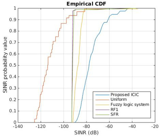
Figure 11.
Cumulative Distribution function of SINR. Proposed ICIC scheme was clearly suboptimal.
The figure clearly shows that our proposed ICIC scheme performed better than the other ICIC schemes with SINR values in the range [−90, −40]. Fuzzy logic system scheme followed with most SINR values in the range [−90, −80]. Fuzzy logic system outperformed RF1 and SFR, which had SINR values in the range [−90, −87]. However, SFR had better performance than RF1. Uniform transmit power scheme had the worst performance among the all of the schemes.
RF1, SFR and Fuzzy logic system have in common the partitioning of the bandwidth, which has a disadvantage. A user may not be allocated a resource block because there is no resource block available in its area, while at the same time a resource block may be unused in another area. This will negatively impact the performance of the network in terms of packet loss.
7. Conclusions
In this paper, an intercell interference coordination scheme for downlink LTE networks that aims to minimize intercell interference is proposed. The proposed scheme combines resource allocation and dynamic power control using genetic algorithm as policy space search reinforcement learning.
Simulations results show the effectiveness of our proposed ICIC scheme. The proposed resource allocation algorithm gives more than seven times less packet loss ratio and delay performance compared to maximum throughput (MT), Proportional Fairness (PF), Earlier Deadline First (EDF) and Largest Weighted Delay First (LWDF).
Our proposed power allocation scheme effectively minimizes intercell interference by increasing SINR compared to RF1, SFR, fuzzy logic system [27] and uniform transmit power schemes.
The next steps for future research direction would be to use real data from real LTE networks to learn solutions offline through exploration process and to use results obtained for online exploitation.
Author Contributions
Conceptualization, D.T. and K.; Methodology, A.F.; Software, D.T.; Validation, D.T., A.F., K. and S.D.Y.; Formal Analysis, D.T.; Investigation, D.T.; Resources, D.T.; Data Curation, D.T.; Writing—Original Draft Preparation, D.T.; Writing—Review and Editing, A.F.; and Supervision, K. and S.D.Y.
Funding
Djorwe Temoa has been partially supported by Erasmus Mobility Program Key Action 107 between Germany and Cameroon.
Conflicts of Interest
The authors declare no conflict of interest.
References
- Holma, H.; Toskala, A. LTE for UMTS: Evolution to LTE-Advanced; John Wiley & Sons: Hoboken, NJ, USA, 2011. [Google Scholar]
- Yassin, M.; AboulHassan, M.A.; Lahoud, S.; Ibrahim, M.; Mezher, D.; Cousin, B.; Sourour, E.A. Survey of ICIC techniques in LTE networks under various mobile environment parameters. Wirel. Netw. 2017, 23, 403–418. [Google Scholar] [CrossRef]
- Dahlman, E.; Parkvall, S.; Skold, J.; Beming, P. 3G Evolution: HSPA and LTE for Mobile Broadband; Academic Press: Cambridge, MA, USA, 2010. [Google Scholar]
- 3GPP. TR 25.814, Radio Access Network, Physical layer aspects for evolved Universal Terrestrial Radio Access (UTRA) (Release 7) v7.1.0. Etsi 2006, 1–132. [Google Scholar]
- Lescuyer, P.; Lucidarme, T. Evolved Packet System (EPS): The LTE and SAE Evolution of 3G UMTS; John Wiley & Sons: Hoboken, NJ, USA, 2008. [Google Scholar]
- Hassan, N.U.; Assaad, M. Optimal fractional frequency reuse (FFR) and resource allocation in multiuser OFDMA system. In Proceedings of the International Conference on Information and Communication Technologies, ICICT’09, Karachi, Pakistan, 15–16 August 2009; pp. 88–92. [Google Scholar]
- Mao, X.; Maaref, A.; Teo, K.H. Adaptive Soft Frequency Reuse for Inter-Cell Interference Coordination in SC-FDMA Based 3GPP LTE Uplinks. In Proceedings of the GLOBECOM, New Orleans, LA, USA, 30 November–4 December 2008; pp. 4782–4787. [Google Scholar]
- Sternad, M.; Ottosson, T.; Ahlén, A.; Svensson, A. Attaining both coverage and high spectral efficiency with adaptive OFDM downlinks. In Proceedings of the 58th IEEE Vehicular Technology Conference, VTC 2003-Fall, Orlando, FL, USA, 6–9 October 2003; Volume 4, pp. 2486–2490. [Google Scholar]
- Rahman, M.; Yanikomeroglu, H.; Wong, W. Interference avoidance with dynamic inter-cell coordination for downlink LTE system. In Proceedings of the Wireless Communications and Networking Conference, WCNC 2009, Budapest, Hungary, 5–8 April 2009; pp. 1–6. [Google Scholar]
- Priscoli, F.D.; Magnani, N.P.; Palestini, V.; Sestini, F. Application of dynamic channel allocation strategies to the GSM cellular network. IEEE J. Sel. Areas Commun. 1997, 15, 1558–1567. [Google Scholar] [CrossRef]
- Krasniqi, B.; Wrulich, M.; Mecklenbrauker, C.F. Network-load dependent partial frequency reuse for LTE. In Proceedings of the 9th International Symposium on Communications and Information Technology, ISCIT 2009, Icheon, Korea, 28–30 September 2009; pp. 672–676. [Google Scholar]
- Sawahashi, M.; Kishiyama, Y.; Morimoto, A.; Nishikawa, D.; Tanno, M. Coordinated multipoint transmission/reception techniques for LTE-advanced [Coordinated and Distributed MIMO]. IEEE Wirel. Commun. 2010, 17. [Google Scholar] [CrossRef]
- Sutton, R.S.; Barto, A.G. Reinforcement Learning: An Introduction; MIT Press: Cambridge, MA, USA, 2018. [Google Scholar]
- Förster, A.; Udugama, A.; Görg, C.; Kuladinithi, K.; Timm-Giel, A.; Cama-Pinto, A. A novel data dissemination model for organic data flows. In Proceedings of the International Conference on Mobile Networks and Management, Santander, Spain, 16–18 September 2015; pp. 239–252. [Google Scholar]
- Kulkarni, R.V.; Forster, A.; Venayagamoorthy, G.K. Computational intelligence in wireless sensor networks: A survey. IEEE Commun. Surv. Tutor. 2011, 13, 68–96. [Google Scholar] [CrossRef]
- Daeinabi, A.; Sandrasegaran, K.; Zhu, X. Survey of intercell interference mitigation techniques in LTE downlink networks. In Proceedings of the 2012 IEEE Australasian Telecommunication Networks and Applications Conference (ATNAC), Brisbane, QLD, Australia, 7–9 November 2012; pp. 1–6. [Google Scholar]
- Soret, B.; Pedersen, K.I.; Jørgensen, N.T.; Fernández-López, V. Interference coordination for dense wireless networks. IEEE Commun. Mag. 2015, 53, 102–109. [Google Scholar] [CrossRef]
- Hamza, A.S.; Khalifa, S.S.; Hamza, H.S.; Elsayed, K. A survey on inter-cell interference coordination techniques in OFDMA-based cellular networks. IEEE Commun. Surv. Tutor. 2013, 15, 1642–1670. [Google Scholar] [CrossRef]
- Kwan, R.; Leung, C. A survey of scheduling and interference mitigation in LTE. J. Electr. Comput. Eng. 2010, 2010, 1. [Google Scholar] [CrossRef]
- Aboulhassan, M.A.; Yassin, M.; Lahoud, S.; Ibrahim, M.; Mezher, D.; Cousin, B.; Sourour, E.A. Classification and comparative analysis of inter-cell interference coordination techniques in LTE networks. In Proceedings of the 2015 7th International Conference on New Technologies, Mobility and Security—NTMS 2015 Conference and Workshops, Paris, France, 27–29 July 2015. [Google Scholar]
- Kim, J.; Karim, N.A.; Cho, S. An Interference Mitigation Scheme of Device-to-Device Communications for Sensor Networks Underlying LTE-A. Sensors 2017, 17, 1088. [Google Scholar]
- Katsinis, G.; Tsiropoulou, E.E.; Papavassiliou, S. Multicell Interference Management in Device to Device Underlay Cellular Networks. Future Internet 2017, 9, 44. [Google Scholar] [CrossRef]
- Kim, W.C.; Paek, M.J.; Ro, J.H.; Song, H.K. Adaptive CoMP with Spatial Phase Coding for Interference Mitigation in the Heterogeneous Network. Appl. Sci. 2018, 8, 631. [Google Scholar] [CrossRef]
- Fan, X.; Chen, S.; Zhang, X. An inter-cell interference coordination technique based on users’ ratio and multi-level frequency allocations. In Proceedings of the International Conference on Wireless Communications, Networking and Mobile Computing, WiCom 2007, Shanghai, China, 21–25 September 2007; pp. 799–802. [Google Scholar]
- Rahman, M.; Yanikomeroglu, H. Enhancing cell-edge performance: A downlink dynamic interference avoidance scheme with inter-cell coordination. IEEE Trans. Wirel. Commun. 2010, 9, 1414–1425. [Google Scholar] [CrossRef]
- Al-Rawi, M.; Jantti, R.; Torsner, J.; Sagfors, M. Channel-aware inter-cell interference coordination for the uplink of 3G LTE networks. In Proceedings of the Wireless Telecommunications Symposium, WTS 2009, Prague, Czech Republic, 22–24 April 2009; pp. 1–5. [Google Scholar]
- Daeinabi, A.; Sandrasegaran, K.; Zhu, X. An intercell interference coordination scheme in LTE downlink networks based on user priority and fuzzy logic system. Int. J. Wirel. Mob. Netw. 2013, 5, 49. [Google Scholar] [CrossRef]
- Yassin, M.; Lahoud, S.; Ibrahim, M.; Khawam, K.; Mezher, D.; Cousin, B. Non-Cooperative Inter-Cell Interference Coordination Technique for Increasing Throughput Fairness in LTE Networks. In Proceedings of the 2015 IEEE 81st Vehicular Technology Conference (VTC Spring), Glasgow, Scotland, 11–14 May 2015; pp. 1–5. [Google Scholar]
- Poulkov, V.; Koleva, P.; Asenov, O.; Iliev, G. Combined power and inter-cell interference control for LTE based on role game approach. Telecommun. Syst. 2014, 55, 481–489. [Google Scholar] [CrossRef]
- Essassi, S.; Cherif, S.; Siala, M. RB allocation based on genetic algorithm and coordination over the X 2 interface in the LTE uplink. In Proceedings of the IEEE International Symposium on Personal, Indoor and Mobile Radio Communications, PIMRC, London, UK, 8–11 September 2013; pp. 2424–2428. [Google Scholar]
- Shahid, A.; Aslam, S.; Kim, H.S.; Lee, K.G. Genetic algorithm based self-organized resource allocation in LTE-Advanced network. In Proceedings of the 2014 Sixth International Conference on Ubiquitous and Future Networks (ICUFN), Shanghai, China, 8–11 July 2014; pp. 133–137. [Google Scholar]
- Sivanandam, S.; Deepa, S. Genetic algorithm optimization problems. In Introduction to Genetic Algorithms; Springer: Berlin, Germany, 2008; pp. 165–209. [Google Scholar]
- Dorigo, M.; Birattari, M. Ant colony optimization. In Encyclopedia of Machine Learning; Springer: Berlin, Germany, 2011; pp. 36–39. [Google Scholar]
- Blum, C.; Li, X. Swarm intelligence in optimization. In Swarm Intelligence; Springer: Berlin, Germany, 2008; pp. 43–85. [Google Scholar]
- Van Laarhoven, P.J.; Aarts, E.H. Simulated annealing. In Simulated Annealing: Theory and Applications; Springer: Berlin, Germany, 1987; pp. 7–15. [Google Scholar]
- Quinlan, J.R. Induction of decision trees. Mach. Learn. 1986, 1, 81–106. [Google Scholar] [CrossRef]
- Sesia, S.; Baker, M.; Toufik, I. LTE-the UMTS Long Term Evolution: From Theory to Practice; John Wiley & Sons: Hoboken, NJ, USA, 2011. [Google Scholar]
- Poikselkä, M.; Holma, H.; Hongisto, J.; Kallio, J.; Toskala, A. Voice over LTE: VoLTE; John Wiley & Sons: Hoboken, NJ, USA, 2012. [Google Scholar]
- 3GPP. TS 23.203 Policy and Charging Control Architecture 2012. Available online: http://www.qtc.jp/3GPP/Specs/23203-a70.pdf (accessed on 15 January 2019).
- Randy, L.H.; Sue, E.H. Practical Genetic Algorithms; John Wiley and Sons: Hoboken, NJ, USA, 2004; p. 261. [Google Scholar]
- Moriarty, D.E.; Schultz, A.C.; Grefenstette, J.J. Evolutionary algorithms for reinforcement learning. J. Artif. Intell. Res. 1999, 11, 241–276. [Google Scholar] [CrossRef]
- Glickman, M.G.; Sycara, K. Evolutionary search, stochastic policies with memory, and reinforcement learning with hidden state. In Proceedings of the Eighteenth International Conference on Machine Learning, Williamstown, MA, USA, 28 June–1 July 2001. [Google Scholar]
- Wiering, M.; Van Otterlo, M. Reinforcement learning. Adapt. Learn. Optim. 2012, 12, 51. [Google Scholar]
- Castillo, C.; Lurgi, M.; Martinez, I. Chimps: An evolutionary reinforcement learning approach for soccer agents. In Proceedings of the IEEE International Conference on Systems, Man and Cybernetics, Washington, DC, USA, 5–8 October 2003; Volume 1, pp. 60–65. [Google Scholar]
- Siebel, N.T.; Sommer, G. Evolutionary reinforcement learning of artificial neural networks. Int. J. Hybrid Intell. Syst. 2007, 4, 171–183. [Google Scholar] [CrossRef]
- Liu, F.; Zeng, G. Study of genetic algorithm with reinforcement learning to solve the TSP. Expert Syst. Appl. 2009, 36, 6995–7001. [Google Scholar] [CrossRef]
- Kim, G.H.; Lee, C.G. Genetic reinforcement learning approach to the heterogeneous machine scheduling problem. IEEE Trans. Robot. Autom. 1998, 14, 879–893. [Google Scholar]
- Metzen, J.H.; Edgington, M.; Kassahun, Y.; Kirchner, F. Analysis of an evolutionary reinforcement learning method in a multiagent domain. In Proceedings of the 7th International Joint Conference on Autonomous Agents and Multiagent Systems, Estoril, Portugal, 12–16 May 2008; Volume 1, pp. 291–298. [Google Scholar]
- Chen, G.; Zelinka, I. Evolutionary Algorithms, Swarm Dynamics and Complex Networks; Springer: Berlin, Germany, 2018. [Google Scholar]
- Sutton, R.S.; Barto, A.G. Reinforcement learning. Learning 2012, 3, 322. [Google Scholar] [CrossRef]
- Goldberg, D.E. Genetic algorithms in search, optimization, and machine learning; Addison-Wesley Professional: Boston, MA, USA, 1989. [Google Scholar]
- Haupt, R.L.; Haupt, S.E.; Haupt, S.E. Practical Genetic Algorithms; Wiley: New York, NY, USA, 1998; Volume 2. [Google Scholar]
- Comşa, I.S.; Aydin, M.; Zhang, S.; Kuonen, P.; Wagen, J.F. Reinforcement learning based radio resource scheduling in LTE-advanced. In Proceedings of the 2011 17th IEEE International Conference on Automation and Computing (ICAC), Karlsruhe, Germany, 14–18 June 2011; pp. 219–224. [Google Scholar]
- Capozzi, F.; Piro, G.; Grieco, L.A.; Boggia, G.; Camarda, P. Downlink packet scheduling in LTE cellular networks: Key design issues and a survey. IEEE Commun. Surv. Tutor. 2013, 15, 678–700. [Google Scholar] [CrossRef]
© 2019 by the authors. Licensee MDPI, Basel, Switzerland. This article is an open access article distributed under the terms and conditions of the Creative Commons Attribution (CC BY) license (http://creativecommons.org/licenses/by/4.0/).