
Study on Mechanical Properties of Steel-Strengthened Bamboo Beams with Webbing Opening

Abstract
1. Introduction
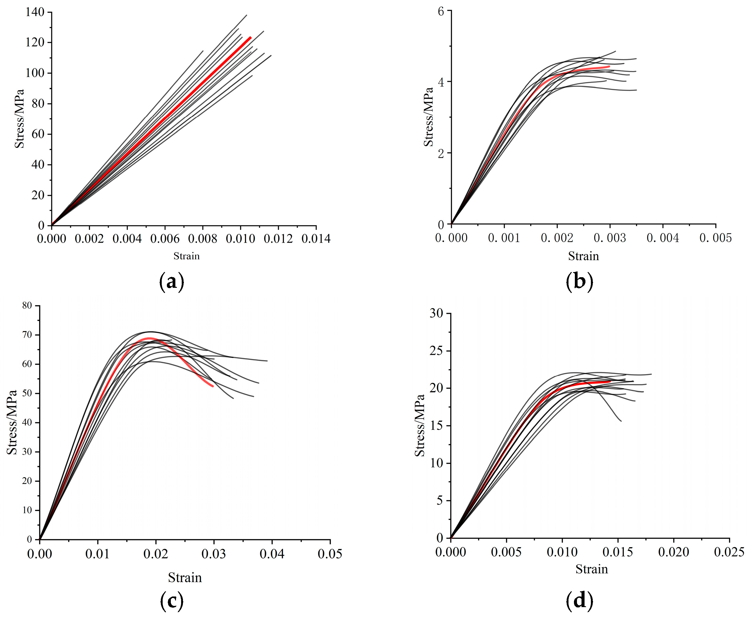
2. Material Properties and Manufacturing
2.1. Steel Sections
2.2. Structural Adhesives
3. Overview of the Experiment
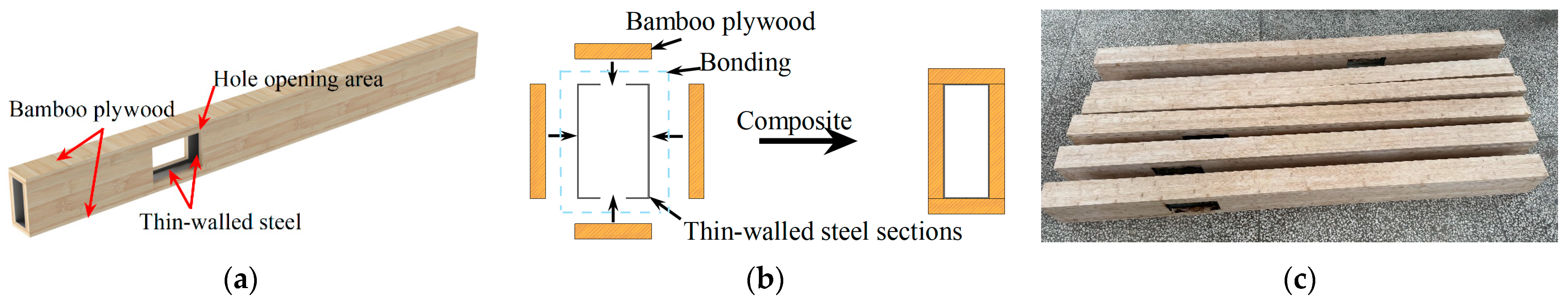
3.1. Specimen Design and Fabrication
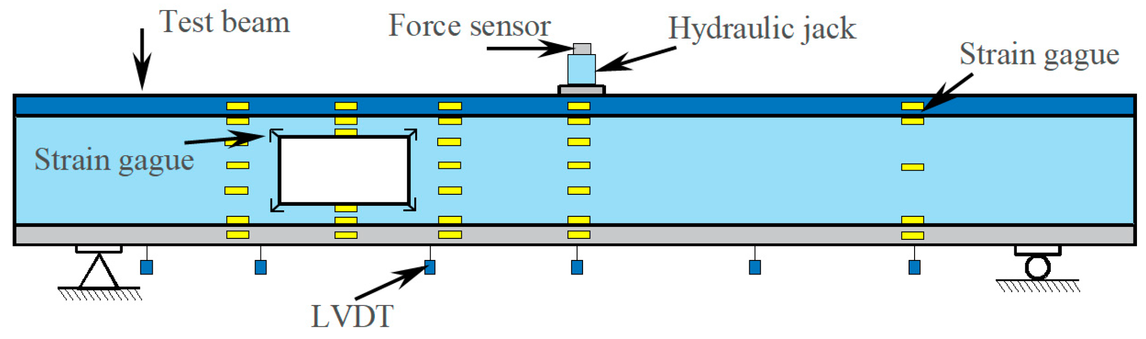
3.2. Loading Device and Measurement Point Arrangement
4. Test Results and Analyses
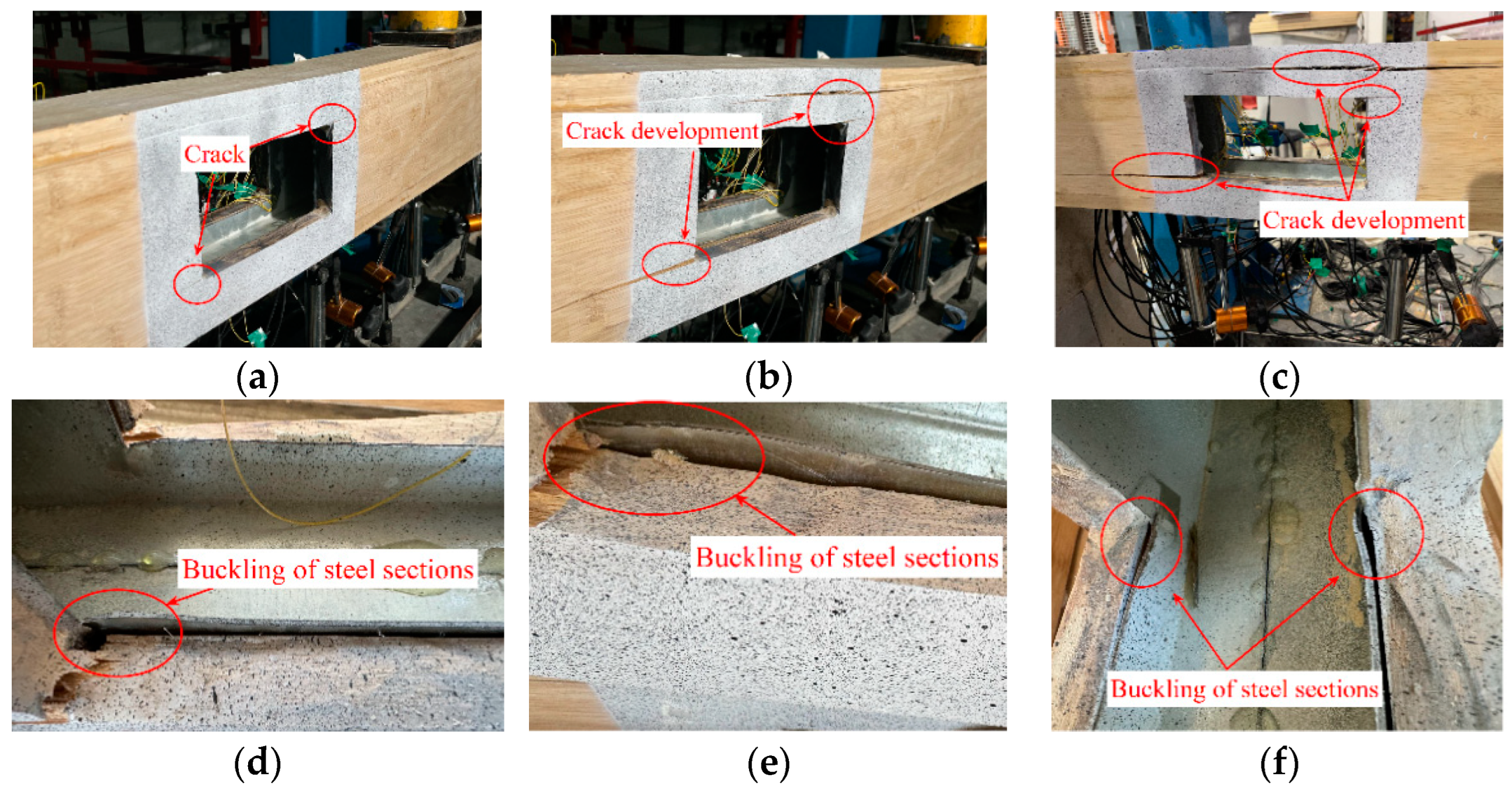
4.1. Destruction Characteristics
4.2. Load–Deflection Curve
4.3. Parametric Studies
4.3.1. Effect of Hole Location
4.3.2. Effect of Hole Size
4.3.3. Effect of Bamboo Web Thickness
4.3.4. Influence of the Thickness of Thin-Walled Steel Sections
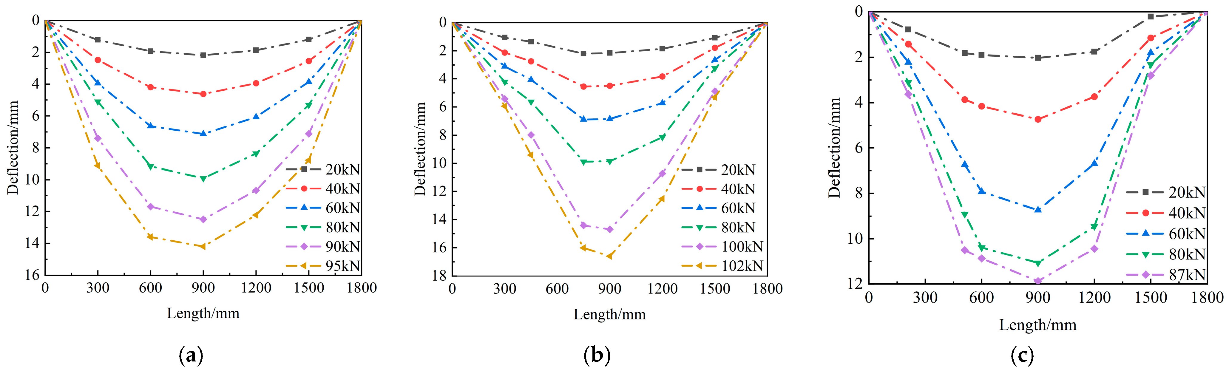
4.4. Deflection Distribution Along the Beam Length
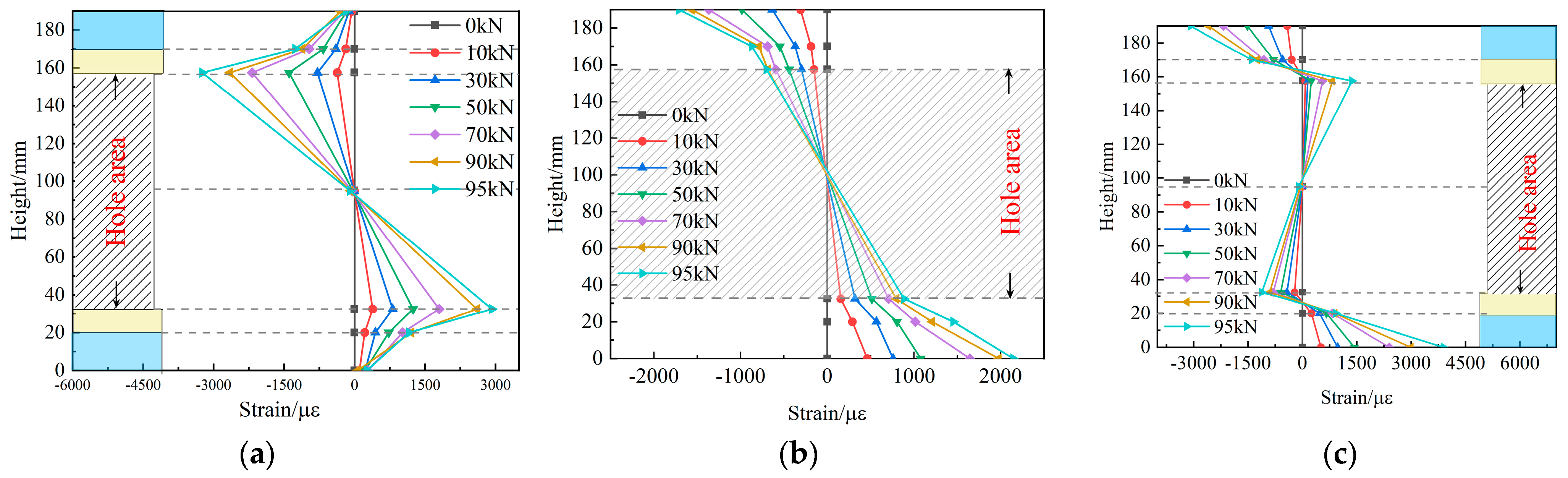
4.5. Strain Distribution in the Hole Section
5. Finite Element Analysis
5.1. Mechanical Properties of Materials
5.1.1. Steel Sections
5.1.2. Bamboo Plywood
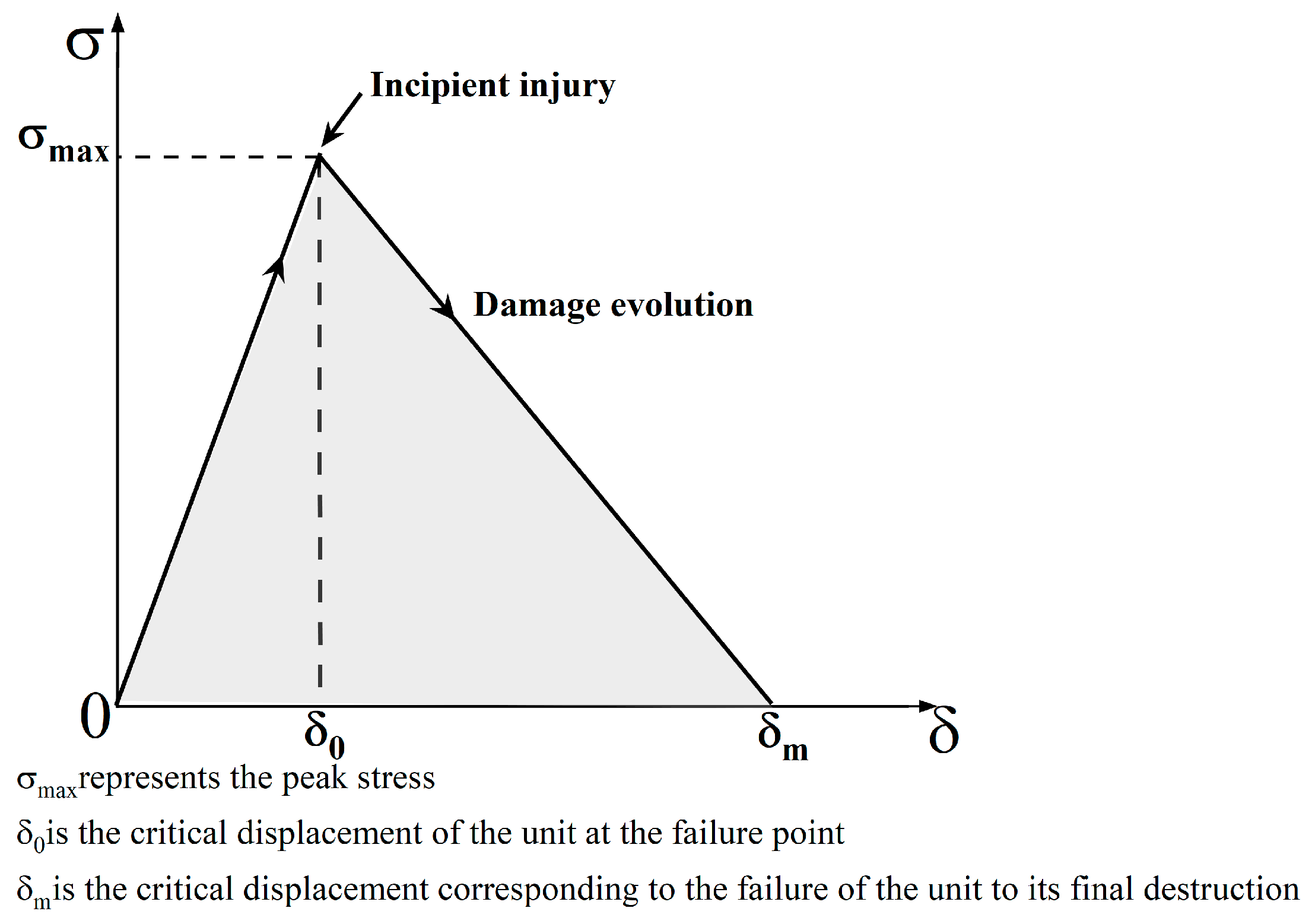
5.1.3. Structural Adhesive
5.2. Cell Types and Meshing
5.3. Comparison Between Test Results and Finite Element Results
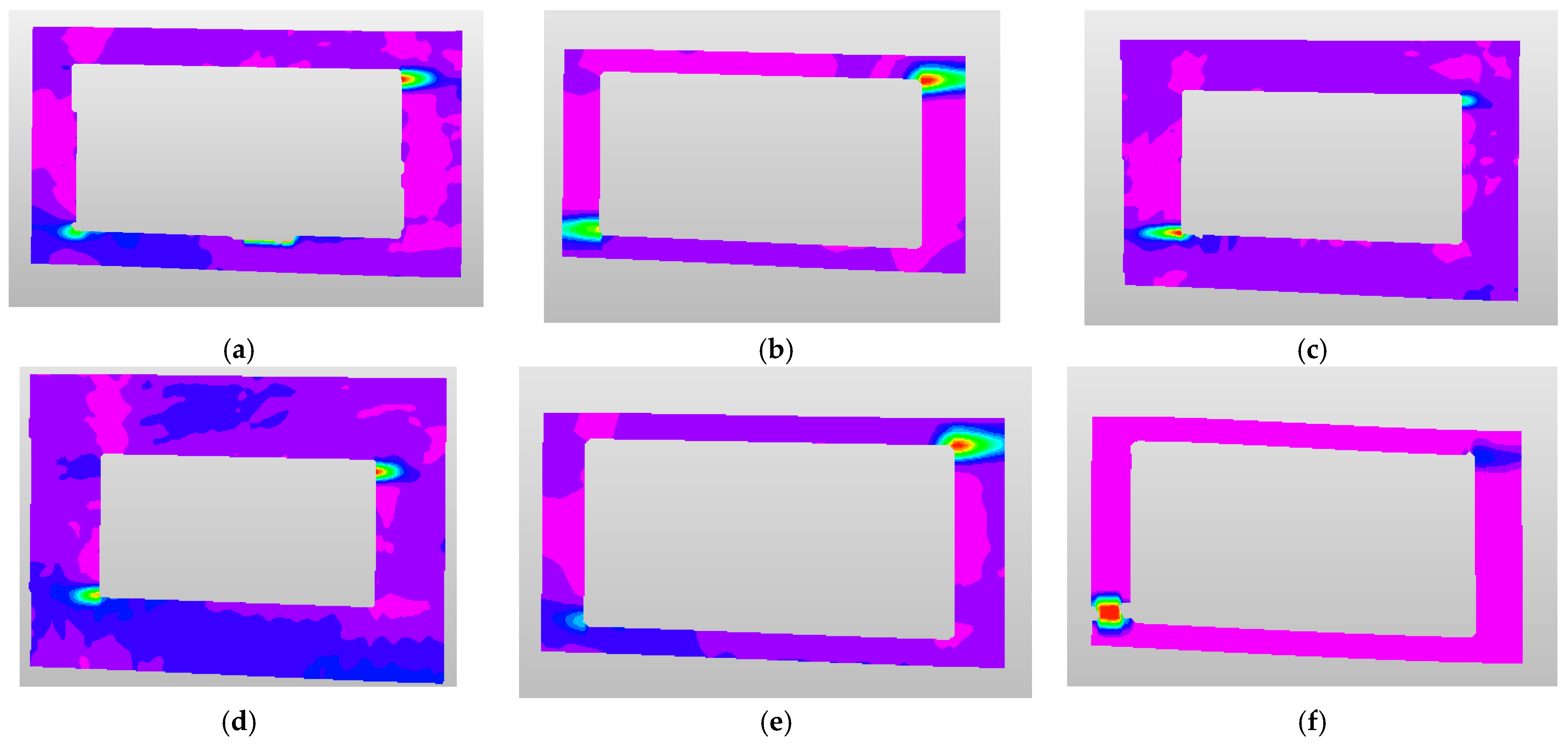
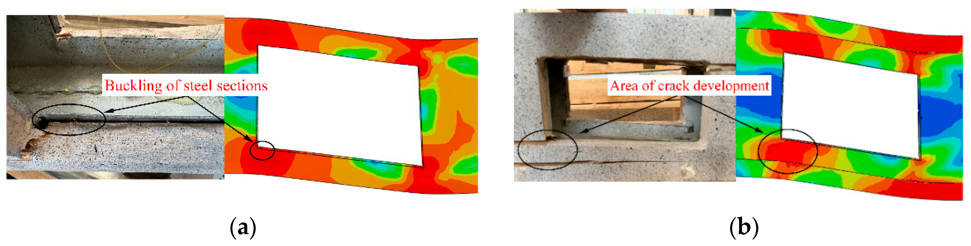
5.3.1. Comparison of Damage Characteristics
5.3.2. Comparison of Load–Deflection Curves
5.4. Basic Parameters of Finite Element Analysis
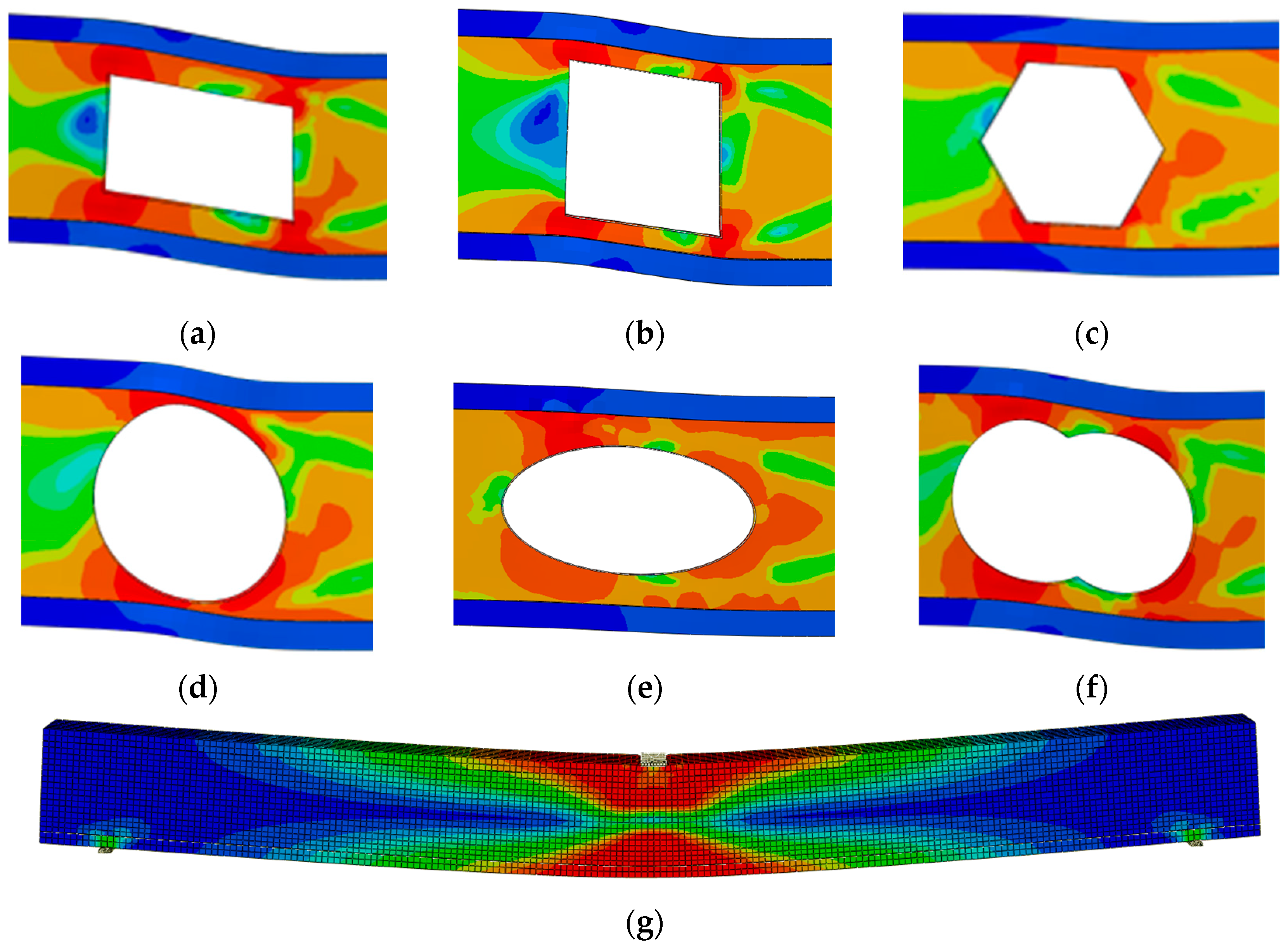
5.5. Analysis of Simulation Results
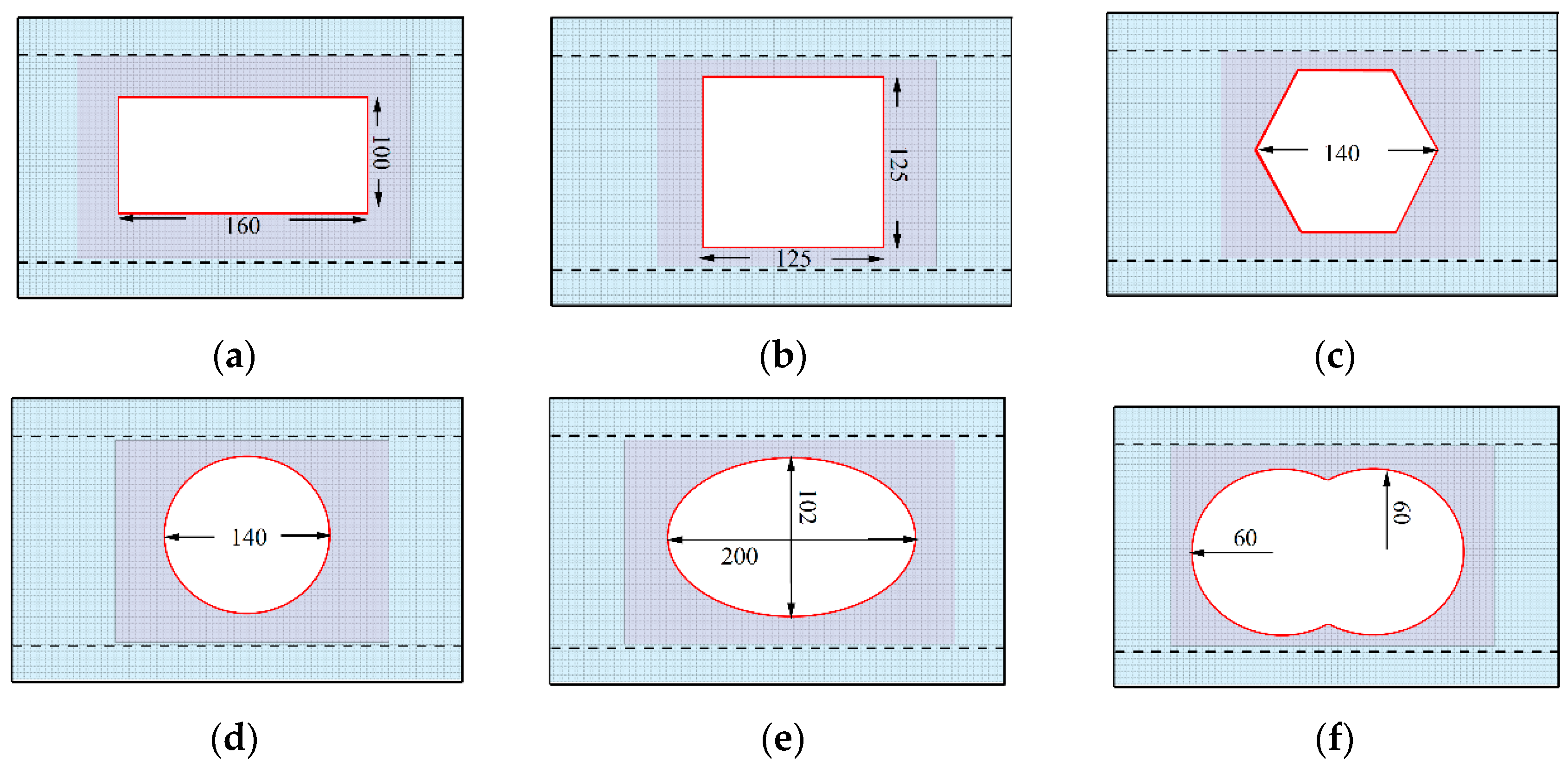
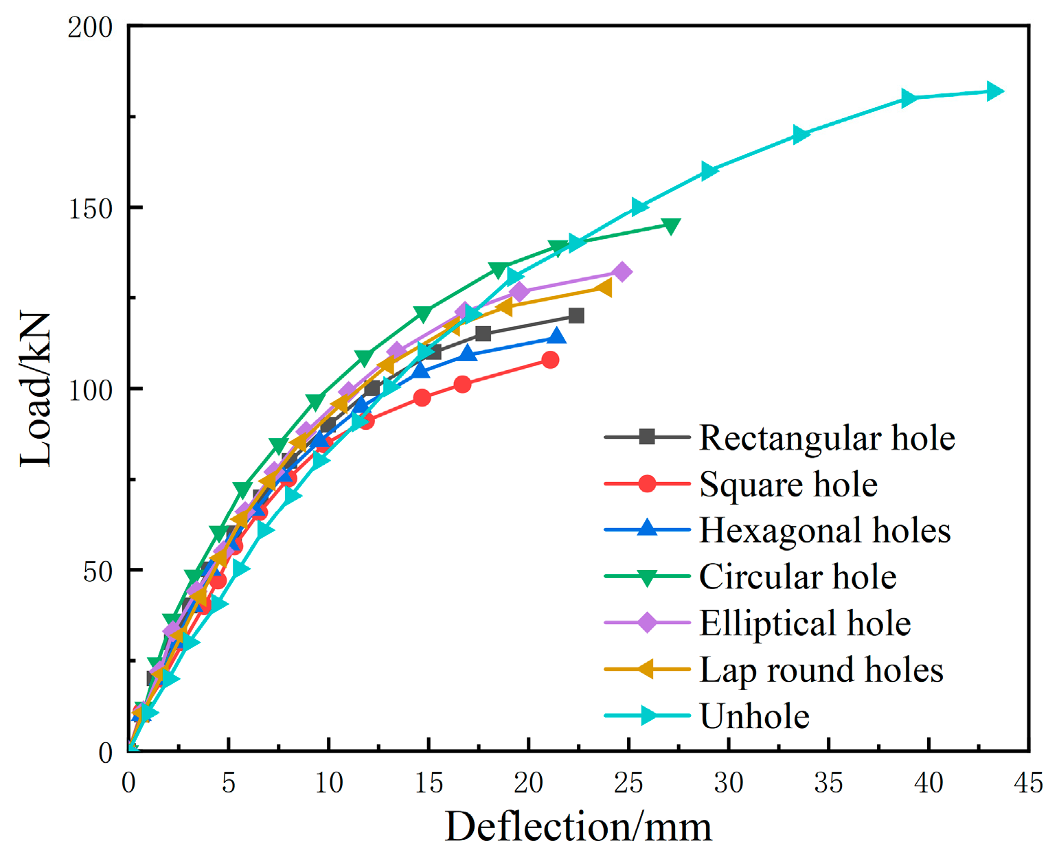
Load–Deflection Curves
6. Conclusions
Author Contributions
Funding
Data Availability Statement
Conflicts of Interest
References
- Chaowana, P. Bamboo: An Alternative Raw Material for Wood and Wood-Based Composites. J. Mater. Sci. Res. 2013, 2, 90. [Google Scholar] [CrossRef]
- Liu, D.; Song, J.; Anderson, D.P.; Chang, P.R.; Hua, Y. Bamboo Fiber and Its Reinforced Composites: Structure and Properties. Cellulose 2012, 19, 1449–1480. [Google Scholar] [CrossRef]
- Guo, J.; Tang, J.; Wen, Y.; Zhang, J.; Li, Y. Development status of modern bamboo structure building. Appl. Mech. Mater. 2013, 351, 26–29. [Google Scholar] [CrossRef]
- Sharma, B.; Gatoo, A.; Bock, M.; Mulligan, H.; Ramage, M. Engineered Bamboo: State of the Art. Proc. Inst. Civ. Eng. Constr. Mater. 2015, 168, 57–67. [Google Scholar] [CrossRef]
- Huang, Y.; Qi, Y.; Zhang, Y.; Yu, W. Progress of bamboo recombination technology in China. Adv. Polym. Technol. 2019, 1, 2723191. [Google Scholar] [CrossRef]
- Sharma, B.; Gatóo, A.; Bock, M.; Ramage, M. Engineered Bamboo for Structural Applications. Constr. Build. Mater. 2015, 81, 66–73. [Google Scholar] [CrossRef]
- Chung, K.F.; Lawson, R.M. Simplified Design of Composite Beams with Large Web Openings to Eurocode 4. J. Constr. Steel Res. 2001, 57, 135–164. [Google Scholar] [CrossRef]
- Chung, K.F.; Liu, C.H.; Ko, A.C.H. Steel Beams with Large Web Openings of Various Shapes and Sizes: An Empirical Design Method Using a Generalised Moment-Shear Interaction Curve. J. Constr. Steel Res. 2003, 59, 1177–1200. [Google Scholar] [CrossRef]
- Liu, T.C.H.; Chung, K.F. Steel Beams with Large Web Openings of Various Shapes and Sizes: Finite Element Investigation. J. Constr. Steel Res. 2003, 59, 1159–1176. [Google Scholar] [CrossRef]
- Wang, P.; Zhou, D.; Wang, Y. Experimental study on shear capacity of steel-concrete beams with open web. Eng. Mech. 2013, 30, 297–305. [Google Scholar] [CrossRef]
- Wang, P.; Zhou, D.; Wang, Y. Theoretical study on ultimate bearing capacity of combined beams with stiffened rib webs and open holes. Eng. Mech. 2013, 30, 138–146. [Google Scholar] [CrossRef]
- Du, H.; Hu, C.; Shi, D. Effect of reinforcement on the strength of the web opening in steel-concrete composite beam. Eng. Struct. 2021, 235, 112038. [Google Scholar] [CrossRef]
- Borri, A.; Corradi, M.; Speranzini, E. Reinforcement of Wood with Natural Fibers. Compos. Part B Eng. 2013, 53, 1–8. [Google Scholar] [CrossRef]
- Mcconnell, E.; Mcpolin, D.; Taylor, S. Post-tensioning of glulam timber with steel tendons. Constr. Build. Mater. 2014, 73, 426–433. [Google Scholar] [CrossRef]
- Vahedian, A.; Shrestha, R.; Crews, K. Experimental and Analytical Investigation on CFRP Strengthened Glulam Laminated Timber Beams: Full-Scale Experiments. Compos. Part B Eng. 2019, 164, 377–389. [Google Scholar] [CrossRef]
- Schober, K.U.; Harte, A.M.; Kliger, R.; Jockwer, R.; Xu, Q.; Chen, J. FRP reinforcement of timber structures. Constr. Build. Mater. 2015, 97, 106–118. [Google Scholar] [CrossRef]
- Rescalvo, F.; Valverde-Palacios, I.; Suarez, E.; Gallego, A. Experimental Comparison of Different Carbon Fiber Composites in Reinforcement Layouts for Wooden Beams of Historical Buildings. Materials 2017, 10, 1113. [Google Scholar] [CrossRef]
- Gómez, E.P.; González, M.N.; Hosokawa, K.; Cobo, A. Experimental Study of the Flexural Behavior of Timber Beams Reinforced with Different Kinds of FRP and Metallic Fibers. Compos. Struct. 2019, 213, 308–316. [Google Scholar] [CrossRef]
- Franke, S.; Franke, B.; Harte, A.M. Failure Modes and Reinforcement Techniques for Timber Beams–State of the Art. Constr. Build. Mater. 2015, 97, 2–13. [Google Scholar] [CrossRef]
- Zhang, J.; Tong, K.; Wu, P.; Li, Y. Research Status on Steel-bamboo Composite Structure. MATEC Web Conf. 2019, 275, 01018. [Google Scholar] [CrossRef]
- Shen, H.Y.; Li, Y.S.; Zhang, Z.W.; Jiang, T.Y.; Liu, J. Application and prospect of bamboo/steel composite material in civil engineering structure. Adv. Mater. Res. 2010, 113, 989–993. [Google Scholar] [CrossRef]
- Li, Y.; Shen, H.; Shan, W.; Han, T. Flexural Behavior of Lightweight Bamboo–Steel Composite Slabs. Thin-Walled Struct. 2012, 53, 83–90. [Google Scholar] [CrossRef]
- Li, Y.; Yao, J.; Li, R.; Zhang, Z.; Zhang, J. Thermal and Energy Performance of a Steel-Bamboo Composite Wall Structure. Energy Build. 2017, 156, 225–237. [Google Scholar] [CrossRef]
- Zhang, X.; Xu, J.; Zhang, X.; Li, Y. Life cycle carbon emission reduction potential of a new steel-bamboo composite frame structure for residential houses. J. Build. Eng. 2021, 39, 102295. [Google Scholar] [CrossRef]
- Li, Y.; Shan, W.; Shen, H.; Zhang, Z.-W.; Liu, J. Bending Resistance of I-Section Bamboo–Steel Composite Beams Utilizing Adhesive Bonding. Thin-Walled Struct. 2015, 89, 17–24. [Google Scholar] [CrossRef]
- Liu, H.; Wei, Y.; Huang, L.; Chen, S.; Lin, Y. Shear Behaviour of I-Shaped Steel with Bamboo Scrimber Composite Beams. Arch. Civ. Mech. Eng. 2023, 24, 3. [Google Scholar] [CrossRef]
- Yang, X.; Sun, C.; Huo, F.; Gong, Y.; Sun, Y. Shear Property and Uniform Vertical Load Capacity of Bamboo I-Beams. Forests 2022, 13, 826. [Google Scholar] [CrossRef]
- Ding, J.; Wang, X.; Ge, Y.; Zhang, Z.; Li, Y. Experimental Study and Theoretical Analysis of the Shear Behavior of Single-Box Double-Chamber Steel-Bamboo Composite Beams. Eng. Struct. 2023, 296, 116959. [Google Scholar] [CrossRef]
- Ding, J.; Wang, X.; Ge, Y.; Zhang, J.; Shan, Q.; Xu, S.; Wang, J.; Li, Y. Experimental and Nonlinear Analytical Investigation of the Flexural Performance of Single-Box Double-Chamber Steel–Bamboo Composite Beams. Thin-Walled Struct. 2023, 183, 110424. [Google Scholar] [CrossRef]
- GB/T 1927.14-2022; Test Methods for Physical and Mechanical Properties of Small Clear Woodspecimens-Part 14: Determination of Tensile Strength Parallel to Grain. Standards Press of China: Beijing, China, 2022.
- GB/T 1927.11-2022; Test Methods for Physical and Mechanical Properties of Small Clear Woodspecimens-Part 11: Determination of Ultimate Stress Incompression Parallel to Grain. Standards Press of China: Beijing, China, 2022.
- GB/T 228.1-2010; Metallic Materials-Tensile Testing-Part 1: Method of Test at Room Temperature. Standards Press of China: Beijing, China, 2010.
- GB 50005-2017; Standard for Design of Timber Structures. Standards Press of China: Beijing, China, 2017.
- Xu, D.; Li, Y.; Zhang, Z. Application of cohesion model in the deformation analysis of steel-bamboo composite beams. For. Ind. 2018, 45, 42–47. [Google Scholar] [CrossRef]


| EX/MPa | EY/MPa | EZ/MPa | VX | VY | VZ | GX/MPa | GY/MPa | GZ/MPa |
|---|---|---|---|---|---|---|---|---|
| 5240.5(123) (0.234) | 630.7(29.05) (0.046) | 630.7(29.05) (0.046) | 0.213(0.007) (0.032) | 0.213(0.007) (0.032) | 0.115(0.01) (0.086) | 1190(70.65) (0.059) | 1190(70.65) (0.059) | 347(30.22) (0.087) |
| Specimen Thickness | Yield Strength fy/MPa | Tensile Strength fu/MPa | Modulus of Elasticity Es/MPa | Poisson’s Ratio μ |
|---|---|---|---|---|
| 1.5 mm | 247.25 (3.17) (0.012) | 306.75 (7.54) (0.024) | 2.03 × 10⁵ MPa | 0.3 |
| 2 mm | 316.84 (2.95) (0.009) | 338.33 (6.57) (0.019) | 2.05 × 10⁵ MPa | 0.3 |
| Specimen Number | L/mm | Hole Size/mm | hfb/mm | tfb /mm | tws/mm | bzy /mm | tzy/mm | Hole Location |
|---|---|---|---|---|---|---|---|---|
| L-1 | 2000 | 125 × 200 | 150 | 20 | 1.5 | 100 | 20 | 1/4 |
| L-2 | 2000 | 125 × 200 | 150 | 20 | 1.5 | 100 | 20 | 1/5 |
| L-3 | 2000 | 125 × 200 | 150 | 20 | 1.5 | 100 | 20 | 1/3 |
| L-4 | 2000 | 100 × 160 | 150 | 20 | 1.5 | 100 | 20 | 1/4 |
| L-5 | 2000 | 125 × 200 | 150 | 15 | 1.5 | 90 | 20 | 1/4 |
| L-6 | 2000 | 125 × 200 | 150 | 20 | 2 | 100 | 20 | 1/4 |
| Specimen Number | Normal Service Limit Mid-Span Deflection | Normal Use Ultimate Load Capacity | Ultimate Load Test Value | Ultimate Load Mid-Span Deflection | Ultimate Load Test Value/Normal Use Ultimate Load Capacity |
|---|---|---|---|---|---|
| L-1 | 7.2 | 70 | 95 | 14.2 | 1.35 |
| L-2 | 7.2 | 65 | 102 | 16.6 | 1.56 |
| L-3 | 7.2 | 68 | 87 | 11.8 | 1.27 |
| L-4 | 7.2 | 78 | 130 | 22.0 | 1.66 |
| L-5 | 7.2 | 67 | 81 | 11.6 | 1.20 |
| L-6 | 7.2 | 67 | 104 | 15.4 | 1.55 |
| R11 | R22 | R33 | R12 | R13 | R23 |
|---|---|---|---|---|---|
| 0.744 | 0.313 | 0.313 | 0.25 | 0.25 | 0.05 |
| E /MPa | G1 /MPa | G2 /MPa | σnmax /MPa | τsmax /MPa | τtmax /MPa | GN /(J·mm−2) | GS /(J·mm−2) | GT /(J·mm−2) |
|---|---|---|---|---|---|---|---|---|
| 1500 | 1500 | 1500 | 13.6 | 13.7 | 13.7 | 0.32 | 0.41 | 0.41 |
| Specimen Number | Hole Shape | Ultimate Carrying Capacity | Ultimate Deflection |
|---|---|---|---|
| A1 | rectangular | 120.14 | 22.41 |
| A2 | square | 107.92 | 20.78 |
| A3 | regular hexagon | 114.44 | 21.10 |
| A4 | circular | 145.41 | 27.11 |
| A5 | elliptical | 132.13 | 24.75 |
| A6 | lapped circle, | 127.77 | 23.88 |
| A7 | unhole | 182.23 | 43.21 |
Disclaimer/Publisher’s Note: The statements, opinions and data contained in all publications are solely those of the individual author(s) and contributor(s) and not of MDPI and/or the editor(s). MDPI and/or the editor(s) disclaim responsibility for any injury to people or property resulting from any ideas, methods, instructions or products referred to in the content. |
© 2024 by the authors. Licensee MDPI, Basel, Switzerland. This article is an open access article distributed under the terms and conditions of the Creative Commons Attribution (CC BY) license (https://creativecommons.org/licenses/by/4.0/).
Share and Cite
Liu, B.; Liao, W.; Zhang, T.; Yu, Y.; Dai, B.; Liu, D.; Chen, S.; Li, B. Study on Mechanical Properties of Steel-Strengthened Bamboo Beams with Webbing Opening. Forests 2024, 15, 1787. https://doi.org/10.3390/f15101787
Liu B, Liao W, Zhang T, Yu Y, Dai B, Liu D, Chen S, Li B. Study on Mechanical Properties of Steel-Strengthened Bamboo Beams with Webbing Opening. Forests. 2024; 15(10):1787. https://doi.org/10.3390/f15101787
Chicago/Turabian StyleLiu, Binhao, Wenyuan Liao, Tianyu Zhang, Yue Yu, Bihui Dai, Dewen Liu, Shaozhi Chen, and Bingjin Li. 2024. "Study on Mechanical Properties of Steel-Strengthened Bamboo Beams with Webbing Opening" Forests 15, no. 10: 1787. https://doi.org/10.3390/f15101787
APA StyleLiu, B., Liao, W., Zhang, T., Yu, Y., Dai, B., Liu, D., Chen, S., & Li, B. (2024). Study on Mechanical Properties of Steel-Strengthened Bamboo Beams with Webbing Opening. Forests, 15(10), 1787. https://doi.org/10.3390/f15101787