Article

An Estimation Model of the Ultimate Shear Strength of Root-Permeated Soil, Fully Considering Interface Bonding

1
Key Laboratory of Mountain Hazards and Earth Surface Process, Institute of Mountain Hazards and Environment, Chinese Academy of Sciences, Chengdu 610041, China
2
University of Chinese Academy of Sciences, Beijing 100049, China
*
Author to whom correspondence should be addressed.
Forests 2023, 14(4), 819; https://doi.org/10.3390/f14040819
Submission received: 14 February 2023 / Revised: 11 April 2023 / Accepted: 13 April 2023 / Published: 17 April 2023
(This article belongs to the Section Forest Soil)

Abstract

:
Roots can be seen as natural soil reinforcement material. The prediction and quantitative evaluation of the shear strength of root-permeated soil is the focus of vegetation slope protection, in which the bonding effect of the root–soil interface is the key factor. Taking the roots of Chinese fir trees as an example, the shear resistance test of root–soil interface bonding strength and the direct shear test of root-permeated soil with different root area ratios and inclination angles were carried out. The results indicated that the bonding strength of the root–soil interface could be quantified by interfacial cohesion and friction angle. The shear strength of root-permeated soil increased with the root area ratio, and its relationship with the inclination angle of root relative shear direction was: 45° > 90°. In addition, an estimation model of the ultimate shear strength of root-permeated soil was developed, in which the bonding effect of the root–soil interface was quantified by the interface bonding strength parameters. The soil stress, root diameter, root length, and the initial angle between the root and shear direction can be considered in the estimation model. The rationality and accuracy of the estimated model were verified through the comparison of experimental results and Wu’s model. The proposed model can be used to calculate the stability of the biotechnical reinforcement landslides and evaluate the shear strength of the root-permeated soil.

1. Introduction

In recent years, due to the impact of climate change, seismic disturbance and human engineering construction, soil erosion, landslides and other disasters frequently occur, which not only cause huge property losses but also seriously threaten the safety of life [1,2]. At the same time, it aggravates the degradation of the ecological environment and leads to an imbalance of the ecological environment. Plenty of studies have shown that the interaction of high modulus and strength plant roots with low modulus and strength soil improves the shear strength and deformation resistance of soil [3,4,5,6]. On the other hand, vegetation can effectively reduce the erosion of surface runoff on slope soil and soil pore water pressure by interception, evapotranspiration and infiltration [7,8,9,10] so as to stabilize soil and improve slope stability. Therefore, vegetation slope protection technology has been widely concerned and applied by many scholars and relevant departments [11,12,13,14,15]. However, the existing roots mechanical reinforcement theory lags behind the use of technology, which is insufficient to guide the implementation of vegetation slope protection technology and evaluate the stability of vegetation slope to a certain extent [16]. In addition, the mechanical reinforcement effect of roots on soil is controlled by multiple factors with spatiotemporal variabilities, such as the number of roots passing through the potential shear surface [17,18], the angle between roots and shear surface [19], root diameters and root lengths [20], the mechanical characteristics of roots [21,22], soil type, confining pressure, and soil moisture [23], and the bonding (include both friction and cohesion) of root–soil interfaces [24]. These influencing factors show significant differences under many external conditions, for example, vegetation species [25,26], fiber strength [27,28], site environment [29], climatic characteristics [30], and groundwater. Consequently, it is of great research value and practical guiding significance to identify the interaction of the root–soil and quantify the mechanical reinforcement of plant roots on soil for the prevention and control of shallow landslides, soil erosion and other geological disasters.
To quantitatively evaluate the mechanical reinforcement of plant roots, a large number of scholars have conducted relevant studies on root–soil interaction and proposed mechanical models that can partially quantitatively calculate the shear strength of root-permeated soil. Wu et al. [31] established a calculation model based on Coulomb theory to evaluate the ultimate contribution of plant roots to soil shear strength (Wu’s model), which is widely used to evaluate the reinforcement of plant roots on soil in different scenarios due to its simple parameters and strong applicability. However, it is assumed that the tensile properties of all roots can be fully exploited, and the roots break at the moment of reaching the maximum tensile strength, which makes the model significantly overestimate the contribution of roots to soil shear strength [32,33,34]. In order to more reasonably evaluate the root’s mechanical reinforcement for soil, researchers have established new theoretical models or carried out modification research of Wu’s model from different entry points, such as the fiber bundle model considering dynamic fracture of roots [34,35], fiber reinforced model based on the tensile force-displacement relationship of roots [36], the modified bundle model considering the root system displacement [37], shear strength model of root-permeated soil based on roots shear displacement and deformation [32], energy-based fiber bundle model considering both force and displacement drivers implicitly [38], and fiber bundle model considering the probabilistic distribution of root failure [39]. These models have further studied the root–soil interaction mechanism and considered the force transmission mechanism between roots and soil to some extent. For example, the conceptual parameters of interface bonding were introduced into the displacement-based model, whereas the analysis of the interface bonding effect and parameter determination is lacking. Moreover, due to the complexity of input parameters, they are less used in engineering practice or realized in numerical calculation. In addition, the current research on the improvement of Wu’s model mainly focuses on exploring the model correction coefficients of different plant types and correcting the parameters [40] in the model considering the deformation of roots [41,42], without fully considering the bonding effect between roots and soil interfaces. However, the prerequisite for the roots to play a role in soil mechanical reinforcement is the root–soil interface bonding [32,41,43]. The stress can be transferred between soil and root through the bonding effect of the root–soil interface so as to form the overall shear strength of root-permeated soil. Therefore, the bonding characteristics of the root–soil interface are an important factor affecting the macroscopic properties of root-permeated soil. The quantification of the bonding effect of the root–soil interface is the key to quantitatively evaluating the root mechanical reinforcement.
In this paper, after giving the details about the background of the present shear strength of root-permeated soil quantitative model, we presented experimental methods and results of laboratory exploration on the shear strength of root-permeated soil and analyzed the bond strength of root–soil interface and the shear strength of root-permeated soil. Next, this paper modified the current quantitative model by fully considering the bond effect between the root–soil interface and established an estimation model of the ultimate shear strength of root-permeated soil. Then, the calculated values of the estimation model were compared with the measured values of the direct shear test and the calculated values of Wu’s model, which verified the rationality and advancement of the estimation model. Lastly, the calculation parameters and limitations of the estimation model were discussed.

2. Theoretical Background of Rooted-Permeated Soil

Numerous research shows that the Coulomb shear strength formula for soils was applicable to root-permeated soil, and the existence of roots provided an additional strength for soils (Equation (1)).
τ r s = c + Δ τ r + σ tan φ
where τ r s is the shear strength of the root-permeated soil (kPa); c is the cohesion of soil (kPa); Δ τ r is roots reinforcement to soil (kPa); φ is the internal friction angle of soil (°); σ is the normal stress on the shear surface (kPa).
Based on this, researchers analyzed the additional strength of the soil provided by the roots in different ways and then developed the quantitative model of the shear strength of root-permeated soil. At present, quantitative models are mainly divided into the following three categories:

2.1. Wu’s Model

Wu et al. [31] assumed that the root tensile force in root-permeated soil could be decomposed into the tangential component of the parallel shear plane and the normal component of the vertical shear plane (Figure 1), where the tangential component increased the apparent cohesion of soil and the normal component increased the friction force of shear plane, and the formula for mechanical reinforcement was given by using Coulomb’s law (Equation (2), modified from Wu et al. [31]), namely Wu’s Model. This model has fewer parameters and is suitable for different plant roots, which is widely used by scholars to evaluate the reinforcement effect of plant roots on soil [33,44,45,46]. However, the model assumes that the tensile properties of all roots can be fully exerted and fracture at the same time when the maximum tensile strength is reached, which makes the model significantly overestimate the contribution of roots to the shear strength of the soil. This phenomenon is pointed out in subsequent studies [47,48,49].
Δ τ r w = i = 1 n t f i A r i A s ( sin θ i + cos θ i tan φ ) = 1.2 i = 1 n t f i A r i A s
where n is the number of roots crossing the shear surface of the soil; t f i is the tensile strength of the i-th root (kPa); A r i is the cross-sectional area of the i-th root (m2); A s is the shear area of soil (m2); θ i is the angle between the i-th root and the normal direction of the shear surface after deformation (°); φ is the internal friction angle of soil (°). Wu et al. [31] found that sin θ i + cos θ i tan φ was not sensitive to the changes of θ and φ in the range of 40–70° and 25–40°, respectively, and the values range from 0.92 to 1.31. Therefore, the constant 1.2 was used to replace sin θ i + cos θ i tan φ in practice.

2.2. Fiber Bundle Model

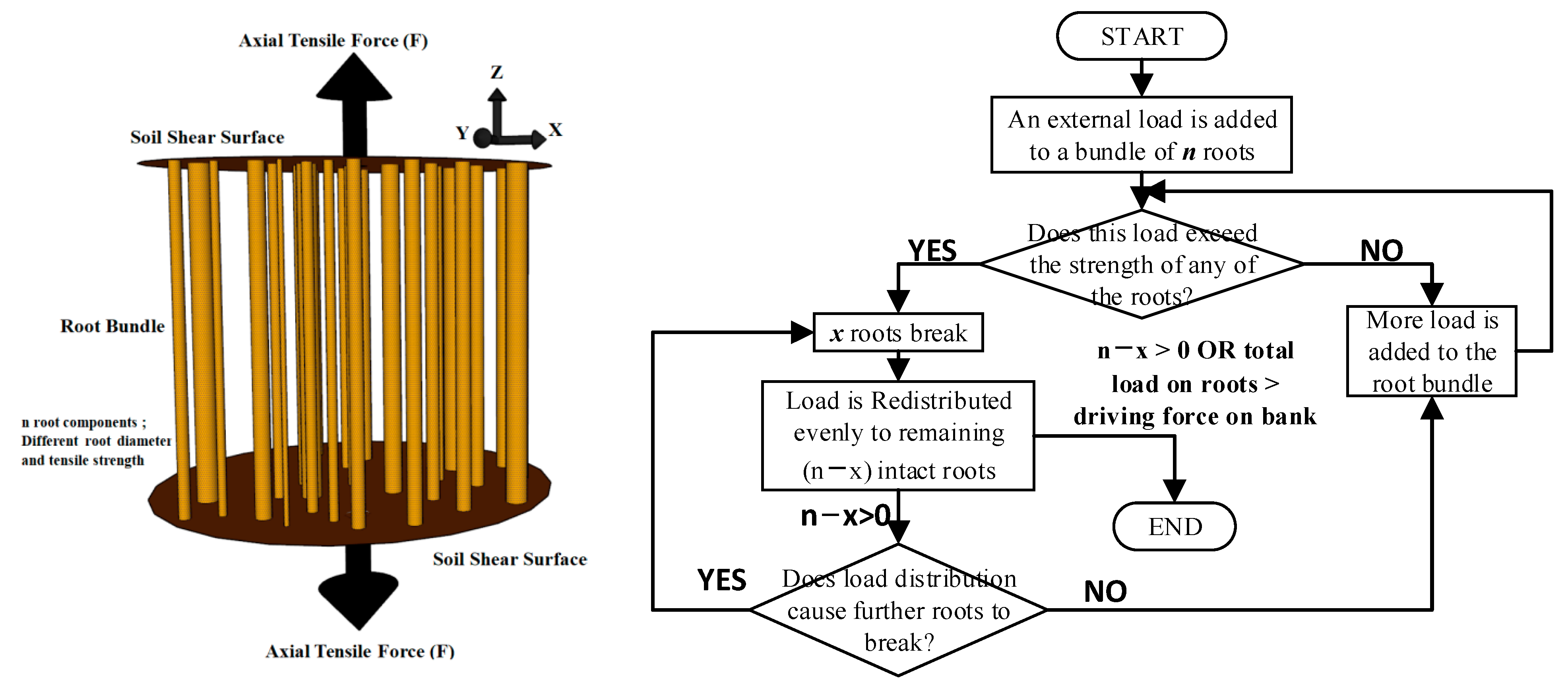
Pollen and Simon [34] proposed a fiber bundle model (Figure 2) based on stress redistribution, considering the dynamic movement of roots’ tensile force and progressive fracture of roots during the deformation process of root-permeated soil. Schwarz et al. [36] developed a fiber-reinforced model that controlled the loading process by displacement by establishing the relationship between tensile force and tensile displacement of roots (Equation (3)). However, the fiber bundle model assumes that the driving force of the soil and the stress of the broken root from the newly distributed stress were all transferred to the roots in root-permeated soil and ignores the important root–soil interaction. It is suitable for the case that the driving force is mainly axial force, such as the instability of river embankment, the sliding of the back edge of a slope sliding mass, etc.
F t o t ( Δ x ) Δ x = i = 1 N F i ( Δ x f ) n i i = 1 N F i ( Δ x 0 ) n i
where F t o t ( Δ x ) is the total tensile force of root bundle and a function of displacement Δ x (N); F i ( Δ x ) is the tensile force of roots belonging to diameter class i (N); N is the number of diameter classes; n is the number of roots present in the bundle of diameter class i; Δ x f and Δ x 0 are the tensile displacements at two different loads.

2.3. Displacement-Based Model

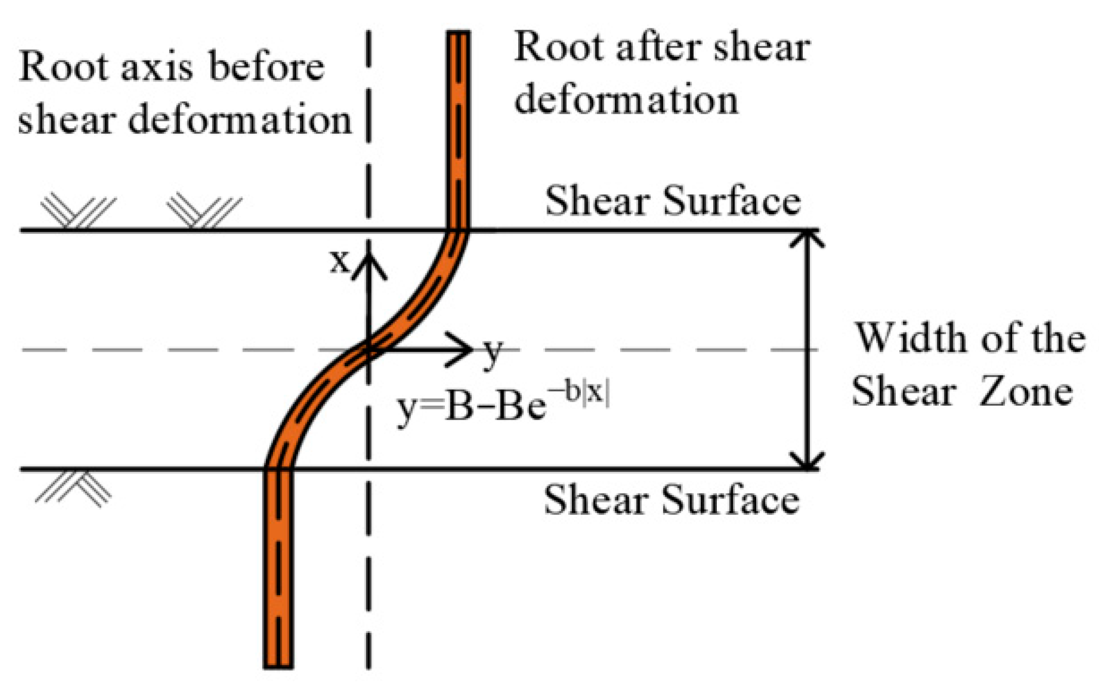
Abe et al. [50] and Fan et al. [32] established a displacement-based model (Equation (4)) for estimating the shear resistance of root-permeated soils considering the deformation characteristics of roots in the shear zone (Figure 3). The accuracy of displacement-based model calculation depends on the accurate fitting of the root deformation function in root-permeated soil. However, it is difficult to accurately observe the root deformation in in situ tests or laboratory tests. In addition, the parameters of the model are complex and difficult to obtain, so it is rarely used to evaluate the strength of root-permeated soil under different application scenarios.
{ Δ S = E I b 3 B A + ( sin θ + cos θ tan φ ) A r A t r t r = { { ( 1 + B 2 b 2 e 2 b x ) 1 / 2 1 } E , { ( 1 + B 2 b 2 e 2 b x ) 1 / 2 1 } E < { t f 2 τ r s i L r D r } min t f , L r > t f D r / 2 τ r s i & { ( 1 + B 2 b 2 e 2 b x ) 1 / 2 1 } E > t f 2 τ r s i L r / D r , L r < t f D r / 2 τ r s i & { ( 1 + B 2 b 2 e 2 b x ) 1 / 2 1 } E > 2 τ r s i L r / D r
where Δ S is the shear resistance contributed by the root system for a given shear deformation, E is the elastic modulus of the root (MPa); I denotes the rotational inertia of the root section (kg. m2); B represents half of the shear displacement of soil (m); b is the deformation attenuation constant for measuring root deformation in the shear zone; t r is the tensile stress of root; L r denotes the root length under the shear surface (m); D r is the root diameter (m); τ r s i is the bond strength between the root–soil interface (kPa).
This research shows that several models are available to estimate the shear strength of rooted-permeated soil. They mainly considered the failure mode and deformation of roots; however, the analysis of the bonding effect of the root–soil interface was insufficient. Although the displacement-based model added the bond parameters of the root–soil interface, the determination of bond strength of the root–soil interface was also pointed out by the author in the research limitations. In addition, with the deepening of the research on the root–soil interaction, the calculation accuracy of the quantitative model of root mechanical reinforcement is also greatly improved, whereas the model parameters are complex and difficult to obtain, so it is rarely applied in practical engineering and numerical calculation. Therefore, from the perspective of the model application, it is necessary to establish an estimation model of the shear strength of root-permeated soil with simple parameters and strong applicability. Based on the mechanical mechanism of root reinforcement, the bond strength between the root and soil interface should be fully considered in the model.

3. Experiments Method

3.1. Materials

(1)
Overview of the Study Area
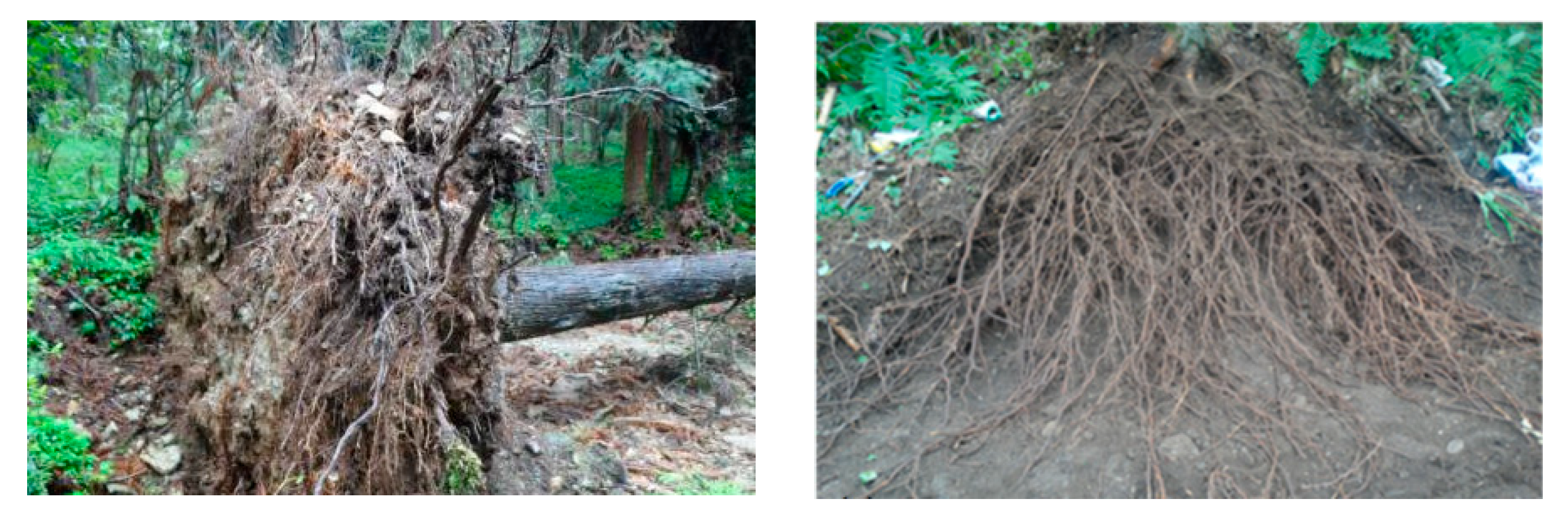
The selected study area was located in Longchi National Forest Park (103°11′38″–103°52′16″ E, 31°4′40″–31°17′37″ N, altitude 520–3280 m) in the Longxi River Basin at the junction of the Western Sichuan Plain and the Qinghai-Tibet Plateau. The study area belongs to the subtropical monsoon climate zone. The annual distribution of rainfall is very uneven, concentrated from May to September, with heavy rainfall intensity and high frequency. During the rainy season, geological disasters, such as collapse, landslides and debris flow and soil erosion, often occur in the region [51]. Chinese fir is typical vegetation in the study area, which plays a very important role in soil and water conservation and climate regulation [52]. In addition, the main root development of Chinese fir is not obvious, and horizontal scattered roots are more developed (Figure 4). Therefore, the lateral roots of Chinese fir trees in the study area were taken as the research object of the model verification test.
(2)
Plant roots
The location and characteristics of the Chinese fir tree sampled from the roots are shown in Table 1. The collected roots were stored in a refrigerator at 4° time. Considering the size limitation of the shear box in the indoor direct shear test, we selected roots with uniform root diameter, good growth and a diameter of 2 mm ± 0.1 mm as the root material used in the verification test. Because the water content has a great influence on the mechanical properties of roots, to reduce experimental error by root water content, the collected and stored roots are carried out under the same environmental conditions.
(3)
Soil material
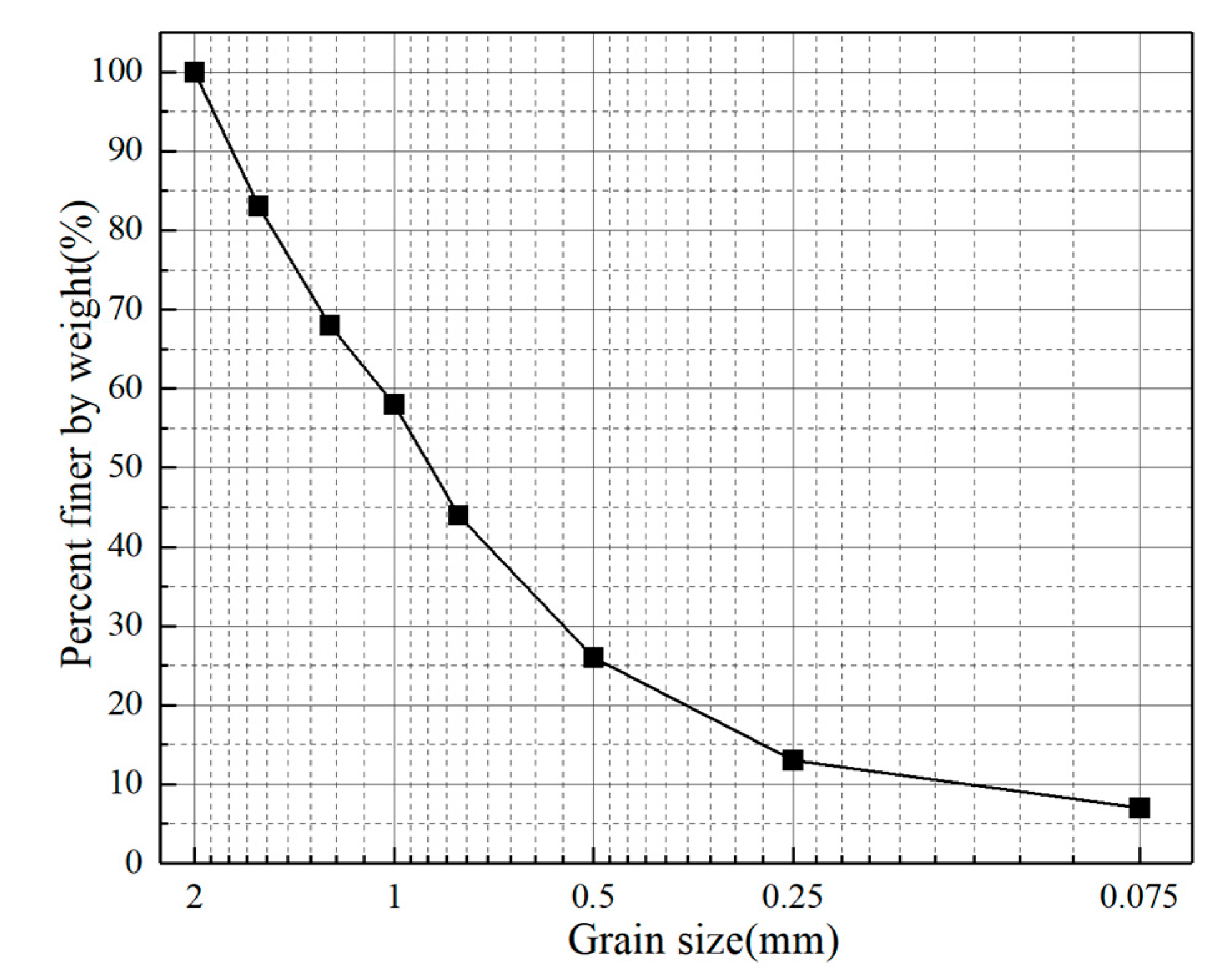
To eliminate the influence of plant humus, the soil below 30 cm in the surface layer at the root sampling site of Chinese fir was selected as the experimental soil material, with a water content of 22% and a dry density of 1.11 g/cm−3. Fine particle content of soil accounted for 7.5%. The plastic limit and liquid limit of particle size less than 0.5 mm were 7.08 and 28.68, respectively. The collected soil samples were dried at 105° ± 5° for 24 h, and then the maximum particle size was controlled to be 2 mm for screening to obtain the dry soil required for the test. According to the measured water content of the soil in the study area, the required water content of the test soil was calculated. The dry soil was graded and gradually mixed with water to ensure a uniform mixing of water and soil. After full stirring, the soil was transferred into the sealed fresh-keeping bag for one night to obtain the test soil with a water content of 22%. The grain-size frequent curve of the test soil is shown in Figure 5.

3.2. Scheme and Procedure

(1)
Root tensile test
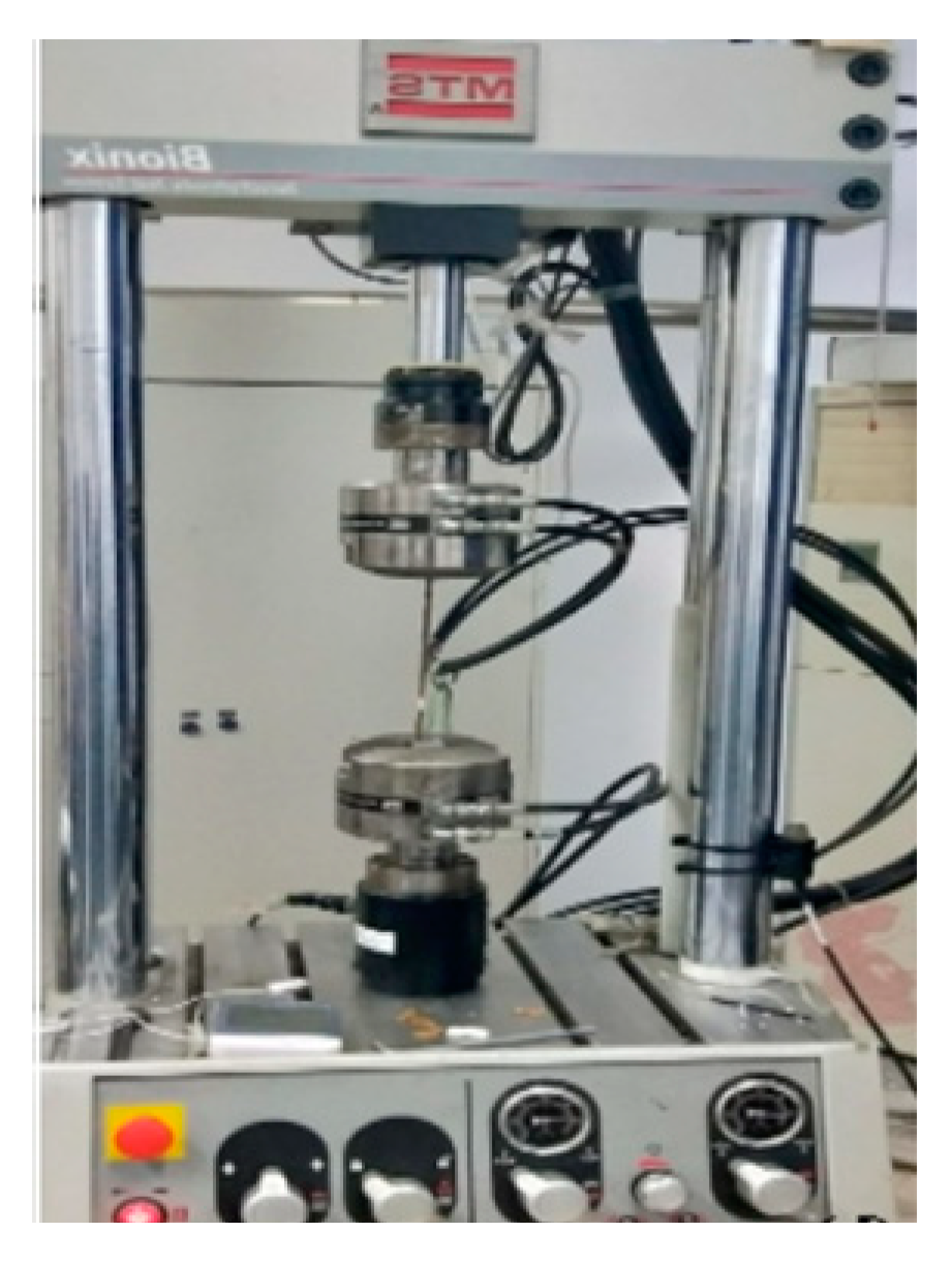
The tensile strength of mechanical parameters of Chinese fir roots was obtained by the uniaxial tensile test. After the root was cleaned, the two ends of the root were processed with cold-embedded epoxy resin to prevent the root from being damaged and skidded in the clamping. The processed root samples were placed in a refrigerator at 4 °C for 48 h for re-hardening. The uniaxial tensile test of roots was carried out under MTS BIonix hydraulic machine (Figure 6).
(2)
Shear resistance test of the root–soil interface bonding strength
(1)
Test principle and instrument
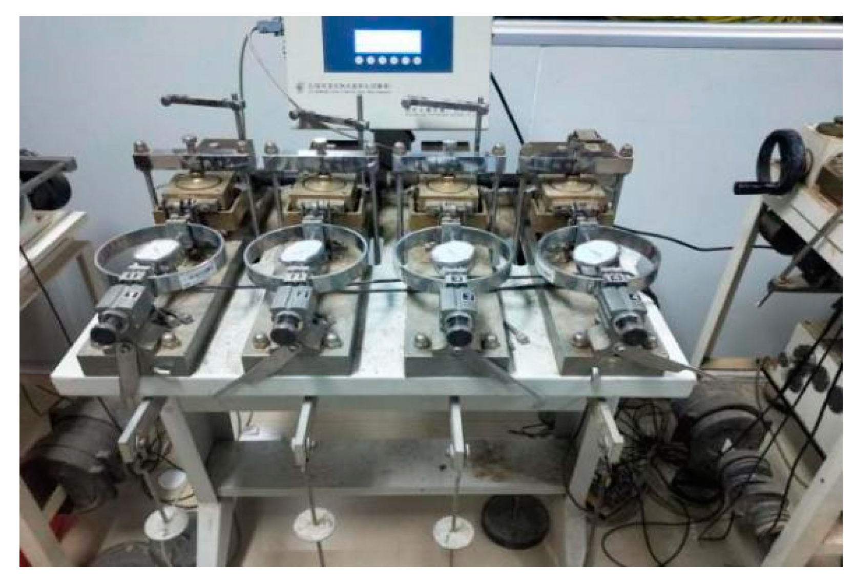
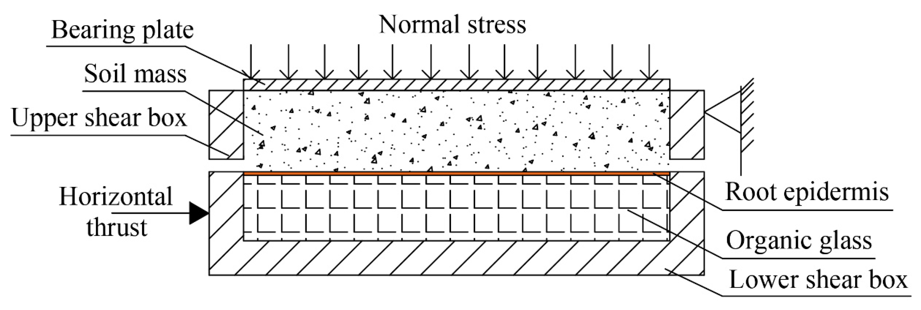
The cross-sectional tissue structure of Chinese fir roots was composed of an epidermis, cortex and column, as shown in (Figure 7). The bond strength of the root–soil interface was the bond strength between the root epidermis and soil, which was tested by the four-way strain-controlled direct shear apparatus (Figure 8). The test principle is similar to the direct shear test in conventional geotechnical tests (Figure 9). The soil sample was placed in the upper box, and the organic glass block adhered to the root epidermis was placed in the lower box of the direct shear apparatus. The diameter of the organic glass block was the same as that of the soil sample, and the upper surface (root surface) was flat with the upper surface of the lower box. The shear resistance test was designed according to “Standard for Geotechnical Test Methods, GB/T 50123-2019”. The compaction state of direct shear samples was based on the dry density of samples. The dry density of RS-I samples and soil samples was 1.11 g/ cm−3. The maximum normal stress of the direct shear instrument is 400 kPa, the horizontal thrust is 1.2 KN, and the accuracy is 5‰ of the measuring range. To simulate the stress state of root–soil separation, the root axis direction was parallel to the shear direction. In the test, the normal stress uniformly acted on the soil sample through the pressure plate, maintained the upper box fixed, and applied the horizontal thrust to push the lower box so that the organic glass block covered with the root epidermis produced relative displacement with the upper box soil. The horizontal thrust and displacement were measured and recorded continuously or at intervals, and the test was stopped when the horizontal displacement exceeded a certain limit. The maximum shear strength of the root–soil interface under different normal stresses was obtained by repeating the above process.
  • (2)
    Specimens preparation and shearing
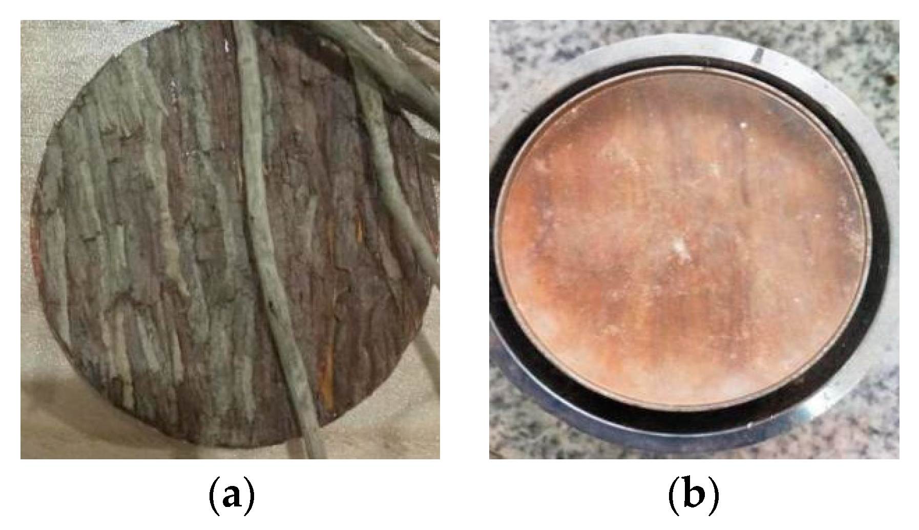
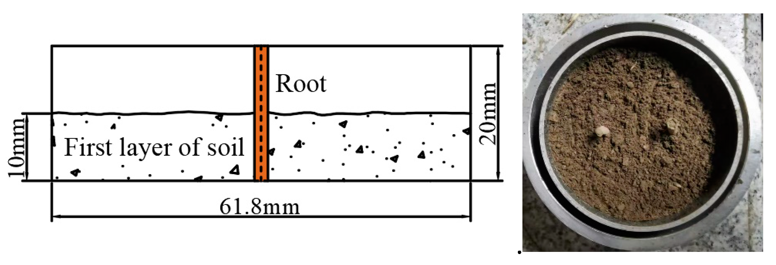
The root epidermis was cut off with roots for experiments where both the epidermis and the cortex were intact (both the epidermis and the cortex were cut off to ensure that the root epidermis was not destroyed) and were glued to a custom organic glass block (Figure 10a). According to the measured dry density of the soil and the size of the shear box, the well-configured test soil was weighed and put into a ring knife with a height of 20 mm and a diameter of 61.8 mm. The organic glass block adhered to the root epidermis was placed on the soil for compaction to ensure the full bonding between the root surface and the soil (Figure 10b). The blank control group was designed, with 4 samples in each group. The specimen number is shown in Table 2. Due to the shallow soil depth, considering the confining pressure of the soil in the actual soil depth, in order to effectively measure the bond strength of root–soil interface, the specimens were sheared at the rate of 0.8 mm/min under the vertical pressure of 25, 50, 75 and 100 kPa, respectively, until the dynamometer reading didn’t change with the increase of shear displacement, and the maximum shear strength of the root–soil interface under each vertical load was obtained.
  • (3)
    Direct shear test of root-permeated soil
Based on the field investigation of root area ratio RAR (field root investigation results show that the average RAR is around 0.6% in the range of root concentrated growth), the root area ratio on the shear plane was 0.21%, 0.42%, 0.63%, 0.84%, 1.05%, the distribution of roots in the shear box was shown in Figure 11. The δ angle between the root and shear direction was 45° and 90°. According to the measured dry density of the soil and the size of the shear box, the well-configured test soil was weighed and compacted in the ring knife based on the arrangement of roots. When the δ angle was 90° (Figure 12), the half-mass soil required for a sample was weighed for preliminary leveling, compaction and shaving, and the other half of the mass soil was filled around the roots for compaction after inserting the roots through the toothpick socket at the position of the pre-designed root; When the δ angle was 45° (Figure 13), the volume of the test soil which accounts for half of the full ring knife was weighed, compacted and scraped according to the 45° inclination angle of the surface, and the prepared root system was laid, and then loaded into the half of the soil for compaction. The total experimental design group of 10 groups, each group of 4 samples, sample number and parameters as shown in Table 3. The installation and shearing of the prepared specimen of root-permeated soil in the four-way strain-controlled direct shear apparatus were consistent with the shear resistance test of the root–soil interface in list item (2) in Section 3.2

4. Experiments Results

4.1. Root Tensile Strength

The relationship curve between tensile force and displacement of Chinese fir root was obtained by the uniaxial tensile test. The tensile force of the root was the peak value of the curve. The tensile strength was calculated by Equation (5). The calculation results are shown in Table 4.
t f = F m a x A f = 4 F m a x π D r 2
where t f is root tensile strength; F m a x is the peak value of tensile force.

4.2. Bond Strength of Root–Soil Interface

The maximum shear strength of soil and root–soil interface under different normal stress was obtained by shear resistance test, as shown in Table 5.
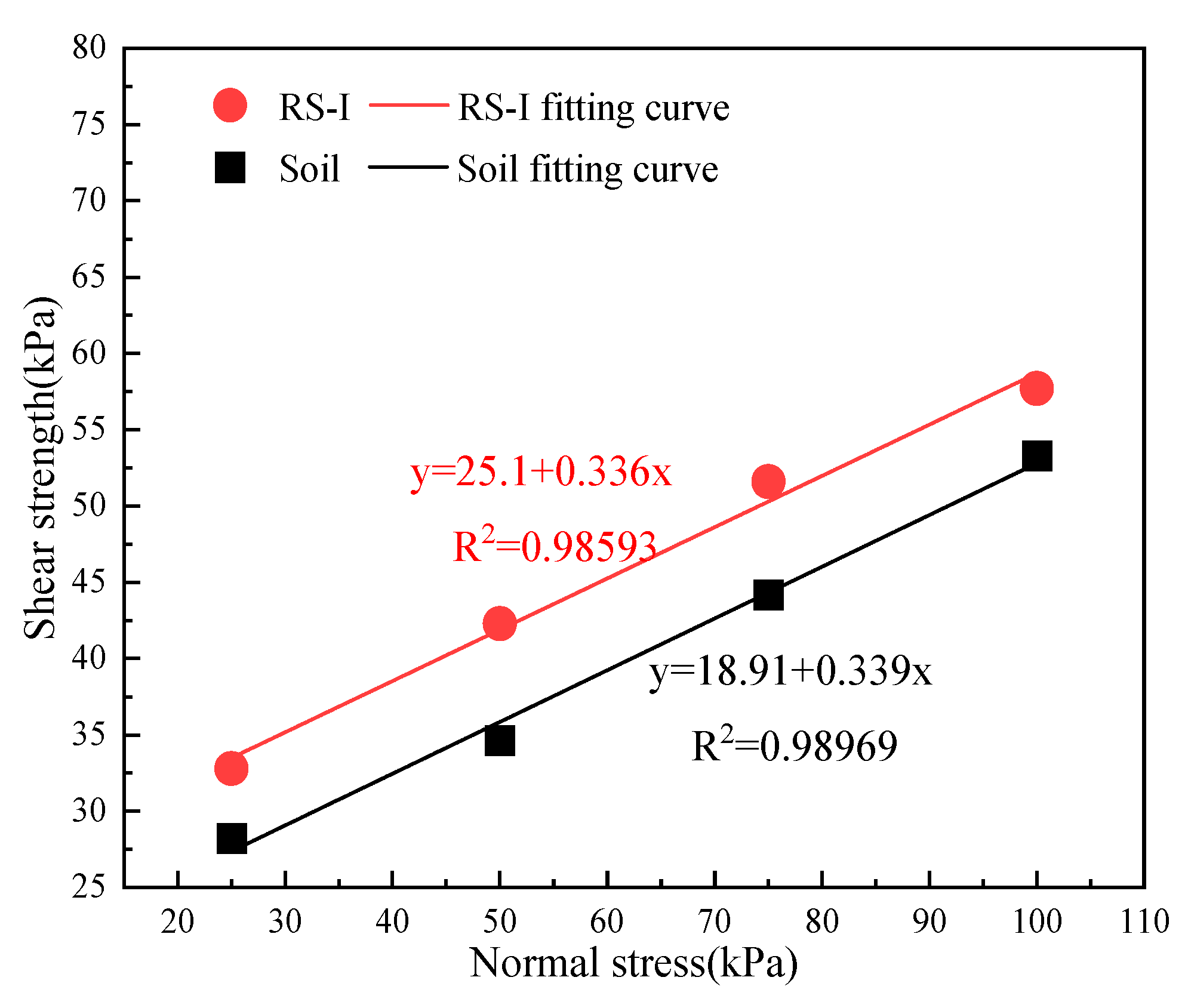
The shear strength test results of soil and root–soil interface under different normal stresses were drawn and linearly fitted in the τ σ coordinate (Figure 14). There is little difference between the internal friction angle of root–soil interface φ r s i and the internal friction angle of the soil φ s o i l . The internal friction angle of root–soil interface φ r s i is influenced by the roughness of soil particles and root surface, root type, soil type, soil particle composition and water content [53]. The close value of φ r s i and φ s o i l is a coincidence caused by these factors. It can be seen from Figure 14 that the root–soil interface bond strength and soil shear strength are positively correlated with the normal stress, and the determination coefficients of the two fitting relationships are almost the same and are greater than 0.98, showing a good correlation. Therefore, the bond strength of the root–soil interface and the normal stress of the interface obey the Coulomb theory, i.e., the bond strength of the root–soil interface τ r s i can be quantified by the strength parameters of the interface cohesion and the interface friction angle (Equation (6)). The strength parameters of soil shear strength and root–soil interface bond strength are shown in Table 6.
τ r s i = C r s i + f r s i = C r s i + σ n tan φ r s i
where C r s i is the cohesion stress of root–soil interface (kPa); f r s i is root–soil interface friction, (kPa); σ n is normal interface stress (kPa); φ r s i is the internal friction angle of the interface (°).

4.3. Shear Strength of Root-Permeated Soil

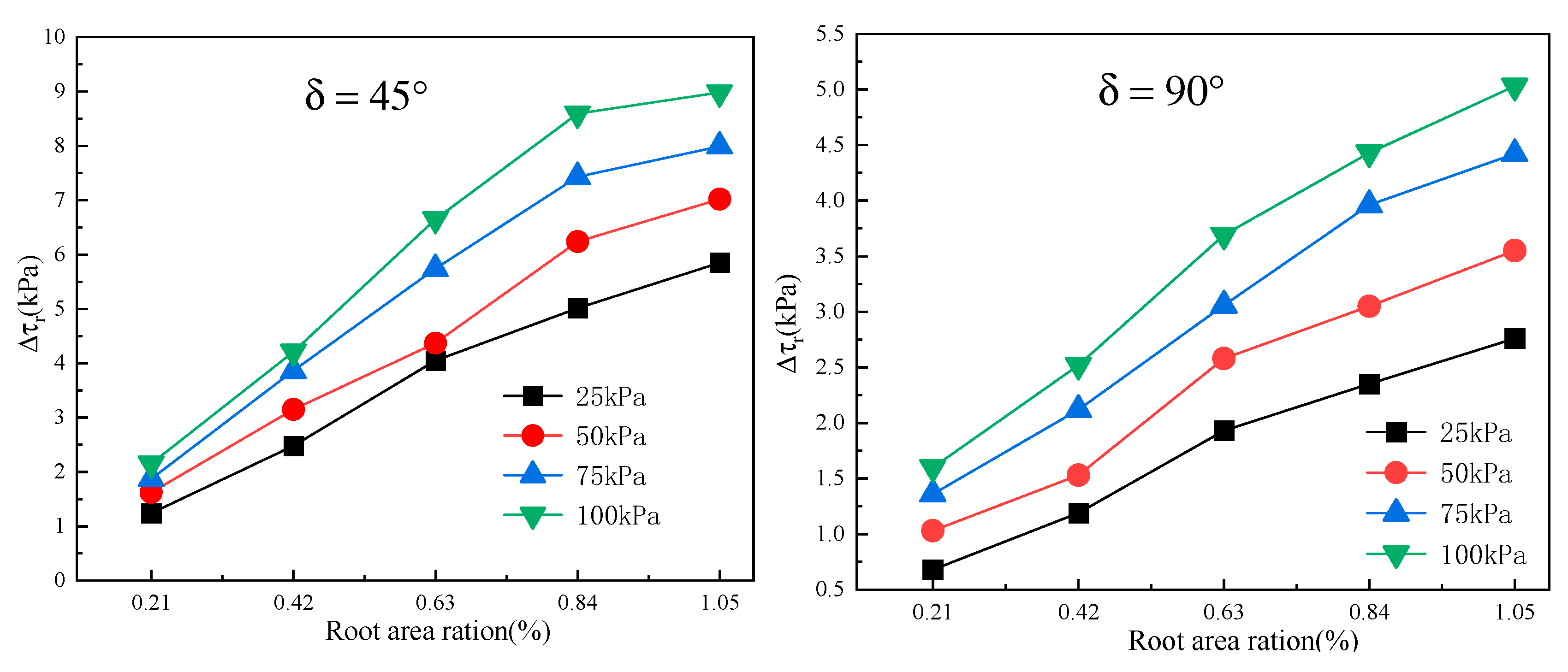
The shear strength of the root-permeated soil under different normal stresses was obtained by direct shear test. The direct shear test results were plotted in the τ σ coordinate, and the shear strength parameters of the specimens were obtained by linear fitting, as shown in Table 7. The shear strength difference between the root-permeated soil and the soil in Table 5 is root reinforcement, as shown in Figure 15.
The shear strength of different root-permeated soil samples is significantly higher than that of rootless soil samples, and the root reinforcement value is greater than 0, which increases with the normal stress. When the root area ratio is constant, the relationship between roots reinforcement and the angle between the root and the shear direction in the root-permeated soil is that the δ angle of 45° is greater than 90°; When the δ angle between root and shear direction is the same, the roots reinforcement increases with the root area ratio of root-permeated soil.

5. Establishment and Validation of Estimation Model of the Ultimate Shear Strength of Root-Permeated Soil Fully Considering Interface Bonding

5.1. Model Establishment

As previously introduced, the present shear strength calculation model of root-permeated soil (Section 2) mainly considered the failure mode and deformation of roots; however, the analysis of the bonding effect of the root–soil interface was insufficient, and model parameters are complex and difficult to obtain. Therefore, on the basis of Wu’s model (simple parameters and wide application range), combined with two failure models of roots in root-permeated soil, this paper fully considered the bonding effect of the root–soil interface to establish the estimation model of the ultimate shear strength of root-permeated soil. The schematic diagram of the estimation model is shown in Figure 16, assuming that:
(1)
When analyzing the interaction between plant roots and soil, the three-dimensional reinforcement was simplified to a two-dimensional plane state.
(2)
Due to the great difference in deformation modulus and material properties between plant roots and soil, the soil-permeated root could be regarded as anisotropic composite materials, and the roots were equivalent to flexible tensile components in the soil.
(3)
The tensile stress of roots could be decomposed into the normal stress and tangential stress on the shear surface of the soil, where the normal stress enhanced the friction strength on the shear surface, and the tangential stress could be directly involved in resisting the shear deformation of soil on both sides of the shear surface.
The single root reinforcement was:
Δ τ r a = t r A r A s ( sin θ + cos θ tan φ ) = R θ t r R A R a
where t r is the tensile stress of root (kPa); R θ is the factor that characterizes the root deformation angle with R θ = sin θ + cos θ tan φ .
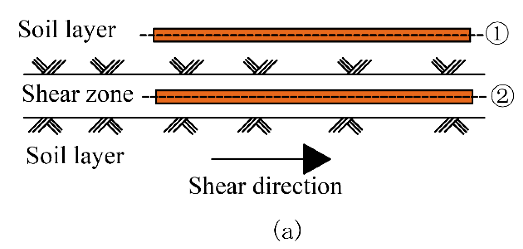
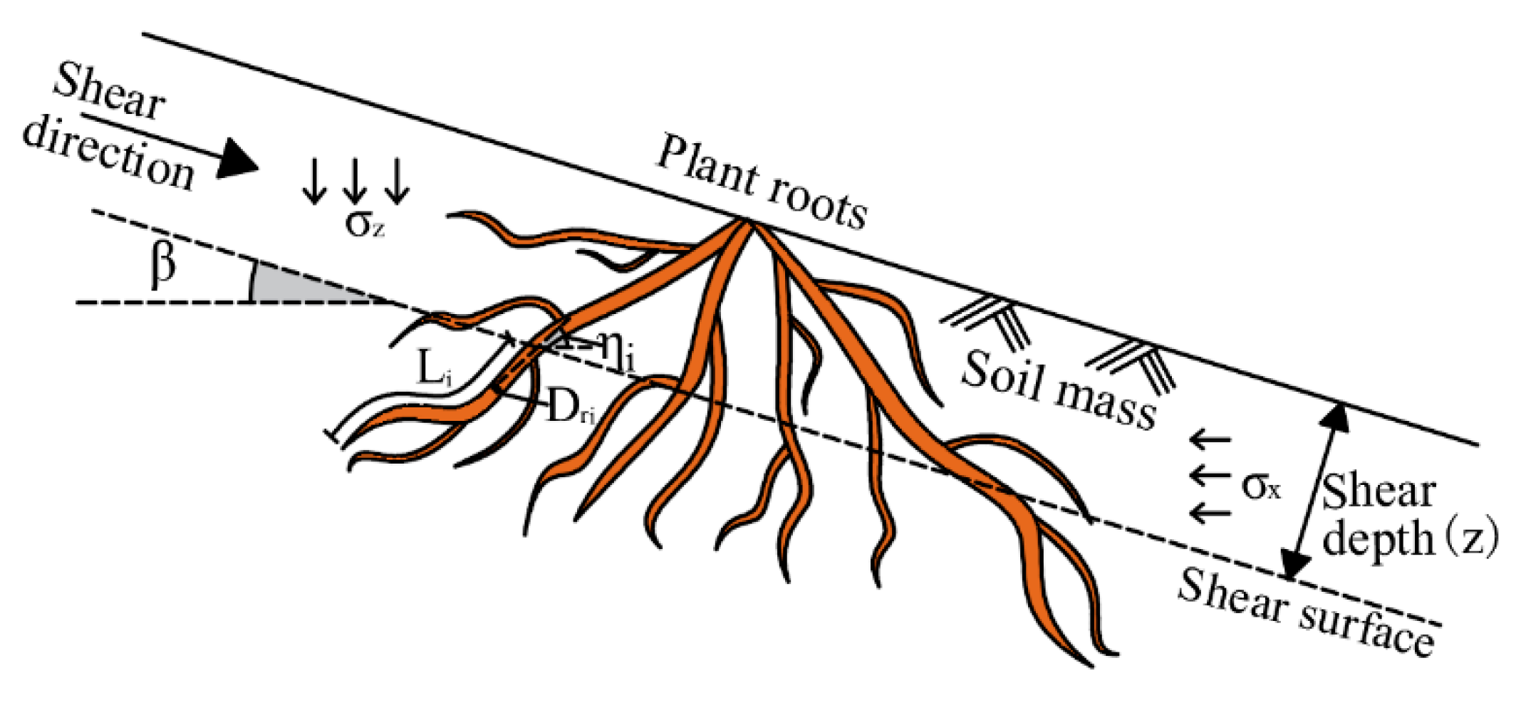
When the root-permeated soil was subjected to shear, the roots converted the internal shear stress of the soil into the tensile stress of itself through the bonding effect of the root–soil interface so that the tensile force of the root, the bonding force of the root–soil interface and the shear resistance of the soil jointly acted to achieve the mechanical reinforcement of the roots to the soil. The tensile force of the root in the root-permeated soil is estimated by the bond force of the root–soil interface, which depends on the bond strength, root diameter and root length under the shear plane. The force analysis of the root segment micro-element below the shear plane in Figure 16b was carried out, and the following force balance equation was obtained:
d T r = τ r s i π D r d l
0 T r d T r = 0 L τ r s i π D r d l
T r = τ r s i π D r L
where T r is the tensile force of root (kN); τ r s i is the bond strength of the root–soil interface (kPa); D r is the root diameter (m); L is the length of root under the shear plane (m).
The tensile stress of the root was:
t r = T r A r = 4 τ r s i π D r L π D r 2 = 4 τ r s i L D r
The bond strength of the root–soil interface τ r s i is controlled by the normal stress of the interface, the mechanical properties of the soil and the root roughness. The interfacial bond strength is composed of interfacial cohesion stress and interfacial friction force (Equation (5)). The interface cohesive stress C r s i is made up of interface chemical cohesive stress and interface soil cohesive stress, which provides the first part of bond strength for the root–soil interface. The interface chemical cohesive stress was provided by the chemical cohesion effect of the chemical substances secreted from the root surface during the root growth [54]. When the roots and soil slide locally, the cohesive chemical stress is lost, and the remolded root-permeated soil does not have this part of cohesion. The interaction between soil particles and root surface constitutes the interface soil cohesion, and when the root slides inside the soil, the cohesion of the root–soil interface fails.
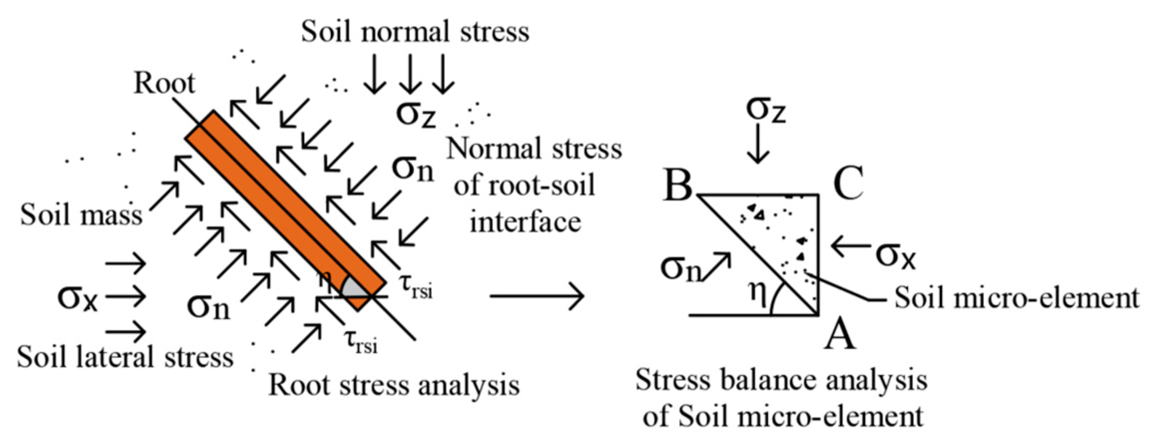
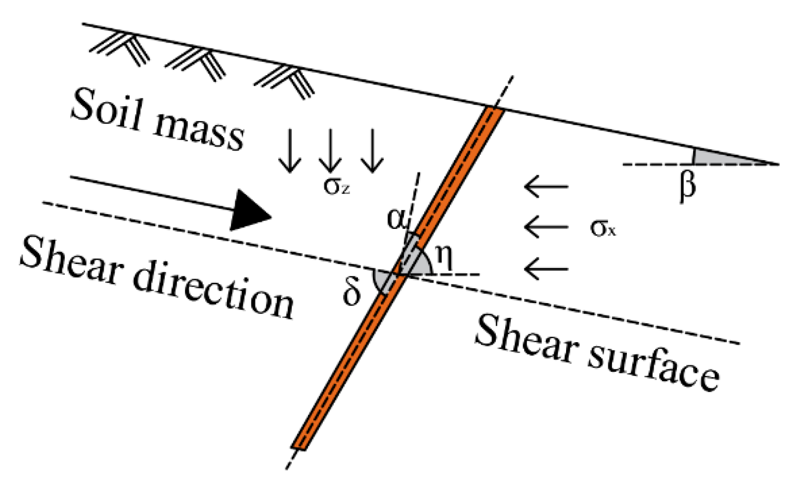
The interface friction force f r s i provides the second part of bond strength for the root–soil interface. When the root and soil move or tend to move each other, the local bulge of the root surface will squeeze the surrounding soil, and the mechanical occlusion between the root and soil interface forms strong interfacial friction. The interfacial friction resistance depends on the interfacial normal stress σ n and the interfacial friction angle φ r s i . The normal stress of the interface is controlled by the stress state of the soil and the angle η between the root and the lateral stress direction of the soil. A micro-unit ABC in the soil was set as a plane stress state, and the normal stress diagram acting on the root–soil interface was shown in Figure 17.
Based on the force balance condition, the normal stress analysis on the root–soil interface of inclined roots with the angle of η to the lateral stress direction of soil was as follows:
σ n A B ¯ = σ x A C ¯ sin η + σ z B C ¯ cos η
σ n = σ x + σ z 2 + σ z σ x 2 cos 2 η
where σ z is the normal stress at any point in the soil (kPa); σ x is the lateral stress at any point in the soil (kPa); η is the angle between the root and the lateral stress direction of the soil (°).
If the lateral stress direction of soil was consistent with the shear direction, then η = δ = 90 α . When δ = 90 , the root was perpendicular to the shear direction, and there was:
σ n = σ x = K 0 σ z
where K 0 is the static lateral pressure coefficient of soil. The lateral pressure coefficients of different soil types are different, which can be determined by the special K 0 test, by the empirical formula K 0 = 1 sin φ [55] or by referring to the specification manual.
There are two types of root failure in the shear deformation of root-permeated soil, namely tension fracture (good root–soil interface bonding) and pull-out failure (partial root–soil interface bonding failure). If the length of the root beneath the shear surface is long enough to penetrate the soil, or the root–soil interface bonding force is large enough to make the root tensile stress exceeds the ultimate tensile strength, then the root is broken. On the contrary, if the length of the root below the shear plane penetrates into the soil is short, or the root–soil interface bonding force is small, and the tensile stress of the root is less than the ultimate tensile strength, then with the increase of shear displacement, the root is pulled out, namely the bonding of root–soil interface is destroyed. Based on the root failure type of tension fracture (good root–soil interface bonding) in root-permeated soil, it was assumed that the root–soil interface bond was not destroyed when the root was broken, i.e., the maximum tensile stress of the root was estimated by the maximum bond strength of root–soil interface. Assuming that the cohesive stress of root–soil interface was destroyed due to the relative sliding of the root–soil interface, the bond strength of the root–soil interface was only provided by the friction component, i.e., the minimum tensile stress of the root was estimated by the minimum bond strength of root–soil interface. Therefore, the root tensile stress limit could be estimated by the root–soil interface bond strength corresponding to different root failure types, and then the root reinforcement limit could be estimated. The specific analysis was as follows.
(1)
Maximum
On the assumption that the root didn’t occur interfacial bond failure during the shear deformation of the root-permeated soil, i.e., the interfacial bond strength was provided by the interfacial cohesion and friction. The maximum tensile force of the root was calculated by the maximum bond strength of interfaces so as to estimate the maximum value of root reinforcement in root-permeated soil. The maximum tensile stress was calculated through Equations (15)–(20).
The maximum tensile stress of the root was:
t r h = 4 τ r s i h L D r
where τ r s i h is the maximum bond strength of root–soil interface (kPa), which is calculated by Equation (6).
The maximum tensile stress t r h of the root in Equation (12) can’t exceed the tensile strength t f of the root, i.e., in the calculation, when t r h < t f , the maximum tensile stress of root is t r h ; When t r h < t f , the maximum tensile stress of root is t f .
In this case, the maximum reinforcement of a single root was:
Δ τ r h a = R θ h t r h R A R a
where R θ h is the factor representing the root deformation angle under the assumption of maximum value, R θ h = sin θ h + cos θ h tan φ , and θ h is the angle between a single root and the normal direction of the shear plane under the assumption of maximum value. Since the variation range of θ h is 0–90°, and it is difficult to accurately measure in the actual soil with roots, R θ h is a range value, in which the maximum value is [ 1 + tan ( 2 φ ) ] 1 / 2 .
The above formula was simplified as follows:
Δ τ r h a = 1 + tan 2 φ t r h R A R a
The maximum reinforcement of group root was:
Δ τ r h = 1 + tan 2 φ i = 1 n t r h i R A R i
where t r h i is the maximum tensile stress of the ith root in the soil (kPa).
If the maximum tensile stress of roots in root-permeated soil is taken as an average, the maximum reinforcement of roots is as follows:
Δ τ r h = 1 + tan 2 φ R A R t ¯ r h
where RAR is the root area ratio of soil (%), calculated by the following formula.
R A R = i = 1 n A r i A s = i = 1 n π D r i 2 4 A s
(2)
Minimum
Based on this, the minimum tensile stress of roots could be estimated to calculate the minimum value of root reinforcement in root-bearing soil. The minimum tensile stress was calculated through Equations (21)–(27).
The minimum tensile stress of the root was:
t r l = 4 τ r s i l L D r
where τ r s i l is the minimum bond strength of root–soil interface (kPa), calculated by the following equation.
τ r s i l = f r s i = σ n tan φ r s i
where σ n is the normal stress of the interface (kPa), calculated by Equation (11).
The minimum reinforcement of a single root was:
Δ τ r l a = R θ l t r l R A R a
where R θ l is the factor representing the root deformation angle under the assumption of minimum value, R θ l = sin θ l + cos θ l tan φ , and θ l is the angle between a single root and the normal direction of the shear plane under the assumption of minimum value. Since R θ l is a range value, to obtain the minimum value of Equation (20), R θ l was simplified and analyzed as follows:
R θ l = 1 + tan 2 φ sin ( θ l + φ )
In the above equation, when sin ( θ l + φ ) is the minimum value, R θ l  is the minimum value, where φ is the internal friction angle of soil, which is a constant value in the calculation, and θ l is the range of 0–90°:
When 0 ° φ 45 ° , the minimum value of sin ( θ l + φ ) is sinφ as shown in Figure 18a, then the minimum value of R θ l is:
R θ l = 1 + tan 2 φ sin φ
When 45 ° < φ < 90 ° , the value of sin ( θ l + φ ) is shown in Figure 18b. When 0 ° θ l 2 ( 90 ° φ ) , the minimum value of sin ( θ l + φ ) is sin φ , then the minimum value of R θ l is shown in Equation (22); when 2 ( 90 ° φ ) < θ l 90 ° , the minimum value of sin ( θ l + φ ) is sin ( θ l + φ ) , then the minimum value of R θ l is shown in Equation (21).
The minimum reinforcement of group root was:
Δ τ r l = R θ l i = 1 n t r l i R A R i
where t r l i is the minimum tensile stress of the i-th root in the soil (kPa).
If the minimum tensile stress of roots in root-permeated soil is taken as an average, the minimum reinforcement of roots is as follows:
Δ τ r l = R θ R A R t ¯ r l

5.2. Model Validation

In order to verify the rationality and advancement of the estimation model of the ultimate shear strength of root-permeated soil established in this study, based on the direct shear test results of root-permeated soil (Section 4.3), the calculation parameters obtained from the root tensile test (Section 4.1) and root–soil interface shear resistance test (Section 4.2) were brought into the estimation model and Wu’s model to calculate the shear strength of root-permeated soil. Thus, the measured values, estimation model calculation interval and Wu’s model calculation values of shear strength of root-permeated soil are compared. In the direct shear test with root-permeated soil, the lateral stress direction of the soil was consistent with the shear direction, i.e., the angle between the root and the lateral stress direction of the soil was η = δ . The calculation parameters of the calculation model are shown in Table 8.
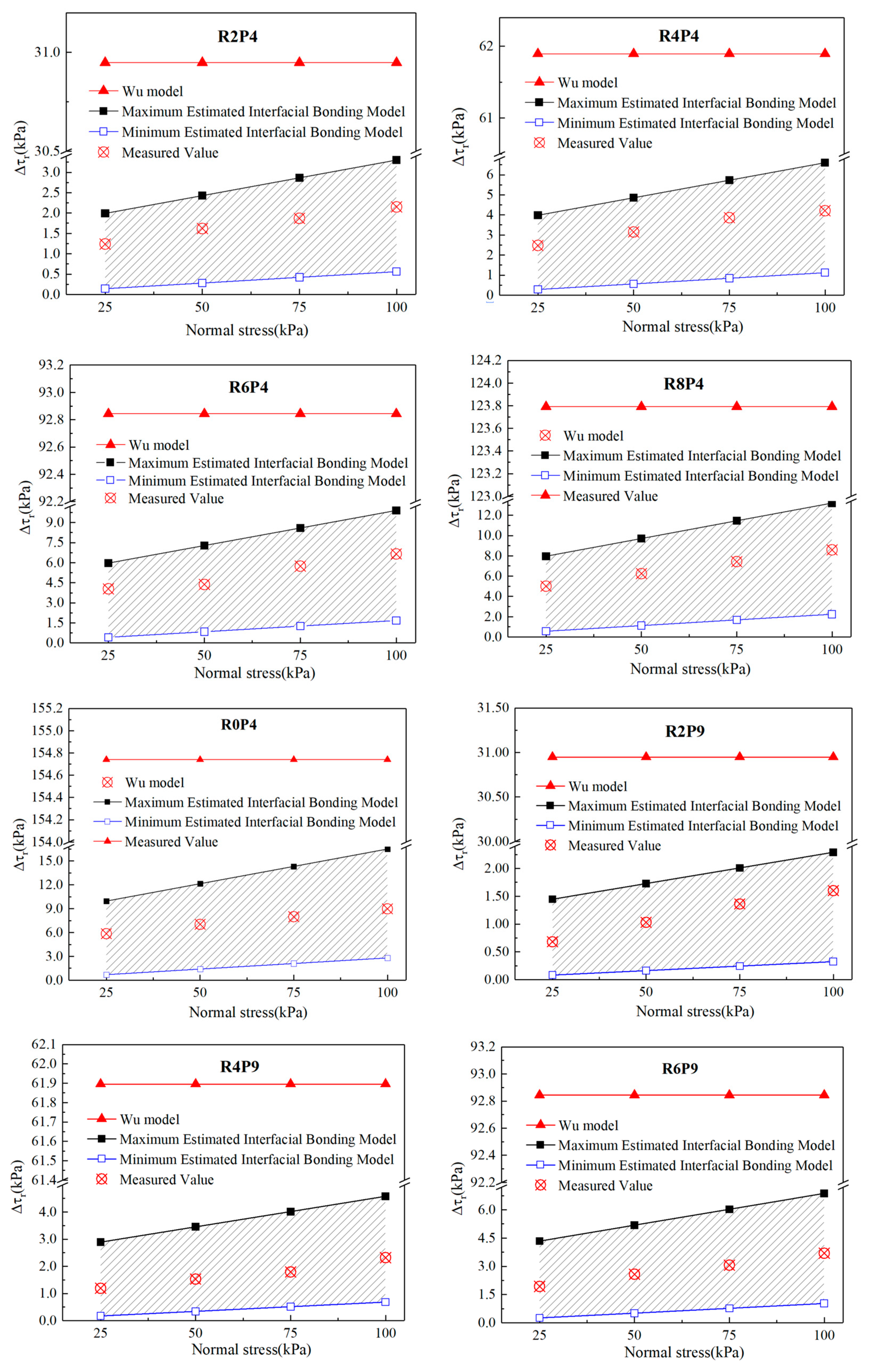
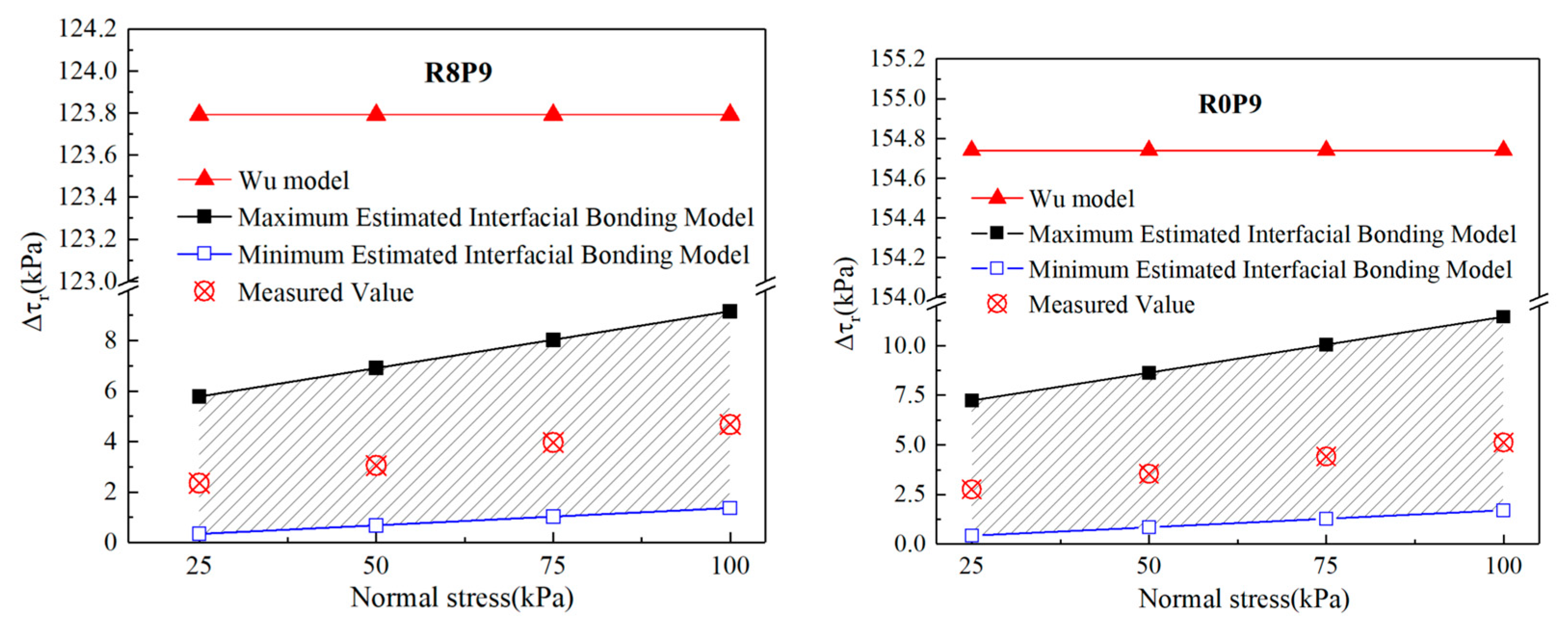
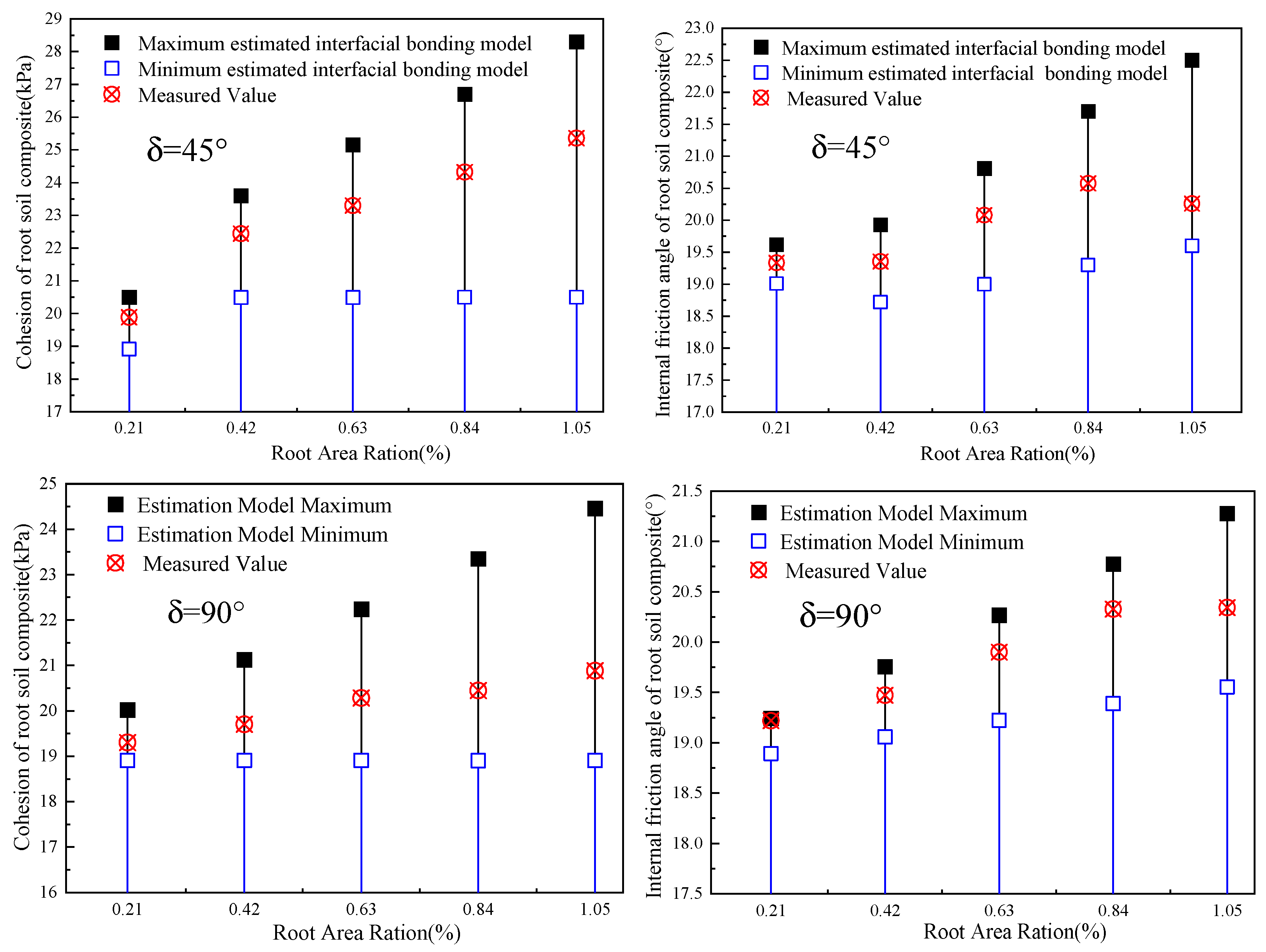
The calculation parameters in Table 8 are introduced into the estimation model established in this paper and Wu’s model to calculate the shear strength of the root-permeated soil. The difference in the shear strength of the root-permeated soil estimated by the two calculation models was reflected in the different calculations of root reinforcement. Therefore, the measured value of root reinforcement was compared with the calculated value range of the estimation model and the calculated value of Wu’s model. The results are shown in Figure 18. The ultimate shear strength of root-permeated soil calculated by the estimation model established in this paper was plotted in the τ σ coordinate, and the model-calculated value of shear strength parameters obtained by linear fitting was compared with the measured value, as shown in Figure 19.
As shown in Figure 18 and Figure 19, the measured values of roots reinforcement and shear strength parameters of root-permeated soil obtained from the direct shear test were within the range of the calculated limit values of the estimation model established in this article. It indicates that in the process of shear deformation of the root-permeated soil, the partial sliding of the root relative to the soil led to the partial failure of the interface cohesion. The bond strength of the root–soil interface was between the maximum and minimum value of the interface cohesion component that was not destroyed and all the destruction. It was proved that the estimation model in this research is reasonable to calculate the ultimate shear strength of the root-permeated soil based on the limit value of the root–soil interface bond strength. The accuracy of different calculation models was defined as the calculated value divided by the measured value from the experiment. The comparison between the calculation values of the estimation model in this paper and the calculation values of Wu’s model shows: When the δ angle was 45°, the calculated value of Wu’s model was 19 times the measured value on average, and the calculation accuracy of the estimated model was 3.4 times higher. When the δ angle was 90°, the calculated value of Wu’s model was 36 times the measured value on average, and the calculation accuracy of the estimation model was increased by 7.2 times. Compared with the measured values, the estimated root reinforcement by Wu’s model was 27 times higher on average. The calculation accuracy of the estimated model established in this paper was five times higher than that of Wu’s model on average, indicating that it is more reasonable to calculate the tensile stress of roots by fully considering the bonding effect of root–soil interface than directly using the tensile strength of roots in the model to estimate the shear strength of soil-permeated roots. In addition, the estimation model established can reflect the characteristics that root reinforcement increased with the normal stress, while the calculated value of Wu’s model didn’t change with the normal stress.

6. Discussion

6.1. Scope of Application of the Estimation Model

(1)
Mechanical properties of roots
In the estimation model of the ultimate shear strength of root-permeated soil based on interface bonding, roots were assumed to be flexible tensile components, and the shear stress part of the soil was transformed into the root tensile force through the bonding effect of root–soil interface. In other words, it was assumed that roots only occurred tensile strain in the axial direction, and the total stress on the cross-section of roots was the axial tensile stress, without considering the bending stress and shear stress of the cross-section. Therefore, the model is suitable for the herbaceous vegetation roots and the lateral roots of woody vegetation roots with smaller root diameters and smaller stiffness that can be regarded as flexible tensile components.
(2)
Orientation of roots relative to the shear plane
The estimation model established in this paper decomposed the tensile stress generated by the roots in the root-permeated soil on the shear surface to estimate roots reinforcement, in which the normal component increased the normal stress on the shear surface, and the tangential component was directly involved in resisting the shear deformation of the soil on both sides of the shear surface. Therefore, the model is suitable for the roots which pass through the soil shear plane and have a certain angle with the shear direction, i.e., RAR ≠ 0 and 0 ° < δ 90 ° . As shown in Figure 20, the roots in root-permeated soil didn’t pass through the shear surface, were parallel to the shear plane and had an angle greater than 90° with the shear direction, which wasn’t within the calculation range of the estimation model.

6.2. Model Parameters

(1)
Soil strength parameters
As shown in Equation (6), the model for estimating the ultimate shear strength of root-permeated soil established in this paper assumed that the roots provided an additional strength for the soil without affecting the strength parameters of the soil itself, namely the shear strength of root-permeated soil was estimated on the basis of the shear strength of the soil (cohesion c and internal friction angle φ ). Therefore, the shear strength parameters of the soil are the basic parameters in the estimation model, which are obtained through indoor direct shear or triaxial shear tests.
(2)
Bond strength parameters of root–soil interface
The bond strength parameters of root–soil interface are an important calculation parameter in the estimation model. In the model, the root reinforcement was estimated by calculating the ultimate tensile stress of roots. The maximum tensile stress of roots was estimated based on the maximum bond strength parameter of the interface (interfacial cohesion C r s i  and interfacial friction angle φ r s i ). The minimum tensile stress of roots was estimated based on the minimum bond strength parameter of the interface (interfacial friction angle φ r s i ). In-situ interfacial bond strength parameters are obtained by in-situ pull-out test [56], and remodeling interfacial bond strength parameters are obtained by indoor pull-out test [57] or shear resistance test [58], with a wide range of minimum and maximum values of the obtained strength values. In practical application, the minimum value is used for safety considerations, and the average value is generally taken.
(3)
Tensile strength of roots
Theoretically, if the bond strength of the root–soil interface is large enough, when the root diameter is constant, the tensile stress of the root increases with the root burial depth under the shear surface, but it cannot exceed the tensile strength t f of the root. Therefore, the tensile strength parameters of roots are also an integral part of the calculation parameters of the model, which are obtained through the uniaxial tensile test of roots.
(4)
Spatial geometric characteristic parameters of roots
The spatial geometric characteristics of roots are closely related to the mechanical reinforcement of roots in root-permeated soil. They are important calculation parameters in the estimation model, which can be divided into three categories: quantity parameters, size parameters and orientation parameters. The number parameter is the number of roots n, the size parameters are root diameter Dr, single root area ratio RARi and root length under the shear surface L, and the orientation parameters are the angle between root and shear direction δ , the initial angle α between root and shear surface normal, the angle η between root and soil lateral stress direction, and the angle θ between root and shear plane normal after deformation. However, the orientation parameters are not independent of each other. When the shear direction was parallel to the lateral stress direction of soil (Figure 16), α = 90 ° δ and η = δ ; When the shear direction was not parallel to the lateral stress direction of soil (Figure 21), the lateral stress direction of soil was horizontal, and the shear direction was parallel to the slope direction, where the slope was β , then η + β = δ and α = 90 ° η β . The angle θ is correlated with the angles of α and η . Since it is difficult to monitor θ , the range value of θ ( 0 ° < θ < 90 ° ) was directly brought into the model for calculation. Finally, through simplification, the model calculation formula didn’t contain the unknown θ when the internal friction angle φ was within a certain range ( 0 ° φ 45 ° ; 45 ° < φ < 90 ° and 0 ° θ 2 ( 90 ° φ ) . Therefore, the root’s spatial geometric parameters required for estimating the shear strength of a plant roots at a certain shear depth include the number of roots crossing the shear surface n, the diameter of roots Dr, the length of roots under the shear surface L, the angle between root and soil lateral stress direction η and slope β (Figure 22).

7. Conclusions

In the present work, the bonding strength of root–soil interfaces was analyzed and quantified through laboratory experiments. The shear strength of root-permeated soil with different root ratios and root inclination angles was tested and analyzed. Based on the bonding effect of the root–soil interface, an estimation model of the shear strength limit value of root-permeated soil with simple parameters and relatively high accuracy was established. The rationality of the estimation model was verified by comparing it with the experimental results. The specific conclusions are as follows:
(1)
Experimental results of bond strength of root–soil interface and shear strength of root-permeated soil: The shear resistance tests of root–soil interface bonding strength showed that the interface bond strength and the interface normal stress were in accordance with the Coulomb’s law, which could be quantified by the interface cohesion and the interface friction angle. The indoor direct shear test results showed that the mechanical reinforcement of roots in the root-permeated soil increased with the root area ratio and normal stress. The shear strength of root-permeated soil in the condition of a 45° Angle between the root system and shear direction was greater than that in a 90° Angle.
(2)
The characteristics and application range of the proposed shear strength model of root-permeated soil: The bond effect of root–soil interface was fully considered, and the estimation model of ultimate shear strength of root-permeated soil was established by combining with Wu’s model. The estimation model realizes the estimation of ultimate shear strength (maximum and minimum) of root-permeated soil considering soil stress, root diameter, root length and initial angle between root and shear direction. The model is suitable for herbaceous roots and lateral roots of woody plants with small stiffness and sharp angle across the shear plane.
(3)
Verification of rationality and advancement of the proposed estimation model: The proposed estimation model was quantitatively compared with the results of the direct shear test and Wu’s model. The results showed that the measured root reinforcement and the shear strength parameters of root-permeated soil were within the range of the calculated values of the estimation model. Moreover, the accuracy of the estimation model was five times higher than that of Wu’s model on average. Therefore, the established estimation model can reasonably and effectively estimate the shear strength of the root-permeated soil and be used to calculate the stability of biotechnical reinforcement landslides.

Author Contributions

Conceptualization, P.N. and X.X.; methodology, P.N., X.X. and Y.J.; validation, P.N., X.X. and Y.J.; formal analysis, P.N.; investigation, P.N. and X.X.; data curation, P.N., X.X. and Y.J.; writing—original draft preparation, P.N. and X.X.; writing—review and editing, X.X.; visualization, Y.J.; supervision, P.N. and X.X.; project administration, Y.J.; funding acquisition, Y.J. All authors have read and agreed to the published version of the manuscript.

Funding

This research was funded by the Strategic Priority Research Program of the Chinese Academy of Sciences (XDA 23090202), the International Science & Technology Cooperation Program of China (2018YFE0100100) and the National Natural Science Foundation of China (Grant Nos. 42172320).

Data Availability Statement

We support data transparency. The main experimental and computational data of this study are presented in the figures and tables of this paper. For detailed experimental curve data and calculation procedures, please contact the corresponding author at email: [email protected].

Acknowledgments

The authors acknowledge Supported by the Science and Technology Research Program of Institute of Mountain Hazards and Environment, Chinese Academy of Sciences. We also thankful the guidance provided by peer review experts and the support of journal editors for this article.

Conflicts of Interest

The authors declare no conflict of interest.

References

  1. Fowze, J.S.M.; Bergado, D.T.; Soralump, S.; Voottipreux, P.; Dechasakulsom, M. Rain-triggered landslide hazards and mitigation measures in Thailand: From research to practice. Geotext. Geomembr. 2012, 30, 50–64. [Google Scholar] [CrossRef]
  2. Shen, P.; Zhang, L.M.; Chen, H.X.; Gao, L. Role of vegetation restoration in mitigating hillslope erosion and debris flows. Eng. Geol. 2017, 216, 122–133. [Google Scholar] [CrossRef]
  3. Lotfalian, M.; Nasiri, M.; Modarres, A.; Wu, W. Slope stability analysis considering weight of trees and root reinforcement. J. Environ. Eng. Landsc. Manag. 2019, 27, 201–208. [Google Scholar] [CrossRef]
  4. Tan, H.; Chen, F.; Chen, J.; Gao, Y. Direct shear tests of shear strength of soils reinforced by geomats and plant roots. Geotext. Geomembr. 2019, 47, 780–791. [Google Scholar] [CrossRef]
  5. Zhu, H.; Zhang, L.M. Field investigation of erosion resistance of common grass species for soil bioengineering in Hong Kong. Acta Geotech. 2016, 11, 1047–1059. [Google Scholar] [CrossRef]
  6. Zydroń, T.; Gruchot, A. Influence of root systems of deciduous trees on soil reinforcement—A case study from the carpathians, poland. Environ. Eng. Manag. J. 2021, 20, 419–433. [Google Scholar] [CrossRef]
  7. Gonzalez-Ollauri, A.; Mickovski, S.B. Plant-soil reinforcement response under different soil hydrological regimes. Geoderma 2017, 285, 141–150. [Google Scholar] [CrossRef]
  8. Ng, C.W.W.; Ni, J.J.; Leung, A.K. Effects of plant growth and spacing on soil hydrological changes: A field study. Geotechnique 2020, 70, 867–881. [Google Scholar] [CrossRef]
  9. Yildiz, A.; Graf, F.; Rickli, C.; Springman, S.M. Assessment of plant-induced suction and its effects on the shear strength of rooted soils. Proc. Inst. Civ. Eng. Geotech. Eng. 2019, 172, 507–519. [Google Scholar] [CrossRef]
  10. Zhu, H.; Indupriya, M.; Gadi, V.K.; Sreedeep, S.; Mei, G.X.; Garg, A. Assessment of the coupled effects of vegetation leaf and root characteristics on soil suction: An integrated numerical modeling and probabilistic approach. Acta Geotech. 2020, 15, 1331–1339. [Google Scholar] [CrossRef]
  11. Mao, Z.; Saint-André, L.; Genet, M.; Mine, F.X.; Jourdan, C.; Rey, H.; Courbaud, B.; Stokes, A. Engineering ecological protection against landslides in diverse mountain forests: Choosing cohesion models. Ecol. Eng. 2012, 45, 55–69. [Google Scholar] [CrossRef]
  12. Bordoloi, S.; Ng, C.W.W. The effects of vegetation traits and their stability functions in bio-engineered slopes: A perspective review. Eng. Geol. 2020, 275, 105742. [Google Scholar] [CrossRef]
  13. Leung, A.K.; Garg, A.; Ng, C.W.W. Effects of plant roots on soil-water retention and induced suction in vegetated soil. Eng. Geol. 2015, 193, 183–197. [Google Scholar] [CrossRef]
  14. Schmaltz, E.M.; Mergili, M. Integration of root systems into a GIS-based slip surface model: Computational experiments in a generic hillslope environment. Landslides 2018, 15, 1561–1575. [Google Scholar] [CrossRef]
  15. Vannoppen, W.; De Baets, S.; Keeble, J.; Dong, Y.; Poesen, J. How do root and soil characteristics affect the erosion-reducing potential of plant species? Ecol. Eng. 2017, 109, 186–195. [Google Scholar] [CrossRef]
  16. Stokes, A.; Douglas, G.B.; Fourcaud, T.; Giadrossich, F.; Gillies, C.; Hubble, T.; Kim, J.H.; Loades, K.W.; Mao, Z.; McIvor, I.R.; et al. Ecological mitigation of hillslope instability: Ten key issues facing researchers and practitioners. Plant Soil 2014, 377, 1–23. [Google Scholar] [CrossRef]
  17. Mahannopkul, K.; Jotisankasa, A. Influences of root concentration and suction on Chrysopogon zizanioides reinforcement of soil. Soils Found. 2019, 59, 500–516. [Google Scholar] [CrossRef]
  18. Yildiz, A.; Graf, F.; Rickli, C.; Springman, S.M. Determination of the shearing behaviour of root-permeated soils with a large-scale direct shear apparatus. Catena 2018, 166, 98–113. [Google Scholar] [CrossRef]
  19. Fan, C.C.; Tsai, M.H. Spatial distribution of plant root forces in root-permeated soils subject to shear. Soil Tillage Res. 2016, 156, 1–15. [Google Scholar] [CrossRef]
  20. Meijer, G.J.; Knappett, J.A.; Bengough, A.G.; Bull, D.J.; Liang, T.; Muir Wood, D. DRAM: A three-dimensional analytical model for the mobilisation of root reinforcement in direct shear conditions. Ecol. Eng. 2022, 179, 106621. [Google Scholar] [CrossRef]
  21. Meijer, G.J.; Bengough, G.; Knappett, J.; Loades, K.; Nicoll, B.; Mukov, I.; Zhang, M. In situ root identification through blade penetrometer testing—Part 1: Interpretative models and laboratory testing. Géotechnique 2018, 68, 303–319. [Google Scholar] [CrossRef]
  22. Meijer, G.J.; Bengough, G.; Knappett, J.; Loades, K.; Nicoll, B.; Mukov, I.; Zhang, M. In situ root identification through blade penetrometer testing—Part 2: Field testing. Géotechnique 2018, 68, 320–331. [Google Scholar] [CrossRef]
  23. Schwarz, M.; Cohen, D.; Or, D. Root-soil mechanical interactions during pullout and failure of root bundles. J. Geophys. Res. Earth Surf. 2010, 115, 1–19. [Google Scholar] [CrossRef]
  24. Schwarz, M.; Cohen, D.; Or, D. Pullout tests of root analogs and natural root bundles in soil: Experiments and modeling. J. Geophys. Res. Earth Surf. 2011, 116. [Google Scholar] [CrossRef]
  25. Burak, E.; Dodd, I.C.; Quinton, J.N. Do root hairs of barley and maize roots reinforce soil under shear stress? Geoderma 2021, 383, 114740. [Google Scholar] [CrossRef]
  26. Comino, E.; Marengo, P. Root tensile strength of three shrub species: Rosa canina, Cotoneaster dammeri and Juniperus horizontalis. Soil reinforcement estimation by laboratory tests. Catena 2010, 82, 227–235. [Google Scholar] [CrossRef]
  27. Meena, S.K.; Sahu, R.; Ayothiraman, R. Utilization of Waste Wheat Straw Fibers for Improving the Strength Characteristics of Clay. J. Nat. Fibers 2021, 18, 1404–1418. [Google Scholar] [CrossRef]
  28. Sivakumar Babu, G.L.; Vasudevan, A.K.; Sayida, M.K. Use of coir fibers for improving the engineering properties of expansive soils. J. Nat. Fibers 2008, 5, 61–75. [Google Scholar] [CrossRef]
  29. Laio, F.; D’Odorico, P.; Ridolfi, L. An analytical model to relate the vertical root distribution to climate and soil properties. Geophys. Res. Lett. 2006, 33, 1–5. [Google Scholar] [CrossRef]
  30. Gonzalez-Ollauri, A.; Mickovski, S.B. Using the root spread information of pioneer plants to quantify their mitigation potential against shallow landslides and erosion in temperate humid climates. Ecol. Eng. 2016, 95, 302–315. [Google Scholar] [CrossRef]
  31. Wu, T.H.; McKinnell, W.P.; Swanston, D.N. Strength of Tree Roots and Landslides on Prince-Of-Wales-Island, Alaska. Can. Geotech. J. 1979, 16, 19–33. [Google Scholar] [CrossRef]
  32. Fan, C.C. A displacement-based model for estimating the shear resistance of root-permeated soils. Plant Soil 2012, 355, 103–119. [Google Scholar] [CrossRef]
  33. Liang, T.; Knappett, J.A.; Leung, A.; Carnaghan, A.; Bengough, A.G.; Zhao, R. A critical evaluation of predictive models for rooted soil strength with application to predicting the seismic deformation of rooted slopes. Landslides 2020, 17, 93–109. [Google Scholar] [CrossRef]
  34. Pollen, N.; Simon, A. Estimating the mechanical effects of riparian vegetation on stream bank stability using a fiber bundle model. Water Resour. Res. 2005, 41, 1–11. [Google Scholar] [CrossRef]
  35. Schwarz, M.; Giadrossich, F.; Cohen, D. Modeling root reinforcement using a root-failure Weibull survival function. Hydrol. Earth Syst. Sci. 2013, 17, 4367–4377. [Google Scholar] [CrossRef]
  36. Schwarz, M.; Lehmann, P.; Or, D. Quantifying lateral root reinforcement in steep slopes—from a bundle of roots to tree stands. Earth Surf. Process. Landforms 2010, 35, 354–367. [Google Scholar] [CrossRef]
  37. Zydroń, T.; Gruchot, A.; Kluba, M. Spatial variability of reinforcement provided by juvenile root systems of black locust and black poplar. Polish J. Environ. Stud. 2019, 28, 4027–4037. [Google Scholar] [CrossRef] [PubMed]
  38. Ji, J.; Mao, Z.; Qu, W.; Zhang, Z. Energy-based fibre bundle model algorithms to predict soil reinforcement by roots. Plant Soil 2020, 446, 307–329. [Google Scholar] [CrossRef]
  39. Meijer, G.J. A generic form of fibre bundle models for root reinforcement of soil. Plant Soil 2021, 468, 45–65. [Google Scholar] [CrossRef]
  40. Docker, B.B.; Hubble, T.C.T. Quantifying root-reinforcement of river bank soils by four Australian tree species. Geomorphology 2008, 100, 401–418. [Google Scholar] [CrossRef]
  41. Waldron, L.J.; Dakessian, S. Effect of Grass, Legume, and Tree Roots on Soil Shearing Resistance. Soil Sci. Soc. Am. J. 1982, 46, 894–899. [Google Scholar] [CrossRef]
  42. Wen, W.; Li, G.; Hu, W.; Liu, H.; Xiang, W. Modification of reinforcement effect model of herbs root system in soil. Yanshilixue Yu Gongcheng Xuebao/Chin. J. Rock Mech. Eng. 2016, 35, 4211–4217. [Google Scholar] [CrossRef]
  43. Kong, Y.; Zhou, A.; Shen, F.; Yao, Y. Stress–dilatancy relationship for fiber-reinforced sand and its modeling. Acta Geotech. 2019, 14, 1871–1881. [Google Scholar] [CrossRef]
  44. Ng, C.W.W.; Zhang, Q.; Ni, J.; Li, Z. A new three-dimensional theoretical model for analysing the stability of vegetated slopes with different root architectures and planting patterns. Comput. Geotech. 2021, 130, 103912. [Google Scholar] [CrossRef]
  45. Tosi, M. Root tensile strength relationships and their slope stability implications of three shrub species in the Northern Apennines (Italy). Geomorphology 2007, 87, 268–283. [Google Scholar] [CrossRef]
  46. Vergani, C.; Werlen, M.; Conedera, M.; Cohen, D.; Schwarz, M. Investigation of root reinforcement decay after a forest fire in a Scots pine (Pinus sylvestris) protection forest. For. Ecol. Manag. 2017, 400, 339–352. [Google Scholar] [CrossRef]
  47. Fan, C.C.; Su, C.F. Role of roots in the shear strength of root-reinforced soils with high moisture content. Ecol. Eng. 2008, 33, 157–166. [Google Scholar] [CrossRef]
  48. Liang, T.; Knappett, J.A.; Bengough, A.G.; Ke, Y.X. Small-scale modelling of plant root systems using 3D printing, with applications to investigate the role of vegetation on earthquake-induced landslides. Landslides 2017, 14, 1747–1765. [Google Scholar] [CrossRef]
  49. Meijer, G.J.; Muir Wood, D.; Knappett, J.A.; Bengough, G.A.; Liang, T. Analysis of coupled axial and lateral deformation of roots in soil. Int. J. Numer. Anal. Methods Geomech. 2019, 43, 684–707. [Google Scholar] [CrossRef]
  50. Abe, K.; Ziemer, R.R. Effect of tree roots on a shear zone: Modeling reinforced shear stress. Can. J. For. Res. 1991, 21, 1012–1019. [Google Scholar] [CrossRef]
  51. Li, C.; Ma, Y.; He, Y. Sensitivity analysis of debris flow to environmental factors: A case of Longxi River basin. Chin. J. Geol. Hazard Control 2020, 31, 32–39. [Google Scholar] [CrossRef]
  52. Li, J.; Qiu, H.; Cao, M.; Xur, B.; Hu, S.; Cui, P. Spatial-temporal process and characteristics of vegetation recovery after Wenchuan earthquake: A case study in Longxi River basin of Dujiangyan, China. Chin. J. Appl. Ecol. 2016, 27, 3479–3486. [Google Scholar] [CrossRef]
  53. Yang, Q.C.; Hao, Z.; Cheng, W.; Lei, S.Y.; Zhang, Y.; Teng, D.; Zhang, Q.; Wang, X.M. Study on the cohesive shear characteristics and intrinsic modelling of the root–tailing soil interface of Amorpha fruticosa. Sci. Rep. 2022, 12. [Google Scholar] [CrossRef] [PubMed]
  54. Naveed, M.; Brown, L.K.; Raffan, A.C.; George, T.S.; Bengough, A.G.; Roose, T.; Sinclair, I.; Koebernick, N.; Cooper, L.; Hallett, P.D. Rhizosphere-Scale Quantification of Hydraulic and Mechanical Properties of Soil Impacted by Root and Seed Exudates. Vadose Zo. J. 2018, 17, 1–12. [Google Scholar] [CrossRef]
  55. Jaky, J. The coefficient of earth pressure at rest. J. Hung. Soc. Archit. Eng. 1944, 25, 355–358. [Google Scholar]
  56. Li, Y.; Wang, Y.; Wang, Y.; Ma, C. Effects of Vitex negundo root properties on soil resistance caused by pull-out forces at different positions around the stem. Catena 2017, 158, 148–160. [Google Scholar] [CrossRef]
  57. Su, L.J.; Hu, B.L.; Xie, Q.J.; Yu, F.W.; Zhang, C.L. Experimental and theoretical study of mechanical properties of root-soil interface for slope protection. J. Mt. Sci. 2020, 17, 2784–2795. [Google Scholar] [CrossRef]
  58. Xin, Z.; Jing, L.; Jingli, H.; Hao, R.; Tiejun, L.I.U.; Honghui, Z.; Ruishen, L. Study on Friction Characteristics of Root-soil Interface of two Types of Soil. IOP Conf. Ser. Earth Environ. Sci. 2019, 304. [Google Scholar] [CrossRef]
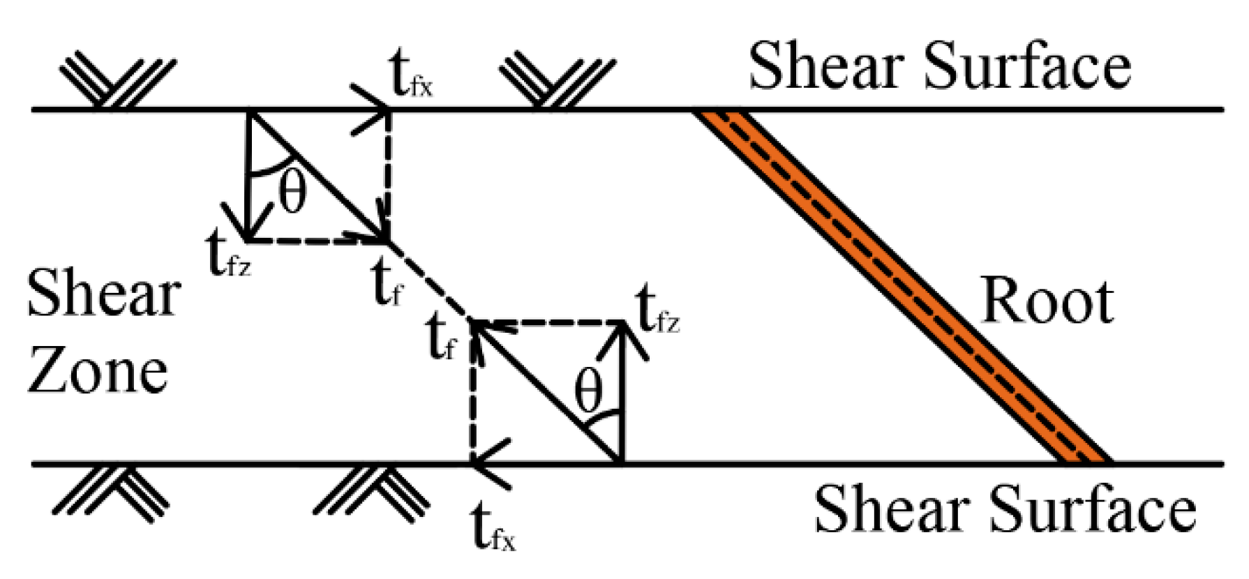
Figure 1. Schematic diagram of Wu’s model (Modified from Wu et al. [31]).
Forests 14 00819 g001
Figure 2. Schematic diagram of fiber bundle model and stress redistribution process (Modified from Pollen and Simon [34]).
Forests 14 00819 g002
Figure 3. Schematic diagram of the displacement-based model (Modified from (Fan, 2012) [32]).
Forests 14 00819 g003
Figure 4. Root growth morphology of Chinese fir.
Forests 14 00819 g004
Figure 5. Particle gradation curve of test soil.
Forests 14 00819 g005
Figure 6. Tensile test of roots.
Forests 14 00819 g006
Figure 7. The sectional structure of Chinese fir root.
Forests 14 00819 g007
Figure 8. Quadruple strain control direct shear apparatus.
Forests 14 00819 g008
Figure 9. Schematic diagram of shear resistance test at root–soil interface.
Forests 14 00819 g009
Figure 10. (a) Organic glass block with root epidermis (b) Test specimen of root–soil interface bond strength after compaction.
Forests 14 00819 g010
Figure 11. Distribution of roots in the shear box.
Forests 14 00819 g011
Figure 12. Preparation of root-permeated soil sample with δ of 90° (RAR0.21% as an example).
Forests 14 00819 g012
Figure 13. Preparation of root-permeated soil sample with δ of 45° (RAR0.21% as an example).
Forests 14 00819 g013
Figure 14. Relationship between shear strength and normal stress of specimen in shear resistance test.
Forests 14 00819 g014
Figure 15. Roots reinforcement Δ τ r of different root-bearing soil samples.
Forests 14 00819 g015
Figure 16. Schematic diagram of a mechanical reinforcement model of soil by root based on interface bonding (a) Root deformation in root-bearing soil (b) Force analysis of root.
Forests 14 00819 g016
Figure 17. Schematic diagram of stress analysis of root–soil interface.
Forests 14 00819 g017
Figure 18. Comparison of measured and calculated values of the root reinforcement.
Forests 14 00819 g018aForests 14 00819 g018b
Figure 19. Comparison between measured values and calculated values of shear strength parameters of root-permeated soil.
Forests 14 00819 g019
Figure 20. Relative orientation of roots and shear surfaces outside the applicable scope of the model (a) The root was parallel to the shear surface; (b) The roots didn’t pass through the soil shear surface; (c) The angle between root and shear direction δ > 90 ° , and the deformation pattern of roots was difficult to identify during shear.
Forests 14 00819 g020aForests 14 00819 g020b
Figure 21. Schematic diagram of δ , α and η angles of roots when the shear direction is inconsistent with the lateral stress direction of soil.
Forests 14 00819 g021
Figure 22. Schematic diagram of roots spatial geometric parameters on a certain depth shear plane.
Forests 14 00819 g022
Table 1. Location and characteristics of Chinese fir.
Geographic LocationAltitude (m)Trunk Diameter (mm)Slope (°)
31°12′33″ N17003607
103°36′31″ E
Table 2. Number of specimens for bond strength of root–soil interface.
Specimen NumberMaterial Composition
Shear Box (Diameter: 61.8 mm; Height: 20 mm)
Top BoxLower Box
RS-ISoilOrganic glass block with root epidermis
SoilSoilSoil
Table 3. Sample number and material parameters of direct shear test with root-bearing soil.
Specimen Numberδ (°)RAR (%)Root Quantity
R2P4450.212
R4P40.424
R6P40.636
R8P40.848
R0P41.0510
R2P9900.212
R4P90.424
R6P90.636
R8P90.848
R0P91.0510
Table 4. Test results of root tensile strength of Chinese fir.
Root Diameter (mm)Tensile Force (N)Tensile Strength (MPa)
238.6812.3
Table 5. Shear strength of specimens under different normal stress in shear resistance test.
Specimen NumberShear Strength (kPa)
σ1 = 25 kPaσ2 = 50 kPaσ3 = 75 kPaσ4 = 100 kPa
Soil28.2434.6444.253.3
RS-I32.843.351.657.7
Table 6. Soil shear strength and root–soil interface bond strength parameters.
Specimen NumberStrength Parameters
Cohesion Stress (kPa)Internal Friction Angle (°)
Soil18.9118.71
RS-I25.118.57
Table 7. Shear strength and strength parameters of root-bearing soil in the direct shear test.
Specimen Number Shear   Strength   of   Root - Permeated   Soil   τ r s ( kPa ) Strength Parameters
σ1
25 kPa
σ2
50 kPa
σ3
75 kPa
σ4
100 kPa
Cohesion Stress
(kPa)
Internal Friction
Angle (°)
R2P429.4836.2646.0755.4519.89 19.33
R4P430.7240.7548.857.3122.44 19.36
R6P432.2941.9750.6859.7523.30 20.08
R8P433.2544.3352.6361.9724.33 20.58
R0P433.5944.9653.1862.0625.36 20.26
R2P928.9235.6745.5654.919.30 19.36
R4P929.4336.1745.9955.6219.73 19.47
R6P930.1737.2247.2656.9920.28 19.90
R8P930.5937.6948.1657.9720.45 20.33
R0P931.0138.1948.6258.4220.88 20.34
Table 8. Model calculation parameters of shear strength of root-permeated soil.
Specimen NumberRAR
(%)
α
(°)
η
(°)
L
(mm)
K0tf
(MPa)
Shear Strength Parameters of SoilBond Strength Parameters of Root–Soil Interface
C
(kPa)
φ
(°)
Crsi
(kPa)
φrsi
(°)
R2P40.214545140.6812.318.9118.7125.118.57
R4P40.424545140.6812.318.9118.7125.118.57
R6P40.634545140.6812.318.9118.7125.118.57
R8P40.844545140.6812.318.9118.7125.118.57
R0P41.054545140.6812.318.9118.7125.118.57
R2P90.21090100.6812.318.9118.7125.118.57
R4P90.42090100.6812.318.9118.7125.118.57
R6P90.63090100.6812.318.9118.7125.118.57
R8P90.84090100.6812.318.9118.7125.118.57
R0P91.05090100.6812.318.9118.7125.118.57
Disclaimer/Publisher’s Note: The statements, opinions and data contained in all publications are solely those of the individual author(s) and contributor(s) and not of MDPI and/or the editor(s). MDPI and/or the editor(s) disclaim responsibility for any injury to people or property resulting from any ideas, methods, instructions or products referred to in the content.