Abstract
Agrotechnological procedures related to forest management, including planting, are burdensome and the energy expenditure of the people working is very high. Nowadays, planting is usually carried out manually, and sometimes with the use of planters coupled to universal tractors. Occasionally, planters mounted on high-power carriers are used, and usually the seedlings are removed from their cassettes and placed manually into the planter’s storage unit. In connection with the above, the prototype of a mobile automatic device for performing forest regeneration tasks and afforestation of post-agricultural and reclaimed areas (RoboFoR) was designed. The main task of this vehicle is planting forest tree seedlings with a covered root system, which are collected directly from their nursery cassettes. This study presents the structure, principle of operation and results of operational tests of the seedling storage and feeding unit. It was found that the unit achieved the expected work efficiency. However, imperfections in the system related to the non-centralized distribution of seedlings in containers and the high variability of biometric characteristics of the seedlings were also identified. A new solution for this unit was proposed, which will increase the reliability of collecting the seedlings. A new solution requires greater computational power of the control unit as well as equipping the sensor system with a technologically advanced root neck detection system. The new concept also assumes the possibility of independent movement of each gripper.
1. Introduction
The problems and challenges of modern agriculture [1] can be largely identified as present also in forestry [2,3]. The most important one is the necessity to meet the needs of the Earth’s growing population for wood, used to produce consumer goods, such as paper, furniture, construction materials, etc. Further needs are related to the necessity to introduce principles of sustainable forest production that will ensure the safety of forest workers, support environmental balance and guarantee the above-mentioned sufficient level of productivity [4]. The implementation of these principles is best achieved by introducing automatic machines in forestry production [5], especially for those tasks that require manual labor—including planting, which is characterized by a high energy input [6,7,8]. These solutions will also reduce many other problems of modern forestry: low unemployment and, therefore, a limited number of workers available on the market (especially in the case of monotonous and tedious seasonal tasks, performed in the open terrain, often in unfavorable weather conditions (heat waves and rain)). These factors result in a reluctance to take on this type of work [9,10].
Based on the analysis of devices and machines used for tree planting [11,12,13], it can be concluded that what are mostly used for this purpose are simple manual devices and classic planters attached to agricultural tractors that need human operators. There are also a few machines that offer a certain range of planting automation, especially in the aspect of planting forest tree seedlings with a covered root system. However, these are devices that still require a significant amount of manual operation [14,15,16,17]. This work involves manually transferring seedlings from containers to appropriate storage units, from which the seedlings are next collected by automatic systems that then plant them into the soil. These structures are modelled on existing solutions for vegetable planters—cabbage, celery, lettuce, etc. [18,19,20]—this is due to the fact that the seedlings of these vegetables are similar to tree seedlings. The difference is only due to their size. These devices are usually attached to agricultural tractors or are adapters attached to construction excavators, which makes them heavy and relatively inefficient [13].
For the above reasons, we have designed the prototype of a mobile automatic device for forest regeneration and afforestation of post-agricultural and reclaimed areas—RoboFoR (Figure 1). The main task of this vehicle is to plant forest tree seedlings with a covered root system (grown in container nurseries) that are collected directly from nursery cassettes [21].
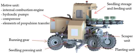
Figure 1.
Diagram of the RoboFoR mobile automatic device for planting forest trees with a covered root system.
The concept of the vehicle’s construction, its technical parameters and its general method of operation have already been discussed in many studies [12,21]. This article is focused only on one of the vehicle’s components: the seedling storage and feeding unit.
2. Seedling Storage and Feeding Unit: Design Assumptions and Basic Research
The planting efficiency of the planting unit is determined by the efficiency of feeding the seedlings into it. Assuming the maximum planting efficiency, i.e., every 0.5 m, and the vehicle speed of 1.5 km/h, the time needed to plant one seedling is 1.2 s. However, this is a case of maximum efficiency, while sufficient (normal) efficiency means planting seedlings with the spacing of 0.9 m and the vehicle speed of 1 km/h, as a result of which the time needed to plant one seedling is 3.2 s [12,21]. It was assumed that seedlings would be fed directly from two types of nursery cassettes, differing in the number of cells (28 or 40 cells) and the height (120 or 150 mm) of each of them (Figure 2a). With the assumed efficiency and the minimum distance of 200 m for which there must be enough seedlings until the cassettes can be replaced, the minimum storage capacity was determined as 15 cassettes.
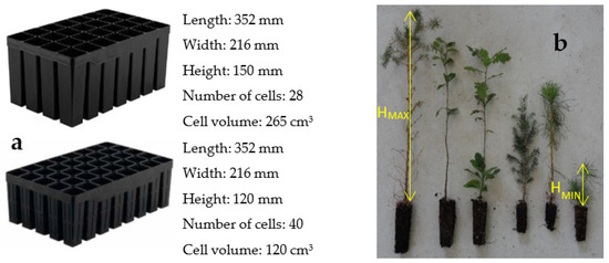
Figure 2.
Assumptions regarding the method of collecting seedlings: (a) parameters of the cassettes from which the seedlings are collected; (b) seedling parameters.
Among the biometric features determined for seedlings (Figure 2b) were the minimum and maximum height of the seedling and the diameter of the root collar. These parameters, especially the height of the seedling, depend very strongly on the tree species. Coniferous tree seedlings are usually much shorter and more frail than deciduous tree seedlings. Depending on the tree species, the height of the seedlings used during the research ranged from approximately 0.08 m for pine and spruce to approximately 0.6 m for beech and oak. An equally, if not more, important parameter of the seedlings is the size of the root collar diameter, i.e., the place where the automatic collection unit will clamp on the seedlings to pull them out. In this case, for the tested coniferous seedlings, the average value was between 2.99 mm (spruce) and 3.68 mm (pine). The minimum value of 1.84 mm was recorded for a pine seedling, and the maximum value of 5.04 mm was also recorded for a pine seedling. For deciduous trees, the value was between 4.57 mm (beech) and 6.44 (oak). In the case of deciduous species, the thinnest root collar (2.45 mm) was measured in beech trees, and the thickest (8.73 mm) in oak seedlings.
In order to select the right elements that will clamp on the root collar of the seedlings and enable them to be pulled out of the nursery cassette, tests were carried out on the force needed to perform this activity [22]. The force was measured on a computerized station with a Shimadzu AGX-V testing machine (Figure 3a) and using a manual Axis FC200 dynamometer (Figure 3b) (Table 1).

Figure 3.
Measurement of the force necessary to pull a seedling out of its container: (a) Shimadzu AGX-V universal testing machine; (b) manual Axis FC 200 dynamometer.

Table 1.
Results of measurements of forces (N) necessary to pull seedlings out of nursery cassettes.
The greatest variation in forces occurred for deciduous tree seedlings, and in particular for oak. This is related to seedling size; in the case of deciduous trees, they are much larger and therefore more diverse from each other. For this reason and because of the greater height of the cassettes, there are also greater forces needed to pull the seedling with the root ball out of the cassette cell, compared to coniferous seedlings. These differences were not large and did not exceed 20 N, which allows for concluding that no large forces are required to pull the seedlings out of their cassette cells. This also affects the condition of the root collar, the damage of which could disqualify the developed RoboFoR robot solution.
The highest value of the pulling force was determined for oak seedlings, which was 18.84 N. Two grippers were selected, the P7K20 angle gripper made by Metal Work and the MHK2-20D parallel gripper produced by SMC (Figure 4), for which tests were carried out to measure the holding force of a seedling. The tests were performed on a universal testing machine (Material Testing Machine) of type HT-2402 (Figure 5a). The seedlings, in accordance with the guidelines contained in the principles of silviculture, were held by the root collar gripper directly above the root ball using specially profiled and rubberized gripping tips (Figure 5b). A seedling’s root ball was immobilized in its lower holder, then an attempt was made to pull the seedling out by means of the vertical movement (at a speed of 2 m/min) of the upper handle of the machine, in which the gripper was mounted. The test was carried out until the seedling moved longitudinally in the gripping tip, i.e., until the adhesion force between these elements was broken.
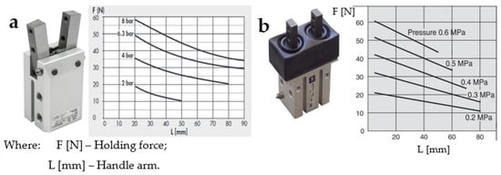
Figure 4.
Grippers with their operating characteristics: (a) P7K20 Metal Work angle gripper; (b) SMC MHK2-20D parallel gripper.
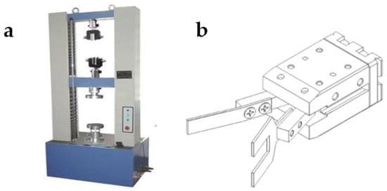
Figure 5.
Holding force test stand: (a) universal testing machine, type HT-2402; (b) angle gripper model with gripping tips attached.
In the case of the angular gripper, the maximum values of the force holding the seedling reached 20 N (Figure 6a). In the case of the parallel gripper, which was characterized by an additional gear ratio, the measured seedling holding forces were higher and reached up to 50 N (Figure 6b). In the case of the parallel gripper, despite much higher holding forces, the working range—i.e., the maximum possibility of spreading the gripping arms—allowed for gripping only a seedling that grew in the central part of the cassette cell. The angular positioning of the arms in the angular gripper allowed it to collect seedlings from the entire surface of the cell in a nursery cassette. This aspect determined the choice of this gripper as the basis for developing a seedling storage and feeding unit.
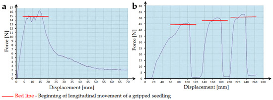
Figure 6.
The course of the seedling holding force for the tested types of grippers: (a) angle gripper; (b) parallel gripper.
Subsequent research focused on identifying the maximum accelerations to which seedlings may be exposed when being manipulated, so as not to destroy them. By forcing the human hand to move (Figure 7) along a horizontal line delineated with markers (white dots in black circles), various acceleration/deceleration values were obtained. The movement of the seedlings was recorded with a special camera at 250 frames per second, which enabled easy determination of the path covered in a given unit of time. On this basis, the accelerations affecting the seedlings were determined, which ranged from 15 to 30 m/s2.
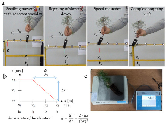
Figure 7.
Tests of the acceleration acting on the seedlings: (a) subsequent moments while the seedling movement was slowing down; (b) method of determining acceleration; (c) measurement of the mass loss in the soil lump.
After carrying out the tests, it was found that the registered dynamic overloads caused by the accelerations achieved during the tests did not cause any significant damage to the root balls (loss of the root ball < 2% of its volume).
3. Seedling Storage and Feeding Unit—Structure and Principle of Operation
The basic research and work cycle analyses performed allowed for the selection of specific executive elements in the form of ready-made purchased components (actuators, grippers, motors, etc.). This, on the basis of the developed solution concepts and the selection of one of them, enabled the final design of the storage and feeding unit (Figure 8). This unit is located in the front upper part of the vehicle and consists of three main components: a rotating table—a nursery cassette storage unit (Figure 9), a unit for collecting seedlings out of their cassettes and a buffer unit.
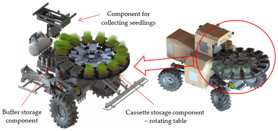
Figure 8.
Construction of the RoboFoR vehicle’s seedling storage and feeding unit.
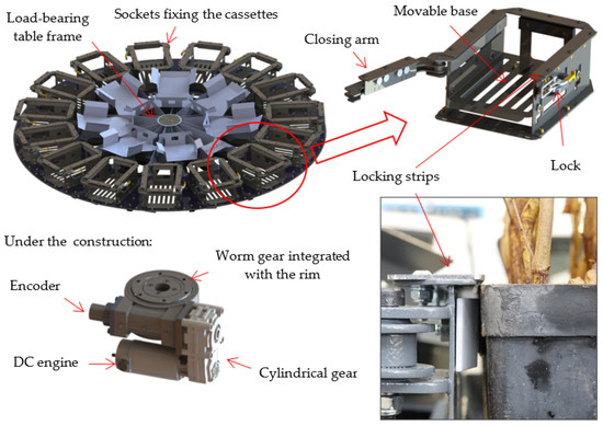
Figure 9.
Structure of the rotating table—nursery cassette storage component.
The largest spatial element of the seedling storage and feeding unit is the rotating table, which is simultaneously a storage component and a cassette feeder. Due to the difference in height of the cassettes selected for use in the mobile device, the developed positioning socket is equipped with a movable base so as to be able to position both types of cassettes in the desired place. This element has been designed in such a way that, using sliding guides and appropriately adapted guide paths, the height of the socket base is changed, adapting it to the height of the nursery cassettes. The use of a manual locking system in the form of a closing arm and a lock allows users to easily and quickly remove empty cassettes and replace them with ones filled with seedlings (Figure 10). The upper locking strips support the cassettes to prevent them from being lifted up together with the extracted seedlings. The drive of the rotating table is located underneath in its central part and is composed of a DC motor and two gear types, the cylindrical and the worm gear, whose combined ratio allows for a significant reduction in rotational speed.
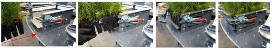
Figure 10.
Process of replacing cassette.
The main function of the seedling collection unit (Figure 11) is to lift their entire row from the nursery cassette fixed in the fixing socket of the rotating table. Next, feed the collected seedlings to a buffer conveyor whose spacing of pipes, i.e., transfer channels, is much larger than a cassette cell. The seedlings grabbed by the gripper arms are lifted to a height that allows the entire root ball to be pulled out above the immobilized cassette. Seedlings pulled out of the cassette by the gripper component are transferred to the channels of the buffer unit using appropriate actuators of the linear motion component (the most important of them is the spindle axis). During this movement on the path between the cassette and the buffer unit, the grippers with the captured seedlings are moved apart to the required distances equal to the spacing of the buffer channels. Appropriately spaced grippers with the seedlings are docked for a moment above the empty buffer channels and when the grip is released, the seedlings fall by gravity into the empty buffer channels. Sequences of the operation of the seedling collection unit are visualized in Figure 12.
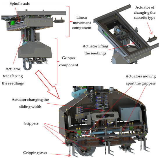
Figure 11.
Structure of the seedling collection unit.
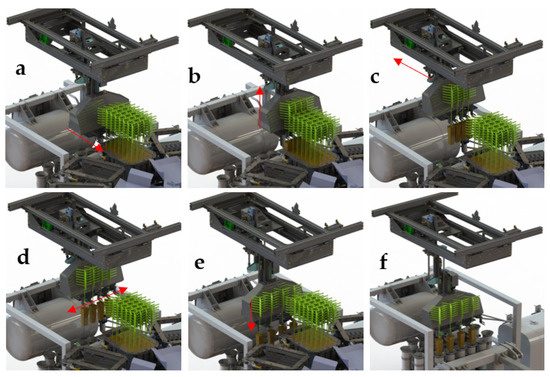
Figure 12.
Sequence of operation of the seedling collection unit—approach to the first row of seedlings: (a) movement of the spindle axis to the position of a specific row of seedlings; (b) reaching a position above a given row, tightening the grippers on the root necks of the seedlings and then pulling them out of the cassettes; (c) movement of the spindle axis to the position of seedling release into the buffer channel; (d) moving the grippers apart (conducted at the same time as point c); (e) lowering the gripper component; (f) releasing the seedlings by the grippers.
Assume the high efficiency of the seedling collection unit, and therefore very high dynamics of the gripping unit. Also, take into account the limited possibilities of developing this component—rows of grippers as close to each other as possible and grip the seedling as low as possible at the root ball. It was necessary to develop a gripping unit (Figure 13) with the smallest possible weight and dimensions. Such assumptions necessitated the use of the minimum possible number of drive elements in the form of light pneumatic actuators. Due to the need to pull seedlings out of two types of nursery cassettes, the seedling collection unit has the function of automatic conversion to a given cassette type. One type of cassette (type I) contains seedlings of deciduous trees, while the other one (type II) involves coniferous trees, which is related to root system size to cell height. For this reason, the gripper component, consisting of five grippers working in one block, was developed to collect seedlings from cassettes with five rows of cells. To collect seedlings from cassettes with four rows of cells, the rightmost gripper performs idle movement. The operating principle of the gripper component is based on the use of purchased gripper modules to which specially designed gripping arms covered with rubber are attached. Due to the specific dimensions of the grippers and the limited installation area, it was necessary to place the grippers in two rows: three grippers in the upper row and two grippers in the lower row. By appropriately mounting each of the four grippers on the running plate unit, to which two trolleys moving on the guide rails are attached, they can be moved laterally. One of the grippers used in the construction of this assembly (the top central one) is permanently attached to support plate 1 and support plate 2. Connecting the trolleys (the upper and the lower row) of the grippers on the left and right sides, respectively, with each other, using springs and pushers of this unit component, it is possible to move the grippers apart using two pneumatic actuators. Additionally, by using a special blockage activated using an actuator, it is possible to achieve three positions of mutual separation of the grippers (Figure 14).
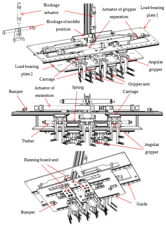
Figure 13.
Structure of the gripper unit.
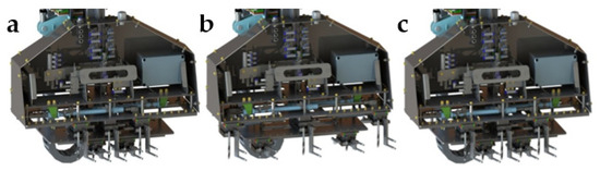
Figure 14.
Spacing of grippers depending on the activity being performed: (a) grippers pushed together to pick up seedlings from a cassette with 5 seedlings in a row; (b) extending the grippers for the release of seedlings into the buffer storage; (c) grippers pushed together to pick up seedlings from a cassette with 4 seedlings in a row.
After the seedlings reach the appropriate channels of the buffer unit (Figure 15), due to the forced impulse movement of this carrier, they move along the slide plate toward the inlet to the dibble pipe, over which subsequent seedlings fall by gravity. The movement of the channels attached to chains mounted on wheels coupled to the shafts is carried out using the DC gear motor. The empty buffer channel continues its elliptical loop path to the point of refilling.
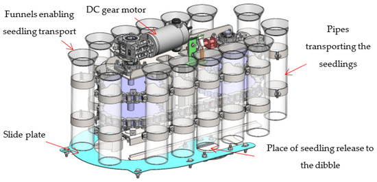
Figure 15.
Structure of the buffer unit.
The entire structure of the seedling storage and feeding unit works in an open control system. This means that the controller, through appropriate elements (coils/valves, relays) controlling the executive elements, causes the movement of seedlings to predetermined positions signaled with limit sensors or encoders.
The method of solving the construction of the entire seedling storage and feeding unit and the gripper component itself is subject to two patent applications (P.439795, P.440312), which contain a more detailed description of their operation.
4. Site and Field Tests of Seedling Manipulation
As an automated device operating in an open control system, the seedling storage and feeding unit performs working movements according to a strictly defined pattern. Therefore, it is very important to precisely determine the duration of subsequent working movements of the actuating elements in order to determine the actual efficiency of feeding the seedlings. The rotating table moves by an angle of 24°, which results from collecting the seedlings from subsequent cassettes. The buffer conveyor at a distance of approx. 102 mm results from the arrangement of subsequent channels. Due to short movement distances and relatively high power of the selected drive elements, neither the cassette storage component nor the buffer component causes any problems related to failure to achieve the expected work efficiency. Additionally, these units work independently of the seedling collection unit, i.e., when this component is transporting the seedlings in the air. The bottleneck of the entire seedling manipulation system is the seedling collection component. Due to the greater complexity of its structure and the greater movement distances of the actuating elements, it requires much more time to complete these movements in a single work sequence (collection of the entire row of seedlings). In the case of this component, such a sequence includes the previously mentioned working movements (Figure 12), combining into one complete working cycle. The cassette is located at a fixed distance from the starting line of 190 mm, while subsequent rows of seedlings are spaced at a certain distance equal to the cassette’s graduation. For type I cassettes, this is 50 mm, and for type II, it is 44 mm, which turns into a similar distance in the case of collection from the first row: 215 mm for type I and 210 mm for type II. Assuming the average linear speed of movement of the gripping unit as equal to 300 mm/s, the time needed to perform this working movement increases (Table 2). This is due to the need to collect subsequent rows of seedlings placed at an increasing distance from the starting line (Figure 16 and Figure 17). For the last row of seedlings, this distance is approximately 515 mm for type I and 518 mm for type II.
Table 2.
Results of measurements of the time necessary to remove seedlings from nursery cassettes.
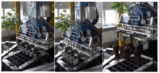
Figure 16.
Tests of collecting deciduous tree seedlings from the last row of a type I cassette.
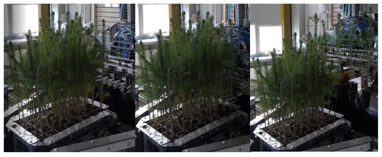
Figure 17.
Tests of collecting coniferous tree seedlings from the first row of a type II cassette.
The operation of the gripping unit in the automatic mode runs correctly and without major interruptions affecting the operation of the entire mobile planting machine if the seedlings are properly grown. A seedling with a straight root neck, growing straight up and growing in the center of its cell in the cassette, is considered to be grown properly. Due to the design and principle of operation of the gripper and its fingers, correct collection of a seedling is possible when it grows within a radius of 1.5 cm from the center of the cassette cell. However, if it grows near the side of a cell, as shown, e.g., in Figure 18b, then the gripper fingers will not be able to catch such a seedling properly or at all. This causes a disturbance in the process, which may take various forms depending on the cause. Problematic seedlings are unlikely to occur in the case of coniferous trees. This is related to the automation of the planting process and, what is equally important, to the small size of their seeds. The size of the seeds facilitates the automation of planting in container nurseries and, above all, allows seeds to be placed each in the center of its cell. Also, the smaller height of coniferous seedlings makes them much less susceptible to tilting during growth. As can be seen in Figure 18, the problem of seedlings growing near the walls of the cassette cell concerns mainly deciduous trees. Deciduous tree seedlings grow faster, are taller and are therefore more susceptible to external influences, e.g., tilting by the wind when grown in forest nurseries in containers placed in open beds in the open air. Of course, no one can influence the occurrence of such extreme situations as shown in Figure 18c. In order to prevent this type of situation and ensure proper operation of the device in question over the longest possible time intervals, it was assumed that seedlings will be controlled by people handling the planting process [11]. If seedlings with an incorrect structure or appearance are detected in the cassettes prepared for placing in the nests on the feeding table, they will be manually removed from the cells and replaced by ones with appropriate external characteristics. This is consistent with the previously mentioned principles of forest tree planting, according to which only seedlings with straight shoots should be planted so as to ensure obtaining high-quality timber [23].
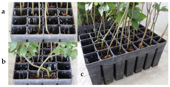
Figure 18.
Atypically grown seedlings—problematic to pick up with grippers: (a)—seedlings with root collars located too close to each other; (b)—seedlings overlapping subsequent cassette cells located in the same row; (c)—seedlings overlapping subsequent cassette cells located in the next row.
If a seedling or seedlings grow in a way that prevents them from being picked up by the gripper’s fingers, then, after placing the collected seedlings in the channels of the buffer unit, a second attempt will be made to collect the remaining seedling or seedlings. In the event of another failure, the entire RoboFoR device will stop working, during which the operator will be forced to remove the uncollected seedlings from the cassette cells. This approach significantly reduces the efficiency of the planting machine.
5. New Concept of Operation
The presented structure has an open control system (Figure 19) operating in accordance with the developed algorithm. This means that the element controlling its operation does not receive any information about the output signal y, but has a specific control goal represented by the set value y0. The set value is the extreme position of specific executive elements (e.g., the actuators extending the grippers, the actuator pulling out seedlings, the actuator lowering the gripping unit, etc.) signaled with binary sensors. In the case of movement of the spindle axis, set values are at specific positions relative to the declared reference position.
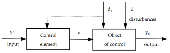
Figure 19.
General diagram of the open control system for the seedling feeding component.
The main control element is the controller (integrated microprocessor system), which sends the control signal u through appropriate outputs to specific control objects (pneumatic solenoid valve coils, relay coil). Through the force generated by the coil acting on the piston inside the electrovalve, the pneumatic working medium is appropriately controlled and supplies the appropriate chamber of a given pneumatic actuator, making it move. In the case of the spindle axis motor, short-circuiting the circuit inside the relay close to the power supply circuit makes it move.
The existing control concept, which uses special sockets to precisely position nursery cassettes, guarantees trouble-free operation of the developed seedling storage and retrieval system, but only in the case of collecting seedlings that grow vertically in the central part of the cells. Therefore, to ensure seedling collection reliability, it is necessary to use a different approach to the operation of this unit.
The new concept of collecting seedlings assumes the implementation of an additional non-contact measuring element, identifying the location of the root necks of successively collected rows of seedlings from a given nursery cassette. It is also necessary to modify the gripper unit by equipping the grippers with an independent intermediate drive that allows each gripper to move in a continuous range of motion along the x (±20 mm) and y (±15 mm) axes. The central gripper should also have smooth position adjustment along these axes, and this movement can be implemented in a different place. In the x axis, replacing the binary actuator in terms of changing the cassette type with a drive enables continuous movement. In the y axis, this movement can be performed using the spindle axis. Such a concept of adjusting the position of the grippers (Figure 20) would require significant intervention in the control algorithm of this system. This algorithm would use information about the position of the seedling root necks and thus determine the best possible position of the grippers when collecting a specific row of seedlings. If these seedlings were transferred to the buffer unit, the principle of operation would remain unchanged.
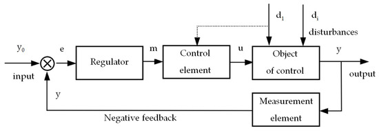
Figure 20.
General diagram of the closed seedling feeding component control system.
To confirm the validity of the new concept of seedling collection, laboratory tests were carried out (Figure 21) involving the detection of the exact location of seedling root necks using the ATOS II contactless measurement system. The Atos II optical scanner is a device operating on the principle of white light (electromagnetic wave with a wavelength in the range of 380–780 nm). The scanner projects a set of fringes onto the surface of the examined object and observes their distortion on this uneven surface through two cameras placed on both sides of the projector (Figure 22A). The cameras are mounted on a common beam together with the projector, defining the base of the triangle. The vertices of this triangle are constituted by a point on the plane (projected from the projector) and the observation cameras that measure the angle at which a given point is visible (Figure 22B) [24,25]. By analyzing the radiation beams of the waves sent and received (by measuring the delay between sending and receiving the signal) and by using relatively simple geometric relationships, it is possible to determine the coordinates of subsequent points in the Cartesian system (X, Y, Z), as a result of which it is possible to identify a set of such points (the so-called point cloud). The number of scans depends on the complexity and dimensions of the measured detail. The complete cloud contains from a few to several dozen million points, enabling measurement of the surface shape with an accuracy depending on the lenses installed in the scanner. In the final measurement stage, the point cloud is polygonized—it is turned into a proper surface. Individual measured points are connected to each other to form a triangle mesh. This is the so-called STL (Stereolithography)—a standard format for exchanging 3D CAD data in areas of industry related to, among others, rapid prototyping. Thanks to the use of this technology, it is possible to simultaneously scan the entire available surface of the object.
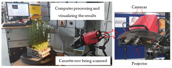
Figure 21.
Tests consisting in scanning the root collars of seedlings collected from successive cell rows.
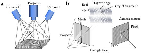
Figure 22.
Principle of operation of the ATOS II scanner [25]: (a)—dual camera scanning for improved scanning accuracy; (b)—application of the triangulation principle in 3D scanning.
Using the obtained three-dimensional digital image of three subsequent rows of seedlings (Figure 23), further dimensional analyses were carried out, consisting in determination of the diameter and center of the root collar of a given seedling. By comparing the coordinates of the root collar center obtained, averaged from four samples (four heights), with the coordinates of the cell centers of a given cassette (Figure 24), it is possible to determine the set/input values of the position of a specific gripper.
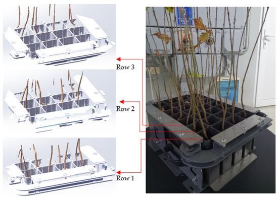
Figure 23.
Scanning results of the first 3 rows of a type II cassette.
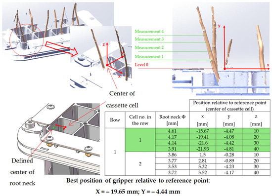
Figure 24.
Method of determining the position of the center of the root collar in 1 cell of row 1.
6. Conclusions
The existing research presents the seedling storage and feeding unit, which is part of an automatically controlled planting forest machine—“RoboFoR”. Investing in forestry is crucial due to the importance of forests in life on the Earth. The current machine is a prototype to serve this sector. It can fulfill the need and suit people especially in developed countries in which there is a shortage of employees.
The current solution of this unit has confirmed the correctness of the developed project through operational tests and achievement of the assumed operation efficiency. The efficiency of feeding one seedling into the planter’s block, depending on the row of seedlings taken, varies from 1.66 to 3 s. However, due to certain imperfections of this system, situations of incorrect operation do occur. In such a situation, productivity drops dramatically.
The new solution concept for this unit presented in the article will certainly increase the reliability of seedling collection. It is also much more high-tech, requiring a much more powerful control unit in terms of computing power and additionally equipping the sensor system with a technologically advanced root neck detection system. The new concept also assumes the possibility of independent movement of each gripper, within a certain continuous range of displacement in two directions by servo drives. As a result, the cost of modifying this unit can be up to several times the price of making the existing version.
Precise collection of seedlings also makes it possible to use another type of gripper, with parallel jaw clamping motion. Parallel grippers are characterized by a smaller jaw clamping stroke, but with the ability to generate more force with a comparable overall size to angle grippers. This situation will make it possible to use a smaller type of gripper, which will also make it possible to distribute them in one level in the gripper assembly.
The scanning tests presented in the article were also carried out for coniferous seedlings, whose root collars are more covered with suckers. The solution concept was confirmed also in this case.
If the consortium and the General Directorate of the State Forests in Poland decide to continue this project, it will be necessary to use some kind of industrial, weatherproof mobile solution of a ToF sensor with an integrated vision sensor to achieve the best efficiency [26,27,28]. It would also be desirable to develop a system that feeds seedlings with an exposed root system.
7. Patents
The solutions presented in the study were registered in the Patent Office of the Republic of Poland:
- (1)
- Sobocki S., Mac J., Szychta M., Wąchalski G., Danielak M., Wojciechowski J., Adamczyk F., Tylek P., Walczyk J., Szewczyk G., Kormanek M., Kiełbasa P. Zgłoszenie patentowe nr P.439795 z dn. 9.12.2021 na wynalazek pt. Zautomatyzowany zespół magazynująco-pobierający sadzonki, zwłaszcza mobilnego automatu do sadzenia drzew z zakrytym systemem korzeniowym.
- (2)
- Sobocki S., Mac J., Wąchalski G., Adamczyk F., Wojciechowski J., Szychta M., Zwierzyński M., Kaźmierczak M., Tylek P., Kormanek M. Zgłoszenie patentowe nr P.440312 z dn. 7.02.2022 na wynalazek pt. Zespół chwytaków manipulatora, zwłaszcza układu pobierającego sadzonki mobilnego automatu do sadzenia drzew.
Author Contributions
Conceptualization, S.S., F.A., M.S. and P.T.; methodology, S.S., K.Ż., J.M., P.T. and M.K. (Mariusz Kormanek); software, M.Z. and M.K. (Michał Kaźmierczak); validation, M.S., J.M. and M.K. (Mariusz Kormanek); formal analysis, S.S.; investigation, F.A., K.Ż. and G.S.; resources, M.S. and G.S.; data curation, P.T., S.T., F.A. and S.S.; writing—original draft preparation, S.S., F.A., P.T. and K.Ż.; writing—review and editing, S.T. and G.S.; visualization, S.S., M.Z., M.K. (Michał Kaźmierczak) and P.T.; supervision, M.S. and S.T.; project administration, P.T., M.S. and F.A.; funding acquisition, P.T., S.T. and F.A. All authors have read and agreed to the published version of the manuscript.
Funding
The research is part of the project entitled “A mobile automatic device for forest regeneration tasks and afforestation of former farmland and reclaimed areas (RoboFoR)”, No. EO.271.3.11.2019. The project has been financed by the General Directorate of State Forests in Warsaw. The research was also carried out under the Implementation Doctorate Program of the Ministry of Education and Science implemented in 2020–2024 (Agreement No. DWD/4/22/2020).
Institutional Review Board Statement
Not applicable.
Informed Consent Statement
Not applicable.
Data Availability Statement
Data supporting this study may be provided on request by the first author of the study.
Conflicts of Interest
The authors declare no conflict of interest.
References
- Sobocki, S.; Wojciechowski, J.; Legutko, S.; Mac, J.; Zawada, M.; Szymczyk, S. Field robots development in the aspect of achieving the goals of sustainable agriculture. In IOP Conference Series: Materials Science and Engineering, The 25th Edition of IManEE 2021 International Conference (IMANEE 2021), Online, 21–22 October 2021; IOP Publishing: Bristol, UK, 2021; Volume 1235. [Google Scholar] [CrossRef]
- Angelstam, P.; Bush, T.; Manton, M. Challenges and Solutions for Forest Biodiversity Conservation in Sweden: Assessment of Policy, Implementation Outputs, and Consequences. Land 2023, 12, 1098. [Google Scholar] [CrossRef]
- Pan, C.; Li, C.; An, A.; Deng, G.; Lin, J.K.; He, J.; Li, J.F.; Zhu, X.; Zhou, G.; Shrestha, A.K.; et al. Canada’s Green Gold: Unveiling Challenges, Opportunities, and Pathways for Sustainable Forestry Offsets. Forests 2023, 14, 2206. [Google Scholar] [CrossRef]
- Chirici, G.; Giannetti, F.; D’Amico, G.; Vangi, E.; Francini, S.; Borghi, C.; Corona, P.; Travaglini, D. Robotics in Forest Inventories: SPOT’s First Steps. Forests 2023, 14, 2170. [Google Scholar] [CrossRef]
- Bernadzki, E. Opracowanie zbiorowe pod redakcją Eugeniusza Bernadzkiego. In Lasy i Leśnictwo Krajów Unii Europejskiej (Forests and Forestry of the European Union); CILP: Warszawa, Polska, 2006. [Google Scholar]
- Shamshiri, R.R.; Weltzien, C.; Hameed, I.A.; Yule, I.J.; Grift, T.E.; Balasundram, S.K.; Pitonakova, L.; Ahmad, D.; Chowdhary, G. Research and development in agricultural robotics: A perspective of digital farming. Int. J. Agric. Biol. Eng. 2018, 11, 1–14. [Google Scholar] [CrossRef]
- Schnorf, V.; Trutnevyte, E.; Bowman, G.; Burg, V. Biomass transport for energy: Cost, energy and CO2 performance of forest wood and manure transport chains in Switzerland. J. Clean. Prod. 2021, 293, 125971. [Google Scholar] [CrossRef]
- Okuda, M.; Kawamoto, Y.; Tado, H.; Fujita, Y.; Inomata, Y. Energy Expenditure Estimation for Forestry Workers Moving on Flat and Inclined Ground. Forests 2023, 14, 1038. [Google Scholar] [CrossRef]
- Yilmaz, R.; Kayacan, Y. A study on determining the physical workload of the forest harvesting and nursery-afforestation workers. Anthropology 2015, 21, 168–181. [Google Scholar] [CrossRef]
- Šporčić, M.; Landekić, M.; Šušnjar, M.; Pandur, Z.; Bačić, M.; Mijoč, D. Deliberations of Forestry Workers on Current Challenges and Future Perspectives on Their Profession—A Case Study from Bosnia and Herzegovina. Forests 2023, 14, 817. [Google Scholar] [CrossRef]
- Więsik, J.; Aniszewska, M. Urządzenia Techniczne w Produkcji Leśnej. T. 1. Urządzenia do Hodowli i Ochrony Lasu (Technological Devices in Forest Production. Vol. 1. Devices for Silviculture and Forest Protection); Wydawnictwo SGGW: Warszawa, Polska, 2011; ISBN 978-83-7583-219-8. [Google Scholar]
- Adamczyk, F.; Szychta, M.; Wojciechowski, J.; Danielak, M.; Sobocki, S.; Szaroleta, M.; Kapela, D.; Szulc, T.; Tylek, P.; Walczyk, J.; et al. Automatyzacja Procesu Sadzenia Drzew Leśnych z Zakrytym Systemem Korzeniowym na Przykładzie Modelu Badawczego Automatycznego Robota do Zakładania Upraw Leśnych; Technika Rolnicza, Ogrodnicza, Leśna: Poznań, Poland, 2022; pp. 25–30. ISSN 1732-1719. [Google Scholar]
- Ersson, B.T. Concepts for Mechanized Tree Planting in Southern Sweden; Faculty of Forest Sciences, Department of Forest Biomaterials and Technology, Swedish University of Agricultural Sciences: Umeå, Sweden, 2014; ISSN 1401-1204. [Google Scholar]
- Ersson, B.T.; Bergsten, U.; Lindroos, O. Reloading mechanized tree planting devices faster using a seedling tray carousel. Silva Fenn. 2014, 48, 1064. [Google Scholar] [CrossRef]
- Johnston, K.; Cheung, I.C.; Henderson, F.; Queen, G.; Lida, K. Enhancement of Forestry Tree Planting Machine; ME519 Group Project 2016; Mechanical and Aerospace Engineering, University of Strathclyde: Glasgow, UK, 2016. [Google Scholar]
- Laine, T. Mechanized Tree Planting in Finland and Improving its Productivity; Dissertationes Forestales 2017, no 237; Department of Forest Sciences, Faculty of Agriculture and Forestry, University of Helsinki: Helsinki, Finland, 2017. [Google Scholar] [CrossRef]
- Zhu, B.; Liu, J.; Yang, C.; Qu, W.; Ding, P. Power Compensation Strategy and Experiment of Large Seedling Tree Planter Based on Energy Storage Flywheel. Forests 2023, 14, 1039. [Google Scholar] [CrossRef]
- Amer, M.; Yahya, A.; Daraghmeh, A.; Dwaikat, R.; Nouri, B. Design and Development of an Automatic Controlled Planting Machine for Agriculture in Palestine. Univers. J. Control Autom. 2020, 8, 32–39. [Google Scholar] [CrossRef]
- Zeng, F.; Li, X.; Bai, H.; Cui, J.; Liu, X.; Zhang, Y. Experimental Research and Analysis of Soil Disturbance Behavior during the Hole Drilling Process of a Hanging-Cup Transplanter by DEM. Processes 2023, 11, 600. [Google Scholar] [CrossRef]
- Zhang, J.; Niu, Z.; Li, T.; Wu, Y.; Xi, R.; Li, Y.; Li, G.; Hou, J. Design and Optimization of Planting Process Parameters for 2ZYX-2 TypeGreen Onion Ditching and Transplanting Machine. Phyton-Int. J. Exp. Bot. 2020, 89, 147–166. [Google Scholar] [CrossRef]
- Tadeusiewicz, R.; Tylek, P.; Adamczyk, F.; Pietrzykowski, M.; Szewczyk, G.; Szychta, M.; Kiełbasa, P.; Sobocki, S.; Danielak, M.; Juliszewski, T.; et al. RoboFoR—Automat do sadzenia drzew. Podstawowe moduły i właściwości funkcjonalne. Nauka Tech. Technol. 2022, 6, 119–136. [Google Scholar] [CrossRef]
- Tylek, P.; Walczyk, J.; Mateusiak, Ł. Szkółkarska wyciskarka sadzonek z kaset styropianowych. Tech. Rol. Ogrod. Leśna 2020, 2, 2–4. [Google Scholar]
- Haze, M.; Widłąszewska, B.; Jędrasik, B. Zasady Hodowli Lasu; Ośrodek Rozwojowo-Wdrożeniowy Lasów Państwowych w Bedoniu 2012; Państwowe Gospodarstwo Leśne Lasy Państwowe: Warszawa, Poland, 2012; ISBN 978-83-61633-65-5. [Google Scholar]
- Milde, J.; Dubnicka, M.; Buransky, I. Impact of powder coating types on dimensional accuracy in optical 3d scanning process. MM Sci. J. 2023, 6800–6806. [Google Scholar] [CrossRef]
- Karczewski, M.; Koliński, K.; Walentynowicz, J. Wykorzystanie skanera 3D do analizy uszkodzeń silników spalinowych. Zesz. Nauk. Akad. Mar. Wojennej 2011, 52, 59–66. [Google Scholar]
- Tsoulias, N.; Paraforos, D.S.; Fountas, S.; Zude-Sasse, M. Estimating Canopy Parameters Based on the Stem Position in Apple Trees Using a 2D LiDAR. Agronomy 2019, 9, 740. [Google Scholar] [CrossRef]
- Gené-Mola, J.; Sanz-Cortiella, R.; Rosell-Polo, J.R.; Escolà, A.; Gregorio, E. In-field apple size estimation using photogrammetry-derived 3D point clouds: Comparison of 4 different methods considering fruit occlusions. Comput. Electron. Agric. 2021, 188, 106343. [Google Scholar] [CrossRef]
- Siefen, N.; McCormick, R.J.; Vogel, A.M.; Biegert, K. Effects of laser scanner quality and tractor speed to characterise apple tree canopies. Smart Agric. Technol. 2023, 4, 100173. [Google Scholar] [CrossRef]
Disclaimer/Publisher’s Note: The statements, opinions and data contained in all publications are solely those of the individual author(s) and contributor(s) and not of MDPI and/or the editor(s). MDPI and/or the editor(s) disclaim responsibility for any injury to people or property resulting from any ideas, methods, instructions or products referred to in the content. |
© 2023 by the authors. Licensee MDPI, Basel, Switzerland. This article is an open access article distributed under the terms and conditions of the Creative Commons Attribution (CC BY) license (https://creativecommons.org/licenses/by/4.0/).